JP4509203B2 - Game machine - Google Patents
Game machine Download PDFInfo
- Publication number
- JP4509203B2 JP4509203B2 JP2008167429A JP2008167429A JP4509203B2 JP 4509203 B2 JP4509203 B2 JP 4509203B2 JP 2008167429 A JP2008167429 A JP 2008167429A JP 2008167429 A JP2008167429 A JP 2008167429A JP 4509203 B2 JP4509203 B2 JP 4509203B2
- Authority
- JP
- Japan
- Prior art keywords
- variable display
- symbol
- display
- stop
- identification information
- Prior art date
- Legal status (The legal status is an assumption and is not a legal conclusion. Google has not performed a legal analysis and makes no representation as to the accuracy of the status listed.)
- Expired - Fee Related
Links
Images


Description
本発明は、たとえばパチンコ遊技機やコイン遊技機あるいはスロットマシン等で代表される遊技機に関し、詳しくは、複数種類の識別情報を可変表示可能な可変表示部を画像表示する画像表示装置を有し、前記可変表示部の表示結果が予め定められた特定の識別情報となった場合に遊技者にとって有利な遊技状態に制御可能となる遊技機に関する。 The present invention relates to a gaming machine represented by, for example, a pachinko gaming machine, a coin gaming machine, or a slot machine, and more specifically, has an image display device that displays an image of a variable display unit capable of variably displaying a plurality of types of identification information. The present invention relates to a gaming machine that can be controlled in a gaming state that is advantageous to the player when the display result of the variable display section becomes predetermined specific identification information.
この種の遊技機において、従来から一般的に知られているものに、たとえば、複数種類の識別情報を可変表示可能な可変表示部を画像表示する画像表示装置を有し、前記可変表示部の表示結果が予め定められた特定の識別情報となった場合に遊技者にとって有利な遊技状態に制御可能となる遊技機があった。 In this type of gaming machine, what is generally known in the art includes, for example, an image display device that displays an image of a variable display unit capable of variably displaying a plurality of types of identification information. There has been a gaming machine that can be controlled in a gaming state advantageous to the player when the display result is predetermined specific identification information.
しかしながら、従来のこの種の遊技機では、可変表示部のデザインが画一的で趣向に乏しく、可変表示の面白みに欠けるという問題点があった。 However, in this type of conventional gaming machine, there is a problem that the design of the variable display unit is uniform and unappealing, and the variable display is not interesting.
本発明は、かかる実情に鑑み考え出されたものであり、その目的は、趣向に富んだ面白みのある可変表示が行なわれる遊技機を提供することである。 The present invention has been conceived in view of such circumstances, and an object of the present invention is to provide a gaming machine in which an interesting and interesting variable display is performed.
請求項1に記載の本発明は、複数種類の識別情報を可変表示可能な可変表示部を画像表示する画像表示装置を有し、前記可変表示部の表示結果が予め定められた特定の識別情報となった場合に遊技者にとって有利な遊技状態に制御可能となる遊技機であって、
前記可変表示部の表示結果を前記特定の識別情報とするか否かを決定する表示結果決定手段と、
前記複数種類の識別情報の可変表示を開始させた後、前記表示結果決定手段の決定結果に基づいた前記可変表示部の表示結果を導出表示させるための可変表示制御を行なう可変表示制御手段とを含み、
前記可変表示制御手段は、前記複数種類の識別情報の可変表示を開始させてから前記表示結果決定手段の決定結果に基づいた表示結果を導出させる前に、全ての識別情報の可変表示を前記特定の識別情報以外であり、かつリーチを構成しない表示態様で一旦停止させた一旦停止状態とした後に再び全ての識別情報を可変表示させるとともに、前記一旦停止状態の前後で前記可変表示部の形態を変更することを特徴とする。
The present invention according to
Display result determination means for determining whether or not the display result of the variable display unit is the specific identification information;
Variable display control means for performing variable display control for deriving and displaying the display result of the variable display section based on the determination result of the display result determination means after starting the variable display of the plurality of types of identification information Including
Said variable display control means, prior to deriving the display results based on the determination result of said plurality of types of identification information the display result determining means from to start variable display of the specific variable display of all the identification information In addition to the identification information and the display mode that does not constitute the reach, the display is temporarily stopped and then all the identification information is variably displayed again. It is characterized by changing.
[作用]
請求項1に記載の本発明によれば、表示結果決定手段の働きにより、前記可変表示部の表示結果を前記特定の識別情報とするか否かが決定される。可変表示制御手段の働きにより、前記複数種類の識別情報の可変表示を開始させた後、前記表示結果決定手段の決定結果に基づいた前記可変表示部の表示結果を導出表示させるための可変表示制御が行なわれる。また前記可変表示制御手段の働きにより、前記複数種類の識別情報の可変表示を開始させてから前記表示結果決定手段の決定結果に基づいた表示結果を導出させる前に、全ての識別情報の可変表示を前記特定の識別情報以外であり、かつリーチを構成しない表示態様で一旦停止させた一旦停止状態となった後に再び全ての識別情報が可変表示されるとともに、前記一旦停止状態の前後で前記可変表示部の形態が変更される。
[Action]
According to the first aspect of the present invention, it is determined by the function of the display result determining means whether or not the display result of the variable display unit is the specific identification information. Variable display control for deriving and displaying the display result of the variable display unit based on the determination result of the display result determination unit after starting variable display of the plurality of types of identification information by the function of the variable display control unit Is done. Also, the variable display control means allows variable display of all the identification information after starting the variable display of the plurality of types of identification information and before deriving the display result based on the determination result of the display result determination means. All of the identification information is variably displayed again after the temporary stop state is temporarily stopped in a display mode other than the specific identification information and does not constitute reach, and the variable before and after the temporary stop state. The form of the display unit is changed.
以下に、本発明の実施の形態を図面に基づいて詳細に説明する。なお、以下の実施の形態においては、遊技機の一例としてパチンコ遊技機を示すが、本発明はこれに限らず、たとえばコイン遊技機やスロットマシンなどであってもよく、複数種類の識別情報を可変表示可能な可変表示部を有し、該可変表示部の表示結果が予め定められた特定の識別情報となった場合に遊技者にとって有利な遊技状態に制御可能となる遊技機であれば、すべてに適用することが可能である。 Embodiments of the present invention will be described below in detail with reference to the drawings. In the following embodiments, a pachinko gaming machine is shown as an example of a gaming machine, but the present invention is not limited to this, and may be, for example, a coin gaming machine or a slot machine. If it is a gaming machine that has a variable display portion that can be variably displayed and can be controlled to a gaming state advantageous to the player when the display result of the variable display portion is predetermined specific identification information, It is possible to apply to all.
図1は、本発明に係る遊技機の一例のパチンコ遊技機1の正面図である。パチンコ遊技機1の遊技盤には、遊技領域3が形成されている。パチンコ遊技機1には、遊技者が打球操作するための打球操作ハンドル28が設けられており、この打球操作ハンドル28を遊技者が操作することにより、上皿29内に貯留されているパチンコ玉を1個ずつ発射することができる。発射されたパチンコ玉は、区画レール2の間を通って遊技領域3内に導かれる。
FIG. 1 is a front view of a
遊技領域3の中央には、画像表示部5を含むCRT表示機53(図4参照)を有する可変表示装置4が設けられている。可変表示装置4には、画像表示部5と、始動記憶表示器6と、エラーコード表示部200と、通過記憶表示器21とが設けられている。可変表示装置4の下方には、可変入賞球装置12が設けられている。この可変入賞球装置12は、ベース板23を遊技領域3に固定することにより取付けられている。可変入賞球装置12は、後述するソレノイド49が励磁されることにより開閉板22が開成して打玉が入賞可能な遊技者にとって有利となる第1の状態と、ソレノイド49が消磁されることにより開閉板22が閉成して打玉が入賞不可能な遊技者にとって不利な第2の状態とに変化可能に構成されている。可変入賞球装置12には、遊技状態に応じて点灯または点滅表示するLED24が6個設けられている。
In the center of the
可変表示装置4の左側方部分および右側方部分には、それぞれワープ入口17が設けられている。このワープ入口17に進入した打玉は、可変表示装置4の裏面側を通って下方に流下してワープ出口10から再度遊技領域3に放出される。このため、ワープ出口10から放出された打玉は、始動口9に比較的入賞しやすい状態となる。可変表示装置4の左側方部分に設けられたワープ入口17に進入した打玉の通過経路には、普通図柄始動ゲート8が設けられている。この普通図柄始動ゲート8には、玉の通過を検出するための通過球検出器13が設けられている。
遊技領域3内に打込まれた打玉が普通図柄始動ゲート8に進入すれば、その通過球が通過球検出器13により検出され、その検出出力に基づいて普通図柄表示器20が可変開始される。
When the ball hit into the
普通図柄表示器20はたとえば7セグメント表示器で構成されており、普通図柄と呼ばれる識別情報が可変表示される。この普通図柄表示器20の表示結果が予め定められた特定の識別情報(たとえば7)となれば、後述するソレノイド50が励磁されて、始動口9に設けられた左右1対の可動片14が所定期間だけ開成し、打玉がより始動入賞しやすい状態となる。この始動口9に入賞した始動入賞球は後述する始動球検出器34により検出され、その検出出力に基づいて可変表示装置4が可変開始される。
The
この可変表示装置4は、たとえばCRT表示機53で構成されており、画像表示部5が設けられている。この画像表示部5には、表示画面の左から右へ並ぶ左可変表示部と中可変表示部と右可変表示部の3つの可変表示部が表示される。各可変表示部においては、特別図柄が個別に可変表示される。左,中,右のすべての可変表示部が一斉に可変開始することにより複数種類の特別図柄からなる識別情報が上から下に向かってスクロール表示される。そして、まず左可変表示部が停止制御され、次に右可変表示部が停止制御され、最後に中可変表示部が停止制御される。左可変表示部で可変表示される図柄を左図柄(第1停止図柄)といい、中可変表示部で可変表示される図柄は中図柄(第3停止図柄または最終停止図柄ともいう)といい、右可変表示部で可変表示される図柄は右図柄(第2停止図柄)という。
The
可変表示装置4の可変表示結果が予め定められた特定の表示態様(大当り図柄の組合せ、たとえば777)となることにより特定遊技状態(大当り状態)となる。特定遊技状態中は、可変入賞球装置12が第1の状態に制御されて遊技者にとって有利な状態となる。また、可変表示結果が大当り図柄のうちの所定の確変図柄の組合せとなると確変大当たりが発生する。確変大当りが発生すると、通常状態に比べて大当たりが発生する確率が向上されるとともに、普通図柄表示器20における普通図柄の可変表示結果が当りとなる確率も高くされる。このように、通常状態に比べて大当たりが発生する確率が向上された遊技状態を確率変動状態という。
When the variable display result of the
さらに、可変表示装置4における特別図柄の可変表示途中にリーチ表示状態となる場合がある。ここで、リーチ表示状態とは、可変表示装置が可変開始された後表示制御が進行して表示結果が導出表示される前段階にまで達した時点でも、前記特定の表示態様となる表示条件から外れていない表示態様をいう。また、リーチ表示状態とは、表示状態が変化可能な可変表示装置を有し、該可変表示装置が時期を異ならせて複数の表示結果を導出表示し、該複数の表示結果が予め定められた特定の表示態様の組合せとなった場合に、遊技状態が遊技者にとって有利な特定遊技状態となる遊技機において、前記複数の表示結果の一部がまだ導出表示されていない段階で、既に導出表示されている表示結果が前記特定の表示態様の組合せとなる条件を満たしている表示状態をもいう。また、別の表現をすれば、リーチ表示状態とは、表示状態が変化可能な可変表示部を複数有する可変表示装置の表示結果が予め定められた特定の表示態様の組合せになった場合に、遊技状態が遊技者にとって有利な特定遊技状態となる遊技機において、前記可変表示装置の表示結果がまだ導出表示されていない段階で、前記特定の表示態様の組合せが表示されやすい可変表示態様となったと遊技者に思わせるための表示状態をいう。そして、たとえば、前記特定の表示態様の組合せが揃った状態を維持しながら複数の前記可変表示部による可変表示を行なう状態もリーチ表示状態に含まれる。さらにリーチの中には、それが出現すると、通常のリーチに比べて、大当りが発生しやすいものがある。このような特定のリーチをスーパーリーチという。
Further, there may be a reach display state during the variable display of the special symbol in the
可変入賞球装置12内には、特定入賞領域が設けられており、この特定入賞領域に入賞した入賞球が後述する特定球検出スイッチ32により検出される。また可変入賞球装置12内に入賞したすべての入賞球が球数検出スイッチ33により検出される。具体的には、特定球検出スイッチ32により検出された特定入賞球と、特定入賞領域以外の通常入賞領域に入賞した通常入賞球とが球数検出スイッチ33により検出される。第1の状態となった可変入賞球装置12内に進入した打玉が所定個数(たとえば9個)球数検出スイッチ33により検出された場合または所定期間(たとえば30秒間)経過した場合のうちのいずれか早い方の条件が成立した場合に可変入賞球装置12の第1の状態が終了して第2の状態となる。なお球数検出スイッチ33による検出個数は、7セグメント表示器よりなる個数表示器25により表示される。そして、可変入賞球装置12が第1の状態となっている期間中に進入した打玉が特定入賞領域に入賞し、可変入賞球装置12が第2の状態になった後に特定球検出スイッチ32により検出されれば、再度可変入賞球装置12を第1の状態にする繰返し継続制御が実行される。この繰返し継続制御の実行上限回数はたとえば16回と定められている。繰返し継続制御において、可変入賞球装置12が第1の状態にされている状態がラウンドと呼ばれる。繰返し継続制御の実行上限回数が16回の場合には、第1ラウンドから第16ラウンドまでの16ラウンド分、可変入賞球装置12が第1の状態にされ得る。
In the variable winning
可変表示装置4が可変表示中に打玉が再度始動口9に始動入賞して始動球検出器34により検出されれば、その始動入賞球が記憶され、可変表示装置4が可変停止した後、再度可変開始可能な状態になってから前記始動入賞記憶に基づいて可変表示装置4が再度可変開始される。この始動入賞記憶の上限は、たとえば「4」と定められている。現時点における始動入賞記憶個数が始動記憶表示器6により表示される。
When the
可変表示装置4の上部に設けられたエラーコード表示部200は、たとえば7セグメント表示器で構成されており、遊技が正常に行なわれている間は所定の順序で英数字を巡回させて表示する。そして、遊技制御上のエラーが発生した場合には表示画面が切換わり、所定のエラーコードが表示される。このように、遊技制御上のエラーが発生した場合には画像表示部5の表示画面が突然切換わりエラーコードなどが表示されるのではなく、エラーコード表示部200にエラーコードが表示される。このため、遊技上のエラーの発生により画像表示部5の表示画面が突然エラー画面に切換わることによって遊技者の遊技熱が冷めてしまうことを防止できる。
The error
遊技領域3内には、さらに風車19、通常の入賞口7,11,15、および、遊技領域3内に打込まれた打玉がいずれの入賞領域や可変入賞球装置にも入賞しなかった場合にアウト玉として回収するアウト口16が設けられている。さらに、遊技盤には、飾り図柄表示用のサイドランプ18が設けられている。
In the
始動口9、可変入賞球装置12、通常の入賞口7,11,15などの各種入賞領域に打玉が入賞すると、その入賞口に応じた所定個数の景品玉が上皿29に払出される。上皿29の下方には、上皿玉抜きレバー26を操作することにより上皿29から排出される打玉を貯留しておくための下皿31が設けられている。下皿31に貯留された打玉は、下皿玉抜きレバー30を操作することにより排出できる。
When a hitting ball wins in various winning areas such as the start opening 9, the variable winning
遊技領域3の上部の左右には、ステレオ音の音声などの効果音を発生するためのスピーカ81,81が設けられている。また、図中27は、パチンコ遊技機1の前面側の枠である前面枠を開閉できないようにするための鍵である。
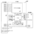
次に、パチンコ遊技機1の遊技制御に用いられる制御回路について説明する。図2および図3は、パチンコ遊技機1の遊技制御に用いられる各種制御回路の構成を示すブロック図である。それらの各種制御回路は、パチンコ遊技機1の裏面側に取付けられた遊技制御基板に設けられている。
Next, a control circuit used for game control of the
図2および図3を参照して、制御回路は、基本回路45、アドレスデコード回路41、入力回路35、LED回路46、情報出力回路37、初期リセット回路38、定期リセット回路39、電飾信号回路40、ソレノイド回路48、CRT回路54、ランプ回路55、音声合成回路56、音量増幅回路57、および、電源回路58を含む。
2 and 3, the control circuit includes a basic circuit 45, an
基本回路45は、遊技制御用プログラムに従ってパチンコ遊技機1の各種機器を制御する。基本回路45は、マイクロコンピュータ(マイコン)68により構成されている。マイクロコンピュータ68には、遊技制御用プログラムを記憶しているROM(Read Only Memory)69、遊技制御用プログラムに従って制御動作を行なうためのCPU(Central Processing Unit )71、CPUのワーク用メモリとして機能するRAM(Random Access Memory)70、図示を省略したI/O(Input/Output)ポート、および、図示を省略したクロック発生回路などが含まれている。
The basic circuit 45 controls various devices of the
入力回路35は、始動口9に始動入賞した打玉を検出するための始動玉検出器34と、可変入賞球装置12の特定入賞領域に入賞した打玉を検出するための特定球検出スイッチ32と、可変入賞球装置12の大入賞口に入賞した打玉を検出するための球数検出スイッチ33と、普通図柄始動ゲート8を通過した打玉を検出するための通過球検出器13とそれぞれ接続される。入力回路35は、特定球検出スイッチ32、球数検出スイッチ33および通過球検出器13の各検出器から出力される検出信号を基本回路45へ送信する。
The
LED回路46は、個数表示器25のLED、始動記憶表示器6のLED、普通図柄表示器20の普通図柄を表示するためのLED、通過記憶表示器21のLED、および、LED24を含むその他のLED47と接続される。LED回路46は、基本回路45から出力される制御信号に応じて、上記各LEDの点灯状態を制御する。
The
初期リセット回路38は、電源投入時に基本回路45をリセットするための回路である。初期リセット回路38から送られてきた初期リセットパルスに応答して、基本回路45はパチンコ遊技機1を初期化する。
The initial reset circuit 38 is a circuit for resetting the basic circuit 45 when the power is turned on. In response to the initial reset pulse sent from the initial reset circuit 38, the basic circuit 45 initializes the
定期リセット回路39は、基本回路45に対し、定期的(たとえば2msecごと)にリセットパルスを与え、基本回路45のROMに記憶されている遊技制御用プログラムを先頭から繰返し実行させるための回路である。 The periodic reset circuit 39 is a circuit for giving a reset pulse to the basic circuit 45 periodically (for example, every 2 msec) and repeatedly executing the game control program stored in the ROM of the basic circuit 45 from the top. .
この種のパチンコ遊技機1では、大当たりを発生させるか否かの判定が基本回路45のRAM70内に構成された大当たり決定用カウンタのカウンタ値を大当たり決定値と比較照合することにより行なわれる。基本回路45は、入力回路35から始動入賞信号が入力されてきたタイミングで大当たり決定用カウンタのカウンタ値を抽出してそのカウンタ値が予め定められている大当たり決定値であるか否かを判定し、大当たり決定値である場合には、大当たりを発生させることを事前決定する。
In this type of
ソレノイド回路48は、始動口9の可動片14を駆動するためのソレノイド50、および可変入賞球装置12の開閉板22を駆動するためのソレノイド49を制御するための回路である。ソレノイド回路48は、基本回路45から出力される制御信号に応答して、所定のタイミングでソレノイド50およびソレノイド49を作動させる。
The solenoid circuit 48 is a circuit for controlling a
アドレスデコード回路41は、基本回路45から送られてきたアドレス信号をデコードし、基本回路45に含まれるROM69およびRAM70などのいずれか1つを選択するための信号を出力する回路である。
The
情報出力回路37は、基本回路45から与えられるデータ信号に基づいて、大当たり情報や図柄確定情報、確率変動情報などの各種遊技情報をホストコンピュータであるホール用管理コンピュータなどに対して出力する。ここで、大当たり情報とは、大当たりの発生を示すための情報であり、図柄確定情報とは、始動口9に入賞した打玉の入賞個数のうち実際に可変表示装置4における図柄の可変表示の始動に使用された個数を示すための情報であり、確率変動情報とは、確率変動状態の発生に関する情報である。
Based on the data signal given from the basic circuit 45, the
電飾信号回路40は、パチンコ遊技機1に設けられた複数種類の電飾(図示省略)の点灯状態を制御する電飾基板(図示省略)へランプ制御データD0〜D3を送信する。ランプ制御データD0〜D3は、電飾の点灯状態を制御するためのデータであり、大当たり時、あるいは高確率状態などにおける電飾の点灯状態を指定する。なお、ランプ制御データコモンは共通線信号である。
The electrical
CRT回路54は、基本回路45から出力される表示制御データに従って、CRT表示機53を駆動制御するための回路である。CRT回路54からCRT表示機53に送信される表示制御データの中には、コマンド信号としてのCD0〜CD7と、表示制御通信トリガ信号(割込信号)であるINTとが含まれる。さらに、CRT回路54とCRT表示機53とを接続する信号線には、電源供給のための+5V線と、+12V線と、グランド信号線であるGND線とがある。基本回路45は、定期リセット回路39からの定期リセット信号が入力されたタイミングでCRT回路54を介して画像表示制御基板(サブ基板)216へ、割込信号(INT)と画像表示制御信号(コマンド信号CD0〜CD7)とを出力する。
The
ランプ回路55は、サイドランプ22等の各種ランプと接続される。ランプ回路55は、基本回路45から出力される制御信号に応じて、上記各種ランプの点灯状態を制御する。
The
電源回路58は、AC24Vの交流電源に接続され、+30V、+21V、+12V、+5Vの複数種類の直流電圧を各回路に供給するための回路である。なお、電源回路58から発生される+30Vの直流電圧はCRT表示機53へ出力される。
The
音声合成回路56は、基本回路45から出力される音声発生指令信号に応じて効果音データを合成し、合成した効果音データを音量増幅回路57に与える。音量増幅回路57は、効果音を増幅して電飾基板へ出力する。
The
図4は、画像表示制御基板(サブ基板)216に形成された回路の構成を示すブロック図である。画像表示制御基板216は、遊技制御基板(コントロール基板)112からの制御信号に応じて可変表示装置4の表示状態を制御する。
FIG. 4 is a block diagram showing a configuration of a circuit formed on the image display control board (sub board) 216. The image
画像表示制御基板216には、CRTコントロール回路67、VDP(Video Display Processor)59、リセット回路64、発振回路65、VRAM60、キャラクタROM61、DA変換回路62が設けられている。
The image
CRTコントロール回路67は、図2、図3に示した回路が形成されている遊技制御基板112と接続されている。CRTコントロール回路67は、遊技制御基板112から画像表示のためのコマンドデータCD0〜CD7、INT信号を定期的に受ける。さらに、CRTコントロール回路67は、+12Vおよび+5Vの2種類の電源電圧の供給を受ける。また、画像表示制御基板216は、遊技制御基板112から延びるGND線により接地されている。
The
CRTコントロール回路67は、受信したコマンドデータCD0〜CD7に応答して、画像表示制御基板216に形成された回路全体を制御する。CRTコントロール回路67は、VDP59にアドレス信号、データ信号および制御信号を送り、VDP59とCRTコントロール回路67との間で、データ信号の送受信を行なう。そして、CRTコントロール回路67は、受信したデータに基づいて、画像表示制御基板216に形成された回路全体の制御を行なう。
The
VDP59は、発振回路65から供給されるクロック信号を受けて動作し、リセット回路64から供給されるリセット信号を受けて動作がリセットされる。このVDP59は、CRTコントロール回路67からの制御信号に応答して、画像データを生成する。VDP59は、VRAMアドレス信号、VRAMデータ信号、およびVRAM制御信号などの信号をVRAM60へ送信する。VRAM60からVDP59へは、VRAMデータ信号などの信号が返信される。VDP59は、キャラクタROMアドレス信号、キャラクタROMデータ信号およびキャラクタROM制御信号をキャラクタROM61へ送信する。キャラクタROM61からVDP59へは、キャラクタROMデータ信号などの信号が返信される。
The
VDP59は、CRTコントロール回路67から出力される制御信号に応答して、画像表示部5に表示される画像を構成するための画像データを生成する。VRAM60は、VDP59が生成した画像データを一時的に記憶する。VDP59が生成し、VRAM60に記憶される画像データは、所定数のドットの集合を単位としたキャラクタの識別番号である。ここで、キャラクタとは、可変表示装置4に表示される人間,動物,あるいは物等を表わす映像をいう。
In response to the control signal output from the
画像データには、複数のキャラクタの識別番号が、表示される配置関係に従って含まれている。これをマップデータという。個々のキャラクタの識別番号は、CRTコントロール回路67内に予め記憶されている。画像表示部5に表示される画面を構成するために必要なキャラクタの識別番号がCRTコントロール回路67から読出され、VDP59により、表示画面におけるキャラクタの配置関係を示すためのマップデータとして、VRAM60に記憶される。
The image data includes the identification numbers of a plurality of characters according to the displayed arrangement relationship. This is called map data. The identification number of each character is stored in advance in the
キャラクタROM61は、キャラクタの識別番号に対応するドットデータを予め記憶している。VDP59は、所定のタイミングでVRAM60からマップデータを読出し、マップデータに含まれる各キャラクタの識別番号に基づいて、各キャラクタのドットデータを読出す。VDP59は、読出したドットデータに基づいて、画像表示信号を生成する。生成された信号は、DA変換回路62によりアナログのRGB(RED,GREEN,BLUE)信号に変換されて画像表示用の表示装置63に入力される。さらにVDP59は、複合同期信号SYNCを表示装置63へ供給する。表示装置63は、送信されてきたRGB信号、複合同期信号SYNCに基づいて、画像表示部5に画像を表示する。なお、表示装置63は、遊技制御基板112から延びるGND線により接地されている。
The character ROM 61 stores dot data corresponding to the character identification number in advance. The
図5は、パチンコ遊技機1に用いられる主なランダムカウンタやバンク、フラグを説明するための説明図である。以下に図5を参照して、各種ランダムカウンタやバンク、フラグの内容について説明する。なお、図5に示したラベル名により識別される各種ランダムカウンタ等のデータはCPU71のワーク用メモリとして機能するRAM70内に記憶されている。
FIG. 5 is an explanatory diagram for explaining main random counters, banks, and flags used in the
BANK0〜BANK3は、始動入賞に関連する各種情報を始動入賞別に記憶するためのバンクである。BANK0〜BANK3により、始動入賞を最大4つ記憶することが可能になる。各バンクBANK0〜BANK3には、始動入賞毎に、C_HITおよびC_KHITなどの抽出値を記憶するための複数の記憶領域に分割されている。 BANK0 to BANK3 are banks for storing various types of information related to start-up winnings according to start-up winnings. With BANK0 to BANK3, it is possible to store up to four start winnings. Each bank BANK0 to BANK3 is divided into a plurality of storage areas for storing extracted values such as C_HIT and C_KHIT for each start winning prize.
始動入賞が発生した時点で始動記憶が無い場合には、BANK0にC_HITおよびC_KHIT等の各種情報が記憶される。一方、始動入賞が発生した時点で始動記憶が存在する場合には、記憶のなされていないバンクのうち、最も若いバンク番号のバンクに始動入賞関連の各種情報が記憶される。なお、4つのバンクすべてに記憶がなされている場合には、新たな始動入賞に関連する各種情報は記憶されることはない。このため、その始動入賞は無効になる。 If there is no start memory when the start winning is generated, various information such as C_HIT and C_KHIT is stored in BANK0. On the other hand, when the start memory exists at the time when the start winning is generated, various information related to the start winning is stored in the bank having the youngest bank number among the banks that are not stored. If all four banks are stored, various information related to the new start winning prize is not stored. For this reason, the start winning is invalid.
ERR_Fは、エラーフラグである。遊技制御の途中に所定のエラーが発生すれば、このエラーフラグが所定値に設定される。たとえば、カウントスイッチ短絡エラーが発生した場合にはエラーフラグが「01H」に設定され、特定領域スイッチ短絡エラーが発生した場合にはエラーフラグが「02H」に設定され、大入賞口未入賞エラーが発生した場合はエラーフラグが「04H」に設定され、特定領域通過エラーが発生した場合にはエラーフラグが「08H」に設定され、不正入賞エラーが発生した場合にはエラーフラグが「10H」に設定される。エラーフラグが所定値に設定されることにより、可変表示装置4の上部に設けられたエラーコード表示部200(図1参照)には、各エラーフラグ値に対応したエラーコードが表示される。
ERR_F is an error flag. If a predetermined error occurs during game control, this error flag is set to a predetermined value. For example, when a count switch short-circuit error occurs, the error flag is set to “01H”, and when a specific area switch short-circuit error occurs, the error flag is set to “02H”. If it occurs, the error flag is set to “04H”, if a specific area passing error occurs, the error flag is set to “08H”, and if an illegal winning error occurs, the error flag is set to “10H”. Is set. By setting the error flag to a predetermined value, an error code corresponding to each error flag value is displayed on the error code display unit 200 (see FIG. 1) provided at the top of the
なお、カウントスイッチ短絡エラーは球数検出スイッチ33が断線等した場合に発生するエラーであり、特定領域スイッチ短絡エラーは特定球検出スイッチ32が断線等した場合に発生するエラーであり、大入賞口未入賞エラーは可変入賞球装置12が開放状態となってから30秒が経過しているにもかかわらず入賞球が検出されない場合に発生するエラーであり、特定領域通過エラーは特定球検出スイッチ32によりV入賞が検出されたにもかかわらず球数検出スイッチ33の検出出力が得られない場合に発生するエラーであり、不正入賞エラーは大当り中でないのに球数検出スイッチ33から検出信号が入力された場合に発生するエラーである。
The count switch short circuit error is an error that occurs when the ball
PRO_Fは、特別図柄プロセスフラグである。この特別図柄プロセスフラグのフラグ状態により、複数種類のサブルーチンプログラムからなる遊技制御プログラムのうち、いずれのサブルーチンプログラムを実行すべきであるかが指定される。特別図柄プロセスフラグが「00H」に設定されている場合には、特別図柄変動待ち処理が指定される。特別図柄プロセスフラグが「01H」の場合には、大当り判定処理が指定される。特別図柄プロセスフラグが「02H」の場合には、停止図柄設定処理が指定される。特別図柄プロセスフラグが「03H」に設定されている場合には、装飾キャラクタ等設定処理が指定される。プロセスフラグが「04H」の場合には、全図柄変動開始処理が指定される。プロセスフラグが「05H」の場合には、各図柄停止処理が指定される。特別図柄プロセスフラグが「06H」の場合には、大当り中処理が指定される。 PRO_F is a special symbol process flag. According to the flag state of the special symbol process flag, it is specified which subroutine program should be executed among the game control programs including a plurality of types of subroutine programs. When the special symbol process flag is set to “00H”, special symbol variation waiting processing is designated. When the special symbol process flag is “01H”, the big hit determination process is designated. When the special symbol process flag is “02H”, stop symbol setting processing is designated. When the special symbol process flag is set to “03H”, a decoration character setting process is designated. When the process flag is “04H”, all symbol variation start processing is designated. When the process flag is “05H”, each symbol stop process is designated. When the special symbol process flag is “06H”, the big hit processing is designated.
次にランダムカウンタについて説明する。ランダムカウンタとは、大当りの決定および可変表示装置4の特別図柄の可変表示制御などの各種制御に用いられる乱数をカウントするカウンタである。ここでは、ランダムカウンタの代表例として、C_HIT、C_KHIT、C_HEN、C_YOKの4種類のランダムカウンタが示されている。これらのランダムカウンタの値がパチンコ遊技中の所定のタイミングで抽出され、その値に基づいて各種制御が行なわれる。ランダムカウンタのカウント値の抽出処理は、基本回路45の内部に設けられたCPU71がROM69に格納された遊技制御用プログラムに従って実行する。
Next, the random counter will be described. The random counter is a counter that counts random numbers used for various controls such as determination of jackpot and variable display control of special symbols of the
C_HITは、可変表示装置4における特別図柄の可変表示の結果、大当りを発生させるか否かを決定するための大当り決定用のランダムカウンタである。C_HITは、0〜599のカウント範囲において、カウンタ値が所定タイミングごとに1つずつカウントアップ(加算)される。C_HITは、その上限までカウントアップされると、再度0からカウントし直すように構成されている。
C_HIT is a jackpot determining random counter for determining whether or not to generate a jackpot as a result of variable display of a special symbol on the
C_HITの抽出値が予め定められた大当り判定値と一致した場合には、大当りを発生させることが事前に決定される。大当り判定値は、確率変動時と、それ以外の通常時とで異なっている。通常時における大当り判定値(低確率時判定値)は、7〜9に設定されている。一方、確率変動時における大当り判定値(高確率時判定値)は、7〜16に設定されている。 When the extracted value of C_HIT matches a predetermined jackpot determination value, it is determined in advance that a jackpot will be generated. The jackpot determination value is different between the probability variation time and the other normal time. The big hit determination value (low-probability determination value) at the normal time is set to 7-9. On the other hand, the jackpot determination value at the time of probability change (high probability determination value) is set to 7-16.
C_KHITは、可変表示装置4の表示結果として導出される左図柄(第1停止図柄)、右図柄(第2停止図柄)、中図柄(第3停止図柄)のうち、左図柄(第1停止図柄)の種類を決定するための図柄決定用のランダムカウンタである。C_KHITは、0〜9のカウント範囲において、カウンタ値が所定タイミングごとに1ずつカウントアップ(加算)される。C_KHITは、その上限までカウントアップされると、再度0からカウントをし直すように構成されている。 C_KHIT is the left symbol (first stop symbol) among the left symbol (first stop symbol), right symbol (second stop symbol), and middle symbol (third stop symbol) derived as the display result of the variable display device 4. ) Is a random counter for determining symbols. C_KHIT is incremented (added) by 1 at a predetermined timing in the count range of 0 to 9. C_KHIT is configured to start counting from 0 again when it is counted up to the upper limit.
C_KHITの抽出値が、「1」,「3」,「5」,「7」,「9」のうちのいずれかである場合には、第1停止図柄が確変図柄に設定される。一方、C_KHITの抽出値が、「0」,「2」,「4」,「6」,「8」のうちのいずれかである場合には、第1停止図柄が確変図柄以外の大当り図柄に設定される。先に説明したC_HITの抽出値に基づいて大当りとすることが決定された場合には、右図柄(第2停止図柄)および中図柄(第3停止図柄)がC_KHITの抽出値に基づいて定められた図柄と同一種類の図柄に設定される。一方、C_HITの抽出値に基づいてハズレとすることが決定された場合には、右図柄(第2停止図柄)および中図柄(第3停止図柄)のうち少なくとも一方がC_KHITの抽出値に基づいて定められた図柄と異なる種類の図柄に設定される。 When the extracted value of C_KHIT is any one of “1”, “3”, “5”, “7”, “9”, the first stop symbol is set as the probability variable symbol. On the other hand, when the extracted value of C_KHIT is any one of “0”, “2”, “4”, “6”, “8”, the first stop symbol becomes a jackpot symbol other than the probability variation symbol. Is set. When it is determined that the big hit is based on the C_HIT extraction value described above, the right symbol (second stop symbol) and the middle symbol (third stop symbol) are determined based on the C_KHIT extraction value. The same type of symbol as the selected symbol is set. On the other hand, when it is determined to lose based on the extracted value of C_HIT, at least one of the right symbol (second stop symbol) and the middle symbol (third stop symbol) is based on the extracted value of C_KHIT. It is set to a different kind of symbol from the defined symbol.
C_HENは、特別図柄の可変開始から可変停止までの図柄停止パターンを決定するためのランダムカウンタである。C_HENは、0〜255のカウント範囲において、カウンタ値が所定タイミングごとに1ずつカウントアップ(加算)される。C_HENは、その上限までカウントアップされると、再度0からカウントし直すように構成されている。 C_HEN is a random counter for determining a symbol stop pattern from variable start to variable stop of a special symbol. C_HEN is incremented (added) by 1 at a predetermined timing in the count range of 0 to 255. When C_HEN is counted up to the upper limit, C_HEN is configured to start counting from 0 again.
基本回路45のROM69には、C_HENの抽出値に基づいて図柄停止パターンを決定するために参照される図柄停止パターン決定用テーブルが3種類記憶されている。1つ目は、可変表示結果を大当りとすることが決定された場合に参照される大当り時図柄停止パターン決定用テーブルである。2つ目は、ハズレリーチとすることが決定された場合に参照されるハズレリーチ時図柄停止パターン決定用テーブルである。なお、ハズレリーチとは、可変表示の途中にリーチ表示状態が表示された後、可変表示結果がハズレとなるものである。3つ目は、可変表示結果をハズレとし、かつ、リーチを成立させないことが決定された場合に参照されるハズレ時図柄停止パターン決定用テーブルである。
The
基本回路45のCPU71は可変表示結果を事前に決定した後、その決定結果を記憶しておき、図柄停止パターンを決定する際に先に記憶した決定結果を参照する。そして、可変表示結果を大当りとすることが決定されている場合には停止パターン決定用判定値3を設定し、ハズレリーチとすることが決定されている場合には停止パターン決定用判定値2を設定し、可変表示結果をハズレ(リーチなし)とすることが決定されている場合には停止パターン決定用判定値1を設定する。その後、停止パターン決定用判定値1が設定されている場合にはハズレ時図柄停止パターン決定用テーブルを、停止パターン決定用判定値2が設定されている場合にはハズレリーチ時停止パターン決定用テーブルを、停止パターン決定用判定値3が設定されている場合には大当り時停止パターン決定用テーブルを、それぞれ参照する。各停止パターン決定用テーブルにはC_HENのカウント値(0〜255)が各種図柄停止パターンのうちの何れかに対応づけられている。基本回路45のCPU71は、所定のタイミングで抽出され記憶されているC_HENの抽出値をRAM70から読出し、読出した抽出値が停止パターン決定用テーブル内で対応づけられている図柄停止パターンを検索する。そして、検索結果に基づいて図柄停止パターンを決定する。
After determining the variable display result in advance, the
C_YOKは、大当り予告をするか否かを決定するとともに大当り予告のための予告動作の種類を決定するためのランダムカウンタである。このパチンコ遊技機1では、CPU71によって選択される予告動作の種類として「特別図柄変動1」と「特別図柄変動2」とがある。C_YOKは、0〜49のカウント範囲において、カウンタ値が所定タイミングごとに1ずつカウントアップ(加算)される。C_YOKは、その上限までカウントアップされると、再度0からカウントをし直すように構成されている。
C_YOK is a random counter for deciding whether or not to make a jackpot notice and determining the type of notice action for the jackpot notice. In this
基本回路45のROM69には、C_YOKの抽出値に基づいて大当り予告をするか否かを決定するとともに大当り予告のための予告動作の内容を決定する際に参照される予告動作決定用テーブルが2種類記憶されている。1つは、可変表示結果を大当りとすることが決定された場合に参照される大当り時予告動作決定用テーブルである。もう1つは、可変表示結果をハズレとすることが決定された場合に参照されるハズレ時予告動作決定用テーブルである。
The
基本回路45のCPU71は可変表示結果を事前に決定した後、その決定結果を記憶しておき、予告動作に関する決定する際に先に記憶した決定結果を参照する。そして、可変表示結果を大当りとすることが決定されている場合には予告動作判定値2を設定し、ハズレとすることが決定されている場合には予告動作判定値1を設定する。その後、予告動作判定値1が設定されている場合にはハズレ時予告動作決定用テーブルを、予告動作判定値2が設定されている場合には大当り時予告動作決定用テーブルを、それぞれ参照する。各予告動作決定用テーブルにはC_YOKのカウント値(0〜49)が「特別図柄変動1」、「特別図柄変動2」、または「予告動作なし」のうちの何れかに対応づけられている。基本回路45のCPU71は、所定のタイミングで抽出され記憶されているC_YOKの抽出値をRAM70から読出し、読出した抽出値が予告動作決定用テーブル内で対応づけられているデータを検索する。そして、検索結果に基づいて予告動作に関する決定をする。
After determining the variable display result in advance, the
特にこの実施形態では、「特別図柄変動1」の予告動作が実行された場合よりも「特別図柄変動2」の予告動作が実行された場合の方が、その予告動作後に導出される可変表示結果が大当りとなる可能性が高くなるように、ハズレ時予告動作決定用テーブルおよび大当り時予告動作決定用テーブルにおいてC_YOKのカウント値(0〜49)が「特別図柄変動1」および「特別図柄変動2」に対応づけられている。このため、「特別図柄変動1」の予告動作が実行された場合よりも「特別図柄変動2」の予告動作が実行された場合の方が、大当り予告の的中率が高くなる。
In particular, in this embodiment, the variable display result derived after the notice operation is performed when the notice operation of “
図6は、C_HENの抽出値に基づいて各種図柄停止パターンが選択される割合を停止パターン決定用判定値別に示す図である。この実施形態では、図柄停止パターンとして、次の7パターンがある。 FIG. 6 is a diagram showing the ratios at which various symbol stop patterns are selected based on the extracted value of C_HEN for each stop pattern determination value. In this embodiment, there are the following seven patterns as symbol stop patterns.
(1)通常パターン(2)通常パターンに続いて停止パターンAを実行するパターン(通常パターン+停止パターンAと記載する。以下、同様。)(3)通常パターン+停止パターンA+停止パターンB(4)通常パターン+停止パターンA+停止パターンB+停止パターンC(5)通常パターン+停止パターンD(6)通常パターン+停止パターンD+停止パターンE(7)通常パターン+停止パターンD+停止パターンE+停止パターンF
図6において、たとえば、「停止パターンA」とは、前記(2)の「通常パターン+停止パターンA」を意味している。同様に、「停止パターンF」とは、前記(7)の「通常パターン+停止パターンD+停止パターンE+停止パターンF」を意味している。複数種類のパターンが組合せられた図柄停止パターン程、可変表示開始から最終的な表示結果が確定するまでの可変表示時間が長くなる。
(1) Normal pattern (2) Pattern that executes stop pattern A following the normal pattern (referred to as normal pattern + stop pattern A. The same applies hereinafter) (3) Normal pattern + stop pattern A + stop pattern B (4 ) Normal pattern + Stop pattern A + Stop pattern B + Stop pattern C (5) Normal pattern + Stop pattern D (6) Normal pattern + Stop pattern D + Stop pattern E (7) Normal pattern + Stop pattern D + Stop pattern E + Stop pattern F
In FIG. 6, for example, “stop pattern A” means “normal pattern + stop pattern A” of (2). Similarly, “stop pattern F” means “normal pattern + stop pattern D + stop pattern E + stop pattern F” of (7). As the symbol stop pattern in which a plurality of types of patterns are combined, the variable display time from the start of variable display until the final display result is determined becomes longer.
この図6においては、各種図柄停止パターンが選択される割合の高いものから順に◎、○、△、×の記号で示している。たとえば、可変表示結果をハズレとすることが決定されている場合に参照される停止パターン決定用判定値1が設定されている場合には、前記(1)の通常パターン1が選択される割合が最も高く、選択される割合が前記(2)、(3)、(4)、または前記(5)、(6)、(7)の順に低くなる。一方、可変表示結果を大当りとすることが決定されている場合に参照される停止パターン決定用判定値3が設定されている場合には、前記(1)の通常パターン1が選択される割合が最も低く、選択される割合が前記(2)、(3)、(4)、または前記(5)、(6)、(7)の順に高くなる。さらに、可変表示結果をハズレリーチとすることが決定されている場合に参照される停止パターン決定用判定値2が設定されている場合には、前記(2)の「通常パターン+停止パターンA」または前記(5)の「通常パターン+停止パターンD」が選択される割合が最も高く、選択される割合が前記(2)、(3)、(4)、または前記(5)、(6)、(7)の順に低くなる。また、前記(1)が選択される割合は、前記(3)または前記(6)が選択される割合と同一である。
In FIG. 6, symbols ◎, ◯, Δ, and X are shown in order from the one with the highest proportion of various symbol stop patterns to be selected. For example, when the stop pattern
以上より、図柄停止パターンが通常パターンから停止パターンA、停止パターンAから停止パターンB、停止パターンBから停止パターンCへと次々に変化していくような可変表示制御が行なわれる程、遊技者の立場からすると、最終的な可変表示結果が大当りとなることを期待できる率(期待値という)が大きくなることになる。一方、停止パターンの変化が乏しい程、期待値が小さくなる。 From the above, as the variable display control is performed so that the symbol stop pattern changes from the normal pattern to the stop pattern A, from the stop pattern A to the stop pattern B, and from the stop pattern B to the stop pattern C, the player's From the standpoint, the rate at which the final variable display result can be expected to be a big hit (referred to as an expected value) will increase. On the other hand, the less the stop pattern changes, the smaller the expected value.
図7は、大当り予告の制御動作を示すタイミングチャートである。同図を参照しつつ、大当り予告の制御動作について説明する。この実施形態では、予告動作の種類として、「特別図柄変動1」と「特別図柄変動2」とがある。前述のように、「特別図柄変動2」の方が「特別図柄変動1」よりも大当り予告の的中率が高い。
FIG. 7 is a timing chart showing the control operation for jackpot notice. The control operation for the jackpot notice will be described with reference to FIG. In this embodiment, there are “
最初に、「特別図柄変動1」について説明する。まず、始動入賞の検出に基づいて、パターンAによる制御が実行される。パターンAによる制御が実行されることにより、左、中、右の各可変表示部に停止表示されている第1停止図柄〜第3停止図柄がスクロール方向に振動を開始し、時間の経過とともにその揺れ幅が大きくなる。また、特別図柄の振動に合わせてスピーカ81からは所定の効果音が発生し、揺れ幅が大きくなるにつれて効果音の音量が次第に大きくなる。その後、揺れ幅が所定の大きさになった段階で表示パターンAによる表示制御が終了してスクロール表示となり、特別図柄の変動が開始される。
First, “
次に、「特別図柄変動2」について説明する。「特別図柄変動2」の場合においても、「特別図柄変動1」の場合と同様にしてパターンAによる制御が実行される。ただし、パターンAによる制御が実行されている期間が「特別図柄変動1」の場合よりも長い。このため、「特別図柄変動1」の場合よりも大きな揺れ幅で特別図柄が揺れるようになり、かつ、「特別図柄変動1」の場合よりも大きな効果音が発せられるようになる。その後、振幅が所定の大きさになった段階で表示パターンAによる制御が終了して表示パターンBによる制御が実行される。パターンBによる制御が実行されることにより、特別図柄の揺れと効果音の音量とがともに最大となる。その後、表示パターンBによる表示制御が終了してスクロール表示となり、特別図柄の変動が開始される。
Next, “
なお、図示を省略するが、前述した「予告動作なし」とすることが決定され、大当り予告動作が行なわれない場合には、始動入賞の検出に基づいた可変表示制御が実行可能となれば、即座にスクロール表示となり、特別図柄の変動が開始される。 Although illustration is omitted, if it is determined that the above-mentioned “no notice operation” is performed and the big hit notice operation is not performed, if variable display control based on the detection of the start winning can be performed, Immediately scroll display is displayed, and the special symbol changes.
以上、説明した制御動作によって大当り予告がなされることにより、大当りに対する遊技者の期待感を向上させることができる。また、揺れ幅が除々に大きくなるとともに効果音も除々に大きくなることにより、周囲の遊技客の注目を浴びるようになり、遊技者本人は優越感に浸れるようになる。特に、「特別図柄変動1」よりも大当り予告の的中率の高い「特別図柄変動2」の場合には、特別図柄の揺れ幅と効果音の音量とが最大になって予告動作が派手に行なわれるために遊技者および周囲の遊技客に対するアピール度合いが大きくなり、遊技者の期待感と優越感とを最大限に高めることができる。
As described above, when the jackpot notice is made by the control operation described above, it is possible to improve the player's expectation for the jackpot. In addition, since the amplitude of the vibration gradually increases and the sound effect gradually increases, the player is attracted to the surrounding players, and the player himself / herself is immersed in a sense of superiority. In particular, in the case of “
次に、基本回路45が実行する遊技制御の内容を説明する。図8は、遊技制御のメインプログラムの処理手順を示すフローチャートである。まず、ステップS(以下、単にSという)1によりクロックモニタ制御レジスタをクロックモニタイネーブルに設定する処理がなされる。次に、S2により、スタックポインタのアドレス(00FFH)を設定する処理がなされる。 Next, the contents of the game control executed by the basic circuit 45 will be described. FIG. 8 is a flowchart showing the processing procedure of the main program for game control. First, in step S (hereinafter simply referred to as S) 1, processing for setting the clock monitor control register to clock monitor enable is performed. Next, the process of setting the stack pointer address (00FFH) is performed in S2.
次に、S3により、システムチェック処理が実行される。このシステムチェック処理においては、遊技制御の実行に用いられる基本回路45のRAM70の作業領域の初期化が行なわれる。次に、S4により、表示制御データ設定処理が実行される。この表示制御データ設定処理においては、表示制御データを書込むRAM70のアドレスが設定される。次に、S5により、表示制御データ伝送処理が実行される。この表示制御データ伝送処理においては、表示制御データを画像表示制御基板216のCRTコントロール回路67に向けて伝送する処理が行なわれる。
Next, system check processing is executed in S3. In this system check process, the work area of the
次に、S6により、データ出力処理が実行される。このデータ出力処理においては、各種機器の制御を行なうための制御データおよびパチンコ遊技機1の外部に所定の情報を出力するための情報データを出力する処理が行なわれる。次に、S7により、ランプタイマ処理が実行される。このランプタイマ処理においては、タイマを用いて各種ランプを動作させるための処理が行なわれる。
Next, a data output process is executed in S6. In this data output process, a process of outputting control data for controlling various devices and information data for outputting predetermined information to the outside of the
次に、S8により、出力データ設定処理が実行される。このデータ設定処理においては、S6により出力するデータを設定するための処理が行なわれる。次に、S9により、エラー処理が実行される。このエラー処理においては、エラー状態が発生した場合にエラー状態を設定してその旨の報知を行なう処理と、所定条件下でエラー状態を解除する処理とが行なわれる。次に、S10により、判定用乱数更新処理が実行される。この判定用乱数更新処理においては、前述した大当り決定用のランダムカウンタC_HIT等を更新する処理が行なわれる。 Next, an output data setting process is executed in S8. In this data setting process, a process for setting data to be output is performed in S6. Next, error processing is executed in S9. In this error processing, when an error condition occurs, a process for setting the error condition and notifying that effect and a process for canceling the error condition under a predetermined condition are performed. Next, the determination random number update process is executed in S10. In this determination random number update process, the above-described process for updating the jackpot determining random counter C_HIT and the like is performed.
次に、S11により、特別図柄プロセス処理が実行される。この特別図柄プロセス処理においては、複数のプロセスに分けられた特別図柄を表示するためのプロセスを、プロセスを選択するフラグに応じて分岐実行させるための処理が行なわれる。次に、S12により、普通図柄プロセス処理が実行される。この普通図柄プロセス処理においては、複数のプロセスに分けられた普通図柄を表示するためのプロセスを、プロセスを選択するフラグに応じて分岐実行させるための処理が行なわれる。 Next, a special symbol process process is performed by S11. In this special symbol process, a process for displaying a special symbol divided into a plurality of processes is executed according to a flag for selecting a process. Next, the normal symbol process is executed in S12. In this normal symbol process process, a process for displaying a normal symbol divided into a plurality of processes is executed according to a flag for selecting a process.
次に、S13により、スイッチ処理が実行される。このスイッチ処理においては、特定球検出スイッチ32および球数検出スイッチ33等の各種スイッチのスイッチ別の出力信号の論理判定を実行させるための処理が行なわれる。次に、S14により、音声処理が実行される。この音声処理においては、効果音等に用いられる音声を出力するための処理が行なわれる。
Next, a switch process is performed by S13. In this switch process, a process for executing a logical determination of the output signal for each switch of various switches such as the specific
次に、S15により、表示用乱数更新処理が実行される。この表示用乱数更新処理においては、C_YOK等の可変表示のために用いる各種ランダムカウンタを更新する処理がなされる。次に、S16により、入賞球信号処理がなされる。この入賞球信号処理においては、入賞球の検出に応じた景品玉の払出しを実行させるための処理が行なわれる。次に、S17により、S14と同様の表示用乱数更新処理が繰返し実行される。 Next, a display random number update process is executed in S15. In this display random number updating process, various random counters used for variable display such as C_YOK are updated. Next, in S16, winning ball signal processing is performed. In the winning ball signal processing, processing for executing payout of prize balls according to detection of winning balls is performed. Next, the display random number update process similar to S14 is repeatedly executed through S17.
次に、前述したS11の特別図柄プロセス処理の内容を詳細に説明する。図9は、特別図柄プロセス処理の処理内容を示すフローチャートである。 Next, the contents of the special symbol process in S11 will be described in detail. FIG. 9 is a flowchart showing the contents of the special symbol process.
まず、図示を省略しているが、遊技の状態を示すプロセスフラグがどのような値にセットされているかの判別が行なわれる。このプロセスフラグは、所定の制御時間を保ちながらパチンコ遊技機を順序正しく制御するために必要となるものであり、遊技状態の進行状況に応じてその値が更新される。このようなプロセスフラグの値に応じて図9に示されるように、実行されるプログラムが選択される。 First, although not shown, it is determined what value the process flag indicating the game state is set to. This process flag is necessary for controlling pachinko gaming machines in order while maintaining a predetermined control time, and the value thereof is updated according to the progress of the gaming state. As shown in FIG. 9, a program to be executed is selected according to the value of the process flag.
プロセスフラグが「0」の場合には、S18による特別図柄変動待ち処理が行なわれる。特別図柄変動待ち処理の内容については、図10を用いて後述する。プロセスフラグが「1」の場合には、S19による大当り判定処理が行なわれる。大当り判定処理の内容については、図11を用いて後述する。プロセスフラグが「2」の場合には、S20による停止図柄設定処理が行なわれる。停止図柄設定処理の内容については、図12を用いて後述する。プロセスフラグが「3」の場合には、S21による装飾キャラクタ等設定処理が行なわれる。装飾キャラクタ等設定処理の内容については、図13を用いて後述する。プロセスフラグが「4」の場合には、S22による全図柄変動開始処理が行なわれる。全図柄変動開始処理の内容については、図14を用いて後述する。プロセスフラグが「5」の場合には、S23による各図柄停止処理が行なわれる。各図柄停止処理の内容については、図15を用いて後述する。プロセスフラグが「6」の場合には、S24による大当り中処理が行なわれる。大当り中処理の実行により、前述したような大当り状態での各種の制御動作が行なわれる。 When the process flag is “0”, a special symbol variation waiting process in S18 is performed. The contents of the special symbol variation waiting process will be described later with reference to FIG. When the process flag is “1”, the big hit determination process in S19 is performed. The contents of the big hit determination process will be described later with reference to FIG. When the process flag is “2”, the stop symbol setting process in S20 is performed. The contents of the stop symbol setting process will be described later with reference to FIG. When the process flag is “3”, a decoration character setting process in S21 is performed. The contents of the decoration character setting process will be described later with reference to FIG. When the process flag is “4”, all symbol variation start processing in S22 is performed. The contents of all symbol variation start processing will be described later with reference to FIG. When the process flag is “5”, each symbol stop process in S23 is performed. The contents of each symbol stop process will be described later with reference to FIG. When the process flag is “6”, the big hit processing at S24 is performed. By executing the big hit processing, various control operations in the big hit state as described above are performed.
次に、前述したS18の特別図柄変動待ち処理の内容を説明する。図10は、特別図柄変動待ち処理の処理内容を示すフローチャートである。 Next, the contents of the special symbol variation waiting process of S18 described above will be described. FIG. 10 is a flowchart showing the processing contents of the special symbol variation waiting process.
まず、ステップSA(以下、単にSAという)1により、所定のデモンストレーション画像の表示のためのプロセスデータを設定する処理がなされる。次に、SA2に進み、プロセスデータ/タイマ処理が実行される。これにより、SA1により設定されたプロセスデータに基づいて、デモンストレーション画像が可変表示装置4に表示される。
First, in step SA (hereinafter simply referred to as SA) 1, processing for setting process data for displaying a predetermined demonstration image is performed. Next, the process proceeds to SA2 where process data / timer processing is executed. Thus, the demonstration image is displayed on the
次に、SA3に進み、始動入賞があったか否かの判断がなされる。SA3により始動入賞があったと判断された場合は、SA4に進み、プロセスフラグのデータが「1」だけ加算された後、この特別図柄変動待ち処理が終了する。このようにプロセスフラグのデータが「1」加算されたことにより、次回の特別図柄プロセス処理の実行時に大当り判定処理が実行される。一方、SA3により始動入賞がなかったと判断された場合は、そのままこの特別図柄変動待ち処理が終了する。このようにプロセスフラグが加算されない場合は、次回の特別図柄プロセス処理の実行時に再びこの特別図柄変動待ち処理が実行される。 Next, the process proceeds to SA3, where it is determined whether or not there is a start prize. If it is determined in SA3 that there has been a start prize, the process proceeds to SA4, and the process flag data is incremented by "1", and then this special symbol variation waiting process is terminated. Thus, by adding “1” to the process flag data, the big hit determination process is executed at the next execution of the special symbol process. On the other hand, if it is determined by SA3 that there has been no start prize, this special symbol variation waiting process is terminated. When the process flag is not added in this way, the special symbol variation waiting process is executed again at the next execution of the special symbol process.
次に、前述したS19の大当り判定処理の内容を説明する。図11は、大当り判定処理の処理内容を示すフローチャートである。 Next, the contents of the big hit determination process of S19 described above will be described. FIG. 11 is a flowchart showing the contents of the jackpot determination process.
まず、ステップSB(以下、単にSBという)1により、現在が確率変動(確変)中であるか否かの判断がなされる。SB1により確率変動中であると判断された場合は、SB2に進み、大当り判定値として高確率判定値を設定する処理がなされる。これにより、確率変動時の大当り判定値が設定される。その後、後述するSB4に進む。一方、SB1により確率変動中ではないと判断された場合は、SB3に進み、大当り判定値として低確率判定値を設定する処理がなされる。これにより、通常時の大当り判定値が設定される。その後、SB4に進む。 First, at step SB (hereinafter, simply referred to as SB) 1, it is determined whether or not the current probability change (probability change). If it is determined by SB1 that the probability is changing, the process proceeds to SB2, and processing for setting a high probability determination value as a big hit determination value is performed. Thereby, the jackpot determination value at the time of probability fluctuation is set. Then, it progresses to SB4 mentioned later. On the other hand, if it is determined by SB1 that the probability is not changing, the process proceeds to SB3, and a process of setting a low probability determination value as a big hit determination value is performed. As a result, a normal jackpot determination value is set. Thereafter, the process proceeds to SB4.
SB4では、大当りを発生させるか否かの判断がなされる。具体的には、入賞記憶用バンクのバンク0に格納されたC_HITの抽出値が、SB2またはSB3により設定された大当り判定値と一致するか否かを判断し、一致する場合に大当りを発生させることを事前決定するのである。
In SB4, it is determined whether or not to generate a big hit. Specifically, it is determined whether or not the extracted value of C_HIT stored in
より具体的には、始動入賞に応じたC_HIT、C_KHITのそれぞれの抽出値は、最大4つずつ記憶されるが、最も古いタイミングでの抽出値が入賞記憶用バンクのバンク0に記憶され、後続する始動入賞に応じて、バンク1,2,3の順に抽出値が記憶されていく。そして、入賞記憶用バンクのバンク0〜3のうちのバンク0に記憶されている抽出値が、各種制御に用いられる。バンク0のデータの使用が済むと、バンク0の記憶データがクリアされるとともに、バンク1,2,3のそれぞれの記憶データが、1バンクずつバンク0に向けてシフトされる。そして、そのような大当りの判定とデータのシフトとが繰返し実行されることにより、始動入賞記憶に応じた各種の制御が行なわれる。
More specifically, each C_HIT and C_KHIT extracted value corresponding to the start winning is stored at a maximum of four, but the extracted value at the oldest timing is stored in the
SB4により大当りを発生させないと判断された場合は、後述するSB7に進む。SB4により大当りを発生させると判断された場合は、SB5に進み、大当りフラグを設定する処理がなされる。ここで、大当りフラグとは、大当り状態に移行させる必要のあることまたは大当り状態にあることを示すために用いられるフラグである。 If it is determined by SB4 that no big hit will be generated, the process proceeds to SB7 described later. If it is determined by SB4 that a big hit will be generated, the process proceeds to SB5, where a process of setting a big hit flag is performed. Here, the big hit flag is a flag used to indicate that it is necessary to shift to the big hit state or that it is in the big hit state.
SB5の後、SB6に進み、入賞記憶用バンクのバンク0に格納されたC_KHITの抽出値に基づいて大当り発生時における特別図柄の停止図柄を設定する処理がなされる。大当り発生時には、左,中、右の特別図柄がC_KHITの抽出値に基づいて同じ図柄に揃えられて停止表示される。SB6の後、SB7に進み、プロセスフラグのデータが「1」だけ加算され、その後、この大当り判定処理が終了する。このようにプロセスフラグのデータが「1」加算されたことにより、次回の特別図柄プロセス処理の実行時に停止図柄設定処理が実行される。
After SB5, the process proceeds to SB6, and a process of setting a special symbol stop symbol when a big hit occurs is performed based on the extracted value of C_KHIT stored in
次に、前述したS20の停止図柄設定処理の内容を説明する。図12は、停止図柄設定処理の処理内容を示すフローチャートである。 Next, the contents of the stop symbol setting process of S20 described above will be described. FIG. 12 is a flowchart showing the contents of the stop symbol setting process.
まず、ステップSC(以下、単にSCという)1により、前述した大当りフラグが設定されているか否かをチェックすることにより、大当り発生の事前決定がなされているか否かの判断がなされる。SC1により大当り発生の事前決定がなされていると判断された場合は、後述するSC7に進む。一方、SC1により大当り発生の事前決定がなされていないと判断された場合、すなわち、ハズレの事前決定がなされている場合は、SC2に進む。 First, in step SC (hereinafter simply referred to as SC) 1, it is determined whether or not the big hit occurrence has been determined in advance by checking whether or not the big hit flag is set. If it is determined by SC1 that the jackpot occurrence has been determined in advance, the process proceeds to SC7 to be described later. On the other hand, when it is determined by SC1 that the big hit occurrence has not been determined in advance, that is, when the loss has been determined in advance, the process proceeds to SC2.
SC2では、リーチ表示状態を発生させることが事前に決定されているか否かの判断がなされる。SC2によりリーチ表示状態を発生させることが決定されていると判断された場合は、後述するSC5に進む。一方、SC2によりリーチ表示状態を発生させないことが決定されていると判断された場合は、SC3に進み、入賞記憶用バンクのバンク0に格納されたC_KHITのデータに基づいて特別図柄の左図柄の予定停止図柄である第1停止図柄を設定する処理がなされる。次に、SC4に進み、SC3により設定された第1停止図柄と一致しないように、特別図柄の右図柄の予定停止図柄である第2停止図柄と特別図柄の中図柄の予定停止図柄である最終停止図柄とをそれぞれランダムに設定する処理がなされる。このようなSC3およびSC4により、リーチ表示状態を発生させない場合は、右図柄と左図柄とが一致しないように停止図柄が設定される。
In SC2, it is determined whether or not to generate the reach display state is determined in advance. If it is determined by SC2 that the reach display state is to be generated, the process proceeds to SC5 described later. On the other hand, if it is determined by SC2 that the reach display state is not to be generated, the process proceeds to SC3, and the left symbol of the special symbol is based on the data of C_KHIT stored in
前述したSC2によりリーチ表示状態を発生させる必要があると判断されてSC5に進んだ場合は、入賞記憶用バンクのバンク0に格納されたC_KHITのデータに基づいて第1停止図柄および第2停止図柄を設定する処理がなされる。これにより、左図柄の予定停止図柄と、右図柄の予定停止図柄とが一致することになり、リーチ表示状態が表示されることになる。
If it is determined by SC2 that the reach display state needs to be generated and the process proceeds to SC5, the first stop symbol and the second stop symbol are based on the C_KHIT data stored in
次に、SC6に進み、SC5により設定された第1停止図柄および第2停止図柄と一致しないように、最終停止図柄をランダムに設定する処理がなされる。SC6の後、SC7に進む。このようなSC5およびSC6により、大当りが発生しないハズレリーチが表示されることになる。 Next, the process proceeds to SC6, and a process of randomly setting the final stop symbol is performed so as not to match the first stop symbol and the second stop symbol set by SC5. After SC6, proceed to SC7. By such SC5 and SC6, the loss reach where no big hit occurs is displayed.
SC7では、入賞バンク更新処理が実行される。入賞バンク更新処理とは、BANK0のバンクデータをBANK1に記憶されているデータにより更新した後、BANK1のバンクデータをBANK2に記憶されているデータにより更新し、続いてBANK2のバンクデータをBANK3に記憶されているデータにより更新する処理である。これにより、入賞記憶用バンクのバンクデータがシフトされる。次に、SC8に進む。SC8では、プロセスフラグのデータが「1」だけ加算され、その後、この停止図柄設定処理が終了する。プロセスフラグのデータが「1」加算されたことにより、次回の特別図柄プロセス処理の実行時に装飾キャラクタ等設定処理が実行される。 In SC7, a winning bank update process is executed. In the winning bank update process, the bank data of BANK0 is updated with the data stored in BANK1, the bank data of BANK1 is updated with the data stored in BANK2, and then the bank data of BANK2 is stored in BANK3. This is a process of updating with the data that has been updated. Thereby, the bank data of the winning storage bank is shifted. Next, the process proceeds to SC8. In SC8, the process flag data is incremented by "1", and then the stop symbol setting process is terminated. By adding “1” to the process flag data, the decoration character setting process is executed when the next special symbol process process is executed.
次に、前述したS21の装飾キャラクタ等設定処理の内容を説明する。図13は、装飾キャラクタ等設定処理の処理内容を示すフローチャートである。 Next, the contents of the decoration character setting process of S21 described above will be described. FIG. 13 is a flowchart showing the processing contents of the decoration character setting process.
まず、ステップSN(以下、単にSNという)1により、通常装飾キャラクタが設定される。次に、SN2において、確率変動中であるか否かが判断される。確率変動中である場合にはSN3に進み、SN1で設定された通常装飾キャラクタに代えて確変中装飾キャラクタが設定される。一方、確率中でないと判断された場合にはSN1の設定がそのまま維持される。 First, a normal decoration character is set in step SN (hereinafter simply referred to as SN) 1. Next, at SN2, it is determined whether the probability is changing. If the probability change is in progress, the process proceeds to SN3, and a probability changing decorative character is set instead of the normal decorative character set in SN1. On the other hand, when it is determined that there is no probability, the setting of SN1 is maintained as it is.
ここで、通常装飾キャラクタおよび確変中装飾キャラクタとは、可変表示装置4により表示される可変表示部を構成するキャラクタである。図18を用いて後述するように、通常装飾キャラクタが設定された場合には可変表示装置4の画像表示部5に所定のモチーフに基づいてデザインされた形態Xの可変表示部が表示される。一方、確変中装飾キャラクタが設定された場合には可変表示装置4の画像表示部5に形態Xとは異なるモチーフに基づいてデザインされた形態Yの可変表示部が表示される。
Here, the normal decorative character and the probability changing decorative character are characters constituting the variable display unit displayed by the
次にSN4に進み、予告動作判定値1が設定される。前述したように、予告動作判定値1は、可変表示結果を外れとすることが決定されている場合に設定される判定値である。次に、SN5に進み、大当りフラグが設定されているか否かをチェックすることにより、大当り発生の事前決定がなされているか否かの判断がなされる。SN5により大当り判定の事前決定がなされていると判断された場合にはSN6に進み、SN4で設定された予告動作判定値1に代えて予告動作判定値2が設定される。その後、SN7に進む。一方、SN5でNOの判断がなされた場合には、SN4で設定された予告動作判定値1が維持され、SN7に進む。SN7では、SN4またはSN6で設定された予告動作判定値に応じた予告動作決定用テーブルが参照されて、既に抽出されているC_YOKの値に基づいた予告動作(「特別図柄変動1」、「特別図柄変動1」または「予告動作なし」)が設定される。次にSN8に進む。SN8では、プロセスフラグのデータが「1」だけ加算され、その後、この装飾キャラクタ等設定処理が終了する。プロセスフラグのデータが「1」加算されたことにより、次回の特別図柄プロセス処理の実行時に全図柄変動開始処理が実行される。
Next, the process proceeds to SN4, where the preliminary
次に、前述したS22の全図柄変動開始処理の内容を説明する。図14は、全図柄変動開始処理の処理内容を示すフローチャートである。 Next, the contents of the all symbol variation start process of S22 described above will be described. FIG. 14 is a flowchart showing the contents of all symbol variation start processing.
まず、ステップSO(以下、単にSOという)1により、大当りの予告動作を実行することなく、特別図柄の一斉変動を開始させるための設定がなされる。次に、SO2に進み、予告動作を行なうように決定されているか否かが判断される。先に説明した装飾キャラクタ等設定処理において、予告動作を行なうような決定がなされている場合にはYESの判断がなされてSO3に進む。SO3では、前記SN7の設定内容に応じて予告動作を実行するための設定がなされる。その後SO4に進む。一方、SO2で予告動作を行なうことが決定されていないと判断された場合にはSO3の設定がなされることなく、SO4に進む。 First, in step SO (hereinafter, simply referred to as SO) 1, a setting for starting a simultaneous change of a special symbol is performed without executing a jackpot notice operation. Next, the process proceeds to SO2, and it is determined whether or not it is determined to perform a notice operation. In the above-described decorative character setting process, if it is determined that the advance notice operation is to be performed, a YES determination is made and the process proceeds to SO3. In SO3, a setting for executing a notice operation is made according to the setting contents of SN7. Thereafter, the process proceeds to SO4. On the other hand, if it is determined that it is not determined to perform the notice operation in SO2, the process proceeds to SO4 without setting SO3.
SO4では、SO1またはSO3の設定に応じて各可変表示部の変動を開始させるための処理が実行される。次にSO5に進み、すべての可変表示部で図柄の一斉変動が開始されたか否かが判断される。そして、すべての可変表示部で図柄の一斉変動が開始されていない場合には処理が終了する。一方、すべての可変表示部で図柄の一斉変動が開始されている場合にはSO6に進み、特別図柄プロセスフラグが各図柄停止処理に移行させるための値に設定される。その後、全図柄変動開始処理が終了する。 In SO4, processing for starting the variation of each variable display unit is executed in accordance with the setting of SO1 or SO3. Next, the routine proceeds to SO5, where it is determined whether or not simultaneous change of symbols has been started in all the variable display portions. Then, when the simultaneous variation of the symbols is not started in all the variable display units, the process is finished. On the other hand, if the symbol variation is started in all the variable display units, the process proceeds to SO6, and the special symbol process flag is set to a value for shifting to each symbol stop process. Thereafter, the entire symbol variation start process ends.
次に、前述したS23で実行される各図柄停止処理の内容を説明する。図15は、各図柄停止処理の処理内容を示すフローチャートである。 Next, the content of each symbol stop process performed by S23 mentioned above is demonstrated. FIG. 15 is a flowchart showing the contents of each symbol stop process.
まず、ステップSP(以下、単にSPという)1により、停止パターン決定用判定値1が設定される。前述したように、停止パターン決定用判定値1は、可変表示結果を外れとすることが決定されている場合に設定される判定値である。次にSP2に進み、可変表示結果を大当りとすることが決定されているか否かが判断される。大当りとすることが決定されている場合にはSP3に進み、SP1で設定された停止パターン決定用判定値1に代えて停止パターン決定用判定値3が設定される。その後、SP6に進む。一方、外れとすることが決定されていると判断された場合にはSP2でNOの判断がなされてSP4に進む。SP4では、リーチを成立させることが決定されているか否かが判断される。リーチを成立させることが決定されていると判断された場合にはSP5に進み、SP1で設定された停止パターン決定用判定値1に代えて停止パターン決定用判定値2が設定される。その後、SP6に進む。
First, a stop pattern
一方、SP4でリーチを成立させないことが決定されていると判断された場合にはSP1の設定が維持されてSP6に進む。 On the other hand, if it is determined in SP4 that it is determined not to reach, the setting of SP1 is maintained and the process proceeds to SP6.
SP6では、SP1、SP3、またはSP5で設定された停止パターン決定用判定値に応じた図柄停止パターン決定用テーブルが参照されて、すでに抽出されている図柄停止パターン決定用ランダムカウンタのカウンタ値に対応する図柄停止パターンが設定される。その後、SP7に進む。 In SP6, the symbol stop pattern determination table corresponding to the stop pattern determination determination value set in SP1, SP3, or SP5 is referred to and corresponds to the counter value of the already extracted symbol stop pattern determination random counter. The symbol stop pattern to be set is set. Thereafter, the process proceeds to SP7.
SP7では、SP6で設定された図柄停止パターンに基づいて特別図柄を停止させる処理が実行される。次にSP8に進み、すべての可変表示部に特別図柄を最終的に停止表示させる処理が終了したか否かが判断される。そして、可変表示途中の可変表示部が存在する場合には処理が終了する。この場合には、次回の特別図柄プロセス処理の実行時に再びこの各図柄停止処理が実行される。一方、すべての可変表示部に特別図柄を最終的に停止表示させる処理が終了したと判断された場合にはSP9に進む。SP9では、プロセスフラグのデータを特別図柄変動待ち処理を実行するためのデータに設定する処理がなされる。次に、SP10に進み、前述した大当りフラグが設定されているか否かをチェックすることにより、大当りを発生させることが事前決定されているか否かの判断がなされる。大当りを発生させることが事前決定されていないと判断された場合には、処理が終了する。一方、大当りを発生させることが事前決定されていると判断された場合にはSP11に進み、プロセスフラグのデータを大当り処理を実行するためのデータに設定する処理がなされる。SP11によるプロセスフラグのデータの設定が行なわれた場合には、前述したSP9において設定されたプロセスフラグが無効となる。したがって、大当りを発生させることが事前決定されている場合には、大当り処理を実行するためのプロセスフラグのデータが設定されたことにより、次回の特別図柄プロセス処理の実行時に大当り処理が実行される。SP11の後、各図柄停止処理が終了する。 In SP7, a process for stopping the special symbol based on the symbol stop pattern set in SP6 is executed. Next, the process proceeds to SP8, where it is determined whether or not the process of finally stopping and displaying the special symbols on all the variable display units is completed. Then, when there is a variable display part in the middle of variable display, the process ends. In this case, each symbol stop process is executed again when the next special symbol process is executed. On the other hand, if it is determined that the process of finally stopping and displaying the special symbol on all the variable display units is completed, the process proceeds to SP9. In SP9, the process flag data is set to data for executing the special symbol variation waiting process. Next, the process proceeds to SP10, where it is determined whether or not it is predetermined to generate a big hit by checking whether or not the aforementioned big hit flag is set. If it is determined that it is not predetermined to generate a big hit, the process ends. On the other hand, if it is determined that the jackpot is generated in advance, the process proceeds to SP11, where the process flag data is set to the data for executing the jackpot process. When the process flag data is set by SP11, the process flag set in SP9 is invalidated. Therefore, when it is determined in advance that the big hit is generated, the process flag data for executing the big hit processing is set, so that the big hit processing is executed at the next execution of the special symbol process. . After SP11, each symbol stop process ends.
図16〜図19は、可変表示装置4の画像表示部5で行なわれる可変表示の内容を示す図である。各図を参照して、可変表示の内容について説明する。
16 to 19 are diagrams showing the contents of variable display performed in the
最初に、必要に応じて図16を参照しつつ、図6に示した通常の停止パターン、停止パターンA、B、Cについて時系列で説明する。まず、可変表示装置4に表示された左可変表示部5L、中可変表示部5C、右可変表示部5Rで特別図柄の一斉変動が開始される。特別図柄の変動は、たとえば、複数種類の特別図柄が所定の順序で各可変表示部の上から下にスクロール表示されることにより行なわれる。
First, the normal stop pattern and stop patterns A, B, and C shown in FIG. 6 will be described in time series with reference to FIG. 16 as necessary. First, simultaneous variation of special symbols is started in the left
特別図柄の一斉変動が開始された後、第1停止図柄(左図柄)、第2停止図柄(右図柄)、第3停止図柄(中図柄)の順に可変表示が終了して各可変表示部に所定の特別図柄が一旦停止表示される。その後、間もなくして、停止表示された各可変表示部の図柄が上下に振動する表示がなされる。図16(a)には、英字図柄「F」および「Q」と略丸形の図形図柄とが波線で示すように上下に振動する表示がなされる。この振動表示によって、図柄の再変動が開始されるのではないかという期待感を遊技者に付与可能となる。また、この図16(a)では、装飾用キャラクタ500としてキャラクタAが画像表示部5の中央部に表示されている。このキャラクタAは、たとえば、特別図柄の一斉変動が開始された時点からあるいは一斉変動が開始した後、所定期間が経過した後に画像表示部5に登場する。また、キャラクタAが画像表示部5に登場することに関連して、各可変表示部5L、5C、5Rの形態は所定のモチーフに基づいてデザインされた形態aに変化する。
After the simultaneous change of the special symbol is started, the variable display ends in the order of the first stop symbol (left symbol), the second stop symbol (right symbol), and the third stop symbol (middle symbol) in order. A predetermined special symbol is temporarily stopped and displayed. Shortly thereafter, a display of the symbols of the variable display units that are stopped and displayed is vibrated up and down. In FIG. 16A, the alphabetic symbols “F” and “Q” and a substantially circular graphic symbol are displayed so as to vibrate up and down as indicated by the wavy lines. With this vibration display, it is possible to give the player a sense of expectation that the re-variation of the symbol will start. In FIG. 16A, the character A is displayed as the
図6で説明した通常の停止パターンにより可変表示制御が終了する場合には、図16(a)に示すように特別図柄が所定時間振動した後、振動が停止して表示結果が確定する。この場合の表示結果は、振動表示開始直前に停止表示された結果と同一である。 When the variable display control is terminated by the normal stop pattern described with reference to FIG. 6, after the special symbol vibrates for a predetermined time as shown in FIG. 16A, the vibration is stopped and the display result is determined. The display result in this case is the same as the result of stop display immediately before the start of vibration display.
一方、続いて停止パターンAが実行される場合には、特別図柄が所定時間振動した後、振動していた特別図柄が再変動を開始する。これにより、遊技者の大当りに対する期待感が向上する。なお、各可変表示部5L、5C、5R内に示された複数のラインは、その可変表示部でライン方向に複数種類の特別図柄がスクロールして可変表示がなされていることを示すものである。さらに、図16(b)に示すように装飾用キャラクタ500がAからBに変化するとともにキャラクタの変化に関連して各可変表示部5L、5C、5Rの形態が形態aのモチーフとは異なるモチーフに基づいてデザインされた形態bに変化する。
On the other hand, when the stop pattern A is subsequently executed, after the special symbol vibrates for a predetermined time, the vibrated special symbol starts to change again. This improves the player's sense of expectation for the big hit. The plurality of lines shown in each of the
各可変表示部5L、5C、5Rで特別図柄の再変動が開始された後、第1停止図柄(左図柄)、第2停止図柄(右図柄)、第3停止図柄(中図柄)の順に可変表示が終了し、各可変表示部に所定の特別図柄が停止表示される。図16(c)には、第1停止図柄および第2停止図柄として大当り図柄「7」が停止表示され、第3停止図柄としてはずれ図柄「A」が停止表示された状態が示されている。このことから、図16(c)に示す表示となる以前に、リーチ表示状態となっていたことがわかる。
After the
停止パターンAにより可変表示制御が終了する場合には、図16(c)に示す表示状態により表示結果が確定する。一方、続いて停止パターンBが実行される場合には、図16(d)に示すように第3停止図柄「A」が中可変表示部5Cから弾き飛ばされる表示がなされ、第3停止図柄として「A」の次にスクロール表示されるべき図柄「J」が第3停止図柄として中可変表示部5Cに表示される。
When the variable display control is terminated by the stop pattern A, the display result is determined according to the display state shown in FIG. On the other hand, when the stop pattern B is subsequently executed, as shown in FIG. 16 (d), the third stop symbol “A” is displayed to be blown off from the middle
停止パターンBにより可変表示制御が終了する場合には、図16(d)に示す表示状態となった後に、各可変表示部5L、5C、5Rで特別図柄の再変動が開始される。そして、その後、第1停止図柄(左図柄)、第2停止図柄(右図柄)、第3停止図柄(中図柄)の順に可変表示が終了し、各可変表示部に所定の特別図柄が停止表示され、表示結果が確定する。
When the variable display control is terminated by the stop pattern B, after the display state shown in FIG. 16D is reached, the special symbol re-variation is started in the
一方、続いて停止パターンCが実行される場合には、図16(d)に示す表示状態となった後に、図16(e)に示すように、中可変表示部5Cが画像表示部5を上下方向に繰返し往復移動する表示がなされる。そして、中可変表示部5Cが所定位置に戻る毎に中可変表示部5C内の第3停止図柄が1コマ変動して次にスクロール表示されるべき図柄が第3停止図柄として中可変表示部5Cに表示される。そして、所定期間、図16(e)に示す態様で第3停止図柄の可変表示が行なわれた後、可変表示が終了し、図16(f)に示すように最終的な表示結果が確定する。
On the other hand, when the stop pattern C is subsequently executed, after the display state shown in FIG. 16D is obtained, the middle
次に、必要に応じて図17を参照しつつ、図6に示した停止パターンD、E、Fについて時系列で説明する。まず、図16を参照して説明した場合と同様にして各可変表示部5L、5C、5Rで特別図柄の一斉変動が開始された後、各可変表示部5L、5C、5Rに所定の特別図柄が一旦停止表示される。その後、間もなくして、図17(a)に示すように、停止表示された各可変表示部の図柄が上下に振動する表示がなされる。図17(a)には、先に説明した図16(a)と同様に装飾用キャラクタ500としてキャラクタAが画像表示部5の中央部に表示されている。
Next, the stop patterns D, E, and F shown in FIG. 6 will be described in time series with reference to FIG. 17 as necessary. First, in the same manner as described with reference to FIG. 16, after the simultaneous change of special symbols is started in each of the
次に、停止パターンDが実行される場合には、特別図柄が所定時間振動した後、振動していた特別図柄が再変動を開始する。その後、各可変表示部5L、5C、5Rで特別図柄が変動している最中に、図17(b)に示すように装飾用キャラクタ500がAからCに変化するとともにキャラクタが変化することに関連して左可変表示部5Lおよび右可変表示部5Rの形態が形態aのモチーフとは異なるモチーフに基づいてデザインされた形態cに変化する。左可変表示部5Lおよび右可変表示部5Rの形態がともに形態cとなることで、リーチが成立するのではないかという期待感を遊技者に付与可能となる。その後、第1停止図柄(左図柄)、第2停止図柄(右図柄)の順に可変表示が終了し、たとえば、大当り図柄「7」によってリーチが成立する。次に、中可変表示部5Cにたとえば英字図柄「A」が停止表示され、ハズレの表示結果となる。その後、間もなくして、図17(c)に示すように停止表示された第3停止図柄が上下に振動する表示がなされる。この振動表示によって、第3停止図柄の再変動が開始されるのではないかという期待感を遊技者に付与可能となる。
Next, when the stop pattern D is executed, after the special symbol vibrates for a predetermined time, the special symbol that has been oscillated starts to change again. Thereafter, while the special symbol is changing in each of the
停止パターンDにより可変表示制御が終了する場合には、図17(c)に示すように第3停止図柄が所定時間振動した後、第3停止図柄のみが再度スクロールを開始し、所定の順序で第3停止図柄が変動する。そして、所定期間が経過すれば、第3停止図柄の変動が終了して所定の第3停止図柄が停止表示されて、最終的な可変表示結果が確定する。 When the variable display control is terminated by the stop pattern D, as shown in FIG. 17C, after the third stop symbol vibrates for a predetermined time, only the third stop symbol starts to scroll again, and in a predetermined order. The third stop symbol varies. When the predetermined period elapses, the variation of the third stop symbol ends, the predetermined third stop symbol is stopped and displayed, and the final variable display result is confirmed.
一方、停止パターンDに引き続いて停止パターンEが実行される場合には、図17(c)に示すように第3停止図柄が所定時間振動した後、図17(d)に示すように装飾用キャラクタ500がCからBに変化するとともにキャラクタが変化することに関連して中可変表示部5Cの形態が形態aから形態bに変化する。さらに、図17(d)に示すように第3停止図柄「A」が中可変表示部5Cから弾き飛ばされる表示がなされ、第3停止図柄として「A」の次にスクロール表示されるべき図柄「J」が第3停止図柄として中可変表示部5Cに表示される。図17(d)において、たとえば、装飾用キャラクタBを恐竜とし、形態bを恐竜を追跡するジープとすることが考えられる。さらに、装飾用キャラクタBたる恐竜がジープの形態からなる可変表示部5Cをくわえて振り回すような表示がなされることにともなって第3停止図柄「A」が中可変表示部5Cから弾き飛ばされる表示がなされるようにすることが考えられる。このように装飾用キャラクタ500と可変表示部5L、5C、5Rの形態とが互いに関連性のあるようにし、恐竜がジープを振り回すなどという具合に両者の関連性を活かした可変表示を行なうことにより、より一層、趣向に富んだ遊技を提供可能になる。
On the other hand, when the stop pattern E is executed subsequent to the stop pattern D, after the third stop symbol vibrates for a predetermined time as shown in FIG. 17C, the decorative pattern as shown in FIG. In association with the change of the
停止パターンEにより可変表示制御が終了する場合には、図17(d)に示す表示状となった後に、第3停止図柄のみが再度スクロールを開始し、所定の順序で第3停止図柄が変動する。そして、所定期間が経過すれば、第3停止図柄の変動が終了して所定の第3停止図柄が停止表示されて、最終的な可変表示結果が確定する。 When the variable display control is terminated by the stop pattern E, after the display state shown in FIG. 17D is obtained, only the third stop symbol starts to scroll again, and the third stop symbol changes in a predetermined order. To do. When the predetermined period elapses, the variation of the third stop symbol ends, the predetermined third stop symbol is stopped and displayed, and the final variable display result is confirmed.
一方、停止パターンEに引き続いて停止パターンFが実行される場合には、第3停止図柄「A」が中可変表示部5Cから弾き飛ばされる表示がなされた後、図17(e)に示すように、中可変表示部5Cが画像表示部5を上下方向に繰返し往復移動する表示がなされる。そして、中可変表示部5Cが所定位置に戻る毎に中可変表示部5C内の第3停止図柄が1コマ変動して次にスクロール表示されるべき図柄が第3停止図柄として中可変表示部5Cに表示される。そして、所定期間、図17(e)に示す態様で第3停止図柄の可変表示が行なわれた後、可変表示が終了し、図17(f)に示すように最終的な表示結果が確定する。図17(e)において、たとえば、装飾用キャラクタBたる恐竜がジープの形態からなる可変表示部5Cをくわえて上下方向に繰返し振り回すような表示がなされるようにし、可変表示部5Cが上から下に移動する毎に中可変表示部5C内の第3停止図柄が1コマ変動するように構成することが考えられる。
On the other hand, when the stop pattern F is executed subsequent to the stop pattern E, the third stop symbol “A” is displayed so as to be flipped off from the middle
以上、図16および図17を参照しつつ説明した可変表示がなされることにより、モチーフの種類が異なる複数種類の可変表示部5L、5C、5Rが可変表示装置4に表示されるために、趣向に富んだ面白みのある可変表示が行なわれる遊技を提供できる。
As described above, since the variable display described with reference to FIGS. 16 and 17 is performed, a plurality of types of
また、図16(e)あるいは図17(e)に示すように、中可変表示部5Cが繰返し往復移動する表示がなされることに関連して可変表示がなされるために、より一層、趣向に富んだ面白みのある遊技を提供できる。特に、図16(e)あるいは図17(e)に示すような可変表示部が移動することに関連した可変表示制御が行なわれた場合には、遊技者は大当りに大きな期待を寄せることが可能となり、可変表示の面白さに加えて遊技者の期待感を向上させることができる。図16(e)に示す図柄停止パターンCあるいは図17(e)に示す図柄停止パターンFが実行された場合には、図6を用いて前述したように、図柄停止パターンCあるいは図柄停止パターンFが実行される以前に可変表示結果が確定してしまう場合に比較して大当りとなる可能性が高くなるためである。
Further, as shown in FIG. 16 (e) or FIG. 17 (e), since the variable display is performed in association with the display in which the middle
さらに、装飾用キャラクタ500がAの場合には可変表示部の形態がaとなり、装飾用キャラクタ500がBに変化することに関連して可変表示部の形態がbとなるのであり、画像表示部5に登場する装飾用キャラクタ500の種類に応じてモチーフの種類が異なる可変表示部5L、5C、5Rが表示されるために、より一層、趣向に富んだ面白みのある可変表示が行なわれる遊技を提供できる。特に、複数の停止パターンが表示されることにともなって装飾用キャラクタ500がキャラクタB,Cといった特定のキャラクタに変化した場合には、遊技者は大当りに大きな期待を寄せることが可能となる。これにより、可変表示の面白さに加えて遊技者の期待感を向上させることができる。
Further, when the
次に、図18を参照して、確率変動状態の場合に可変表示部の形態を変化させる実施形態について説明する。通常確率で大当りが発生する通常状態では、図18(a)に示すように、形態Xの可変表示部5L、5C、5Rで可変表示が行なわれる。一方、確率変動状態では、図18(b)に示すように、形態Yの可変表示部5L、5C、5Rで可変表示が行なわれる。このように、遊技状態に応じて可変表示部の形態を変化させることにより、遊技者は容易に遊技状態を把握可能となる。特に、相互に全く異なるモチーフに基づいてデザインされた形態Xと形態Yとを利用することで、より一層、遊技者は容易に遊技状態を把握可能となる。
Next, an embodiment in which the form of the variable display unit is changed in the case of the probability variation state will be described with reference to FIG. In a normal state where a big hit is generated with a normal probability, variable display is performed on the
次に、図19を参照して、確変大当りであるか否かを可変表示部の形態の違いにより表示する実施形態について説明する。確変大当り以外の通常の大当りの場合には、図19(a)に示すように、形態Sの可変表示部5L、5C、5Rに大当りの表示結果が表示される。一方、確変大当りの場合には、図19(b)に示すように、形態Tの可変表示部5L、5C、5Rに大当りの表示結果が表示される。このように、確変大当りであるか否かを可変表示部の形態の違いにより表示することで、遊技者は容易に遊技結果を把握可能となる。特に、相互に全く異なるモチーフに基づいてデザインされた形態Sと形態Tとを利用することで、より一層、遊技者は容易に遊技結果を把握可能となる。
Next, with reference to FIG. 19, an embodiment will be described in which whether or not it is a probable big hit is displayed by the difference in the form of the variable display section. In the case of a normal big hit other than the probability variation big hit, as shown in FIG. 19A, the big hit display result is displayed on the
なお、可変表示部5L、5C、5Rに大当りの表示結果が表示された後、装飾用キャラクタ500をA→B→C→D…の順に可変表示し、装飾用キャラクタ500として所定のキャラクタAが停止表示された場合に確変大当りとなるようにしてもよい。あるいは、可変表示部5L、5C、5Rの表示結果が確定する前に装飾用キャラクタ500の可変表示結果を導出表示し、所定のキャラクタAが停止表示された場合には、可変表示部5L、5C、5Rの表示結果が大当りとなることを条件として確変大当りとなるようにしてもよい。
After the big hit display results are displayed on the
次に以上説明した実施形態の変形例や特徴点を以下に列挙する。
(1) モチーフの種類が異なる複数種類の可変表示部として、形態a,b,cの可変表示部を例に挙げて説明した。ここで、形態aのモチーフとして占い師が占いに使用する水晶玉を、形態bのモチーフとして恐竜を追跡するジープを、形態cのモチーフとして牛を、それぞれ使用することが考えられる。
Next, modifications and feature points of the embodiment described above are listed below.
(1) As a plurality of types of variable display units having different types of motifs, the variable display units of forms a, b, and c have been described as examples. Here, it is conceivable to use a crystal ball used by a fortuneteller for fortune-telling as a motif of form a, a jeep that tracks a dinosaur as a motif of form b, and a cow as a motif of form c.
また、画像表示領域に登場させるキャラクタとして装飾用キャラクタ500を例に挙げ、複数種類のキャラクタとして装飾用キャラクタA,B,Cを例に挙げた。ここで、装飾用キャラクタAとして占い師を、装飾用キャラクタBとして恐竜を、装飾用キャラクタCとしてUFOを、それぞれ使用することが考えられる。
Further, the
(2) 装飾用キャラクタ500(A,B,C)が可変表示装置4の画像表示部5に表示されることにより、「前記可変表示制御手段は、所定のキャラクタを前記画像表示領域に登場させる表示制御が可能であること」を開示した。ここで、前記「キャラクタ」とは、人物、動物、自然物、図形、風景等を含む概念である。
(2) The decoration character 500 (A, B, C) is displayed on the
(3) 所定のモチーフに基づいてデザインされた前記可変表示部として、形態a,b,cの可変表示部を例に挙げて説明した。この種の可変表示部としては、可変表示部それ自体が水晶玉やジープの形状をしたようなものの他、可変表示部の輪郭は長方形等の所定形状に固定して変化しないように構成して可変表示部内に可変表示される特別図柄の背景部分に水晶玉やジープ等のデザインを施したようなものであってもよい。 (3) As the variable display unit designed based on a predetermined motif, the variable display units of forms a, b, and c have been described as examples. As this type of variable display unit, the variable display unit itself is shaped like a crystal ball or jeep, and the contour of the variable display unit is fixed to a predetermined shape such as a rectangle so that it does not change. A design such as a crystal ball or a jeep may be applied to the background portion of the special symbol variably displayed in the variable display section.
(4) 図7に示す表示制御を行う基本回路45および画像表示制御基板216と、前記基本回路45の制御に応じて効果音を発するスピーカ81とにより、前記可変表示部の表示結果を予告可能な表示結果予告手段が開示されている。図7に示すタイミングチャートにより、前記表示結果予告手段は複数種類の態様で前記予告を行なうことが可能であることが開示されている。図7に示すタイミングチャートにより、前記表示結果予告手段は前記可変表示部内において前記識別情報を所定の揺れ幅で繰返し継続して揺動させるとともに所定の効果音を発生させることにより前記予告を行うこと、および、前記予告の信頼度に応じて前記識別情報の揺れ幅と効果音とを異ならせることが開示されている。また、図7に示すタイミングチャートにより、前記表示結果予告手段は前記予告の信頼度に応じて予め定められた大きさの前記揺れ幅と前記効果音となるまで前記揺れ幅と前記効果音とを除々に大きくすることによって前記予告を行ない、前記可変表示制御手段は前記揺れ幅と前記効果音とが前記予告の信頼度に応じて予め定められた大きさとなった場合に前記可変表示制御を実行することが開示されている。
(4) The display result of the variable display unit can be notified in advance by the basic circuit 45 and the image
(5) エラーコード表示部200により、前記識別情報を表示するための表示領域とは独立した表示領域を有し、遊技機にエラーが発生した場合にエラーの内容を識別可能なエラー情報を表示可能なエラー情報表示手段が構成されている。
(5) The error
(6) 今回開示された実施の形態はすべての点で例示であって制限的なものではないと考えられるべきである。本発明の範囲は上記した説明ではなくて特許請求の範囲によって示され、特許請求の範囲と均等の意味および範囲内でのすべての変更が含まれることが意図される。 (6) The embodiment disclosed this time should be considered as illustrative in all points and not restrictive. The scope of the present invention is defined by the terms of the claims, rather than the description above, and is intended to include any modifications within the scope and meaning equivalent to the terms of the claims.
パチンコ遊技機1により、複数種類の識別情報を可変表示可能な可変表示部を画像表示する画像表示装置を有し、前記可変表示部の表示結果が予め定められた特定の識別情報となった場合に遊技者にとって有利な遊技状態に制御可能となる遊技機が構成されている。可変表示装置4により、複数種類の識別情報を可変表示可能な可変表示部を画像表示する画像表示装置が構成されている。大当りの表示結果(777)により、前記特定の識別情報が構成されている。特定遊技状態により、前記遊技者にとって有利な遊技状態が構成されている。図16〜図19により、前記可変表示部は、前記画像表示装置に形成された画像表示領域の一部に画像表示されることが開示されている。画像表示部5により前記画像表示領域が構成されている。図11の大当り判定処理により、前記可変表示部の表示結果を前記特定の識別情報とするか否かを決定する表示結果決定手段が構成されている。基本回路45および画像表示制御基板216により、前記複数種類の識別情報の可変表示を開始させた後、前記表示結果決定手段の決定結果に基づいた前記可変表示部の表示結果を導出表示させるための可変表示制御を行なう可変表示制御手段が構成されている。前記可変表示制御手段は、前記複数種類の識別情報の可変表示を開始させてから前記表示結果決定手段の決定結果に基づいた表示結果を導出させる前に、全ての識別情報の可変表示を前記特定の識別情報以外であり、かつリーチを構成しない表示態様で一旦停止させた一旦停止状態とした後に再び全ての識別情報を可変表示させるとともに、前記一旦停止状態の前後で前記可変表示部の形態を変更する(図16〜図17)。
When the
請求項1に関しては、前記複数種類の識別情報の可変表示を開始させてから前記表示結果決定手段の決定結果に基づいた表示結果を導出させる前に、全ての識別情報の可変表示を前記特定の識別情報以外であり、かつリーチを構成しない表示態様で一旦停止させた一旦停止状態とした後に再び全ての識別情報を可変表示させるとともに、前記一旦停止状態の前後で前記可変表示部の形態を変更するために、趣向に富んだ面白みのある可変表示が行なわれる遊技機を提供できる。 With respect to claim 1, prior to deriving the display results based on the determination result of said plurality of types of identification information the display result determining means from to start variable display of the variable display of all the identification information of the specific All the identification information is variably displayed again after being temporarily stopped in a display mode that is not identification information and does not constitute reach, and the form of the variable display section is changed before and after the temporary stop state. Therefore, it is possible to provide a gaming machine in which an interesting and interesting variable display is performed.
1 パチンコ遊技機、4 可変表示装置、5 画像表示部、5L 左可変表示部、5C 中可変表示部、5R 右可変表示部、45 基本回路、67 CRTコントロール回路、68 マイクロコンピュータ、69 ROM、71 CPU、70 RAM、216 画像表示制御基板(サブ基板)、500 装飾用キャラクタ。 1 Pachinko machine, 4 variable display device, 5 image display unit, 5L left variable display unit, 5C middle variable display unit, 5R right variable display unit, 45 basic circuit, 67 CRT control circuit, 68 microcomputer, 69 ROM, 71 CPU, 70 RAM, 216 Image display control board (sub board), 500 decoration character.
Claims (1)
前記可変表示部の表示結果を前記特定の識別情報とするか否かを決定する表示結果決定手段と、
前記複数種類の識別情報の可変表示を開始させた後、前記表示結果決定手段の決定結果に基づいた前記可変表示部の表示結果を導出表示させるための可変表示制御を行なう可変表示制御手段とを含み、
前記可変表示制御手段は、前記複数種類の識別情報の可変表示を開始させてから前記表示結果決定手段の決定結果に基づいた表示結果を導出させる前に、全ての識別情報の可変表示を前記特定の識別情報以外であり、かつリーチを構成しない表示態様で一旦停止させた一旦停止状態とした後に再び全ての識別情報を可変表示させるとともに、前記一旦停止状態の前後で前記可変表示部の形態を変更することを特徴とする、遊技機。 It has an image display device that displays an image of a variable display unit capable of variably displaying a plurality of types of identification information, and is advantageous for a player when the display result of the variable display unit is predetermined specific identification information. A gaming machine that can be controlled to a gaming state,
Display result determination means for determining whether or not the display result of the variable display unit is the specific identification information;
Variable display control means for performing variable display control for deriving and displaying the display result of the variable display section based on the determination result of the display result determination means after starting the variable display of the plurality of types of identification information Including
Said variable display control means, prior to deriving the display results based on the determination result of said plurality of types of identification information the display result determining means from to start variable display of the specific variable display of all the identification information In addition to the identification information and the display mode that does not constitute the reach, the display is temporarily stopped and then all the identification information is variably displayed again. A gaming machine characterized by changing.
Priority Applications (1)
| Application Number | Priority Date | Filing Date | Title |
|---|---|---|---|
| JP2008167429A JP4509203B2 (en) | 2008-06-26 | 2008-06-26 | Game machine |
Applications Claiming Priority (1)
| Application Number | Priority Date | Filing Date | Title |
|---|---|---|---|
| JP2008167429A JP4509203B2 (en) | 2008-06-26 | 2008-06-26 | Game machine |
Related Parent Applications (1)
| Application Number | Title | Priority Date | Filing Date |
|---|---|---|---|
| JP26610698A Division JP4371447B2 (en) | 1998-09-21 | 1998-09-21 | Game machine |
Publications (3)
| Publication Number | Publication Date |
|---|---|
| JP2008221026A JP2008221026A (en) | 2008-09-25 |
| JP2008221026A5 JP2008221026A5 (en) | 2009-05-28 |
| JP4509203B2 true JP4509203B2 (en) | 2010-07-21 |
Family
ID=39840240
Family Applications (1)
| Application Number | Title | Priority Date | Filing Date |
|---|---|---|---|
| JP2008167429A Expired - Fee Related JP4509203B2 (en) | 2008-06-26 | 2008-06-26 | Game machine |
Country Status (1)
| Country | Link |
|---|---|
| JP (1) | JP4509203B2 (en) |
Families Citing this family (4)
| Publication number | Priority date | Publication date | Assignee | Title |
|---|---|---|---|---|
| JP5786824B2 (en) * | 2012-08-23 | 2015-09-30 | タイヨーエレック株式会社 | Game machine |
| JP5665814B2 (en) * | 2012-08-23 | 2015-02-04 | タイヨーエレック株式会社 | Game machine |
| JP5665815B2 (en) * | 2012-08-23 | 2015-02-04 | タイヨーエレック株式会社 | Game machine |
| JP5786823B2 (en) * | 2012-08-23 | 2015-09-30 | タイヨーエレック株式会社 | Game machine |
Citations (5)
| Publication number | Priority date | Publication date | Assignee | Title |
|---|---|---|---|---|
| JPH0467878A (en) * | 1990-07-09 | 1992-03-03 | Sankyo Kk | Game machine |
| JPH07231976A (en) * | 1994-02-22 | 1995-09-05 | Sanyo Bussan Kk | Pachinko machine |
| JPH08141171A (en) * | 1994-11-25 | 1996-06-04 | Sankyo Kk | Ball shooting game machine |
| JPH08155108A (en) * | 1994-11-30 | 1996-06-18 | Sankyo Kk | Pinball game machine |
| JPH09262349A (en) * | 1996-03-29 | 1997-10-07 | Sankyo Kk | Pachinko game machine |
-
2008
- 2008-06-26 JP JP2008167429A patent/JP4509203B2/en not_active Expired - Fee Related
Patent Citations (5)
| Publication number | Priority date | Publication date | Assignee | Title |
|---|---|---|---|---|
| JPH0467878A (en) * | 1990-07-09 | 1992-03-03 | Sankyo Kk | Game machine |
| JPH07231976A (en) * | 1994-02-22 | 1995-09-05 | Sanyo Bussan Kk | Pachinko machine |
| JPH08141171A (en) * | 1994-11-25 | 1996-06-04 | Sankyo Kk | Ball shooting game machine |
| JPH08155108A (en) * | 1994-11-30 | 1996-06-18 | Sankyo Kk | Pinball game machine |
| JPH09262349A (en) * | 1996-03-29 | 1997-10-07 | Sankyo Kk | Pachinko game machine |
Also Published As
| Publication number | Publication date |
|---|---|
| JP2008221026A (en) | 2008-09-25 |
Similar Documents
| Publication | Publication Date | Title |
|---|---|---|
| JP4400940B2 (en) | Game machine | |
| JP2000140201A (en) | Game machine | |
| JP5959567B2 (en) | Revolving machine | |
| JPH08173607A (en) | Game machine | |
| JP4509203B2 (en) | Game machine | |
| JP2016185352A (en) | Rotary drum type game machine | |
| JP4371447B2 (en) | Game machine | |
| JP2004081236A (en) | Game machine and game program | |
| JP2003220223A (en) | Pachinko game machine | |
| JP4027509B2 (en) | Game machine | |
| JP2018094175A (en) | Pachinko game machine | |
| JP2013126598A (en) | Game machine | |
| JP4339014B2 (en) | Game machine | |
| JP4307480B2 (en) | Game machine | |
| JP4767356B2 (en) | Game machine | |
| JP4976528B2 (en) | Game machine | |
| JP7023664B2 (en) | Pachinko machine | |
| JP2010158430A (en) | Performance method of game machine | |
| JP6996871B2 (en) | Pachinko machine | |
| JP2001096014A (en) | Game machine | |
| JP2003325830A (en) | Game machine and game program | |
| JP2023045330A (en) | game machine | |
| JPH07275463A (en) | Game machine | |
| JP4955045B2 (en) | Game machine | |
| JP2000135304A (en) | Game machine |
Legal Events
| Date | Code | Title | Description |
|---|---|---|---|
| A621 | Written request for application examination |
Free format text: JAPANESE INTERMEDIATE CODE: A621 Effective date: 20080626 |
|
| A521 | Written amendment |
Free format text: JAPANESE INTERMEDIATE CODE: A523 Effective date: 20090415 |
|
| A131 | Notification of reasons for refusal |
Free format text: JAPANESE INTERMEDIATE CODE: A131 Effective date: 20091027 |
|
| A521 | Written amendment |
Free format text: JAPANESE INTERMEDIATE CODE: A523 Effective date: 20091224 |
|
| TRDD | Decision of grant or rejection written | ||
| A01 | Written decision to grant a patent or to grant a registration (utility model) |
Free format text: JAPANESE INTERMEDIATE CODE: A01 Effective date: 20100420 |
|
| A01 | Written decision to grant a patent or to grant a registration (utility model) |
Free format text: JAPANESE INTERMEDIATE CODE: A01 |
|
| A61 | First payment of annual fees (during grant procedure) |
Free format text: JAPANESE INTERMEDIATE CODE: A61 Effective date: 20100427 |
|
| FPAY | Renewal fee payment (event date is renewal date of database) |
Free format text: PAYMENT UNTIL: 20130514 Year of fee payment: 3 |
|
| R150 | Certificate of patent or registration of utility model |
Free format text: JAPANESE INTERMEDIATE CODE: R150 |
|
| FPAY | Renewal fee payment (event date is renewal date of database) |
Free format text: PAYMENT UNTIL: 20130514 Year of fee payment: 3 |
|
| FPAY | Renewal fee payment (event date is renewal date of database) |
Free format text: PAYMENT UNTIL: 20140514 Year of fee payment: 4 |
|
| R250 | Receipt of annual fees |
Free format text: JAPANESE INTERMEDIATE CODE: R250 |
|
| R250 | Receipt of annual fees |
Free format text: JAPANESE INTERMEDIATE CODE: R250 |
|
| R250 | Receipt of annual fees |
Free format text: JAPANESE INTERMEDIATE CODE: R250 |
|
| R250 | Receipt of annual fees |
Free format text: JAPANESE INTERMEDIATE CODE: R250 |
|
| LAPS | Cancellation because of no payment of annual fees |