JP4767356B2 - Game machine - Google Patents
Game machine Download PDFInfo
- Publication number
- JP4767356B2 JP4767356B2 JP2010167795A JP2010167795A JP4767356B2 JP 4767356 B2 JP4767356 B2 JP 4767356B2 JP 2010167795 A JP2010167795 A JP 2010167795A JP 2010167795 A JP2010167795 A JP 2010167795A JP 4767356 B2 JP4767356 B2 JP 4767356B2
- Authority
- JP
- Japan
- Prior art keywords
- variable display
- symbol
- display
- command
- data
- Prior art date
- Legal status (The legal status is an assumption and is not a legal conclusion. Google has not performed a legal analysis and makes no representation as to the accuracy of the status listed.)
- Expired - Fee Related
Links
Images


Description
本発明は、たとえばパチンコ遊技機やコイン遊技機などで代表される遊技機に関し、詳しくは、表示状態が変化可能な可変表示装置を有し、該可変表示装置の表示結果が予め定められた特定の表示態様になった場合に、遊技者に有利な特定遊技状態に制御可能な遊技機に関する。 The present invention relates to a gaming machine represented by, for example, a pachinko gaming machine or a coin gaming machine, and more specifically, has a variable display device whose display state can be changed, and a display result of the variable display device is predetermined. The present invention relates to a gaming machine that can be controlled to a specific gaming state that is advantageous to the player.
この種の遊技機として従来から一般的に知られたものに、たとえば、表示状態が変化可能な可変表示装置を有し、該可変表示装置の表示結果が予め定められた特定の表示態様(たとえば777)になった場合に、遊技者に有利な特定遊技状態(大当り状態)に制御可能な遊技機があった。 Conventionally known as this type of gaming machine is, for example, a variable display device whose display state can be changed, and a specific display mode in which the display result of the variable display device is predetermined (for example, 777), there is a gaming machine that can be controlled to a specific gaming state (big hit state) advantageous to the player.
そして、この種の遊技機においては、始動入賞等の可変表示装置の始動条件が成立すると、遊技制御用のマイクロコンピュータを含む遊技制御手段から表示制御用のマイクロコンピュータを含む可変表示制御手段へ直ちに可変開始を指令するコマンド等の指令情報を送り、可変表示装置を始動条件の成立後直ちに可変開始させるものがあった。 In this type of gaming machine, when the start condition of the variable display device such as start winning is established, the game control means including the game control microcomputer is immediately changed to the variable display control means including the display control microcomputer. Some command information such as a command for commanding variable start is sent, and the variable display device is variably started immediately after the start condition is satisfied.
しかし、従来のこの種の遊技機においては次のような問題が生ある。可変表示装置の始動条件の成立に応じて直ちに可変表示装置を可変開始させる場合には、可変開始から表示結果の導出表示までの期間に、遊技制御手段側において、当り外れ、可変表示時間、および、表示結果等を決めるための判定処理の他、可変表示に関する指令情報の出力制御等の可変表示制御に関する各種の制御を行なう必要がある。このため、遊技制御手段側においては、可変表示に関する制御処理の処理負担が可変開始後に偏り過ぎていた。 However, this type of conventional gaming machine has the following problems. When the variable display device is variably started immediately in response to the establishment of the start condition of the variable display device, in the period from the variable start to the derivation display of the display result, on the game control means side, a hit, variable display time, and In addition to the determination processing for determining the display result and the like, it is necessary to perform various controls related to variable display control such as output control of command information related to variable display. For this reason, on the game control means side, the processing load of the control processing relating to the variable display is too biased after starting the variable.
しかし、このように可変表示に関する制御処理の処理負担が可変開始後に偏っていたのでは、遊技制御手段において、可変表示制御に関する制御処理のデータ処理量が過剰になる等、可変表示制御に関する制御処理の負担が大きくなり、可変表示に関する制御処理が円滑に行なえなくなるおそれがある。 However, if the processing load of the control processing related to variable display is biased after the start of variable, the control processing related to variable display control such as an excessive amount of data processing of the control processing related to variable display control in the game control means. There is a risk that the control process related to variable display cannot be performed smoothly.
本発明は、かかる実情に鑑み考え出されたものであり、その目的は、遊技制御手段における可変表示制御に関する制御処理が円滑に行なえるようにすることが可能な遊技機を提供することである。 The present invention has been conceived in view of such circumstances, and an object of the present invention is to provide a gaming machine capable of smoothly performing control processing relating to variable display control in the game control means. .
[課題を解決するための手段]
表示状態が変化可能な可変表示装置を有し、該可変表示装置の表示結果が予め定められた特定の表示態様になった場合に、遊技者に有利な特定遊技状態に制御可能な遊技機であって、
前記遊技機の遊技状態を制御する手段であって、前記可変表示装置における表示を制御するための指令情報を出力する遊技制御手段と、
該遊技制御手段から出力された前記指令情報にしたがって前記可変表示装置における可変表示を開始させた後表示結果を導出表示する制御を行なう可変表示制御手段とを含み、
前記遊技制御手段は、
前記可変表示装置における可変表示の始動条件が成立したか否かを判別する始動条件判別手段と、
該始動条件判別手段により前記始動条件が成立した旨の判別がなされたことに基づいて、前記可変表示装置における可変表示の可変表示態様を決めるために必要となる所定の判定処理を行なう可変表示用判定処理手段と、
前記所定の判定処理の判定結果に基づいて決まる可変表示態様での可変表示制御を指令する前記指令情報を出力する指令情報出力手段とを含み、
該指令情報出力手段は、前記指令情報として、前記可変表示装置における可変表示を開始させるタイミングで、可変表示時間およびリーチ演出の実行の有無を特定可能な可変開始指令情報を出力するとともに、表示結果を導出表示するタイミングで、導出表示指令情報を出力し、
前記可変表示制御手段は、前記可変開始指令情報が出力されたときに前記可変表示装置における可変表示を開始させる制御を行なうとともに前記可変開始指令情報に基づいてリーチ演出を実行し、前記導出表示指令情報が出力されたときに表示結果を導出表示する制御を行ない、
前記指令情報出力手段は、前記始動条件判別手段により前記始動条件が成立した旨の判別がなされてから所定期間経過後に前記可変開始指令情報を出力し、
前記可変表示用判定処理手段は、前記所定期間内に前記所定の判定処理の実行を完了させることを特徴とする。
[Means for solving problems]
A gaming machine having a variable display device capable of changing a display state and capable of being controlled to a specific gaming state advantageous to a player when a display result of the variable display device is in a predetermined specific display mode. There,
Means for controlling the gaming state of the gaming machine, and game control means for outputting command information for controlling display on the variable display device;
And a variable display control means for performing control to derive display the display result after starting the variable display in the variable display device in accordance with the instruction information output from the recreation control means,
The game control means includes
Starting condition determining means for determining whether or not a variable display starting condition is satisfied in the variable display device;
Based on the fact that the starting condition is determined by the starting condition determining means, a predetermined determination process is performed to determine a variable display mode of variable display in the variable display device . Determination processing means;
Command information output means for outputting the command information for commanding variable display control in a variable display mode determined based on a determination result of the predetermined determination process ,
The instruction information output unit, as the command information, the timing for starting variable display of said variable display device, and outputs a variable start instruction information capable of specifying whether to execute the variable display time and reach demonstration, display result The derivation display command information is output at the timing of derivation display.
The variable display control means performs control to start variable display in the variable display device when the variable start command information is output, and executes a reach effect based on the variable start command information, and the derived display command Control the derivation and display of the display result when information is output,
The command information output means outputs the variable start command information after elapse of a predetermined period after the start condition determination means determines that the start condition is satisfied,
The variable display determination processing means completes the execution of the predetermined determination process within the predetermined period.
[作用]
請求項1に記載の本発明によれば、次のように作用する。遊技機の遊技状態を制御する手段である遊技制御手段の働きにより、可変表示装置における表示を制御するための指令情報が出力される。可変表示制御手段の働きにより、遊技制御手段から出力された指令情報にしたがって可変表示装置における可変表示を開始させた後表示結果を導出表示する制御が行なわれる。遊技制御手段に含まれる始動条件判別手段の働きにより、可変表示装置における可変表示の始動条件が成立したか否かが判別される。遊技制御手段に含まれる可変表示用判定処理手段の働きにより、始動条件判別手段により始動条件が成立した旨の判別がなされたことに基づいて、可変表示装置における可変表示の可変表示態様を決めるために必要となる所定の判定処理が行なわれる。指令情報出力手段のさらなる働きにより、指令情報として、可変表示装置における可変表示を開始させるタイミングで、可変表示時間およびリーチ演出の実行の有無を特定可能な可変開始指令情報が出力されるとともに、表示結果を導出表示するタイミングで、導出表示指令情報が出力される。可変表示制御手段のさらなる働きにより、可変開始指令情報が出力されたときに可変表示装置における可変表示を開始させる制御が行なわれるとともに前記可変開始指令情報に基づいてリーチ演出が実行され、導出表示指令情報が出力されたときに表示結果を導出表示する制御が行なわれる。遊技制御手段に含まれる指令情報出力手段の働きにより、所定の判定処理の判定結果に基づいて決まる可変表示態様での可変表示制御を指令する指令情報が出力される。指令情報出力手段のさらなる働きにより、始動条件判別手段により始動条件が成立した旨の判別がなされてから所定期間経過後に可変開始指令情報が出力される。可変表示用判定処理手段のさらなる働きにより、所定期間内に所定の判定処理の実行が完了させられる。このように、始動条件が成立してから所定期間経過後に可変開始指令情報が出力されるが、その所定期間内において可変表示態様を決めるために必要となる所定の判定処理の実行が完了される。つまり、可変開始指令情報が出力される前の段階、すなわち、可変表示が開始される前の段階で所定の判定処理が完了されるのである。このため、遊技制御手段における可変表示制御に関する制御負担が可変開始後に偏り過ぎないようにすることが可能になる。その結果、遊技制御手段における可変表示制御に関する制御処理が円滑に行なえるようにすることが可能になる。
[Action]
According to the first aspect of the present invention, it operates as follows. Command information for controlling display on the variable display device is output by the action of game control means which is means for controlling the gaming state of the gaming machine. By the function of the variable display control means, control for deriving and displaying the display result after starting variable display in the variable display device according to the command information output from the game control means is performed. By the action of the start condition determining means included in the game control means, it is determined whether or not the variable display start condition in the variable display device is satisfied. In order to determine the variable display mode of the variable display in the variable display device based on the fact that the start condition determination means has determined that the start condition has been established by the action of the variable display determination processing means included in the game control means. Predetermined determination processing necessary for the above is performed. With the further function of the command information output means, variable start command information that can specify whether or not to execute variable display time and reach production is output as command information at the timing of starting variable display on the variable display device, and display Derived display command information is output at a timing for deriving and displaying the result. By the further function of the variable display control means, when the variable start command information is output, control for starting variable display in the variable display device is performed, and a reach effect is executed based on the variable start command information. Control is performed to derive and display a display result when information is output. Due to the action of the command information output means included in the game control means, command information for commanding variable display control in a variable display mode determined based on the determination result of the predetermined determination process is output. By the further function of the command information output means, the variable start command information is output after a predetermined period has elapsed since the start condition determination means has determined that the start condition has been established. Due to the further action of the variable display determination processing means, execution of the predetermined determination processing is completed within a predetermined period. As described above, the variable start command information is output after a predetermined period has elapsed since the start condition is satisfied, but the execution of the predetermined determination process necessary for determining the variable display mode is completed within the predetermined period. . That is, the predetermined determination process is completed at a stage before the variable start command information is output, that is, before the variable display is started. For this reason, it becomes possible to prevent the control burden related to the variable display control in the game control means from being excessively biased after the variable is started. As a result, it becomes possible to perform smoothly the control process regarding the variable display control in the game control means.
[課題を解決するための手段の具体例の効果]
請求項1に関しては、次のような効果を得ることができる。始動条件が成立してから所定期間経過後に可変開始指令情報が出力されるが、その所定期間内において可変表示態様を決めるために必要となる所定の判定処理の実行が完了される。つまり、可変開始指令情報が出力される前の段階、すなわち、表示が可変開始される前の段階で所定の判定処理が完了されるのである。このため、遊技制御手段における可変表示制御に関する制御負担が可変開始後に偏り過ぎないようにすることができる。その結果、遊技制御手段における可変表示制御に関する制御処理が円滑に行なえるようにすることができる。
[Effects of specific examples of means for solving problems]
With respect to
以下に、本発明の実施の形態を図面に基づいて詳細に説明する。なお、以下の実施の形態においては、遊技機の一例としてパチンコ遊技機を示すが、本発明はこれに限らず、たとえばコイン遊技機やスロットマシンなどであってもよく、表示状態が変化可能な可変表示装置を有し、該可変表示装置の表示結果が予め定められた特定の表示態様になった場合に、遊技者に有利な特定遊技状態に制御可能な遊技機であれば、すべてに適用することが可能である。 Embodiments of the present invention will be described below in detail with reference to the drawings. In the following embodiments, a pachinko gaming machine is shown as an example of a gaming machine, but the present invention is not limited to this, and may be a coin gaming machine, a slot machine, or the like, and the display state can be changed. Applicable to all game machines that have a variable display device and can be controlled to a specific gaming state advantageous to the player when the display result of the variable display device is in a predetermined specific display mode. Is possible.
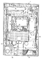
図1は、本発明に係る遊技機の一例のパチンコ遊技機1およびこれに対応して設置されたカードユニット50の正面図である。
FIG. 1 is a front view of a
カードユニット50には、カード利用可表示ランプ151が設けられており、カードユニット50が使用可能な状態にある旨が、このカード利用可表示ランプ151の点灯または点滅により遊技者に知らされる。このカードユニット50は、遊技機設置島に設置されている複数台のパチンコ遊技機1の間に挿入された状態で設置されており、左右どちらの遊技機に接続されているかが連結台方向表示器153により表示される。
The
遊技者がカード残高の記録されたプリペイドカードをカード挿入口155に挿入すると、そのプリペイドカードに記録されているカード残高が読取られる。次に、遊技者が所定の貸玉操作を行なうことにより、予め入力設定されている貸出単位額分の残高が減額されるとともに、その貸出単位額分の打玉がパチンコ遊技機1の打球供給皿3に貸出される。
When the player inserts a prepaid card in which the card balance is recorded into the card insertion slot 155, the card balance recorded in the prepaid card is read. Next, when the player performs a predetermined ball lending operation, the balance for the lending unit amount set in advance is reduced, and the hit ball for the lending unit amount is supplied to the
カードユニット50には端数表示スイッチ152が設けられている。この端数表示スイッチ152を押圧操作することにより、たとえばカード残高やエラーが発生した場合のエラーコードなどの情報がパチンコ遊技機1に設けられた情報表示器(図示省略)に表示される。図中156はカードユニット錠であり、このカードユニット錠156に所定のキーを挿入して解錠操作することにより、カードユニット50の前面側を開成できるように構成されている。
The
パチンコ遊技機1は、額縁状に形成されたガラス扉枠2を有する。このガラス扉枠2の後方には、遊技盤6が着脱自在に取付けられている。また、ガラス扉枠2の下部表面には打球供給皿3がある。打球供給皿3の下部には、打球供給皿3から溢れた玉を貯留する余剰玉受皿4と、遊技者が打球操作するための操作ノブ5とが設けられている。操作ノブ5を遊技者が操作することにより、打球供給皿3内に貯留されているパチンコ玉を1個ずつ発射することができる。遊技領域7の中央には、識別情報の一例となる特別図柄を可変開始させる可変表示装置8が設けられている。この可変表示装置8には、打玉の通過ゲート11の通過に伴って普通図柄が可変表示される普通図柄用の可変表示器10と、始動記憶表示器18とが設けられている。さらに、可変表示装置8の下方には、始動口14が構成された始動用電動役物15と、開閉板20の傾動により打玉の入賞可能な開放状態となる可変入賞球装置19とが設けられている。始動用電動役物15には、可動片が左右に設けられている。また、一般入賞口として、可変表示装置8の上部や、可変入賞球装置19の左右、遊技領域7の下方左右に入賞口24がそれぞれ設けられている。また、26は、打込まれた打玉がいずれの入賞口や可変入賞球装置にも入賞しなかった場合にアウト玉として回収するアウト口であり、25は、装飾ランプである。
The
遊技領域7の外周には枠ランプ(遊技効果LED28aおよび遊技効果ランプ28b,28c)と、賞球の払出し時に点灯する賞球ランプ51と、玉切れ中に点灯するランプ玉切れランプ52とが設けられており、遊技領域7の上部の左右にはステレオ音の音声などの効果音を発生するためのスピーカ27,27が設けられている。
A frame lamp (
可変表示装置8は、複数種類の特別図柄を可変表示可能なCRT表示機で構成されている。可変表示装置8の中央の画像表示領域9では始動入賞が発生したことを条件として複数種類の特別図柄が上から下に向かってスクロール表示される。その後、所定時間が経過して可変表示が終了した結果、大当り図柄のゾロ目が予め複数種類定められた当りラインのうちのいずれかに揃って停止表示されれば大当りとなる。大当りとなれば、可変入賞球装置19の開閉板20が傾動して大入賞口が開口する。これにより、打玉を大入賞口に入賞させることが可能な遊技者にとって有利な第1の状態に制御され、遊技状態が遊技者にとって有利な特定遊技状態(大当り状態)となる。
The
可変入賞球装置19の大入賞口内部には可変入賞球装置19に入賞した玉を検出するカウントスイッチ23が設けられている。また、大入賞口内は、特定入賞領域と通常入賞領域とに区分されており、特定入賞領域には、V入賞を検出するVカウントスイッチ22が設けられている。特定入賞領域に入賞した入賞玉はVカウントスイッチ22により検出された後、カウントスイッチ23により検出される。一方、通常入賞領域に入賞した通常入賞玉は大入賞口内においてはカウントスイッチ23のみにより検出される。可変入賞球装置19に入賞した入賞玉がカウントスイッチ23により検出される毎に15個の賞球が払出される。
A
可変入賞球装置19の第1の状態は、大入賞口に進入した打玉の数が所定個数(たとえば9個)に達した場合、または所定期間(たとえば30秒間)経過した場合のうちのいずれか早い方の条件が成立した場合に一旦終了して開閉板20が閉成する。これにより、可変入賞球装置19は打玉を入賞させることが不可能な遊技者にとって不利な第2の状態に制御される。そして、可変入賞球装置19が第1の状態となっている期間中に進入した打玉が特定入賞領域に特定入賞し、Vカウントスイッチ22により検出されたことを条件として、再度、可変入賞球装置19を第1の状態にする繰返し継続制御が実行される。この繰返し継続制御の実行上限回数はたとえば16回と定められている。繰返し継続制御において、可変入賞球装置19が第1の状態にされている状態がラウンドと呼ばれる。繰返し継続制御の実行上限回数が16回の場合には、第1ラウンドから第16ラウンドまでの16ラウンド分、可変入賞球装置19が第1の状態にされ得る。
The first state of the variable winning
可変表示装置8の左側方部分および右側方部分には、それぞれワープ入口11が設けられている。このワープ入口11に進入した打玉は、可変表示装置8の裏面側を通って下方に流下してワープ出口13から再度遊技領域7に放出される。このため、ワープ出口13から放出された打玉は、始動口14に比較的入賞しやすい状態となる。
A
ワープ入口11に進入した打玉は、ゲートスイッチ12で検出される。打玉がゲートスイッチ12で検出されることを条件として、普通図柄用可変表示器10が可変開始される。なお、普通図柄用可変表示器10が可変表示している最中にさらに打玉がゲートスイッチ12で検出された場合には、「4」を記憶数の上限として通過球が記憶されてその記憶数が通過記憶表示器(図示省略)においてLEDの点灯数により表示される。
The hit ball that has entered the
普通図柄用可変表示器10は7セグメント表示器で構成されており、普通図柄と呼ばれる識別情報が可変表示される。普通図柄用可変表示器10の表示結果が予め定められた特定の表示態様(たとえば7)となれば「当り」となる。普通図柄用可変表示器10に「当り」の表示結果が導出されると、始動用電動役物15に設けられた左右1対の可動片が1回開成する。これにより始動用電動役物15が開放状態となって打玉がより始動入賞しやすくなる。始動用電動役物15が開放状態にある際に打玉が1つ始動入賞すれば、可動片が元の位置まで閉成して打玉が始動入賞しにくい状態に戻る。また、始動用電動役物15が開放状態となってから所定の開放期間が経過すれば、始動入賞が発生しなくとも可動片が元の位置まで閉成して開放状態は終了する。なお、後述するように、確率変動状態においては、始動用電動役物15は2回開成し、かつ、1回の開成期間が延長される。
The normal
始動口14に入賞した始動入賞玉は遊技盤6に設けられた始動口スイッチ17により検出される。始動入賞玉が始動口スイッチ17で検出されると5個の賞球が払出されるとともに、その検出出力に基づいて可変表示装置8が可変開始される。可変表示装置8が可変表示中に始動口スイッチ17により検出された始動入賞は、「4」を記憶数の上限として記憶されてその記憶数が始動記憶表示器18においてLEDの点灯数により表示される。
The start winning ball won in the start opening 14 is detected by a
可変表示装置8に表示された大当りの結果が特定の確変図柄(たとえば数字図柄の「7」)により構成されるものである場合には、その大当りに基づく特定遊技状態の終了後に、通常時(通常遊技状態)に比べて大当りが発生する確率が高く変動した確率変動状態となる。以下、確変図柄による大当りを確変大当りという。通常遊技状態中に一旦、確変大当りが発生すると、少なくとも予め定められた確変継続回数(たとえば、1回、あるいは2回)大当りが発生するまで確率変動状態に継続制御される。また、確率変動状態中に確変大当りが発生すれば、その確変大当り以降、改めて確変継続回数が計数され、その後、少なくとも確変継続回数だけ大当りが発生するまで確率変動状態が継続する。そして、確変継続回数に達した大当りが確変図柄以外の非確変図柄によるものであった場合には、確率変動の生じていない通常遊技状態に戻る。
When the jackpot result displayed on the
したがって、確率変動状態の継続制御に制限を設けない場合には、少なくとも確変継続回数に達した大当りが確変大当りである限り、無制限に確率変動状態が継続する。このパチンコ遊技機1の場合には、ある程度、確率変動状態が継続すれば、一旦、確率変動状態への継続制御を終了させるべく、確率変動状態中に確変大当りが連続的に発生する回数について、上限回数が設定されている。そして、この上限回数に基づいて大当りの表示態様が非確変大当りとされた場合には、その時点で確率変動状態の継続制御が強制的に終了する。なお、確変図柄での大当りを禁止する制限が行なわれることは、リミッタの作動と呼ばれる。
Therefore, when no restriction is placed on the continuous control of the probability variation state, the probability variation state continues indefinitely at least as long as the big hit that has reached the number of times of the probability change continues is the probability change big hit. In the case of this
確率変動状態においては、普通図柄の当り確率が高くなるとともに、普通図柄の可変表示が開始してからその表示結果が導出表示されるまでの可変表示期間(変動時間)が短縮される。さらに、確率変動状態においては、普通図柄の当りによって始動用電動役物15が開成する回数が1回から2回に増加するともに、1回の開成期間が0.2秒から1.4秒に延長される。 In the probability variation state, the probability of hitting the normal symbol increases, and the variable display period (variation time) from when the normal symbol variable display starts until the display result is derived and displayed is shortened. Further, in the probability variation state, the number of times the starter electric component 15 is opened from the normal symbol hit increases from 1 to 2, and the opening period of one time increases from 0.2 seconds to 1.4 seconds. Extended.
次に、パチンコ遊技機1の背面の構造について説明する。図2は、カードユニットが隣接されたパチンコ遊技機の一部内部構造を示す全体背面図である。
Next, the structure of the back surface of the
パチンコ遊技機1の遊技盤6の裏面側には、機構板36が設けられている。この機構板36の上部には玉タンク38が設けられ、パチンコ遊技機1が遊技機設置島に設置された状態でその上方からパチンコ玉が玉タンク38に供給される。玉タンク38内のパチンコ玉は、誘導樋39を通って玉払出装置に供給される。
A
機構板36には、中継基板30を介して画像表示領域9の表示制御を行なう表示制御基板80を含む可変表示制御ユニット29、基板ケース32に覆われ遊技制御用マイクロコンピュータ等が搭載された遊技制御基板31、可変表示制御ユニット29と遊技制御基板31との間の信号を中継するための中継基板33、およびパチンコ玉の払出制御を行なう払出制御用マイクロコンピュータ等が搭載された賞球基板37が設置されている。さらに、機構板36には、モータの回転力を利用して打玉を遊技領域7に発射する打球発射装置34と、スピーカ27および遊技効果ランプ・LED28a,28b,28cに信号を送るためのランプ制御基板35が設けられている。
On the
図3は、パチンコ遊技機1の遊技盤6を背面から見た背面図である。遊技盤6の裏面には、図3に示すように、各入賞口および入賞球装置に入賞した入賞玉を所定の入賞経路に沿って導く入賞玉集合カバー40が設けられている。入賞玉集合カバー40により導かれた入賞玉は入賞玉を1個宛処理する入賞玉処理装置(図示せず)に供給される。入賞玉処理装置には入賞球検出スイッチ99(図4参照)が設けられており、入賞球検出スイッチ99の検出信号は遊技制御基板31に送られる。
FIG. 3 is a rear view of the
図4は、遊技制御基板31における回路構成の一例を示すブロック図である。図4には、制御基板として、遊技制御基板(主基板ともいう)31、賞球基板37、ランプ制御基板35、音声制御基板70、発射制御基板91および表示制御基板80が示されている。
FIG. 4 is a block diagram illustrating an example of a circuit configuration in the
賞球基板37、ランプ制御基板35、音声制御基板70、発射制御基板91および表示制御基板80には、マイクロコンピュータ等が搭載されており、たとえば、CPUやI/Oポートが設けられている。
The winning
賞球基板37には、玉払出装置97、および、カードユニット50が接続される。ランプ制御基板35には、遊技効果LED28a、賞球ランプ51、玉切れランプ52、および遊技効果ランプ28b,28cが接続される。発射制御基板91には、操作ノブ(打球操作ハンドル)5と打球ハンマー(図示省略)を駆動する駆動モータ94とが接続される。駆動モータ94の駆動力は、操作ノブ5の操作量に従って調整される。表示制御基板80には可変表示装置8(図示省略)が接続される。音声制御基板70にはスピーカ27が接続される。
A ball dispensing device 97 and a
遊技制御基板31には、遊技制御プログラムに従ってパチンコ遊技機1を制御する基本回路(遊技制御用マイクロコンピュータ)53と、スイッチ回路58と、ソレノイド回路59と、ランプ・LED回路60と、情報出力回路64と、初期リセット回路65と、アドレスデコード回路67とが設けられている。
The
基本回路53は、遊技制御用のマイクロコンピュータであり、遊技制御用のプログラム等を記憶するROM54、ワークメモリとして使用されるRAM55、制御用のプログラムに従って制御動作を行なうCPU56、I/Oポート57を含む。基本回路53は、定期的(たとえば2msec毎)にリセットされてROM54に記憶されている遊技制御プログラムを先頭から繰返し実行する。
The
初期リセット回路65は、電源投入時に基本回路53をリセットする回路である。基本回路53は、初期リセット回路65から送られてきた初期リセットパルスに応答してパチンコ遊技機1を初期化する。アドレスデコード回路67は、基本回路53から与えられるアドレス信号をデコードしてI/Oポート57のうちのいずれかのポートを選択するための信号を出力する回路である。
The initial reset circuit 65 is a circuit that resets the
スイッチ回路58は、各種スイッチからの信号を基本回路53に与える回路である。スイッチ回路58には、ゲートスイッチ12、始動口スイッチ17、Vカウントスイッチ22、カウントスイッチ23、および、入賞球検出スイッチ99が接続される。
The
情報出力回路64は、基本回路53から与えられるデータに従って、確率変動が生じて確率変動状態となっていることを示す確変情報、大当りが発生し特定遊技状態となっていることを示す大当り情報、および、始動入賞のうち画像表示領域9の可変表示に有効に使用される始動入賞の発生を示す始動入賞情報をホール管理コンピュータ等のホストコンピュータに対して出力する回路である。
The information output circuit 64 is based on the data given from the
ソレノイド回路59は、始動用電動役物15の可動片を動作させるソレノイド16および可変入賞球装置19の開閉板20を開閉するソレノイド21を基本回路53からの指令に従って駆動する回路である。
The
ランプ・LED回路60は、可変表示器(普通図柄用可変表示器)10、装飾ランプ25、および始動記憶表示器18の点灯および滅灯を制御する回路である。
The lamp / LED circuit 60 is a circuit that controls lighting and extinction of the variable display (ordinary symbol variable display) 10, the
遊技制御基板31から賞球基板37、ランプ制御基板35、音声制御基板70、および表示制御基板80には、指令情報の一例となるコマンドが送信される。
A command, which is an example of command information, is transmitted from the
遊技制御基板31から賞球基板37に伝送されるコマンドには、賞球の払出制御に関する指令情報としてのコマンドと、貸玉の払出制御に関する指令情報としてのコマンド(たとえば、玉貸し禁止コマンド、玉貸し禁止解除コマンド等)とが含まれる。
The commands transmitted from the
また、遊技制御基板31から表示制御基板80に伝送されるコマンドは表示制御コマンドであり、その表示制御コマンドのうち特別図柄に関するコマンドには、可変表示装置8の変動を開始させるための変動開始コマンドや確定図柄(予定停止図柄)を指定する確定図柄指定コマンド、変動の終了を指定する図柄確定コマンド等がある。この表示制御コマンドはそれぞれ1バイトデータからなるMODEデータとEXTデータとの2組の2バイトデータから構成されている。MODEデータは変動開始コマンドや確定図柄指定コマンド等のコマンド種別を示すデータであり、EXTデータはMODEデータにより示されたコマンド種別のうちの特定の表示制御内容を具体的に指定するデータである。
The command transmitted from the
基本回路53は、大当りあるいは入賞等の発生に基づき、所定のランプ制御コマンドをランプ制御基板35へ出力する。ランプ制御基板35では、ランプ制御コマンドに基づく上記電気的装飾部品の点灯制御が行なわれる。
The
基本回路53は、大当りあるいは入賞等の発生に基づき、所定の音声制御コマンドを音声制御基板70へ出力する。音声制御基板70では、音声制御コマンドに基づいて所定の効果音をスピーカ27から出力させる制御が行なわれる。
The
基本回路53は、入賞球検出スイッチ99の検出信号と始動口スイッチ17の検出信号、Vカウントスイッチ22の検出信号、カウントスイッチ23の検出信号に基づいて、所定個数の景品玉を払出すための賞球信号を賞球基板37に出力する。賞球基板37では、その出力されてきた賞球信号に基づいて玉払出装置を制御して所定個数の景品玉を払出すための制御を行なう。
The
具体的には、可変入賞球装置19の大入賞口に入賞した入賞玉については1個の入賞玉につきたとえば15個の景品玉が払出され、始動入賞口14に入賞した入賞玉については1個の入賞玉につきたとえば6個の景品玉が払出され、その他の入賞口24に入賞した入賞玉については入賞玉1個につきたとえば10個の景品玉が払出されるように制御される。
More specifically, for example, 15 prize balls are paid out for each winning ball for the winning ball that has won the big winning gate of the variable winning
このような3種類の個数の景品玉を払出制御するべく、遊技制御基板31は次のように制御動作を行なう。始動口スイッチ17、Vカウントスイッチ22またはカウントスイッチ23からの検出信号が入力されると、その検出信号を賞球の払出個数決定の際に用いる払出個数決定用データとして、スイッチに応じた賞球の払出個数別に一時的に内部に記憶する。その後、入賞球検出スイッチ99からの検出信号が入力されれば、その入力以前に始動口スイッチ17からの検出信号があったかどうかを払出個数決定用データを参照することによって判断し、あった場合には遊技制御基板31は賞球基板37に対し「6」の賞球個数を払出指令するための賞球指令信号を出力する。一方、入賞球検出スイッチ99からの検出信号があった場合に、それ以前にVカウントスイッチ22またはカウントスイッチ23からの検出信号があった場合には、遊技制御基板31は「15」の賞球個数の賞球指令信号を賞球基板37に出力する。さらに、入賞球検出スイッチ99からの検出信号があった場合において、それ以前に始動口スイッチ17,Vスイッチ22,カウントスイッチ23のいずれからも検出信号が入力されていなかった場合には、遊技制御基板31は「10」の賞球個数を払出し指令するための賞球指令信号を賞球基板37に出力する。
In order to control the payout of such three types of prize balls, the
遊技制御基板31から賞球基板37に送られた賞球個数信号は、賞球基板37に設けられた払出制御用マイクロコンピュータ(図示省略)により受信される。払出制御用マイクロコンピュータは、玉払出装置97を駆動して賞球個数信号により特定される個数の賞球を払出す制御を行なう。
The prize ball number signal sent from the
図5は、表示制御基板80内の回路構成を、画像表示を実現するCRT82とともに示すブロック図である。RAM101aを内蔵する表示制御用CPU101は、制御データROM102に格納されたプログラムに従って動作し、遊技制御基板31から入力バッファ回路105における入力バッファ105aを介してINT信号(ストローブ信号、割込信号ともいう)が入力されると表示制御用CPU101が割込動作状態となって表示制御用のコマンドデータを取込む。そして、取込んだ表示制御コマンドデータに従って、CRT82に表示される画像の表示制御を行なう。
FIG. 5 is a block diagram showing a circuit configuration in the display control board 80 together with a
具体的には、表示制御コマンドデータに応じた指令をVDP103に与える。VDP103は、キャラクタROM86から必要なデータを読出す。そして、VDP103は、入力したデータに従ってCRT82に表示するための画像データを生成し、その画像データをVRAM87に格納する。そして、VRAM87内の画像データは、R(赤),G(緑),B(青)信号(RGB信号)に変換され、D/A変換回路104でアナログ信号に変換されてCRT82に出力される。
Specifically, a command according to the display control command data is given to the
なお、図5には、VDP103をリセットするためのリセット回路83、VDP103に動作クロックを与えるための発振回路85、使用頻度の高い画像データを格納するキャラクタROM86、および表示制御コマンドデータを入力する入力バッファ回路105も示されている。キャラクタROM86に格納される使用頻度の高い画像データとは、たとえば、CRT82に表示される人物、動物、または、文字、図形もしくは記号等からなる画像などである。
In FIG. 5, a reset circuit 83 for resetting the
表示制御用CPU101は、後述する表示制御コマンドデータを記憶しておくためのRAM101aを内蔵しており、遊技制御基板31から表示制御コマンドを受信すると、各変動パターンにおいて予め決められている背景やキャラクタを画面上で移動表示する制御を行なう。なお、予め決められているタイミングで背景やキャラクタの切換も行なわれるが、それらも表示制御用CPU101が独自に制御する。
The
また、遊技制御基板31側の表示制御を出力する部分は、遊技制御基板31の内部から外部への情報の出力が可能であるが遊技制御基板31の外部から内部への情報の入力が不可能である不可逆性出力手段としての出力バッファ回路63により構成されている。また、表示制御基板80側において表示制御コマンドが入力される入力バッファ回路105も同様に、遊技制御基板31から表示制御基板80へ向かう方向にのみ信号の伝送を許容するが表示制御基板80側から遊技制御基板31側へ向かう信号の伝送を行なわない不可逆性を有する入力インタフェースである。従って、表示制御基板80側から遊技制御基板31側に信号が伝わる余地はなく、表示制御コマンドの伝送経路に不正改造が加えられても、不正改造によって出力される信号が遊技制御基板31側に伝わることはない。このため、遊技制御基板31と表示制御基板80との間の信号の一方向通信が担保され、表示制御コマンドの伝送経路を介して遊技制御基板31に不正な信号(データ)を入力させて不正な制御動作を行なわせる不正行為を確実に防ぐことができる。
In addition, the part that outputs display control on the
また、図4および図5に示されるように、基本回路53を含む遊技制御手段と表示制御用CPU101を含む可変表示制御手段とが別体構成された基板(遊技制御基板31,表示制御基板80)に別れて設けられているので、遊技制御手段が設けられた基板における可変表示制御に関する制御負担の一部が、可変表示制御手段が設けられた基板側に分散されるため、遊技制御手段が設けられた基板(遊技制御基板31)における可変表示制御に関する制御負担を軽減することができる。
4 and 5, the game control means including the
図6は、遊技制御基板31側の基本回路53が遊技制御に用いる各種ランダムカウンタを示す図である。図6には、C_RND1、C_RND_L、C_RND_C、C_RND_R、C_RND_RCH、およびC_RND_NRの7種類のランダムカウンタが示されている。
FIG. 6 is a diagram showing various random counters used by the
C_RND1は、始動記憶がある場合にその始動記憶に基づく特別図柄の可変表示の結果を大当りとするか否かを決定するために用いられるランダムカウンタである。このランダムカウンタは、タイマ割込毎(具体的には0.002秒毎)に1ずつ加算更新され、0から加算更新されてその上限である293まで加算更新された後再度0から加算更新される。 C_RND1 is a random counter used to determine whether or not the result of variable symbol special display based on the start-up memory is a big hit when there is a start-up memory. This random counter is incremented and incremented by 1 every timer interrupt (specifically every 0.002 seconds), incremented and updated from 0 to the upper limit of 293, and then incremented and updated again from 0. The
C_RND_L、C_RND_C、C_RND_Rは、画像表示領域9に最終的に停止表示される停止図柄(確定図柄)の種類を決定するために用いられるランダムカウンタである。
C_RND_L, C_RND_C, and C_RND_R are random counters used to determine the type of stop symbol (definite symbol) that is finally stopped and displayed in the
C_RND_Lは左図柄決定用であり、0から加算されてその上限である14まで加算されると再度0から加算される。C_RND_Lは、タイマ割込毎すなわち0.002秒毎に1ずつ加算される。なお、表示結果がはずれとなるリーチ状態を表示する場合には、このC_RND_Lによって左図柄と右図柄とが決定されることにより、リーチ図柄が定められる。 C_RND_L is for determining the left symbol. When C_RND_L is added from 0 and added up to 14 which is the upper limit thereof, it is added again from 0. C_RND_L is incremented by 1 every timer interrupt, that is, every 0.002 seconds. When a reach state in which the display result is out of place is displayed, the left symbol and the right symbol are determined by this C_RND_L, thereby determining the reach symbol.
C_RND_Cは、中図柄決定用のランダムカウンタであり、0から加算されてその上限である14まで加算されると再度0から加算される。C_RND_Cは、タイマ割込毎すなわち0.002秒毎、および、割込処理余り時間毎に1ずつ加算される。 C_RND_C is a random counter for medium symbol determination, and is added from 0 again when it is added from 0 and added up to its upper limit of 14. C_RND_C is incremented by 1 every timer interruption, that is, every 0.002 seconds, and every interruption processing surplus time.
C_RND_Rは、右図柄決定用のランダムカウンタであり、0から加算されてその上限である14まで加算された後再度0から加算される。C_RND_Rは、前述のC_RND_Cの桁上げごとに1ずつ加算される。 C_RND_R is a random symbol for determining the right symbol, is added from 0 and is added up to 14 which is the upper limit thereof, and is added again from 0. C_RND_R is incremented by one for each carry of C_RND_C described above.
C_RND_RCHおよびC_RND_NRは、変動パターンを決定するために用いられる変動パターン振分用のランダムカウンタである。特に、C_RND_RCHはリーチ状態を表示する場合に用いられるランダムカウンタであり、C_RND_NRはリーチ状態を表示しない場合に用いられるランダムカウンタである。リーチ状態の表示の必要性の有無に応じて、C_RND_RCHおよびC_RND_NRのうちいずれか一方のカウンタ値が抽出されてその値に基づいて変動パターンが定められ、その定められた変動パターンを特定可能な変動パターンデータを含む変動開始コマンドが遊技制御基板31から表示制御基板40へ出力される。C_RND_RCHの0〜7の各値に対応する変動パターンデータを指定するEXTデータと、C_RND_RCHの0〜2の各値に対応する変動パターンデータを指定するEXTデータとは、基本回路53内に記憶されている。
C_RND_RCH and C_RND_NR are random counters for distributing the fluctuation pattern used to determine the fluctuation pattern. In particular, C_RND_RCH is a random counter used when the reach state is displayed, and C_RND_NR is a random counter used when the reach state is not displayed. Depending on whether or not the reach state needs to be displayed, either one of the counter values of C_RND_RCH and C_RND_NR is extracted, and the variation pattern is determined based on the extracted counter value, and the variation that can identify the determined variation pattern A variation start command including pattern data is output from the
C_RND_RCHは0から加算されてその上限である7まで加算された後再度0から加算される。また、C_RND_NRは0から加算されてその上限である2まで加算された後再度0から加算される。C_RND_RCHおよびC_RND_NRは、前述したタイマ割込毎すなわち0.002秒毎、および、割込処理余り時間毎に1ずつ加算される。 C_RND_RCH is added from 0 and added to 7 which is the upper limit thereof, and then added again from 0. Also, C_RND_NR is added from 0 and added to 2 which is the upper limit thereof, and then added again from 0. C_RND_RCH and C_RND_NR are incremented by 1 for each timer interrupt described above, that is, for every 0.002 seconds, and for each extra interrupt processing time.
図7は、始動記憶がある場合にその始動記憶に基づく特別図柄の可変表示の結果を大当りとするか否かを決定する処理手順を説明するためのフローチャートである。 FIG. 7 is a flowchart for explaining a processing procedure for determining whether or not the result of variable display of a special symbol based on the start memory is a big hit when there is a start memory.
始動入賞があれば、C_RND1のカウント値が抽出される。C_RND1の抽出値は特別図柄判定用バンクに格納される。ここで、特別図柄判定用バンクは、始動入賞に応じて抽出されたC_RND1の抽出値のデータを一時的に格納するための記憶領域をいい、基本回路53のRAM55の作業領域に設けられている。始動入賞は最大4つまで記憶されるため、特別図柄判定用バンクは、バンク0〜バンク3の4つの記憶領域を有するシフトレジスタにより構成されている。特別図柄判定用バンクにおいては、始動入賞が検出された時点で、特別図柄判定用バンク0,1,2,3の順序で、始動入賞に対応するC_RND1の抽出値のデータが記憶されて行く。
If there is a start win, the count value of C_RND1 is extracted. The extracted value of C_RND1 is stored in the special symbol determination bank. Here, the special symbol determination bank is a storage area for temporarily storing data of the extracted value of C_RND1 extracted in accordance with the start winning, and is provided in the work area of the RAM 55 of the
具体的に、始動入賞に応じたC_RND1の抽出値は、最大4つ記憶されるが、最も古いタイミングでの抽出値が特別図柄判定用バンク0に記憶され、始動入賞に応じて、バンク1,2,3の順に抽出値が記憶されて行く。特別図柄判定用バンク0〜3のうちのバンク0に記憶されている抽出値が、大当りを発生させるか否かの判定に用いられる。そして、バンク0の判定が済むと、バンク0の記憶データがクリアされるとともに、バンク1,2,3のそれぞれの記憶データが、1バンクずつバンク0に向けてシフトされる。そして、そのような大当りの判定とデータのシフトとが繰返し実行されることにより、始動入賞記憶に応じた大当りの判定が行なわれるのである。
Specifically, the maximum four extracted values of C_RND1 corresponding to the start winning are stored, but the extracted value at the oldest timing is stored in the special
なお、始動入賞が検出されるのと同時にC_RND_Lのカウント値も抽出され、その抽出値は左図柄判定用バンクに格納される。左図柄判定用バンクについても特別図柄判定用バンクと同様に基本回路53のRAM55の作業領域に設けられており、左図柄判定用バンク0〜左図柄判定用バンク3の4つの記憶領域を有するシフトレジスタにより構成されている。そして、左図柄判定用バンクにおいては、始動入賞が検出された時点で、左図柄判定用バンク0,1,2,3の順序で、始動入賞に対応するC_RND_Lの抽出値のデータが記憶されて行く。
Note that the count value of C_RND_L is also extracted at the same time when the start winning is detected, and the extracted value is stored in the left symbol determination bank. The left symbol determination bank is also provided in the work area of the RAM 55 of the
また、同様に、C_RND_Cのカウント値およびC_RND_Rの抽出も、それぞれに対応して設けられたバンク0〜3に格納される。
Similarly, the count value of C_RND_C and the extraction of C_RND_R are also stored in the
次に、特別図柄判定用バンクに格納された抽出値を判定するための大当り判定用の特別図柄判定値が設定される。ここで、高確率時(確率変動状態)でない通常時(通常遊技状態)においては、特別図柄判定値として「7」が設定される。一方、高確率時では、特別図柄判定値として「7」,「11」,「79」の3つが設定される。 Next, a special symbol determination value for jackpot determination for determining the extracted value stored in the special symbol determination bank is set. Here, “7” is set as the special symbol determination value in the normal time (normal game state) other than the high probability time (probability fluctuation state). On the other hand, at the time of high probability, “7”, “11”, and “79” are set as special symbol determination values.
次に、設定された特別図柄判定値と抽出値とが比較され、通常時では、抽出値が「7」のときには大当りとすることが決定され、それ以外の時にははずれとすることが決定される。一方、高確率時では、抽出値が「7」,「11」,「79」のうちのいずれかのときには大当りとすることが決定され、それ以外の時にははずれとすることが決定される。 Next, the set special symbol determination value and the extracted value are compared. In normal times, when the extracted value is “7”, it is determined to be a big hit, and otherwise it is determined to be out of place. . On the other hand, at a high probability, when the extracted value is “7”, “11”, or “79”, it is determined to be a big hit, and at other times, it is determined to be out of place.
大当りとすることが決定された場合には、左図柄判定用バンクに格納されているC_RND_Lの値が参照され、ゾロ目で停止させる大当り図柄がその抽出値に基づいて決定される。一方、はずれとすることが決定された場合には、C_RND_C、C_RND_Rの値が抽出され、それらの抽出値と左図柄判定用バンクに格納されているC_RND_Lとに基づいて画像表示領域9に最終的に停止させるはずれ図柄が決定される。ここで、この決定されたはずれ図柄が偶然ゾロ目の図柄であった場合には、C_RND_Cの抽出値に「1」が加算され、強制的にはずれ図柄とされる。
When it is determined that the jackpot is determined, the value of C_RND_L stored in the left symbol determination bank is referred to, and the jackpot symbol to be stopped at the doublet is determined based on the extracted value. On the other hand, if it is determined to be out of place, the values of C_RND_C and C_RND_R are extracted, and finally the
図7を用いて説明した以上の処理は、特別図柄の可変表示を開始させる前に事前に行なわれる。 The above processing described with reference to FIG. 7 is performed in advance before starting the variable symbol special display.
次に、基本回路53により実行される処理の一部をフローチャートを参照して説明する。
Next, a part of the processing executed by the
図8は、基本回路53により実行される遊技制御メイン処理および割り込み処理を示すフローチャートである。図8においては、(a)に遊技制御メイン処理が示され、(b)に割り込み処理が示されている。
FIG. 8 is a flowchart showing game control main processing and interrupt processing executed by the
図8の(a)を参照して、遊技制御メイン処理においては、まず、スタックポインタの指定アドレスをセットするためのスタックセット処理が行なわれる(S1)。次いで、初期化処理が行なわれる(S2)。初期化処理では、RAM55にエラーが含まれているか判定され、エラーが含まれている場合には、RAM55を初期化することおよび各種フラグの初期設定などの処理が行なわれる。さらに、初期化処理では、後述する割り込み処理を実行するタイミングを規定するタイマ割り込み時間(たとえば0.002秒)をCPU56に設定する処理がなされる。これにより、電源投入等によるリセット後の最初の割り込み処理の実行タイミング規定のための計時が開始される。
Referring to (a) of FIG. 8, in the game control main process, first, a stack setting process for setting a designated address of the stack pointer is performed (S1). Next, initialization processing is performed (S2). In the initialization process, it is determined whether an error is included in the RAM 55. If an error is included, the RAM 55 is initialized and various flags are initialized. Further, in the initialization process, a process of setting a timer interruption time (for example, 0.002 seconds) that defines timing for executing an interruption process, which will be described later, to the
次に、停止図柄を決定する等のための表示用乱数更新処理が行なわれる(S3)。このパチンコ遊技機1においては、可変表示装置8の可変表示での特別図柄の停止図柄が乱数(ランダムカウンタのカウンタ値)に基づいて決定される。このS3では、そのように停止図柄を決定するための表示用乱数が更新される。表示用乱数更新処理は、無限ループにより繰返し実行され続けるが、後述する割り込み処理が起動された場合には、表示用乱数更新処理を構成するプログラムのうちの実行中の位置で一時停止され、その割り込み処理が終了すると一時停止したプログラムの位置から実行が再開される。
Next, a display random number update process for determining a stop symbol is performed (S3). In the
次に、図8の(b)を参照して、割り込み処理は、CPU56により管理されるタイマ割り込み用のタイマの計時値が設定値(S2またはS13で設定されるタイマ割り込み時間)になるごとに実行が開始される。
Next, referring to (b) of FIG. 8, the interrupt process is performed every time the timer value for the timer interrupt managed by the
割り込み処理においては、まず、ランプ制御基板35および音声制御基板70に音声発生やLED点灯制御用の所定のコマンドを送信するための処理が行なわれるとともに、情報出力回路64を介してホール管理用コンピュータに大当り情報、始動情報、確率変動情報などのデータを送信するためのデータ出力処理が行なわれる(S4)。次に、パチンコ遊技機1の内部に備えられている自己診断機能によって種々の異常診断をし、その結果に応じて必要ならば警報を発生させるためのエラー処理が行なわれる(S5)。次に、遊技制御に用いられる各種の判定用乱数を示す各ランダムカウンタを更新する判定用乱数更新処理が行なわれる(S6)。
In the interruption process, first, a process for transmitting a predetermined command for generating a sound or controlling the LED lighting to the
次に、特別図柄プロセス処理が行なわれる(S7)。特別図柄プロセス処理では、複数種類の処理のうちの1つが特別図柄プロセスフラグの値に従って選択されて実行される。そして、特別図柄プロセスフラグの値は、遊技状態に応じて各処理中において更新される。次に、普通図柄プロセス処理が行なわれる(S8)。普通図柄プロセス処理では、7セグメントLEDによる普通図柄用可変表示器10を所定の順序で制御するための普通図柄プロセスフラグに従って該当する処理が選び出されて実行される。そして、普通図柄プロセスフラグの値は、遊技状態に応じて各処理中に更新される。
Next, a special symbol process is performed (S7). In the special symbol process, one of a plurality of types of processing is selected and executed according to the value of the special symbol process flag. The value of the special symbol process flag is updated during each process according to the gaming state. Next, a normal symbol process is performed (S8). In the normal symbol process, a corresponding process is selected and executed in accordance with a normal symbol process flag for controlling the normal
次に、S3と同様の表示用乱数更新処理が行なわれる(S10)。次に、賞球基板37との間の入賞球信号処理が行なわれる(S11)。すなわち、基本回路53は、賞球基板37より賞球数要求信号が入力されると、賞球基板37に対して出力すべき賞球コマンド(賞球数指定信号)を選択する。次に、選択した賞球コマンドを出力するための賞球コマンド出力処理が行なわれる(S12)。賞球基板37は、この賞球数指定信号に基づいて玉払出装置97を駆動制御する。
Next, a display random number update process similar to S3 is performed (S10). Next, winning ball signal processing with the winning
次に、タイマ割り込み時間設定処理が行なわれる(S13)。S13においては、前述したようなタイマ割り込み時間(たとえば0.002秒)をS2の場合と同様に設定する処理が実行される。S13の後、この割り込み処理が終了する。これにより、この割り込み処理の終了時にS13によってタイマ割り込み時間が設定され、次の割り込み処理の実行タイミングを規定するための計時が開始されることとなる。したがって、割り込み処理が終了するごとにタイマ割り込みのための時間が計時され、その後タイマ割り込み時間が経過するごとに割り込み処理が実行されることとなる。この割り込み処理が終了すると、前述したメイン処理のプログラムの実行が、一時停止していた位置から再開される。 Next, a timer interrupt time setting process is performed (S13). In S13, a process for setting the timer interruption time (for example, 0.002 seconds) as described above is performed in the same manner as in S2. After S13, this interrupt process ends. As a result, at the end of this interrupt process, the timer interrupt time is set by S13, and the timing for defining the execution timing of the next interrupt process is started. Therefore, the time for timer interruption is counted every time the interruption process is completed, and the interruption process is executed every time the timer interruption time elapses thereafter. When this interrupt process is completed, the execution of the main process program described above is resumed from the position where it was temporarily stopped.
図9は特別図柄プロセス処理を説明するためのフローチャートである。特別図柄プロセス処理は、図8(b)のS7で実行される処理である。この特別図柄プロセス処理においては、S300aのカウントスイッチ処理、S300bのVスイッチ処理、S300cの特別図柄始動口スイッチ処理が順次実行された後、特別図柄プロセスフラグの値に応じてS300〜S307のうちのいずれかの処理が実行された後、S308の表示制御データ処理が実行される。この特別図柄プロセス処理が実行されることにより、特別図柄の変動が制御されるとともに、大当り状態における制御が行なわれる。ここで、特別図柄プロセスフラグとは、各特別図柄の可変表示を実行する際に実行するプロセスを指定するフラグをいう。 FIG. 9 is a flowchart for explaining the special symbol process. The special symbol process is a process executed in S7 of FIG. In this special symbol process, after the count switch process of S300a, the V switch process of S300b, and the special symbol start port switch process of S300c are sequentially executed, one of S300 to S307 is performed according to the value of the special symbol process flag. After any process is executed, the display control data process of S308 is executed. By executing this special symbol process, the variation of the special symbol is controlled and the control in the big hit state is performed. Here, the special symbol process flag is a flag that specifies a process to be executed when variable display of each special symbol is executed.
まず、カウントスイッチ処理(S300a)では、カウントスイッチ23の出力信号の状態を監視し、可変入賞球装置19に対する入賞があったか否かの判定が行なわれる。次に、Vスイッチ処理(S300b)では、Vカウントスイッチ22の出力信号の状態を監視し、特定入賞領域に対する入賞があったか否かの判定が行なわれる。次に、特別図柄始動口スイッチ処理(S300c)では、始動口スイッチ17の出力信号の状態を監視し、始動口14に対する入賞があったか否かの判定が行なわれる。特別図柄始動口スイッチ処理の詳細については、図10を用いて後述する。
First, in the count switch process (S300a), the state of the output signal of the
図9には、特別図柄プロセスフラグ値が各ステップS300〜S307の左肩にPF1〜PF8として示されている。特別図柄の可変表示動作は、複数のプロセスに分けられており、特別図柄プロセスフラグのデータにより指定されるプロセスに応じた状態に制御される。 In FIG. 9, special symbol process flag values are shown as PF1 to PF8 on the left shoulders of steps S300 to S307. The special symbol variable display operation is divided into a plurality of processes, and is controlled to a state corresponding to the process designated by the data of the special symbol process flag.
特別図柄変動待ち処理(S300)は、始動入賞があるか否か(始動記憶があるか否か)を判定し、始動入賞がない場合には客待ちのための待機用の画面であるデモンストレーション画面(デモ画面)を表示させるための指令情報を設定し、始動入賞がある場合には特別図柄プロセスフラグを更新して特別図柄判定処理に移行可能とする処理である。詳細については、図11を用いて後述する。 The special symbol variation waiting process (S300) determines whether or not there is a start prize (whether or not there is a start memory), and when there is no start prize, a demonstration screen which is a standby screen for waiting for a customer The command information for displaying the (demo screen) is set, and when there is a start winning, the special symbol process flag is updated to enable the transition to the special symbol determination process. Details will be described later with reference to FIG.
特別図柄判定処理(S301)は、始動記憶に関連するデータを抽出し、大当りとするか否かなどを事前決定する処理である。詳細については、図12を用いて後述する。 The special symbol determination process (S301) is a process of extracting data related to the start memory and determining in advance whether or not to make a big hit. Details will be described later with reference to FIG.
特別図柄設定処理(S301a)は、停止図柄を設定するための処理である。詳細については図13を用いて後述する。 The special symbol setting process (S301a) is a process for setting a stop symbol. Details will be described later with reference to FIG.
図柄変動設定処理(S302)は、変動パターンを設定するための処理である。詳細については図14を用いて後述する。 The symbol variation setting process (S302) is a process for setting a variation pattern. Details will be described later with reference to FIG.
図柄確定設定処理(S303)は、可変表示を終了させる(特別図柄の変動を終了させる)ための図柄確定コマンドを表示制御基板80に対して出力する処理である。詳細については図15を用いて後述する。 The symbol determination setting process (S303) is a process of outputting a symbol determination command for ending the variable display (to end the special symbol change) to the display control board 80. Details will be described later with reference to FIG.
大当り表示処理(S304)は、大当りが発生したことを遊技者に報知するためのコマンドを表示制御基板80に対して出力する処理である。詳細については説明を省略する。 The jackpot display process (S304) is a process of outputting a command for notifying the player that a jackpot has occurred to the display control board 80. Details are omitted here.
大入賞口開放開始処理(S305)は、可変入賞球装置19のアタッカ(開閉板20)を開放させるとともに、表示制御基板80に対して大当り開始用の表示制御コマンドを出力する処理である。詳細については説明を省略する。
The big winning opening opening process (S305) is a process of opening the attacker (opening / closing plate 20) of the variable winning
大入賞口開放中処理(S306)は、ラウンド数表示のための表示制御コマンドを表示制御基板80に対して出力し、さらに、1ラウンド中の開放時間を計時するとともに1ラウンド中の入賞玉数をカウントし(10カウント)、V入賞が発生したか否かを判定する処理である。なお1ラウンドが終了した場合には、この大入賞口開放中処理によって大入賞口を開放させるためのソレノイド21が非励磁状態とされて可変入賞球装置19が閉成状態となる。詳細については説明を省略する。
The large winning opening opening process (S306) outputs a display control command for displaying the number of rounds to the display control board 80, and also counts the opening time during one round and the number of winning balls during one round. Is counted (10 counts) to determine whether or not a V prize has occurred. When one round is completed, the
大当り終了処理(S307)は、大当り状態を終了させる際に実行される処理であり、この処理により確率変動状態とするか否かが決定される。詳細については、図16を用いて後述する。 The big hit end process (S307) is a process executed when the big hit state is ended, and it is determined by this process whether or not the probability variation state is set. Details will be described later with reference to FIG.
表示制御データ処理(S308)は、上記各種処理(S300〜S307)において設定された表示制御用のコマンドデータを表示制御基板80へ出力する処理である。この表示制御データ処理(S308)については、特別図柄プロセスフラグの値如何にかかわらず、特別図柄プロセス処理が実行された際には常に実行される。表示制御データ処理の詳細については、図17を用いて後述する。 The display control data process (S308) is a process for outputting the display control command data set in the various processes (S300 to S307) to the display control board 80. This display control data processing (S308) is always executed when the special symbol process is executed regardless of the value of the special symbol process flag. Details of the display control data processing will be described later with reference to FIG.
図10は、特別図柄始動口スイッチ処理を説明するためのフローチャートである。特別図柄始動口スイッチ処理においては、まず、始動口スイッチ17をチェックする処理が行なわれる(SP0a)。これにより、始動口スイッチ17が始動入賞玉を検出した状態(ON状態)であるか否かがチェックされる。次に、始動口スイッチ17のチェックの結果、始動口スイッチ17がON状態であるか否かが判断される(SP0b)。始動口スイッチ17がON状態ではないと判断された場合は、この特別図柄始動口スイッチ処理が終了する。一方、始動口スイッチ17がON状態であると判断された場合は、入賞記憶カウンタのデータをロードする処理がなされる(SP1)。ここで、入賞記憶カウンタとは、始動入賞数を記憶するためのカウンタであって、後述するSP9により加算更新され、後述するSE11により減算更新される。この入賞記憶カウンタは、「0」を初期値とし、「4」を最大値としてカウントされる。
FIG. 10 is a flowchart for explaining the special symbol start port switch process. In the special symbol start port switch process, first, a process of checking the
次に、ロードした入賞記憶カウンタのカウンタ値が始動入賞記憶の最大値である「4」(個)であるか否かの判断がなされる(SP2)。ここで、最大値であると判断された場合は、始動入賞記憶の最大値を超える入賞であるため、始動入賞を無効とするために、この特別図柄始動口スイッチ処理が終了する。一方、最大値ではないと判断された場合は、大当り判定用カウンタ値(C_RND1のカウンタ値)の格納アドレス(前述した特別図柄判定用バンクの空きバンクのアドレス)を設定する処理がなされる(SP3)。RAM55には大当り判定用カウンタ値を格納するための特別図柄判定用バンクの領域が設けられており、ここでは大当り判定用カウンタ値を格納するためのアドレスが指定されるのである。次に、大当り判定用カウンタ(C_RND1)のカウンタ値を抽出し、その抽出値をSP3で設定したアドレスに格納する処理がなされる(SP4)。 Next, it is determined whether or not the counter value of the loaded winning memory counter is “4” (pieces) which is the maximum value of the starting winning memory (SP2). Here, when it is determined that the maximum value is reached, the winning exceeds the maximum value of the start winning memory, and thus the special symbol start opening switch processing is terminated in order to invalidate the starting winning. On the other hand, if it is determined that the value is not the maximum value, a process for setting the storage address of the jackpot determination counter value (the counter value of C_RND1) (the address of the empty bank of the special symbol determination bank described above) is performed (SP3). ). The RAM 55 is provided with a special symbol determination bank area for storing the jackpot determination counter value. Here, an address for storing the jackpot determination counter value is designated. Next, the counter value for the big hit determination counter (C_RND1) is extracted, and the extracted value is stored in the address set in SP3 (SP4).
次に、大当り図柄決定のために用いられる左図柄決定用カウンタ値(C_RND_Lのカウンタ値)の格納アドレス(前述した左図柄判定用バンクの空きバンクのアドレス)を設定する処理がなされる(SP5)。RAM55には左図柄決定用カウンタ値を格納するための領域が設けられており、ここでは左図柄決定用カウンタ値を格納するためのアドレスが指定されるのである。次に、左図柄決定用カウンタ(C_RND_L)のカウンタ値を抽出し、その抽出値をSP5で設定したアドレスに格納する処理がなされる(SP6)。 Next, a process of setting a storage address of the left symbol determination counter value (counter value of C_RND_L) used for determining the big hit symbol (the address of the empty bank of the left symbol determination bank described above) is performed (SP5). . The RAM 55 is provided with an area for storing the left symbol determination counter value. Here, an address for storing the left symbol determination counter value is designated. Next, the counter value for the left symbol determination counter (C_RND_L) is extracted, and the extracted value is stored in the address set in SP5 (SP6).
次に、その他のカウンタ値、具体的には、C_RND_C,C_RND_Rのカウンタ値の格納アドレス(前述したC_RND_C用のバンク,C_RND_R用のバンクのそれぞれの空きバンクのアドレス)を設定する処理がなされる(SP7)。RAM55には、このようなその他のカウンタ値を格納するための領域が設けられており、ここではそのようなカウンタ値を格納するためのアドレスが指定されるのである。次に、その他のカウンタ値、具体的には、C_RND_C,C_RND_Rのカウンタ値をそれぞれ抽出し、それらの抽出値をSP7で設定したアドレスにそれぞれ格納する処理がなされる(SP8)。次に、入賞記憶カウンタの値を1だけ加算更新する処理がなされる(SP9)。これにより、SP3〜SP8の始動入賞記憶のための処理の完了に応じて、始動入賞記憶が加算更新される。SP9の後、この特別図柄始動口スイッチ処理が終了する。 Next, processing for setting other counter values, specifically, the storage addresses of the counter values of C_RND_C and C_RND_R (the addresses of the above-mentioned banks for C_RND_C and C_RND_R, respectively) is performed ( SP7). The RAM 55 is provided with an area for storing such other counter values. Here, an address for storing such counter values is designated. Next, other counter values, specifically, C_RND_C and C_RND_R counter values are extracted and stored in the addresses set in SP7 (SP8). Next, a process of adding and updating the value of the winning memory counter by 1 is performed (SP9). As a result, the start winning memory is added and updated in accordance with the completion of the processing for starting winning memories at SP3 to SP8. After SP9, the special symbol start port switch process ends.
図11は、特別図柄変動待ち処理を説明するためのフローチャートである。特別図柄変動待ち処理においては、まず、入賞(始動記憶)があるか否かが判断される(SB1)。入賞(始動記憶)が存在しない場合には、所定時間が経過したか否かが判断される(SB2)。前回、デモ画面の切換表示をしてから所定時間が経過していない場合には、特別図柄プロセスフラグが更新されることなく処理が終了する。一方、所定時間が経過している場合には、デモ画面の切換がなされる(SB3)。具体的には、デモ画面を切換えるための表示制御コマンドが設定される。このパチンコ遊技機1では、所定時間が経過した後に始動記憶が存在せず特別図柄を変動させることのできない状態が所定時間以上継続した場合には、画像表示領域9に所定のデモ画面が表示される。このデモ画面としては、図21を用いて後述するように画面1と画面2の2種類が用意されており、始動記憶が存在しない状態が継続する限り、所定時間が経過する毎に後に両画面に交互に切換えられる。その後、始動記憶が存在する状態となれば、SB1でYESの判断がなされ、特別図柄プロセスフラグの値が特別図柄判定処理を実行できる値「2」に更新され(SB4)、処理が終了する。
FIG. 11 is a flowchart for explaining the special symbol variation waiting process. In the special symbol variation waiting process, it is first determined whether or not there is a winning (starting memory) (SB1). If there is no winning (starting memory), it is determined whether or not a predetermined time has elapsed (SB2). If the predetermined time has not elapsed since the last time the demo screen was switched and displayed, the process ends without updating the special symbol process flag. On the other hand, if the predetermined time has elapsed, the demo screen is switched (SB3). Specifically, a display control command for switching the demonstration screen is set. In this
なお、SB3で設定された表示制御コマンドは、特別図柄変動待ち処理の終了後に移行する表示制御データ処理(S308)において表示制御基板80へ出力される。 The display control command set in SB3 is output to the display control board 80 in the display control data process (S308) that shifts after the special symbol variation waiting process is completed.
図12は、特別図柄判定処理を説明するためのフローチャートである。特別図柄判定処理においては、まず、確率変動フラグがオンされているか、すなわち、パチンコ遊技機1が高確率状態に制御されている最中であるか否かが判断される(SA1)。高確率状態に制御されている場合には、高確率時すなわち確変状態にある場合の特別図柄判定値データを大当り判定用データとしてセットする処理を行なわれる(SA3)。確変状態にある場合の特別図柄判定値データとは、具体的には、「7」,「11」,「79」である。
FIG. 12 is a flowchart for explaining the special symbol determination process. In the special symbol determination process, it is first determined whether the probability variation flag is turned on, that is, whether the
一方、高確率状態に制御されていない場合には、低確率時すなわち高確率状態にない通常時の特別図柄判定値データを大当り判定用データとしてセットする処理が行なわれる(SA2)。通常時の特別図柄判定値データとは、具体的には「7」である。 On the other hand, when not controlled to the high probability state, the special symbol determination value data at the time of low probability, that is, not in the high probability state is set as big hit determination data (SA2). Specifically, the special symbol determination value data at the normal time is “7”.
SA2またはSA3の後、大当りフラグをクリアする処理が行なわれる(SA4)。これにより、前回の大当り状態の記憶がクリアされる。次に、特別図柄判定用バンク0に記憶された大当り判定用乱数が、SA2またはSA3でセットした特別図柄判定値データと一致するか否かが判断される(SA5)。SA5において、高確率時特別図柄判定値データにより判定がなされる場合には、複数の特別図柄判定値のうちの選択された1つの特別図柄判定値データを用いて1回の判定が行なわれる。高確率時特別図柄判定値データを構成する複数の特別図柄判定値のそれぞれは、判定に用いられる順序が予め定められており、最初の順番の特別図柄判定値から順にSA5での判断に用いられる。SA5での判断に用いられる特別図柄判定値が、後述するSA8の処理により順次更新されて行くことにより、高確率時特別図柄判定値データのすべてについての判定が行なわれる。
After SA2 or SA3, processing for clearing the big hit flag is performed (SA4). As a result, the memory of the previous big hit state is cleared. Next, it is determined whether or not the jackpot determination random number stored in the special
SA5により特別図柄判定用バンク0のC_RND1の記憶データが特別図柄判定値と一致すると判断された場合は、大当りを発生させる場合であり、後述するSA6に進む。一方、SA5により特別図柄判定用バンク0のC_RND1の記憶データが特別図柄判定値ではないと判断された場合は、次の順序の特別図柄判定値のデータをSA5での判定に用いられる特別図柄判定値として設定する処理がなされる(SA8)。ここで、低確率時特別図柄判定値データおよび高確率時特別図柄判定値データのそれぞれは、特別図柄判定値の他に判定終了コードと呼ばれるデータを含んでいる。低確率時特別図柄判定値データがSA5での判定のために設定されている場合には、SA8において、常に判定終了コードが設定される。一方、高確率時特別図柄判定値データがSA5での判定のために設定されている場合にSA5で最後の順序の特別図柄判定値を用いた判定がなされた後には、SA8において、判定終了コードが設定される。
When it is determined by SA5 that the stored data of C_RND1 in the special
SA8の後、SA8で設定された特別図柄判定値のデータが判定終了コードであるか否かの判断がなされる(SA9)。ここで判定終了コードではないと判断された場合には、SA8により設定された次の特別図柄判定値を用いて大当りの判定を行なうため、SA5に戻る。これにより、高確率時の場合には、複数の特別図柄判定値による大当りの判定が繰返し行なわれる。 After SA8, it is determined whether or not the special symbol determination value data set in SA8 is a determination end code (SA9). If it is determined that the code is not the determination end code, the process returns to SA5 in order to determine the big hit using the next special symbol determination value set in SA8. Thereby, in the case of a high probability, the big hit determination by a plurality of special symbol determination values is repeatedly performed.
SA5により特別図柄判定用バンク0のC_RND1の記憶データが特別図柄判定値と一致すると判断された場合は、大当りを発生させるため、大当りフラグを設定する処理がなされる(SA6)。次にリーチフラグを設定する処理がなされる(SA7)。ここでリーチフラグとは、リーチ状態が表示される場合に設定されるフラグをいう。このリーチフラグの設定により、最終的な表示結果が導出表示される前には、リーチ状態が表示される。SA7でリーチフラグが設定された後は、特別図柄プロセスフラグの値が特別図柄設定処理に移行できる値に更新され(SA12)、処理が終了する。
If it is determined by SA5 that the stored data of C_RND1 in the special
SA9により判定終了コードであると判断された場合には、特別図柄判定値を用いた大当りの判定がすべて終了し、はずれにすることが決定される。この場合には、特別図柄プロセスフラグの値が特別図柄設定処理に移行できる値に更新され(SA12)、処理が終了する。 If it is determined by SA9 that the code is the determination end code, all the big hit determinations using the special symbol determination value are ended and it is determined to be out of place. In this case, the value of the special symbol process flag is updated to a value that can be transferred to the special symbol setting process (SA12), and the process ends.
図13は特別図柄設定処理を説明するためのフローチャートである。この特別設定処理においては、まず、リミッタ作動フラグがセットされているか否かが判断される(SE1)。ここで、リミッタ作動フラグは、確率変動のリミッタを作動させる必要が生じた場合に後述の図16のSD13において設定されるフラグである。リミッタ作動フラグがセットされている場合には、確変大当りが発生しないように制御する必要があり、このためにリミッタ作動時の特別図柄テーブルが設定される(SE3)。一方、リミッタ作動フラグがセットされていない場合には、確変大当りが発生しないように制御する必要がないために、通常時の特別図柄テーブルが設定される(SE2)。 FIG. 13 is a flowchart for explaining the special symbol setting process. In this special setting process, first, it is determined whether or not the limiter operation flag is set (SE1). Here, the limiter operation flag is a flag that is set in SD13 of FIG. 16 to be described later when it becomes necessary to operate the probability variation limiter. When the limiter operation flag is set, it is necessary to control so that the probability variation big hit does not occur. For this purpose, a special symbol table at the time of limiter operation is set (SE3). On the other hand, when the limiter operation flag is not set, it is not necessary to perform control so that the probability variation big hit does not occur, and therefore, a special symbol table at normal time is set (SE2).
ここで、特別図柄テーブルは、停止図柄決定用のランダムカウンタ(C_RND_L、C_RND_C、C_RND_R)のカウント値と特別図柄の種類との対応関係を定めたテーブルである。通常時の特別図柄テーブルには、確変図柄を含む全種類の特別図柄が停止図柄決定用のランダムカウンタのカウント値に対応づけされている。一方、リミッタ作動時の特別図柄テーブルには、確変図柄を除く特別図柄が停止図柄決定用のランダムカウンタのカウント値に対応づけされている。 Here, the special symbol table is a table that defines a correspondence relationship between the count value of the random symbol for determining the stop symbol (C_RND_L, C_RND_C, C_RND_R) and the type of the special symbol. In the special symbol table at the normal time, all kinds of special symbols including the probability variation symbol are associated with the count value of the random counter for determining the stop symbol. On the other hand, in the special symbol table at the time of the limiter operation, special symbols excluding the probability variation symbols are associated with the count value of the random counter for determining the stop symbol.
SE2またはSE3で特別図柄テーブルが設定された後、その設定された特別図柄テーブルから特別図柄データが抽出される(SE4)。具体的には、大当りフラグが設定されている場合には、すでに左図柄判定用バンク0に格納されているC_RND_Lの抽出値と、SE2またはSE3で設定された特別図柄テーブルとに基づいて、大当り図柄が決定される。一方、大当りフラグが設定されていない場合には、C_RND_C、C_RND_Rのそれぞれのカウンタ値格納用のバンク0の抽出値およびすでに左図柄判定用バンク0に格納されているC_RND_Lの抽出値と、通常時の特別図柄テーブルとに基づいて、はずれ図柄の予定停止図柄が決定される。このSE4で決定された予定停止図柄は、可変表示結果として最終的に導出表示される確定図柄とされる。
After the special symbol table is set in SE2 or SE3, special symbol data is extracted from the set special symbol table (SE4). Specifically, when the jackpot flag is set, the jackpot is based on the extracted value of C_RND_L already stored in the left
次に、SE4で定められた確定図柄データのうちの左図柄の予定停止図柄と右図柄の予定停止図柄とが一致しているか否かの判断がなされる(SE5)。これらの予定停止図柄が一致している場合には、リーチフラグが設定され(SE6)、その後、SE7に進む。一方、これらの予定停止図柄が一致していない場合には、リーチフラグが設定されず、そのままSE7に進む。 Next, it is determined whether or not the scheduled stop symbol of the left symbol and the scheduled stop symbol of the right symbol in the confirmed symbol data determined in SE4 match (SE5). If these scheduled stop symbols match, the reach flag is set (SE6), and then the process proceeds to SE7. On the other hand, if these scheduled stop symbols do not match, the reach flag is not set, and the process proceeds to SE7 as it is.
次に、SE7では、特別図柄判定用バンク、左図柄判定用バンク、およびその他の判定用バンク(中図柄判定用バンクおよび右中図柄判定用バンク)のデータをシフトさせる処理が実行される。すなわち、バンク0のデータが廃棄され、バンク1〜3のそれぞれのデータが1つ先のバンクにシフトされる。これにより、たとえば、特別図柄判定用バンクの場合には、次のデータ(新たにバンク0にシフトされたC_RND1の抽出値)が大当り判定の処理に用いられる状態になる。
Next, in SE7, a process of shifting data of the special symbol determination bank, the left symbol determination bank, and the other determination banks (the middle symbol determination bank and the right middle symbol determination bank) is executed. That is, the data in
次に、特別図柄判定用バンク3の記憶データがクリアされる(SE8)。これは、SE7によるデータのシフトにより、データのシフト前の特別図柄判定用バンク3の記憶データを保持する必要がなくなったためであり、これにより、新たな始動入賞に応じたC_RND1の抽出値を特別図柄判定用バンク3に記憶させることが可能になる。
Next, the data stored in the special
次に、左図柄判定用バンク3の記憶データをクリアする処理がなされる(SE9)。これは、SE7によるデータのシフトにより、データのシフト前の左図柄判定用バンク3の記憶データを保持する必要がなくなったためであり、これにより、新たな始動入賞に応じたC_RND_Lの抽出値を左図柄判定用バンク3に記憶させることが可能になる。
Next, a process of clearing the stored data of the left
次に、その他の判定用バンク3(中図柄判定用バンク3および右中図柄判定用バンク3)の記憶データをそれぞれクリアする処理がなされる(SE10)。これは、SE7によるデータのシフトにより、データのシフト前のその他のバンク3の記憶データを保持する必要がなくなったためであり、これにより、新たな始動入賞に応じたその他のカウンタの抽出値をそれぞれバンク3に記憶させることが可能になる。その後、この特別図柄設定処理が終了する。
Next, a process of clearing the stored data of the other determination banks 3 (the middle
次に、入賞記憶カウンタの値を1だけ減算更新する処理がなされる(SE11)。これにより、SE1〜SE10の始動入賞記憶の消化のための処理の完了に応じて、始動入賞記憶が減算更新される。 Next, a process of subtracting and updating the value of the winning storage counter by 1 is performed (SE11). Thereby, the start winning memory is subtracted and updated in accordance with the completion of the process for digesting the start winning memories of SE1 to SE10.
次に、特別図柄プロセスフラグの値が図柄変動設定処理に移行できる値に更新され(SE12)、処理が終了する。 Next, the value of the special symbol process flag is updated to a value that can be transferred to the symbol variation setting process (SE12), and the process ends.
図14は図柄変動設定処理を説明するためのフローチャートである。この図柄変動設定処理においては、まず、出力タイマが設定済みであるか否かが判断される(SC1)。出力タイマは、特別図柄の変動パターン(可変表示期間等)を指定するコマンドデータが出力データ格納領域にセットされた後に、後述するSC7においてセットされる。出力タイマが設定されていない場合には、リーチフラグが設定されているか否かが判断される。リーチフラグは前記SE6で設定される。リーチフラグが設定されていると判断された場合には、リーチ変動振分用ランダムカウンタC_RND_RCHの値が抽出され(SC3)、リーチフラグが設定されていないと判断された場合にはノーマル変動振分用ランダムカウンタC_RND_NRの値が抽出される(SC4)。その後、SC3またはSC4のいずれかで抽出されたランダムカウンタの値に基づいて、変動パターンが設定される(SC5)。 FIG. 14 is a flowchart for explaining the symbol variation setting process. In this symbol variation setting process, first, it is determined whether or not the output timer has been set (SC1). The output timer is set in SC7, which will be described later, after command data specifying a special symbol variation pattern (such as a variable display period) is set in the output data storage area. If the output timer is not set, it is determined whether the reach flag is set. The reach flag is set in SE6. If it is determined that the reach flag is set, the value of the reach fluctuation distribution random counter C_RND_RCH is extracted (SC3). If it is determined that the reach flag is not set, normal fluctuation distribution is performed. The value of the random counter for use C_RND_NR is extracted (SC4). Thereafter, a variation pattern is set based on the value of the random counter extracted in either SC3 or SC4 (SC5).
遊技制御基板31の基本回路53において設定される変動パターンは、表示の演出態様を具体的に特定するものではなく、単に可変表示期間およびリーチ状態の表示の必要性の有無を指定するものである。表示制御基板80の表示制御用CPU101は、この変動パターンを受信した際に、その変動パターンに応じた演出態様を独自に決定する。
The variation pattern set in the
次に、設定された変動パターンを特定可能な変動パターンデータが出力データ格納領域にセットされる(SC6)。出力データ格納領域は、表示制御基板40に対して出力するコマンドデータを格納する領域である。この出力データ格納領域にセットされたコマンドデータは、図9のS308に示した表示制御データ処理において、変動開始コマンドとして表示制御基板80に対して出力される。次に、変動パターンに対応した出力タイマがセットされる(SC7)。たとえば、変動パターンによって特定される可変表示期間が29.5秒の場合には、その可変表示期間に対応した時間が出力タイマとしてセットされる。遊技制御基板31は、出力データ格納領域にセットされた変動パターンデータが表示制御基板40に対して出力された時点からこの出力タイマの減算更新を開始し、出力タイマのタイマ値が0となった時点で後述するSC10によりプロセスフラグを更新して図柄確定設定処理に移行する。
Next, variation pattern data that can identify the set variation pattern is set in the output data storage area (SC6). The output data storage area is an area for storing command data output to the display control board 40. The command data set in the output data storage area is output to the display control board 80 as a change start command in the display control data processing shown in S308 of FIG. Next, an output timer corresponding to the variation pattern is set (SC7). For example, when the variable display period specified by the variation pattern is 29.5 seconds, the time corresponding to the variable display period is set as the output timer. The
次に、前述したSE4で定められた確定図柄データが、出力データ格納領域にセットされる(SC8)。 Next, the fixed symbol data determined in SE4 described above is set in the output data storage area (SC8).
次に、出力タイマのタイマ値が0になっているか否かが判断される(SC9)。出力タイマのタイマ値が0になっていない場合には、変動パターンに対応した可変表示期間が終了していないために可変表示装置8において特別図柄の変動が継続されているものと判断できる。したがって、この場合にはプロセスフラグを更新する処理を行なうことなく、図柄変動設定処理が終了される。これにより、再度、特別図柄プロセス処理(図9参照)が実行された場合には、この図柄変動設定処理が再度実行され、SC1において出力タイマが設定済みであると判断されて再度SC9において出力タイマのタイマ値が0であるか否かが判断される。そして、出力タイマのタイマ値が0になっている場合には可変表示装置8における特別図柄の可変表示を終了させて表示結果を導出表示できる条件が成立していると判断できるために、プロセスフラグの値が図柄確定設定処理を実行できる値に更新される(SC10)。
Next, it is determined whether or not the timer value of the output timer is 0 (SC9). When the timer value of the output timer is not 0, it can be determined that the variation of the special symbol is continued in the
図15は、図柄確定設定処理を説明するためのフローチャートである。図柄確定設定処理においては、まず、出力タイマが設定済みであるか否かが判断される(SC18)。ここでの出力タイマは後述する図柄確定コマンドを表示制御基板80に出力した後の待機期間を計時するタイマである。この出力タイマによって計時される待機期間においては表示制御コマンドが出力されないために、可変表示装置8の画像表示領域9には、図柄確定コマンドの受信に対応して停止表示された確定図柄がその待機期間だけ継続的に表示された状態となる。
FIG. 15 is a flowchart for explaining the symbol determination setting process. In the symbol determination setting process, first, it is determined whether or not the output timer has been set (SC18). Here, the output timer is a timer that measures a waiting period after a symbol determination command (to be described later) is output to the display control board 80. Since the display control command is not output during the standby period timed by the output timer, the fixed symbol that is stopped and displayed in response to the reception of the symbol fixed command is displayed in the
出力タイマが設定済みでない場合には、可変表示を終了させて(特別図柄の変動を終了させて)、確定図柄を表示させるための図柄確定コマンドが出力データ格納領域にセットされる(SC19)。出力データ格納領域は、表示制御基板80に対して出力するコマンドデータを一時的に格納する領域である。この出力データ格納領域にセットされたコマンドデータは、図9のS308に示した表示制御データ処理において、図柄確定コマンドとして表示制御基板80に対して出力される。次に、出力タイマに所定のタイマ値がセットされる(SC20)。ここでセットされるタイマ値は、前記待機期間に対応する値である。 If the output timer has not been set, the variable display is terminated (the special symbol variation is terminated), and a symbol confirmation command for displaying the confirmed symbol is set in the output data storage area (SC19). The output data storage area is an area for temporarily storing command data output to the display control board 80. The command data set in the output data storage area is output to the display control board 80 as a symbol confirmation command in the display control data processing shown in S308 of FIG. Next, a predetermined timer value is set in the output timer (SC20). The timer value set here is a value corresponding to the waiting period.
この出力タイマは、前述した確定図柄の継続表示期間の他、可変表示期間(変動時間)を計時する等、表示制御基板80側の表示制御とのタイミングをとるために、各プロセス(S300〜S307)のうち必要とされるプロセスにおいて様々な値にセットされる。なお、セットされた出力タイマの計時(更新)は、表示制御データ処理(S308)により行なわれる。 This output timer uses each process (S300 to S307) in order to take timing with display control on the display control board 80 side such as counting the variable display period (fluctuation time) in addition to the above-described continuous display period of the fixed symbol. ) In the required process. Note that the time (update) of the set output timer is performed by display control data processing (S308).
次に、出力タイマのタイマ値が0となったか否かが判断される(SC21)。出力タイマのタイマ値が0でない場合には、特別図柄プロセスフラグが更新されることなく、処理が終了する。この場合には、図柄確定設定処理の後に実行される表示制御データ処理(S308)において、SC19で設定された図柄確定コマンドが表示制御基板80へ出力され、さらに、出力タイマが更新される。その後、再度特別図柄プロセス処理に移行した場合には、特別図柄プロセスフラグが更新されていないために再度図柄確定設定処理に移行する。かかる場合、SC18で出力タイマが設定済みであると判断され、再度SC21で出力タイマのタイマ値が0であるか否かが判断される。そして、出力タイマのタイマ値が0となっていれば確定図柄の継続表示期間が終了しているために、SC21でYESの判断がなされて特別図柄プロセスフラグの値が大当り表示処理を実行できる値「5」または特別図柄変動待ち処理を実行できる値「1」に更新される(SC22)。具体的には、大当りフラグが設定されている場合には、特別図柄プロセスフラグの値が「5」に更新され、大当りフラグが設定されていない場合には特別図柄プロセスフラグの値が「1」に更新される。 Next, it is determined whether or not the timer value of the output timer has become 0 (SC21). If the timer value of the output timer is not 0, the process ends without updating the special symbol process flag. In this case, in the display control data process (S308) executed after the symbol confirmation setting process, the symbol confirmation command set in SC19 is output to the display control board 80, and the output timer is updated. After that, when the process proceeds to the special symbol process process again, the process proceeds to the symbol determination setting process again because the special symbol process flag has not been updated. In such a case, it is determined in SC18 that the output timer has been set, and it is determined again in SC21 whether the timer value of the output timer is 0 or not. If the timer value of the output timer is 0, the fixed symbol continuation display period has ended, so that a determination of YES is made in SC21 and the value of the special symbol process flag can execute the jackpot display processing. It is updated to “5” or a value “1” that can execute the special symbol variation waiting process (SC22). Specifically, when the big hit flag is set, the value of the special symbol process flag is updated to “5”, and when the big hit flag is not set, the value of the special symbol process flag is “1”. Updated to
図16は、大当り終了処理を説明するためのフローチャートである。この大当り終了処理は、図15に示した図柄確定設定処理が終了し、その後、大当り表示処理(S304)、大入賞口開放開始処理(S305)、大入賞口開放中処理(S306)が終了した際に特別図柄プロセスフラグの値が「8」に更新されることにより実行される処理である。 FIG. 16 is a flowchart for explaining the big hit end process. In the jackpot ending process, the symbol confirmation setting process shown in FIG. 15 is finished, and then the jackpot display process (S304), the big prize opening opening process (S305), and the big prize opening opening process (S306) are finished. In this case, the special symbol process flag value is updated to “8”.
この大当り終了処理においては、まず、出力タイマが設定済みであるか否かが判断される(SD1)。ここでの出力タイマは、大当り終了報知用の画像表示を継続する大当り終了報知継続期間を計時するタイマである。出力タイマが設定済みでない場合には、大当り終了時表示データが出力データ格納領域にセットされる(SD2)。次に、出力タイマが大当り終了報知継続期間に対応する値にセットされる(SD3)。次に、出力タイマのタイマ値が0であるか否かが判断される(SD4)。出力タイマのタイマ値が0でない場合には、特別図柄プロセスフラグの値が更新されることなく、一旦大当り終了処理が終了する。この場合には、次に表示制御データ処理(S308)が実行されることにより、SD2で出力データ格納領域にセットされた大当り終了時表示データが表示制御基板80に対して出力され、出力タイマが更新される。その後、再度特別図柄プロセス処理が実行された場合には、特別図柄プロセスフラグが更新されていないために再度大当り終了処理に移行し、SD1で出力タイマが設定済みであると判断されてSD4で出力タイマのタイマ値が0であるか否かが判断される。このときに出力タイマのタイマ値が0である場合には、大当り終了報知継続期間が終了しているために、左停止図柄をロードする処理が実行される(SD5)。左停止図柄とは、大当り時に画像表示領域9に確定図柄として停止された左図柄であり、SE4において抽出されてセットされた確定図柄データに対応する図柄である。
In this jackpot ending process, it is first determined whether or not the output timer has been set (SD1). Here, the output timer is a timer that measures a jackpot end notification continuation period in which the image display for jackpot end notification is continued. When the output timer has not been set, the display data at the end of the jackpot is set in the output data storage area (SD2). Next, the output timer is set to a value corresponding to the jackpot end notification continuation period (SD3). Next, it is determined whether or not the timer value of the output timer is 0 (SD4). If the timer value of the output timer is not 0, the special symbol process flag value is not updated and the jackpot end process is once ended. In this case, the display control data processing (S308) is executed next, so that the big hit end display data set in the output data storage area in SD2 is output to the display control board 80, and the output timer is set. Updated. After that, when the special symbol process is executed again, the special symbol process flag is not updated, so the process shifts to the big hit end processing again. It is determined that the output timer has been set in SD1 and output in SD4. It is determined whether or not the timer value of the timer is zero. If the timer value of the output timer is 0 at this time, since the jackpot end notification continuation period has ended, processing for loading the left stop symbol is executed (SD5). The left stop symbol is a left symbol stopped as a confirmed symbol in the
次に、ロードされた左停止図柄の種類が判別され、その左図柄が確変図柄であるか否かが判断される(SD6)。確変図柄であると判断された場合には、確率変動フラグが設定される(SD7)。これにより、遊技状態が確率変動状態とされる。次に、確変カウンタのカウント値が1加算更新される(SD8)。 Next, the type of the loaded left stop symbol is determined, and it is determined whether the left symbol is a probability variation symbol (SD6). If it is determined that the symbol is a probable variation, a probability variation flag is set (SD7). As a result, the gaming state is changed to a probability variation state. Next, the count value of the probability variation counter is updated by 1 (SD8).
一方、SD6で確変図柄ではないと判断された場合には、確率変動フラグがクリアされ(SD10)、確変カウンタがクリアされる(SD11)。さらに、リミッタ作動フラグがクリアされる(SD12)。その後、特別図柄プロセスフラグの値が特別図柄変動待ち処理(S300)を実行できる値「1」に更新され、大当り終了処理が終了する。 On the other hand, if it is determined in SD6 that it is not a probability variation symbol, the probability variation flag is cleared (SD10), and the probability variation counter is cleared (SD11). Further, the limiter operation flag is cleared (SD12). Thereafter, the value of the special symbol process flag is updated to a value “1” that can execute the special symbol variation waiting process (S300), and the jackpot ending process ends.
図17は、表示制御データ処理を説明するためのフローチャートである。表示制御データ処理においては、まず、出力データ格納領域が参照され(SX1)、出力すべき表示制御コマンドが格納されているか否かが判断される(SX2)。出力すべき表示制御コマンドが格納されていない場合には、後述するSX11に移行する。 FIG. 17 is a flowchart for explaining display control data processing. In the display control data processing, first, an output data storage area is referred to (SX1), and it is determined whether a display control command to be output is stored (SX2). If the display control command to be output is not stored, the process proceeds to SX11 described later.
一方、たとえば、変動開始コマンド等の表示制御コマンドが出力データ格納領域に格納された後、表示制御データ処理に移行した場合には、このSX2においてYESの判断がなされる。そして、格納されている2バイト1単位のコマンドデータのうち、始めに先頭の1バイト目のMODEデータが出力コマンドデータとして設定される(SX3)。次に、表示制御データ出力処理が実行される(SX4)。この表示制御データ出力処理が実行されることにより、SX3で設定されたMODEデータが表示制御基板80に対して出力される。なお、表示制御データ出力処理の詳細については、図19を用いて後述する。 On the other hand, for example, when a display control command such as a change start command is stored in the output data storage area and then the display control data process is performed, a YES determination is made in SX2. Of the stored 2-byte 1-unit command data, the first MODE data of the first byte is set as output command data (SX3). Next, display control data output processing is executed (SX4). By executing the display control data output process, the MODE data set in SX3 is output to the display control board 80. Details of the display control data output process will be described later with reference to FIG.
次に、格納されている2バイト1単位のコマンドデータのうち、後半の2バイト目のEXTデータが出力コマンドデータとして設定される(SX5)。次に、出力待機処理が実行される(SX6)。出力待機処理は、1バイト目のMODEデータの出力が完了した後、所定期間をおいて2バイト目のEXTデータが出力されるように時間調整をするための処理である。詳細については、図18を用いて後述する。なお、この出力待機処理については、表示制御基板80側の表示制御用CPU101の性能によっては、省略することも可能である。すなわち、1バイト目のMODEデータと2バイト目のEXTデータとを連続送信するようにしてもよい。出力待機処理が終了した後、SX5で設定されたEXTデータを出力するための表示制御データ出力処理(SX7)が実行される。
Next, EXT data in the second half of the second byte of command data stored in units of 2 bytes is set as output command data (SX5). Next, an output standby process is executed (SX6). The output waiting process is a process for adjusting the time so that the second byte of EXT data is output after a predetermined period after the output of the first byte of MODE data is completed. Details will be described later with reference to FIG. Note that this output standby processing can be omitted depending on the performance of the
次に、出力した表示制御データの種別が判別され、その表示制御データが確定図柄指定コマンド以外であるか否かが判断される(SX8)。確定図柄指定コマンドは、確定図柄を指定するコマンドであり、前記SC12において出力データ格納領域にセットされるコマンドである。出力した表示制御データが確定図柄指定コマンド以外である場合には、図柄確定設定処理(S303)を除く特別図柄プロセス処理の各処理のいずれかにおいてセットされた出力タイマのタイマ値が更新される(SX11)。これにより、たとえば、出力された表示制御コマンドが変動開始コマンドの場合には、前記SC7で変動パターンに対応してセットされた出力タイマの計時が開始され、遊技制御基板31側での可変表示期間の計時が行なわれる。
Next, the type of the output display control data is determined, and it is determined whether or not the display control data is other than the fixed symbol designation command (SX8). The fixed symbol designation command is a command for designating a fixed symbol, and is a command set in the output data storage area in the SC12. If the output display control data is other than the fixed symbol designation command, the timer value of the output timer set in any of the special symbol process processing except the symbol fixed setting processing (S303) is updated ( SX11). Thereby, for example, when the output display control command is a change start command, the timing of the output timer set corresponding to the change pattern in SC7 is started, and the variable display period on the
一方、SX8において確定図柄指定コマンドであると判断された場合には、確定図柄指定コマンドがすべて出力されたか否かが判断される(SX9)。確定図柄指定コマンドは、左中右図柄別に確定図柄(予定停止図柄)を指定するために、合計3つ出力する必要がある。これら3つの確定図柄指定コマンドがすべて出力された場合には、SX11で出力タイマのタイマ値が更新された後、処理が終了するが、そうでない場合には次の確定図柄指定コマンドを出力するためのポインタが設定され(SX10)、続いてSX11で出力タイマのタイマ値が更新された後、処理が終了する。この場合、再度、この表示制御データ処理に移行した際、SX2において次の確定図柄指定コマンドがまだ格納されており、SX3〜SX7でその確定図柄指定コマンドを出力する処理が実行される。そして、3つ目の確定図柄指定コマンドの出力が終了した段階でSX9においてYESの判断がなされる。 On the other hand, if it is determined in SX8 that it is a confirmed symbol designation command, it is determined whether or not all the confirmed symbol designation commands have been output (SX9). The fixed symbol designation command needs to output a total of three symbols in order to designate a fixed symbol (scheduled stop symbol) for each left middle right symbol. If all these three confirmed symbol designation commands are output, the process ends after the timer value of the output timer is updated in SX11. If not, the next certain symbol designation command is output. Is set (SX10), and then the timer value of the output timer is updated in SX11, and then the process ends. In this case, when the process shifts to the display control data process again, the next fixed symbol designation command is still stored in SX2, and the process of outputting the fixed symbol designation command is executed in SX3 to SX7. Then, when the output of the third confirmed symbol designation command is completed, a determination of YES is made in SX9.
図18は、出力待機処理を説明するためのフローチャートである。この出力待機処理においては、まず、出力待機カウンタが設定される(SX100)。出力待機カウンタは、2バイトからなる表示制御データの1バイト目のMODEデータを送信した後、2バイト目のEXTデータを送信するまでのデータ出力間のウエイト時間を設定するカウンタである。次に、出力待機カウンタが減算更新(−1)される(SX101)。次に、出力待機カウンタの値が0であるか否かが判断される(SX102)。出力待機カウンタが0でない場合には、再度、前記SX101に移行する。そして、出力待機カウンタが0になった時点で、出力待機処理が終了する。なお、MODEデータを送信した後、EXTデータを送信するまでのウエイト時間、すなわち出力待機カウンタのカウント値については、前述したように出力データの受け手である表示制御基板80側の性能に応じて設定される。 FIG. 18 is a flowchart for explaining the output standby process. In this output standby process, first, an output standby counter is set (SX100). The output standby counter is a counter for setting a wait time between data outputs after transmitting the second byte of EXT data after transmitting the first byte of MODE control data of 2 bytes. Next, the output standby counter is subtracted and updated (-1) (SX101). Next, it is determined whether or not the value of the output standby counter is 0 (SX102). If the output standby counter is not 0, the process proceeds to SX101 again. Then, when the output standby counter reaches 0, the output standby process ends. Note that the wait time from the transmission of the MODE data to the transmission of the EXT data, that is, the count value of the output standby counter is set according to the performance of the display control board 80 that is the receiver of the output data as described above. Is done.
図19は、表示制御データ出力処理を説明するためのフローチャートである。表示制御データ出力処理においては、まず、出力データ(出力コマンドデータ)が出力ポートに設定される(SY1)。次に、出力データ信号が有効であることを示すINT信号がオンに設定される(SY2)。次に、出力待機カウンタが設定される(SY3)。ここでの出力待機カウンタは、1バイトのデータを送信する期間、すなわち、INT信号のオン状態を維持する期間を定めるものである。この出力待機カウンタのカウント値は、出力データの受け手側である表示制御基板80の性能に応じて異なる。 FIG. 19 is a flowchart for explaining the display control data output process. In the display control data output process, first, output data (output command data) is set in the output port (SY1). Next, the INT signal indicating that the output data signal is valid is set to ON (SY2). Next, an output standby counter is set (SY3). The output standby counter here determines a period for transmitting 1-byte data, that is, a period for maintaining the ON state of the INT signal. The count value of the output standby counter varies depending on the performance of the display control board 80 on the output data receiver side.
次に、出力待機カウンタの値が減算更新(−1)される(SY4)。次に、出力待機カウンタの値が0であるか否かが判断される(SY5)。出力待機カウンタの値が0でない場合には、再度前記SY4に移行する。そして、出力待機カウンタの値が0になった時点で、INT信号がオフに設定され(SY6)、表示制御データ出力処理が終了する。 Next, the value of the output standby counter is subtracted and updated (-1) (SY4). Next, it is determined whether or not the value of the output standby counter is 0 (SY5). If the value of the output standby counter is not 0, the process proceeds to SY4 again. Then, when the value of the output standby counter becomes 0, the INT signal is set to OFF (SY6), and the display control data output process ends.
以上に説明したような特別図柄プロセス処理においては、複数種類の判定処理ステップ群としてのサブルーチンを順次実行することにより、特別図柄の変動態様を決めるために必要となる処理の判定処理が実行されるが、図8の遊技制御メイン処理および割り込み処理に示したように、遊技状態の制御に関わる一連の処理全体は、割込処理の処理時間内で実行されなければならない。これに対し、プロセスを構成する複数種類の判定処理ステップ群としての複数種類のサブルーチンが、1回の割込処理の処理時間内に1種類のサブルーチンという実行割合で、割込処理が実行されるごとに順次実行されるので、処理時間が制限された割込処理に応じて可変表示制御のために必要となる各種の判定処理を行なうことができる。 In the special symbol process as described above, the determination processing of the processing necessary for determining the variation pattern of the special symbol is executed by sequentially executing a subroutine as a plurality of types of determination processing step groups. However, as shown in the game control main process and the interrupt process of FIG. 8, the entire series of processes related to the control of the gaming state must be executed within the processing time of the interrupt process. In contrast, a plurality of types of subroutines as a plurality of types of determination processing step groups constituting a process are executed at an execution rate of one type of subroutine within the processing time of one interrupt processing. Therefore, various determination processes required for variable display control can be performed in accordance with an interrupt process with a limited processing time.
図20〜図23は、表示制御コマンドを説明するための説明図である。表示制御コマンドは、1バイトデータからなるMODEデータと、同じく1バイトデータからなるEXTデータとの計2バイトのデータからなる。このうち、MODEデータは、表示制御データの種別を指定するデータである。一方、EXTデータはMODEデータにより示されたコマンド種別のうちの特定の表示制御内容を具体的に指定するデータである。図20には、MODEデータ「80H」によって指定される変動開始コマンドが示されている。図21には、MODEデータ「81H」によって指定される特別画面コマンドデータが示されている。図22にはMODEデータ「90H」〜「92H」によって指定される確定図柄指定コマンドデータが示されている。図23にはMODEデータ「82H」によって指定される大当り画面指定用コマンドデータが示されている。 20 to 23 are explanatory diagrams for explaining display control commands. The display control command is composed of a total of 2 bytes of data including MODE data composed of 1 byte data and EXT data composed of 1 byte data. Of these, MODE data is data that designates the type of display control data. On the other hand, the EXT data is data that specifically designates a specific display control content among the command types indicated by the MODE data. FIG. 20 shows a change start command specified by the MODE data “80H”. FIG. 21 shows special screen command data designated by the MODE data “81H”. FIG. 22 shows fixed symbol designation command data designated by the MODE data “90H” to “92H”. FIG. 23 shows the jackpot screen designation command data designated by the MODE data “82H”.
まず、図20を参照して、変動開始コマンドとしては、EXTデータ「00H」〜「0AH」によってその表示制御内容を指定する11種類のコマンドが用意されている。このうち、EXTデータ「00H」〜「02H」に対応する変動開始コマンドは、リーチ状態を表示しないことを指定したノーマル変動パターン1〜ノーマル変動パターン3のデータである。そして、その他のコマンドデータは、リーチ状態を表示することを指定したノーマルリーチ変動パターン1〜ノーマルリーチ変動パターン4、スーパーリーチ変動パターン1、スーパーリーチ変動パターン2、スーパーリーチ変動パターン3、全回転変動パターンのコマンドデータである。各変動開始コマンドにより、図示するように表示時間(可変表示期間)が指定される。
First, referring to FIG. 20, as the change start command, 11 types of commands for specifying the display control contents by EXT data “00H” to “0AH” are prepared. Among these, the fluctuation start command corresponding to the EXT data “00H” to “02H” is data of the
ノーマル変動パターン1〜ノーマル変動パターン3については、図6に示したノーマル変動振分用ランダムカウンタのカウント値により振分が行なわれる。具体的には、ノーマル変動振分用ランダムカウンタC_RND_NRは図6に示したように0〜2の範囲で更新されるが、前記SC4においてノーマル変動振分用ランダムカウンタC_RND_NRの値が抽出された場合には、その抽出値0〜2に対応して、図20に示すノーマル変動パターン1〜ノーマル変動パターン3が選択される。
一方、その他のリーチを伴う変動パターンについては、図6に示したリーチ変動振分用ランダムカウンタのカウント値により振分けられる。具体的には、リーチ変動振分用ランダムカウンタC_RND_RCHは図6に示したように0〜7の範囲で更新されるが、前記SC3においてリーチ変動振分用ランダムカウンタC_RND_RCHの値が抽出された場合には、その抽出値0〜7に対応して、図20に示すノーマルリーチ変動パターン1〜ノーマルリーチ変動パターン4、スーパーリーチ変動パターン1〜スーパーリーチ変動パターン3、全回転変動パターンが選択される。
On the other hand, other fluctuation patterns with reach are distributed according to the count value of the random counter for reach fluctuation distribution shown in FIG. Specifically, the reach fluctuation distribution random counter C_RND_RCH is updated in the range of 0 to 7 as shown in FIG. 6, but the value of the reach fluctuation distribution random counter C_RND_RCH is extracted in SC3. Are selected from the normal
図には各変動開始コマンドに対応する各種の変動パターンが示されているが、各々の変動パターンに対応する具体的な演出態様については、実際には表示制御基板80側で独自に定められる。すなわち、変動開始コマンドによって指令される情報は、可変表示期間の情報のみである。よって、その2種類の情報に従う限り、各EXTデータ「00H」〜「0AH」に対応する演出パターンを自由に設計し、その設計データを表示制御基板80側のROM内に記憶させることができる。図示する各EXTデータに対応する表示内容の欄には、そのように上記2種類の情報に従って設計された変動パターンの一例が示されているのである。したがって、たとえば、EXTデータ「0AH」には全回転変動パターンのリーチが対応しているが、そのEXTデータ「0AH」によって指定された「表示時間(可変表示期間)T11」の内容に従う限り、その他のリーチ演出による変動パターンを採用することも可能である。 Although various variation patterns corresponding to each variation start command are shown in the figure, the specific effects corresponding to each variation pattern are actually uniquely determined on the display control board 80 side. That is, the information instructed by the change start command is only information on the variable display period. Therefore, as long as the two types of information are followed, it is possible to freely design an effect pattern corresponding to each of the EXT data “00H” to “0AH” and store the design data in the ROM on the display control board 80 side. An example of the variation pattern designed according to the above two types of information is shown in the display content column corresponding to each EXT data shown in the figure. Therefore, for example, the reach of the total rotation variation pattern corresponds to the EXT data “0AH”, but as long as the contents of the “display time (variable display period) T11” designated by the EXT data “0AH” are followed, It is also possible to adopt a variation pattern based on the reach production.
なお、特定の表示時間(可変表示期間)を変動開始コマンドにより指定する場合、図示するEXTデータによって指定することに代え、表示時間そのものをコマンドとして指定するようにしてもよい。たとえば、可変表示期間が10秒の場合には、その時間を指定する「0AH」をEXTデータとすることが考えられる。 When a specific display time (variable display period) is designated by a change start command, the display time itself may be designated as a command instead of being designated by the EXT data shown. For example, when the variable display period is 10 seconds, “0AH” that specifies the time may be used as the EXT data.
次に、図21を参照して、特別画面コマンドデータとしては、EXTデータ「00H」〜「03H」によってその表示制御内容を指定する4種類のコマンドが用意されている。EXTデータ「00H」により指定される電源投入時画面とは、パチンコ遊技機の電源を投入した際に画像表示領域9に表示する画面を指定するデータである。これにより、パチンコ遊技機の電源を投入した際には、左図柄が4、中図柄が4、右図柄が5の画面が表示される。EXTデータ「01H」により指定される客待ち待機画面1、およびEXTデータ「02H」により指定される客待ち待機画面2は、図11の特別図柄変動待ち処理において始動記憶がないと判断される場合に、交互に表示されるデモ画面である。たとえば、客待ち待機画面1は大当り表示画面であり、客待ち待機画面2ははずれ表示画面である。図11のSB3においては、このMODEデータ「81H」と、EXTデータ「00H」または「01H」との2バイトで構成される表示制御コマンドが設定される。EXTデータ「03H」により指定されるエラー画面は、パチンコ遊技機でエラーが発生した場合に画像表示領域9に表示する画面を指定するデータである。
Next, referring to FIG. 21, as special screen command data, four types of commands for specifying the display control contents by EXT data “00H” to “03H” are prepared. The power-on screen designated by the EXT data “00H” is data for designating a screen to be displayed in the
次に、図22を参照して、確定図柄指定コマンドデータとしては、左図柄、中図柄、および右図柄別に、それぞれMODEデータ「90H」、「91H」、および「92H」によって指定されるコマンドデータが用意されている。そして、EXTデータ「00H」〜「0EH」によって確定図柄が指定される。たとえば、「90H 00H」によって、左図柄の確定図柄を数字図柄の「0」にすることが指定され、「91H 01H」によって、中図柄の確定図柄を数字図柄の「1」にすることが指定され、「92H 0EH」によって、右図柄の確定図柄を英字図柄の「E」にすることが指定される。
Next, referring to FIG. 22, as the fixed symbol designation command data, command data designated by MODE data “90H”, “91H”, and “92H” for the left symbol, the middle symbol, and the right symbol, respectively. Is prepared. And a definite symbol is designated by EXT data “00H” to “0EH”. For example, “90H 00H” designates that the left symbol is a numeric symbol “0”, and “
このように、表示制御コマンドに、導出表示する特別図柄の表示結果を特定可能な確定図柄指定コマンドデータが含まれているため、その確定図柄指定コマンドデータにより、
可変表示装置8において導出表示する表示結果を特定することができる。
In this way, since the display control command includes the fixed symbol designation command data that can specify the display result of the special symbol to be derived and displayed,
The display result derived and displayed on the
次に、図23を参照して、大当り画面指定用コマンドデータとしては、EXTデータ「00H」〜「30H」によってその表示制御内容を指定する複数種類のコマンドが用意されている。たとえば、EXTデータ「00H」によって大当り開始画面を表示することが指定され、EXTデータ「01H」によって大当りの1ラウンド目の画面を表示することが指定される。大当りが発生した際には、これらのコマンドのうち上位のコマンドから順に表示制御基板80に対して出力される。 Next, referring to FIG. 23, as the big hit screen designation command data, a plurality of types of commands for designating the display control contents by EXT data “00H” to “30H” are prepared. For example, the EXT data “00H” specifies to display the big hit start screen, and the EXT data “01H” specifies to display the big hit first round screen. When a big hit occurs, these commands are output to the display control board 80 in order from the higher order command.
図24は、特別図柄プロセス処理におけるサブルーチンの実行タイミングと表示制御コマンドの出力タイミングと左中右図柄の変動との関係を説明するためのタイミングチャートである。 FIG. 24 is a timing chart for explaining the relationship among the execution timing of the subroutine, the output timing of the display control command, and the variation of the left middle right symbol in the special symbol process.
始動口スイッチ17により始動入賞玉が検出される(図中ON)と、それに応じて、前述した特別図柄変動待ち処理、特別図柄判定処理、特別図柄設定処理、および、図柄変動設定処理が順次実行される。これらの処理のうち、特別図柄変動待ち処理は、始動入賞玉の検出処理(S300cの特別図柄始動口スイッチ処理)が実行された割込み処理時点で実行される。そして、その後、0.002秒の割込み処理毎に、特別図柄判定処理、特別図柄設定処理、および、図柄変動設定処理が順次実行される。 When the start winning ball is detected by the start port switch 17 (ON in the figure), the special symbol variation waiting process, the special symbol determination process, the special symbol setting process, and the symbol variation setting process described above are sequentially executed accordingly. Is done. Among these processes, the special symbol variation waiting process is executed at the time of interrupt processing when the start winning ball detection process (special symbol start port switch process of S300c) is executed. After that, a special symbol determination process, a special symbol setting process, and a symbol variation setting process are sequentially executed every interrupt process of 0.002 seconds.
図柄変動設定処理が実行された割込み処理において、図柄変動設定処理により変動開始コマンドおよび確定図柄指定コマンドの出力用の表示制御データが出力データ格納領域にセットされ、表示制御データ処理の実行により変動コマンドが出力される。つまり、まず最初に、MODEデータ「80H」により指定される変動開始コマンド「80H ××H」が遊技制御基板31から表示制御基板80に対して出力される。なお、「80H ××H」は、図20に示した「80H 00H」〜「80H 0AH」のうちのいずれかのコマンドである。この変動開始コマンドが表示制御基板80に受信されたタイミングで、特別図柄の一斉変動が開始される。このように、特別図柄の変動表示は、始動入賞の検出があった時点から前述したような各種処理の実行を経て0.006秒後に開始される。
In the interrupt processing in which the symbol variation setting process is executed, the display control data for output of the variation start command and the confirmed symbol designation command is set in the output data storage area by the symbol variation setting process, and the variation command is executed by executing the display control data processing. Is output. That is, first, the change start command “80H xxH” specified by the MODE data “80H” is output from the
なお、前述したように変動開始コマンドの種類によりリーチの有無および可変表示期間が指定されている。表示制御基板80の表示制御用CPU101はその指令に基づいてリーチの演出内容や大当り予告演出の有無等を決定する。
As described above, the presence / absence of reach and the variable display period are specified by the type of the change start command. Based on the command, the
特別図柄の可変表示は、始動入賞の検出が作動契機となり、その作動契機となった時点から所定時間経過後、変動開始コマンドの出力に応じて開始される。始動入賞の検出から変動開始コマンドの出力までの期間中には、大当りの判定、特別図柄の変動パターンの決定のための判定、および、特別図柄の予定停止図柄の決定のための判定を行なうために、前述したような各種処理が実行される。これにより、変動開始コマンドが出力される前、すなわち、変動表示が開始される前の時点で、すでに、大当りの判定、特別図柄の変動パターンの決定のための判定、および、特別図柄の予定停止図柄の決定のための判定等の可変表示装置8の画像表示領域9での可変表示態様を決めるために最低限必要となる所定の判定処理が完了される。
The special symbol variable display is started in response to the output of the start-of-change command after a predetermined time has elapsed from the time when the detection of the start winning is triggered, and the time when the trigger is triggered. During the period from the detection of the start winning prize to the output of the change start command, to determine the jackpot, the determination for determining the variation pattern of the special symbol, and the determination for determining the scheduled stop symbol of the special symbol In addition, various processes as described above are executed. As a result, before the fluctuation start command is output, that is, before the fluctuation display is started, the jackpot determination, the determination for determining the variation pattern of the special symbol, and the special symbol scheduled stop are already performed. Predetermined determination processing necessary for determining the variable display mode in the
このように、始動入賞の検出という始動条件が成立してから所定期間経過後に変動開始コマンドが出力されるが、その所定期間内において可変表示態様を決めるために必要となる前述したような各種判定処理の実行が完了される。つまり、変動開始コマンド出力される前の段階、すなわち、特別図柄の変動が開始される前の段階で各種判定処理が完了されるのである。このため、基本回路53における可変表示制御に関する制御負担が特別図柄の変動開始前後のうちの変動開始後に偏り過ぎないようにすることができる。その結果、
基本回路53における可変表示制御に関する制御処理が円滑に行なえるようにすることができる。
As described above, the change start command is output after the elapse of a predetermined period after the start condition of detection of the start winning is established, but various determinations as described above necessary for determining the variable display mode within the predetermined period. Execution of the process is completed. That is, various determination processes are completed at the stage before the change start command is output, that is, before the change of the special symbol is started. For this reason, it is possible to prevent the control burden related to the variable display control in the
Control processing relating to variable display control in the
変動開始コマンドが出力されることによる特別図柄の一斉変動の開始後、割込み処理がある毎に、遊技制御基板31から表示制御基板80に対して左中右図柄に対応する3つの確定図柄指定コマンドが順に出力される。図には、左図柄用の確定図柄指定コマンド1「90H ××H」、中図柄用の確定図柄指定コマンド2「91H ××H」、および右図柄用の確定図柄指定コマンド3「92H ××H」がその順で出力されることが示されている。なお、「××H」は、図22に示した「00H」〜「0EH」のうちのいずれかである。表示制御基板80側ではこの確定図柄指定コマンドに基づいて最終的に表示結果として導出表示する確定図柄の種類が決定される。
After the start of the simultaneous variation of the special symbol due to the output of the variation start command, every time there is an interrupt process, the
各図柄の変動パターンとしては、たとえば、加速変動から高速変動を経て低速変動に至り、揺れ変動を経て確定図柄を停止表示させるパターンが示されている。図示するタイミングチャートでは左図柄が最初に低速変動から揺れ変動に切換えられ、続いて右図柄、中図柄の順で低速変動から揺れ変動に切換えられている。また、加速変動の途中でキャラクタあるいは背景の変更などによる演出方法によって、所定の予告(大当り予告やリーチ予告等)表示がなされている。さらに、右図柄が高速変動から低速変動に切換えられた段階から各種のリーチ演出のための表示が開始されている。 As the variation pattern of each symbol, for example, a pattern is shown in which the acceleration variation changes to the low-speed variation through the high-speed variation, and the fixed symbol is stopped and displayed via the shaking variation. In the timing chart shown in the figure, the left symbol is first switched from the low speed fluctuation to the fluctuation fluctuation, and then the low speed fluctuation is changed to the fluctuation fluctuation in the order of the right symbol and the middle symbol. In addition, a predetermined notice (a big hit notice, a reach notice, etc.) is displayed by an effect method by changing the character or background in the middle of acceleration fluctuation. Furthermore, display for various reach effects is started from the stage when the right symbol is switched from high speed fluctuation to low speed fluctuation.
図柄の一斉変動が開始されてから、変動開始コマンドにより指定される変動時間Tnが経過した時点で、図柄確定コマンドが遊技制御基板31から出力される。これにより、図柄の揺れ変動が終了し、確定図柄が停止表示される。
A symbol confirmation command is output from the
以上、図24を用いて説明したように、遊技制御基板31側から表示制御基板80に対しては、特別図柄の変動に関し、「変動開始時期」、「確定図柄」、「図柄確定時期」の3種類の情報のみが出力される。表示制御基板80は、これら3種類の情報に従い、リーチ演出の内容や予告の有無などを独自に決定する。
As described above with reference to FIG. 24, from the
また、可変表示装置8を可変開始させるタイミングで変動開始コマンドが出力され、表示結果を導出表示させるタイミングで図柄確定コマンドが出力されるために、それらのコマンドによって、表示制御基板80側の表示制御用CPU101は、可変開始時期と表示結果を導出表示させる時期とを特定できる。さらに、変動開始コマンドには可変表示期間やリーチの有無等の変動パターンを特定可能なデータが含まれており、そのコマンドによって表示制御用CPU101は可変開始時期に加えて、変動パターンをも特定できる。
In addition, since the change start command is output at the timing when the
図25は、表示制御コマンドデータの出力タイミングと表示制御基板80側の表示制御コマンドのデータ取込タイミングとを説明するためのタイミングチャートである。前述したように、遊技制御手段(基本回路53)側のタイマ割込時間は2msとされている。このタイマ割込時間2msの期間において表示制御コマンドが出力される。 FIG. 25 is a timing chart for explaining display control command data output timing and display control command data capture timing on the display control board 80 side. As described above, the timer interruption time on the game control means (basic circuit 53) side is 2 ms. A display control command is output during the timer interruption time of 2 ms.
まず、基本回路53はタイマ割込に伴って1バイト(D0〜D7)のMODEデータの出力を開始し、INT信号を無効状態から有効状態に切換える。表示制御基板80側では、INT信号が無効状態から有効状態に切換えられたタイミングでMODEデータの取込が行なわれる。その後、所定時間が経過すればINT信号が有効状態から無効状態に切換えられる。続いて、1バイト(D0〜D7)のEXTデータの出力が開始され、INT信号が所定の待機時間だけ無効状態となった後、有効状態に切換えられる。表示制御基板80側では、この有効状態に切換えられたタイミングにおいてEXTデータの取込が行なわれる。
First, the
このように、遊技制御基板31の基本回路53は、表示制御基板80に対して連続的に同一の表示制御コマンドデータを繰返して出力するのではなく、所定の待機時間を設けるなどして表示制御基板80側のデータの受信性能を考慮し、表示制御コマンドデータを表示制御基板80側が認識可能な態様で1回のみ出力する。これにより、基本回路53が表示制御基板80に表示制御コマンドデータを出力する際の処理負担を軽減できる。その結果、指令情報の出力に関する制御を容易化することができる。
In this way, the
図26は、表示制御基板80側で表示制御に用いられる各種ランダムカウンタを説明するための説明図である。図26には、D_RND_Z1、D_RND_Z2、D_RND_L1、D_RND_L2の4種類のランダムカウンタが示されている。 FIG. 26 is an explanatory diagram for explaining various random counters used for display control on the display control board 80 side. FIG. 26 shows four types of random counters D_RND_Z1, D_RND_Z2, D_RND_L1, and D_RND_L2.
D_RND_Z1およびD_RND_Z2は、遊技制御基板31によって指定された確定図柄以外の停止図柄の種類を決定するためのランダムカウンタである。D_RND_Z1は、後述する表示用乱数処理1において1ずつ加算更新され、0から加算更新されてその上限である14まで加算更新された後再度0から加算更新される。D_RND_Z2は、後述する表示用乱数処理2において1ずつ加算更新され、0から加算更新されてその上限である14まで加算更新された後再度0から加算更新される。
D_RND_Z <b> 1 and D_RND_Z <b> 2 are random counters for determining the type of stop symbol other than the fixed symbol designated by the
D_RND_L1は、遊技制御基板31側から送信された確定図柄指定コマンドに基づく確定図柄を表示する当りラインを決定するために用いられるランダムカウンタである。たとえば、確定図柄指定コマンドに基づく確定図柄が大当りの組合わせ(たとえば777)である場合には、その大当りの組合わせを表示する当りラインがこのD_RND_L1によって決定されることになる。一方、確定図柄指定コマンドに基づく確定図柄が、はずれの組合わせ(たとえば123等)である場合には、そのはずれの組合わせを表示する当りラインがこのD_RND_L1によって決定されることになる。D_RND_L1は、後述する表示用乱数処理1において1ずつ加算更新され、0から加算更新されてその上限である20まで加算更新された後再度0から加算更新される。
D_RND_L1 is a random counter used to determine a hit line for displaying a confirmed symbol based on a confirmed symbol designation command transmitted from the
D_RND_L2は、画像表示領域9に表示する当りラインの本数を決定するために用いられるランダムカウンタである。D_RND_L2は、後述する表示用乱数処理2において1ずつ加算更新され、0から加算更新されてその上限である20まで加算更新された後再度0から加算更新される。
D_RND_L2 is a random counter used to determine the number of hit lines displayed in the
図27は、表示制御基板80の表示制御用CPU101が実行する表示制御メイン処理を説明するためのフローチャートである。表示制御メイン処理においては、まず、RAM101a、I/O、VDPなどをイニシャライズする処理が実行される(S601)。続いて、INT割込処理が実行される(S602)。INT割込処理の詳細については、図29を用いて後述する。次に、表示用乱数更新処理1が実行される(S603)。表示用乱数更新処理1が実行されることにより、図26に示したD_RND_Z1およびD_RND_L1の加算更新がなされる。次に、前記S602に処理が移行し、S602およびS603の処理が繰返し実行される。
FIG. 27 is a flowchart for explaining a display control main process executed by the
図28は、タイマ割込処理を説明するためのフローチャートである。タイマ割込は、たとえば2msごとに発生する。この2msごとに発生するタイマ割込の際に、図示するタイマ割込処理が実行され、表示制御がなされる。タイマ割込処理においては、まず、表示制御プロセス処理が実行される(S701)。表示制御プロセス処理は、表示制御特別図柄プロセスフラグの値に応じ、画像表示領域9に各種表示を行なう処理である。詳細については、図30を用いて後述する。次に、表示用乱数更新処理2が実行され(S702)、図26に示したD_RND_Z2およびD_RND_L2の加算更新がなされる。
FIG. 28 is a flowchart for explaining timer interrupt processing. A timer interrupt occurs every 2 ms, for example. At the time of the timer interruption that occurs every 2 ms, the timer interruption process shown in the figure is executed and display control is performed. In the timer interrupt process, first, a display control process process is executed (S701). The display control process is a process for performing various displays in the
図29は、INT割込処理を説明するためのフローチャートである。INT割込処理においては、まず、コマンド受信完了フラグがセットされているか否かが判断される(S501)。コマンド受信完了フラグは、1単位の表示制御コマンドの受信が完了した際に、後述のS512またはS515でセットされるフラグである。コマンド受信完了フラグがセットされていない場合にはS503に移行するが、コマンド受信完了フラグがセットされていると判断された場合にはコマンド受信中フラグがリセットされた後(S502)、S503に移行する。コマンド受信中フラグは、INT信号が無効状態(オフ状態)からオン状態(有効状態)に切換えられた際に後述のS506でセットされるフラグであり、表示制御コマンドデータを受信中であることを示すフラグである。 FIG. 29 is a flowchart for explaining the INT interrupt processing. In the INT interrupt process, first, it is determined whether or not a command reception completion flag is set (S501). The command reception completion flag is a flag that is set in S512 or S515 described later when reception of one unit of display control command is completed. If the command reception completion flag is not set, the process proceeds to S503. If it is determined that the command reception completion flag is set, the command reception flag is reset (S502), and then the process proceeds to S503. To do. The command reception flag is a flag that is set in S506 (to be described later) when the INT signal is switched from the invalid state (off state) to the on state (valid state), and indicates that display control command data is being received. It is a flag to show.
S503においては、INT信号がオン状態(有効状態)であるか否かが判断される。INT信号がオン状態でない場合には、処理が終了する。INT信号がオン状態の場合には、コマンド受信中フラグがオンにセットされているか否かが判断される(S504)。既にコマンド受信中フラグがオンにセットされている場合には、後述するS507に移行する。一方、コマンド受信中フラグがまだオンにセットされていないと判断された場合には、ポインタがクリア(ポインタ=0)され(S505)、続いてコマンド受信中フラグをセットしコマンド受信完了フラグをリセットする処理がなされる(S506)。S505に示されたポインタとは、表示制御コマンドデータを構成する2バイトのうちの1バイトのデータが受信された場合に、その受信データを格納する表示制御コマンド格納エリアのアドレスを指定するためのものである。 In S503, it is determined whether or not the INT signal is in an on state (valid state). If the INT signal is not on, the process ends. If the INT signal is on, it is determined whether the command receiving flag is set on (S504). If the command receiving flag is already set to ON, the process proceeds to S507 described later. On the other hand, if it is determined that the command reception flag is not yet set to ON, the pointer is cleared (pointer = 0) (S505), and then the command reception flag is set and the command reception completion flag is reset. Processing is performed (S506). The pointer shown in S505 is for designating the address of the display control command storage area for storing the received data when one of the two bytes constituting the display control command data is received. Is.
次に、ポインタが示す表示制御コマンド格納エリアに受信されたデータを保存する処理が実行される。たとえば、S505でポインタがクリアされた後にこのS507の処理が実行された場合には、表示制御コマンドデータのうちの1バイト目のデータが表示制御コマンド格納エリアの先頭エリアに保存されることになる。 Next, a process of saving the received data in the display control command storage area indicated by the pointer is executed. For example, when the processing of S507 is executed after the pointer is cleared in S505, the first byte of the display control command data is saved in the head area of the display control command storage area. .
次に、保存されたデータが変動開始コマンドであるか否かが判断される(S508)。変動開始コマンドであると判断された場合には、ポインタを1加算更新する処理が実行され(S510)、続いて加算更新された後のポインタが2であるか否かが判断される(S511)。前述のように変動開始コマンドはMODEデータとEXTデータとの1対のデータからなるために、S510で加算更新された後のポインタの値が2となっている場合には、既に表示制御コマンド格納エリアに2バイト目のEXTデータが格納されて1単位の変動開始コマンドが格納されたことになる。そこで、S511においてポインタの値が2であると判断された場合には、コマンド受信完了フラグがセットされ(S512)、処理が終了する。一方、S511でポインタの値がまだ2に達していないと判断された場合には、コマンド受信完了フラグがセットされることなく、処理が終了する。 Next, it is determined whether or not the stored data is a change start command (S508). If it is determined that the command is a change start command, a process of updating the pointer by 1 is executed (S510), and then it is determined whether the pointer after the addition is updated is 2 (S511). . As described above, since the change start command is composed of a pair of data of MODE data and EXT data, if the pointer value after addition update in S510 is 2, the display control command is already stored. The second byte of EXT data is stored in the area, and one unit of change start command is stored. Therefore, if it is determined in S511 that the pointer value is 2, a command reception completion flag is set (S512), and the process ends. On the other hand, if it is determined in S511 that the value of the pointer has not yet reached 2, the process ends without setting the command reception completion flag.
一方、S508で受信された表示制御コマンドが変動開始コマンドでないと判断された場合には、その種類が確定図柄指定コマンドであるか否かが判断される(S509)。確定図柄指定コマンドでもない場合には、前述したS510に移行するが、確定図柄指定コマンドであると判断された場合には、S513においてポインタを1加算更新する処理が実行される。次に、加算更新された後のポインタの値が6であるか否かが判断される(S512)。前述のように確定図柄指定コマンドは左中右図柄の各図柄に対応して合計3つ出力され、かつ、各々のコマンドはMODEデータとEXTデータとの1対のデータから構成されている。S514において加算更新された後のポインタの値が6となっている場合には、その3つの確定図柄指定コマンドのすべてが受信されたことを意味する。そこでこの場合には、コマンド受信完了フラグがセットされ(S515)、処理が終了する。一方、ポインタの値が6に達していない場合には、すべての確定図柄指定コマンドの受信が終了していないために、コマンド受信完了フラグがセットされることなく、処理が終了する。 On the other hand, if it is determined that the display control command received in S508 is not a change start command, it is determined whether or not the type is a confirmed symbol designation command (S509). If it is not a confirmed symbol designation command, the process proceeds to S510 described above, but if it is determined to be a confirmed symbol designation command, a process of updating the pointer by 1 is executed in S513. Next, it is determined whether or not the pointer value after the addition update is 6 (S512). As described above, a total of three defined symbol designating commands are output corresponding to the left, middle, and right symbols, and each command is composed of a pair of data of MODE data and EXT data. If the value of the pointer after the addition update in S514 is 6, it means that all of the three confirmed symbol designation commands have been received. Therefore, in this case, a command reception completion flag is set (S515), and the process ends. On the other hand, when the value of the pointer has not reached 6, since the reception of all the confirmed symbol designation commands has not been completed, the processing is terminated without setting the command reception completion flag.
図30は、表示制御プロセス処理を説明するためのフローチャートである。この表示制御プロセス処理においては、コマンド処理(S800)が実行された後、表示制御プロセスフラグが示す値に応じてS801〜S805の各処理が実行される。図30には、特別図柄プロセスフラグ値が各ステップS801〜S805の左肩にPF1〜PF5として示されている。 FIG. 30 is a flowchart for explaining the display control process. In this display control process, after the command process (S800) is executed, each process of S801 to S805 is executed according to the value indicated by the display control process flag. In FIG. 30, special symbol process flag values are shown as PF1 to PF5 on the left shoulders of steps S801 to S805.
コマンド処理(S800)は、受信された表示制御コマンドの種類を判断し、表示制御プロセスフラグの値をその表示制御コマンドの種類に応じた値に更新する処理である。詳細については、図31を用いて後述する。変動表示処理(S801)は、図柄の変動内容を設定し、図柄の変動表示を行なうための処理である。詳細については、図35を用いて後述する。 Command processing (S800) is processing for determining the type of the received display control command and updating the value of the display control process flag to a value corresponding to the type of the display control command. Details will be described later with reference to FIG. The variation display process (S801) is a process for setting the variation content of the symbol and displaying the variation of the symbol. Details will be described later with reference to FIG.
また、図柄確定処理(S802)は、図柄の可変表示を終了させる処理であり、大当り表示処理(S803)は、大当り状態中の表示制御を行なう処理であり、表示画面処理(S804)は、デモンストレーション画面を表示させる処理であり、エラー表示処理(S805)は、遊技機がエラー状態となった場合にその旨を表示する処理である。これらのS802〜S805の詳細な説明は省略する。 The symbol determination process (S802) is a process for ending variable display of symbols, the big hit display process (S803) is a process for performing display control during the big hit state, and the display screen process (S804) is a demonstration. The error display process (S805) is a process for displaying that information when the gaming machine is in an error state. Detailed description of these S802 to S805 will be omitted.
図31は、コマンド処理を説明するためのフローチャートである。コマンド処理においては、まず、コマンド受信完了フラグが設定されているか否かが判断される(S901)。コマンド受信完了フラグがセットされていない場合には、処理が終了する。コマンド受信完了フラグがセットされている場合には、コマンド受信中フラグがあるか否かが判断される(S902)。コマンド受信中フラグがある場合には処理が終了するが、コマンド受信中フラグがない場合には、受信されたコマンドの内容がS903、S905、S907、およびS909で判断される。すなわち、変動開始コマンドであると判断された場合(S903でYES)には、特別図柄プロセスフラグの値が変動表示処理を実行できる値に更新され(S904)、処理が終了する。受信されたコマンドの内容が図柄確定コマンドであると判断された場合(S905でYES)には、特別図柄プロセスフラグの値が図柄確定処理を実行できる値に更新され(S906)、処理が終了する。受信されたコマンドの内容が大当り中コマンドであると判断された場合(S907でYES)には、特別図柄プロセスフラグの値が大当り表示処理を実行できる値に更新され(S908)、処理が終了する。 FIG. 31 is a flowchart for explaining command processing. In the command processing, first, it is determined whether or not a command reception completion flag is set (S901). If the command reception completion flag is not set, the process ends. If the command reception completion flag is set, it is determined whether there is a command reception flag (S902). If there is a command receiving flag, the process ends. If there is no command receiving flag, the contents of the received command are determined in S903, S905, S907, and S909. That is, if it is determined that the command is a change start command (YES in S903), the value of the special symbol process flag is updated to a value that can execute the change display process (S904), and the process ends. If it is determined that the content of the received command is a symbol determination command (YES in S905), the value of the special symbol process flag is updated to a value at which symbol determination processing can be executed (S906), and the process ends. . If it is determined that the received command is a jackpot command (YES in S907), the value of the special symbol process flag is updated to a value at which the jackpot display process can be executed (S908), and the process ends. .
受信されたコマンドの内容が表示画面コマンドであると判断された場合(S909でYES)には、特別図柄プロセスフラグの値が表示画面処理を実行できる値に更新され(S910)、処理が終了する。受信されたコマンドが変動開始コマンドでも図柄確定コマンドでもなく、大当り中コマンドでも表示画面コマンドでもないと判断された場合には、特別図柄プロセスフラグの値がエラー表示処理を実行できる値に更新され(S911)、処理が終了する。なお、S911で特別図柄プロセスフラグの値が更新される場合とは、受信されたコマンドが制御不能なコマンド(たとえばデータ化け)である場合である。 If it is determined that the content of the received command is a display screen command (YES in S909), the value of the special symbol process flag is updated to a value that allows display screen processing (S910), and the process ends. . If it is determined that the received command is neither a change start command nor a symbol confirmation command, neither a big hit command nor a display screen command, the value of the special symbol process flag is updated to a value that can execute error display processing ( S911), the process ends. The case where the value of the special symbol process flag is updated in S911 is a case where the received command is an uncontrollable command (for example, garbled data).
図32は、前述したD_RND_L1およびD_RND_L2から抽出されたカウント値と当りラインとの関係を説明するための説明図である。また、図33は、可変表示装置8の画像表示領域9における当りラインの位置を示す説明図である。表示制御基板80側の表示制御用CPU101により、以下のように当りラインに関する決定が行なわれる。
FIG. 32 is an explanatory diagram for explaining the relationship between the count value extracted from the aforementioned D_RND_L1 and D_RND_L2 and the hit line. FIG. 33 is an explanatory diagram showing the position of the hit line in the
ランダムカウンタD_RND_L1の抽出値が0の場合には、図32に示すように当りライン1が確定図柄を表示する当りラインとなり、図33の1で示された当りライン上に確定図柄が並ぶように表示制御される。また、ランダムカウンタD_RND_L2の抽出値が0〜7のいずれかであった場合には、図32に示すように当りライン1のみが表示されることが決定され、図33の1で示す当りラインのみが画像表示領域9に出現する。
When the extracted value of the random counter D_RND_L1 is 0, as shown in FIG. 32, the
D_RND_L1の抽出値が1または2であった場合には、図33の2で示す当りラインが確定図柄が表示される当りラインとなる。また、D_RND_L2の抽出値が8〜13のいずれかであった場合には、図33の1と2とで示す2本の当りラインが画像表示領域9に出現するように表示制御される。 When the extracted value of D_RND_L1 is 1 or 2, the hit line indicated by 2 in FIG. 33 is the hit line on which the fixed symbol is displayed. When the extracted value of D_RND_L2 is any one of 8 to 13, display control is performed so that two hit lines indicated by 1 and 2 in FIG.
D_RND_L1の抽出値が3〜5のいずれかであった場合には、図33の3で示すラインが確定図柄が表示される当りラインとなる。D_RND_L2の抽出値が14〜16のいずれかであった場合には、図33の1,2,3の3本の当りラインが出現するように表示制御される。このように、図32の表に従ってD_RND_L1の抽出値に基づいて確定図柄が表示される当りラインの位置が決まり、図32に示された表に従いD_RND_L2の抽出値に基づいて画像表示領域9に表示される当りラインの本数が決定される。
When the extracted value of D_RND_L1 is any one of 3 to 5, the line indicated by 3 in FIG. 33 is a hit line on which the fixed symbol is displayed. When the extracted value of D_RND_L2 is any one of 14 to 16, display control is performed so that three hit
以上、説明したように、当りラインの本数および確定図柄を表示する当りラインが、遊技制御基板31側ではなく表示制御基板80側で決定されるために、遊技制御基板31側の基本回路53の制御負担を軽減できる。また、遊技制御基板31側の制御プログラムを一切変更することなく、表示制御基板80側の制御プログラムのみを変更することによって、当りライン数を増減できるようになり、開発負担を軽減できる。なお、以上説明した制御内容については、図36〜図37に示すフローチャートを用いて後述する。
As described above, since the number of hit lines and the hit line for displaying the fixed symbol are determined not on the
図34は、画像表示領域9に表示される特別図柄の表示用データを格納する図柄設定テーブルを示す図である。確定図柄指定コマンド(図22、図24参照)により確定図柄(予定停止図柄)が決定されれば、図33に示した1〜6の当りラインのうちのいずれに確定図柄を並べるかが決定され、その決定された当りラインに対応する図柄データ格納箇所に確定図柄データが格納される。
FIG. 34 is a diagram showing a symbol setting table that stores display data for special symbols displayed in the
たとえば、図33の3に示したラインが確定図柄表示用の当りラインと決定され、確定図柄が「7」と決定された場合には、図34の1行1列の1バイト目と2行2列の5バイト目と3行3列の9バイト目とに大当り図柄「7」に対応する図柄コードが格納され、それ以外の図柄データ格納箇所には、図37を用いて後述する停止図柄設定処理により定められた図柄データが格納されることになる。
For example, when the
図35は、変動表示処理を説明するためのフローチャートである。この変動表示処理は、図30のS801で実行される処理である。変動表示処理においては図柄変動処理(S1000)、確定図柄設定処理(S1001)、停止図柄設定処理(S1002)、表示ライン設定処理(S1003)が順に実行される。 FIG. 35 is a flowchart for explaining the variable display process. This variation display process is a process executed in S801 of FIG. In the variation display process, a symbol variation process (S1000), a confirmed symbol setting process (S1001), a stop symbol setting process (S1002), and a display line setting process (S1003) are executed in order.
図柄変動処理(S1000)においては、変動開始コマンドにより特定された変動パターンで特別図柄の変動表示が行なわれる。この処理が実行されることにより、図24に示したようなタイミングで特別図柄の変動表示が実行される。変動開始コマンドは変動時間を特定可能な変動パターンが示された情報であり、表示制御用CPU101では、そのような変動時間を特定可能な情報を受けたことに関連したタイミングで可変開始させる制御が行なわれるため、可変開始時点で、変動時間および変動パターンを把握することができ、その変動時間に適合した表示制御をすることができる。これにより、表示制御用CPU101における可変表示のための制御を容易化することができる。
In the symbol variation process (S1000), the variation display of the special symbol is performed with the variation pattern specified by the variation start command. By executing this process, the special symbol variation display is executed at the timing shown in FIG. The change start command is information indicating a change pattern in which the change time can be specified, and the
確定図柄設定処理(S1001)については図36を用いて説明し、停止図柄設定処理(S1002)については図37を用いて説明し、表示ライン設定処理(S1003)については図38を用いて説明する。 The fixed symbol setting process (S1001) will be described with reference to FIG. 36, the stop symbol setting process (S1002) will be described with reference to FIG. 37, and the display line setting process (S1003) will be described with reference to FIG. .
図36は、確定図柄設定処理を説明するためのフローチャートである。確定図柄設定処理においては、まず、停止図柄表示設定テーブルがクリアされる(S1101)。これにより、図34に示した停止図柄表示設定テーブルに格納されている前回の図柄データがクリアされ、今回の確定図柄データを格納できる状態とされる。次に、D_RND_L1の値が抽出される(S1102)。次に、抽出されたD_RND_L1の値に基づいて図33に示す当りラインのうち確定図柄を停止表示させる当りラインが決定され、決定された当りラインに対応する停止図柄表示設定テーブルの格納領域内に確定図柄指定コマンドに基づく図柄データが設定され(S1103)、確定図柄設定処理が終了する。 FIG. 36 is a flowchart for explaining the fixed symbol setting process. In the fixed symbol setting process, first, the stop symbol display setting table is cleared (S1101). Thereby, the previous symbol data stored in the stop symbol display setting table shown in FIG. 34 is cleared, and the final symbol data can be stored. Next, the value of D_RND_L1 is extracted (S1102). Next, based on the extracted value of D_RND_L1, a hit line for stopping and displaying the confirmed symbol is determined among the hit lines shown in FIG. 33, and the stop symbol display setting table corresponding to the determined hit line is stored in the storage area of the stop symbol display setting table. The symbol data based on the confirmed symbol designation command is set (S1103), and the confirmed symbol setting process ends.
図37は、停止図柄設定処理を説明するためのフローチャートである。停止図柄設定処理においては、まず、停止図柄表示設定テーブル(図柄設定テーブル)のアドレスが指定される(S1201)。停止図柄表示設定テーブルは、図34に示したように、3×3の9つの図柄データ格納領域を有しており、このS1201において、まず、9個の図柄データ格納領域のうちの1番最初の格納領域のアドレスが指定される。次に、指定されたアドレスには既に図柄データが設定されているか否かが判断される(S1202)。既に図柄データが設定されている場合には、アドレス値が次の格納領域のアドレスを指定する値に更新され(S1203)、再度、S1202においてその更新後のアドレスにより特定される図柄データ格納領域に既に図柄データが設定されているか否かが判断される。このS1202とS1203とが実行されることにより、図柄データが格納されていない図柄データ格納領域が検出され、その場合にはS1202においてNOが判断がなされてD_RND_Z1の値が抽出される(S1204)。続いて、抽出されたD_RND_Z1の値に基づいて図柄データが決定され、決定された図柄データが指定アドレスに対応する図柄データ格納領域に設定される(S1205)。次に、S1205において設定された図柄データにより、大当り並びが発生するか否かが判断される(S1206)。この判断は、S1205により新たに図柄を設定した結果、大当りとなる図柄(たとえばぞろめの図柄)となるか否かの判断を行なうものであり、元々はずれ図柄を図柄データ格納テーブルに格納する予定であるにもかかわらずたまたま大当りの図柄の組合せが成立していないかどうかを確認するものである。予定外の大当り並びが成立すると判断された場合には、D_RND_Z2が抽出され(S1207)、その抽出された値に基づく図柄データが一旦指定アドレスに格納された図柄データに置換えられて設定される。これにより、予定外の大当り図柄の組合せが成立した場合には、それが強制的にはずれ図柄の組合せとなるように調整される。 FIG. 37 is a flowchart for explaining the stop symbol setting process. In the stop symbol setting process, first, an address of a stop symbol display setting table (symbol setting table) is designated (S1201). As shown in FIG. 34, the stop symbol display setting table has nine 3 × 3 symbol data storage areas. In S1201, first of all, the first symbol data storage area among the nine symbol data storage areas. The address of the storage area is specified. Next, it is determined whether or not symbol data has already been set at the designated address (S1202). If the symbol data has already been set, the address value is updated to a value specifying the address of the next storage area (S1203), and again in the symbol data storage area specified by the updated address in S1202 It is determined whether or not symbol data has already been set. By executing S1202 and S1203, a symbol data storage area in which symbol data is not stored is detected. In this case, NO is determined in S1202 and the value of D_RND_Z1 is extracted (S1204). Subsequently, the symbol data is determined based on the extracted value of D_RND_Z1, and the determined symbol data is set in the symbol data storage area corresponding to the designated address (S1205). Next, based on the symbol data set in S1205, it is determined whether or not a jackpot arrangement occurs (S1206). This determination is performed to determine whether or not a symbol that will be a big hit (for example, a scrambled symbol) is obtained as a result of setting a new symbol in S1205. Originally, the shifted symbol is stored in the symbol data storage table. It is to check whether the combination of symbols of the big hit happens to happen despite the schedule. If it is determined that the unscheduled jackpot arrangement is established, D_RND_Z2 is extracted (S1207), and the symbol data based on the extracted value is temporarily replaced with the symbol data stored at the designated address and set. As a result, when an unscheduled jackpot symbol combination is established, it is adjusted so that the symbol combination is forcibly removed.
次に、図柄データ格納領域を指定するアドレス値が更新される(S1208)。次に、更新されたアドレス値が参照され、すべての図柄データ格納領域に図柄データを設定したか否かが判断される(S1209)。そして、まだ図柄データを設定していない図柄データ格納領域が存在する場合には、S1209においてNOの判断がなされ、一旦、処理が終了する。一方、S1209においてすべての図柄データ格納領域に図柄データを設定したと判断された場合には、全図柄設定済みフラグがセットされ(S1210)、停止図柄設定処理が終了する。なお、全図柄設定済みフラグは、図柄データ格納テーブルへの図柄データの格納処理が終了していることを示すフラグである。 Next, the address value designating the symbol data storage area is updated (S1208). Next, the updated address value is referred to, and it is determined whether or not symbol data has been set in all symbol data storage areas (S1209). If there is a symbol data storage area for which symbol data has not yet been set, a NO determination is made in S1209, and the process is temporarily terminated. On the other hand, if it is determined in S1209 that the symbol data has been set in all symbol data storage areas, the all symbols set flag is set (S1210), and the stop symbol setting process ends. The all symbols set flag is a flag indicating that the symbol data storage processing in the symbol data storage table has been completed.
図38は、表示ライン設定処理を説明するためのフローチャートである。表示ライン設定処理においては、まず、すでにS1102で抽出されているD_RND_L1の値が読出され(S1301)、続いてD_RND_L2の値が抽出される(S1302)。次に、D_RND_L1に基づいて決定される当りラインの番号(図33参照)と、D_RND_L2の値に基づいて決定される当りライン数とが比較され、当りラインの番号の方が出現ライン数よりも大きいかどうかが判断される(S1303)。そして、当りライン番号の方が出現ライン数よりも大きい場合には、D_RND_L1の抽出値に基づいて表示ライン数が設定される(S1306)。一方、S1303でNOと判断された場合には、確定図柄指定コマンドにより指定される図柄に基づく配列が大当り配列となるか否かが判断される(S1304)。はずれ配列となる場合には、S1306によりD_RND_L1の抽出値に基づいて表示ライン数が設定される。一方、大当り配列となる場合には、D_RND_L2の抽出値に基づいて表示ライン数が設定される(S1305)。このS1303〜S1306の処理が実行されることにより、大当りの場合にははずれの場合に比較してライン数が増えやすくなる。S1305またはS1306で表示ライン数が設定された後、表示ライン設定処理が終了する。 FIG. 38 is a flowchart for explaining the display line setting process. In the display line setting process, first, the value of D_RND_L1 already extracted in S1102 is read (S1301), and then the value of D_RND_L2 is extracted (S1302). Next, the hit line number determined based on D_RND_L1 (see FIG. 33) and the hit line number determined based on the value of D_RND_L2 are compared, and the hit line number is greater than the number of appearing lines. It is determined whether it is larger (S1303). If the hit line number is larger than the number of appearance lines, the number of display lines is set based on the extracted value of D_RND_L1 (S1306). On the other hand, if NO is determined in S1303, it is determined whether or not the arrangement based on the symbol designated by the confirmed symbol designation command is a jackpot arrangement (S1304). In the case of an out-of-order arrangement, the number of display lines is set based on the extracted value of D_RND_L1 in S1306. On the other hand, in the case of a big hit arrangement, the number of display lines is set based on the extracted value of D_RND_L2 (S1305). By executing the processing of S1303 to S1306, the number of lines is likely to increase in the case of big hits compared to the case of loss. After the number of display lines is set in S1305 or S1306, the display line setting process ends.
この表示ライン設定処理において、表示される当りライン数が決定されると、前述した停止図柄設定処理において設定された、確定図柄以外の図柄の配列関係によっては、確定図柄が表示される当りライン以外の当りラインにリーチ状態が成立する可能性が生じる。たとえば、図33を参照して、確定図柄表示用の当りラインが1に決定され、かつ、表示する当りライン数が6個に決定された場合にいて、停止図柄設定処理で設定された確定図柄以外の図柄のうちにライン番号1以外の当りラインにおいて同一種類の大当り図柄を2つ揃える組合わせが存在する場合には、確定図柄が表示される当りライン以外の当りラインにリーチ状態が成立することになる。このように、確定図柄表示用の当りラインとは異なる当りライン上にリーチ状態を表示させることが可能であり、これにより、演出の幅を広げることができる。
In this display line setting process, when the number of hit lines to be displayed is determined, depending on the arrangement relationship of the symbols other than the fixed symbol set in the stop symbol setting process described above, the line other than the hit line where the fixed symbol is displayed There is a possibility that a reach state is established in the hit line. For example, referring to FIG. 33, when the hit line for displaying the fixed symbol is determined to be 1 and the number of hit lines to be displayed is determined to be 6, the fixed symbol set in the stop symbol setting process If there is a combination that matches two big hit symbols of the same type in the hit line other than
図39は、画像表示領域9において分離表示される特別図柄の出現パターンおよび各出現段階における当りラインの例を示す図である。まず、図39(a)に示すように、左中右の可変表示部(識別情報生成部)203により識別情報(特別図柄)が可変開始される。その状態では、当りラインは横1本である。
FIG. 39 is a diagram illustrating an example of an appearance pattern of special symbols displayed separately in the
次に、図39(b)には、左可変表示部203から識別情報(特別図柄)が2つ分離生成され2つの特別図柄(生成識別情報)201が表示されている状態が示されている。この状態では、当りラインは、横1列と縦1列との合計2本の当りラインとなる。
Next, FIG. 39B shows a state in which two pieces of identification information (special symbols) are generated separately from the left
さらに、図39(c)に示すように、中可変表示部203から図柄が1つ分離して1つの特別図柄が表示される。この状態では、当りラインは、横方向1本と縦方向1本と斜め2方向に1本との合計3本となる。次に、右可変表示部203から2つ図柄が分離して2つの特別図柄が表示された状態が、図39(d)に示されている。この状態では、当りラインは、横方向1本と縦方向に2本と斜め対角線上に2本との合計5本となる。
Further, as shown in FIG. 39 (c), one symbol is separated from the middle
この状態から、中可変表示部203からさらに1つ図柄が分離して2つの抽出図柄が表示された状態が、図39(e)に示されている。この状態では、当りラインは、横方向1本と縦方向に3本と斜め対角線上に2本との合計6本となる。
FIG. 39E shows a state in which one symbol is further separated from the middle
以上、図39を用いて説明したように、1本の当りラインのみが形成される図39(a)の態様で3つの可変表示部が可変開始された後、複数本の当りラインが形成される態様に順次、切替えられ、当りラインの数が増加されるために、大当りを成立させることのできるライン数が増えることによって遊技者により大きな期待感を付与できる。特に、図38を用いて説明したように、大当りの場合にははずれの場合に比較してライン数が増えやすくなることから、そのような遊技者の期待を裏切ることがない。 As described above with reference to FIG. 39, after the three variable display sections are variably started in the mode of FIG. 39A in which only one hit line is formed, a plurality of hit lines are formed. Since the number of hit lines is increased and the number of hit lines can be increased, a greater sense of expectation can be given to the player. In particular, as described with reference to FIG. 38, the number of lines is more likely to increase in the case of a big hit than in the case of a loss, so that such a player's expectation is not betrayed.
図40は、画像表示領域9による可変表示の画面例を示す図である。図40(a)に示すように、可変開始時においては、3つの可変表示部203において識別情報(特別図柄)が可変表示される。このときの当りライン数は1本であって、そのライン番号は図33に示した1である。その後、キャラクタ202が左可変表示部203を射撃する画像が表示され、その結果、図40(b)に示すように、左可変表示部203から上方に変動中の図柄201が分離表示される。
FIG. 40 is a diagram showing a screen example of variable display by the
さらに、キャラクタ202がもう一度左可変表示部203を射撃しさらに中可変表示部203を射撃することにより、図40(c)に示すように、左可変表示部203の上方には変動中の図柄が2つ表示され、中可変表示部203の上方には変動中の図柄が1つ分離表示される。この状態においては、横方向1本と縦方向1本との合計2本の当りラインが発生した状態となる。
Furthermore, when the
その後、キャラクタ202が再度、中可変表示部203を射撃し、さらに、右可変表示部203を2回射撃すれば、図40(d)に示すように、中可変表示部203の上方に変動する図柄が2つ現われ、右可変表示部203の上方に変動する図柄が2つ現われた状態となる。これにより、横方向3本と縦方向3本、斜め方向に2本の合計8ラインの当りラインが発生した状態となる。
Thereafter, if the
このように、特別図柄の可変表示が開始した後、その途中において変動中の図柄の数が順次増加していくことにより、当りライン数が増加して遊技者の期待感が高められる。 In this manner, after the special symbol variable display is started, the number of symbols that are changing in the middle of the display is sequentially increased, so that the number of hit lines is increased and the player's expectation is enhanced.
その後、すべての特別図柄が停止し、図40(e)に示す状態となる。このとき、遊技制御基板31から送信された確定図柄指定コマンドに基づく確定図柄は、表示制御基板80側で決定された当りラインに並べられる。たとえば、図40(e)においては、その確定図柄は、図33に示す当りライン番号3に並べられている。さらに、このように、すべての特別図柄が停止した状態となれば、表示制御基板80側で決定されたその当りラインに対応する図柄の表示枠が、図40(e)に示すように強調して表示される。これにより、遊技者は確定図柄を容易に識別することができる。
Thereafter, all the special symbols are stopped, and the state shown in FIG. At this time, the confirmed symbols based on the confirmed symbol designation command transmitted from the
その後、図40(f)に示すように、図柄数と可変表示部の並びとが変動開始時の図40(a)に示す状態に戻り、かつ、遊技制御基板31から事前に受信した確定図柄指定コマンドに従った、確定図柄のみによる表示結果が示される。
Thereafter, as shown in FIG. 40 (f), the number of symbols and the arrangement of the variable display portions return to the state shown in FIG. 40 (a) at the start of the change, and the confirmed symbols received from the
以上、図40を用いて説明したように、1本の当りラインのみが形成される図40(a)の態様で3つの可変表示部が可変開始された後、複数本の当りラインが形成される態様に順次、切替えられ、その後、表示結果が表示される場合に元の態様に切替えられるために、遊技者は表示状態の変化を楽しむことができるとともに、表示結果が導出表示される段階で再度、可変開始時の態様となったことで、表示結果が導出表示されたことを識別し易くなる。 As described above with reference to FIG. 40, after the three variable display portions are variably started in the mode of FIG. 40A in which only one hit line is formed, a plurality of hit lines are formed. When the display result is displayed and then the display result is displayed, the player can enjoy the change in the display state and the display result is derived and displayed. Again, it becomes easy to identify that the display result has been derived and displayed because it is in the variable start mode.
図39は、キャラクタ202がシャボン玉を膨らまし、その出現したシャボン玉の数が当りラインが異なる状態となる具体例である。可変表示の当初においては、図39(a)に示すように、2つの特別図柄201が表示され、その後にキャラクタ203がシャボン玉を膨らますと、そのシャボン玉の中に識別情報(特別図柄)が表示されて特別図柄の数が増加する。図39(b)では、特別図柄の数が5つの状態が示されており、図39(c)では、特別図柄の数が8つに増加された状態が示されている。この図39(c)に示された状態となれば、確定図柄を示す表示制御がなされる。具体的には、8つのシャボン玉のうちの3つのシャボン玉枠部分が図示の黒枠で囲むように強調された表示となり、それによって確定図柄が3つ示される。これにより、遊技者は確定図柄を容易に識別することができる。このとき、遊技制御基板31から送信された確定図柄指定コマンドに基づく確定図柄が表示制御基板80側で決定された当りラインに並べられるた状態となる。たとえば、図39(c)においては、その確定図柄は7であり、図33に示す当りライン番号3に並べられている。その後、図39(d)に示すように、遊技制御基板31から事前に受信した確定図柄指定コマンドに従った、確定図柄「7」のみが画像表示領域9に表示され、その他のシャボン玉図柄は消失する。
FIG. 39 is a specific example in which the
図40は、画像表示領域9の表示画面を示す図である。この図40には、変動中の特別図柄が分離することによって当りライン数が順次増加する具体例が示されている。図40(a)に示すように、横1本の当りラインのみが構成される状態で左中右図柄が一斉変動を開始し、左右図柄によりリーチ状態となれば、図40(b)に示すように中図柄のうちの所定の図柄(図40では6)が一旦停止する。これにより、一旦、はずれの表示状態となる。その後、図40(c)に示すように、停止表示された中図柄から2つの図柄が分裂する。そのうちの一方の図柄は左停止図柄の下方へ移動し、それに伴って左停止図柄が上方に移動する。一方、分裂図柄の他方の図柄は右停止図柄の上方に移動し、それに伴って右停止図柄は下方に移動する。これにより、図40(d)に示すように、画像表示領域9には特別図柄が2行3列で表示されるようになり、当りラインが横1本から斜め対角の2本に増加する。なお、分裂する図柄の模様は、遊技者がその図柄の種類を識別し易いように、左右に停止している特別図柄と異なったものとされている。
FIG. 40 is a diagram showing a display screen of the
その後、中図柄が再変動を開始し、図40(e)に示すように、中図柄が再度一旦停止表示される。次に、図40(f)に示すように、再度、中図柄が分裂し、図40(g)に示すように、当りラインが斜め対角の2本から、斜め対角2本および横1本の計3本に増加する。図40(g)には斜め対角の2本と横1本とで成立したリーチ状態が表示されている。その後、たとえば、図40(h)に示すように中図柄に「7」が導出表示されると横1本の当りラインにより大当りが発生する。このとき、遊技制御基板31から送信された確定図柄指定コマンドに基づく確定図柄[7」が、表示制御基板80側で決定された当りラインに並べられた状態となっている。
Thereafter, the middle symbol starts to change again, and as shown in FIG. 40 (e), the middle symbol is once again stopped and displayed. Next, as shown in FIG. 40 (f), the middle symbol is split again, and as shown in FIG. 40 (g), the hit line is changed from two diagonal diagonal lines to two diagonal diagonal lines and one horizontal line. Increase to 3 books. FIG. 40 (g) shows the reach state established by two diagonal diagonals and one horizontal. Thereafter, for example, as shown in FIG. 40 (h), when "7" is derived and displayed on the middle symbol, a big hit is generated by one horizontal hit line. At this time, the confirmed symbol [7] based on the confirmed symbol designation command transmitted from the
その後、図40(i)に示すように、画像表示領域9の表示状態が可変開始時の横1本の当りラインにより構成される表示状態とされ、遊技制御基板31から事前に受信した確定図柄指定コマンドに従った、3つの確定図柄のみが画像表示領域9に表示される。
Thereafter, as shown in FIG. 40 (i), the display state of the
次に、以上説明した実施の形態の変形例や特徴点を以下に列挙する。
(1) 前述した実施の形態においては、表示制御コマンドデータとして、変動開始コマンドと確定図柄指定コマンドとを例に挙げ、変動開始コマンドと確定図柄指定コマンドとを異なるタイミングで遊技制御基板31から表示制御基板80に出力されるように構成した。しかしながら、これに代えて、たとえば、変動開始コマンドに確定図柄データを含ませて、1つのコマンドによって可変表示期間と確定図柄とが指定されるように構成してもよい。
Next, modifications and feature points of the embodiment described above are listed below.
(1) In the above-described embodiment, as the display control command data, the change start command and the fixed symbol designation command are taken as examples, and the variation start command and the fixed symbol designation command are displayed from the
(2) リーチ状態とは、複数種類の識別情報を可変表示可能な可変表示部を複数有する可変表示装置を含み、該複数の可変表示部が可変開始した後、当該複数の可変表示部の表示結果が複数本の当りライン上のうちの少なくとも1本の当りライン上において特定の識別情報の組合わせとなった場合に遊技者にとって有利な特定遊技状態に制御可能となる遊技機において、前記複数の可変表示部の表示結果の一部がまだ導出表示されていない段階で、既に導出表示されている表示結果が前記複数本の当りライン上のうちの少なくとも1本の当りライン上において前記特定の識別情報の組合わせとなる条件を満たしている表示状態をいう。 (2) The reach state includes a variable display device having a plurality of variable display units capable of variably displaying a plurality of types of identification information. After the plurality of variable display units start variably, the display of the plurality of variable display units In the gaming machine that can be controlled to a specific gaming state advantageous to the player when the result is a combination of specific identification information on at least one hit line among the multiple hit lines, In a stage where a part of the display result of the variable display unit is not yet derived and displayed, the display result that has already been derived and displayed is the specific result on at least one hit line of the plurality of hit lines. A display state that satisfies the conditions for a combination of identification information.
また、別の表現をすれば、リーチ状態とは、可変表示装置の可変表示制御が進行して表示結果が導出表示される前段階にまで達した時点でも、前記特定の識別情報の組合わせとなる表示条件から外れていない表示態様をいう。そして、たとえば、前記特定の識別情報の組合せが揃った状態を維持しながら複数の前記可変表示部による可変表示を行なう状態もリーチ状態に含まれる。 In other words, the reach state is a combination of the specific identification information even when the variable display control of the variable display device progresses and reaches a stage before the display result is derived and displayed. A display mode that does not deviate from the display condition. For example, the reach state includes a state in which variable display by the plurality of variable display units is performed while maintaining a state where the combination of the specific identification information is aligned.
また、リーチ状態とは、可変表示装置の可変表示制御が進行して表示結果が導出表示される前段階にまで達した時点での表示状態であって、前記表示結果が導出表示される以前に決定されている前記複数の可変表示部の表示結果の少なくとも一部が前記特定の識別情報の組合せとなる条件を満たしている場合の表示状態をいう。さらにリーチの中には、それが出現すると、通常のリーチに比べて、大当りが発生しやすいものがある。このような特定のリーチをスーパーリーチという。 The reach state is a display state at the time when the variable display control of the variable display device progresses to reach a stage before the display result is derived and displayed, and before the display result is derived and displayed. It means a display state in a case where at least a part of the determined display results of the plurality of variable display sections satisfies a condition for combining the specific identification information. In addition, some reach is likely to generate a big hit when it appears compared to a normal reach. Such a specific reach is called super reach.
(3) 前述した実施形態の形態においては、図9に示される特別図柄プロセス処理のプロセスを構成する複数種類の判定処理ステップ群としての複数種類のサブルーチンが、1回の割込処理の処理時間内に1種類のサブルーチンという実行割合で、割込処理が実行されるごとに順次実行される例を示したが、これに限らず、1回の割込処理の処理時間内に複数種類のサブルーチンを実行してもよい。このようにした場合でも、処理時間が制限された割込処理に応じて可変表示制御のために必要となる各種の判定処理を行なうことができる。つまり、広い意味では、1回の割込処理の処理時間内に1種類の判定処理ステップ群という実行割合に限らず、複数種類の判定処理ステップ群を、複数回の割込処理の処理時間内で実行すればよいのである。 (3) In the above-described embodiment, a plurality of types of subroutines as a plurality of types of determination processing step groups constituting the special symbol process processing shown in FIG. In the above example, the execution rate of one type of subroutine is sequentially executed every time an interrupt process is executed. However, the present invention is not limited to this, and a plurality of types of subroutines are processed within the processing time of one interrupt process. May be executed. Even in this case, various determination processes required for variable display control can be performed in accordance with an interrupt process with a limited processing time. That is, in a broad sense, not only the execution ratio of one type of determination processing step group within the processing time of one interrupt processing, but also a plurality of types of determination processing step groups within the processing time of multiple interrupt processings You can just run it.
(4) 今回開示された実施の形態はすべての点で例示であって制限的なものではないと考えられるべきである。本発明の範囲は上記した説明ではなくて特許請求の範囲によって示され、特許請求の範囲と均等の意味および範囲内でのすべての変更が含まれることが意図される。 (4) The embodiment disclosed this time should be considered as illustrative in all points and not restrictive. The scope of the present invention is defined by the terms of the claims, rather than the description above, and is intended to include any modifications within the scope and meaning equivalent to the terms of the claims.
[課題を解決するための手段の具体例]
(1) 図1等に示されたパチンコ遊技機1により、表示状態が変化可能な可変表示装置(可変表示装置8、さらに具体的には画像表示領域9)を有し、該可変表示装置の表示結果が予め定められた特定の表示態様(大当り図柄のゾロ目が揃った表示態様)になった場合に、遊技者に有利な特定遊技状態(大当り状態)に制御可能な遊技機が構成されている。
[Specific examples of means for solving problems]
(1) The
図4に示された基本回路53により、前記遊技機の遊技状態を制御する手段であって、前記可変表示装置における表示を制御するための指令情報(コマンド)を出力する遊技制御手段が構成されている。
The
図5に示された表示制御用CPU101等により、前記遊技制御手段から出力された指令情報を受け、当該指令情報にしたがって前記可変表示装置を可変開始させた後表示結果を導出表示する制御を行なう可変表示制御手段が構成されている。
The
前記遊技制御手段は、始動条件判別手段、可変表示用判定処理手段、および、指令情報出力手段を含んでいる。 The game control means includes start condition determination means, variable display determination processing means, and command information output means.
図10に示された特別始動記憶口スイッチ処理により、前記可変表示装置での可変表示の始動条件が成立したか否かを判別する始動条件判別手段が構成されている。
図9に示された特別図柄プロセス処理におけるプロセス処理用のサブルーチンにより、前記始動条件判別手段により前記始動条件が成立した旨の判別がなされたことに基づいて、前記可変表示装置での可変表示態様を決めるために必要となる所定の判定処理(たとえば大当りの判別、変動パターンの決定、予定停止図柄の決定等のための判定)を行なう可変表示用判定処理手段が構成されている。
A special start memory port switching process shown in FIG. 10, that is configured the start condition determining means for variably displaying of starting conditions in the variable display device determines whether it has established.
The variable display mode in the variable display device is based on the fact that the start condition determining means determines that the start condition is satisfied by the process processing subroutine in the special symbol process shown in FIG. Variable display determination processing means for performing predetermined determination processing (for example, determination for jackpot, determination of variation pattern, determination of scheduled stop symbol, etc.) necessary for determining the number of times.
図17に示された表示制御データ処理のステップにより、前記可変表示用判定処理の判定結果に基づいて決まる可変表示態様での可変表示制御を指令する前記指令情報を出力する指令情報出力手段が構成されている。 The display control data processing step shown in FIG. 17 constitutes command information output means for outputting the command information for commanding variable display control in a variable display mode determined based on the determination result of the variable display determination processing. Has been.
図24に示されるように、前記指令情報出力手段は、前記始動条件判別手段により前記始動条件が成立した旨の判別がなされてから所定期間経過後(たとえば0.006秒後)に前記指令情報を出力する。 As shown in FIG. 24, the command information output means is configured to receive the command information after a predetermined period of time (for example, 0.006 seconds) after the start condition determination means determines that the start condition is satisfied. Is output.
図24に示されるように、前記可変表示用判定処理手段は、前記所定期間内に前記所定の判定処理の実行を完了させる。 As shown in FIG. 24, the variable display determination processing means completes the execution of the predetermined determination process within the predetermined period.
(2) 図20に示されるように、前記指令情報は、前記可変表示装置の可変表示時間を特定可能な可変表示時間情報(変動パターンの情報により可変表示時間が特定可能である)を含む。図24に示されるように、前記可変表示制御手段は、前記指令情報に含まれる前記可変表示時間情報を受けたことに関連したタイミングで、前記可変表示装置を可変開始させる制御を行なう。 (2) As shown in FIG. 20, the command information includes variable display time information that can specify a variable display time of the variable display device (a variable display time can be specified by information of a variation pattern). As shown in FIG. 24, the variable display control means performs control to variably start the variable display device at a timing related to receiving the variable display time information included in the command information.
(3) 図22に示されるように、前記指令情報は、前記可変表示装置において導出表示する表示結果を特定可能な表示結果情報(確定図柄の情報)を含む。 (3) As shown in FIG. 22, the command information includes display result information (determined symbol information) that can specify a display result derived and displayed on the variable display device.
(4) 図24に示されるように、前記指令情報出力手段は、前記可変表示装置において導出表示する表示結果を確定させるタイミングにおいて、表示結果を確定表示させる旨を特定可能な確定情報を含む前記指令情報(図柄確定コマンド)を出力する。 (4) As shown in FIG. 24, the command information output means includes confirmation information that can specify that the display result is to be confirmed and displayed at a timing to confirm the display result to be derived and displayed on the variable display device. Outputs command information (design confirmation command).
(5) 図24に示されるように、前記指令情報出力手段は、同一種類の前記指令情報については前記指令情報の出力を要するタイミングにおいて前記可変表示制御手段が認識可能な態様で1回のみ出力する。 (5) As shown in FIG. 24, the command information output means outputs the command information of the same type only once in a manner that the variable display control means can recognize at a timing that requires output of the command information. To do.
(6) 図8に示されるように、前記遊技制御手段は、所定の割込処理が実行されるごとに、前記遊技状態の制御に関わる一連の処理全体を当該割込処理の処理時間内で実行する。 (6) As shown in FIG. 8, each time a predetermined interrupt process is executed, the game control means performs the entire series of processes related to the control of the gaming state within the processing time of the interrupt process. Execute.
図9に示されるように、前記可変表示用判定処理手段は、順次実行するための複数種類の判定処理ステップ(図12に示された特別図柄判定処理のステップ、図13に示された特別図柄設定処理のステップ、図14に示された図柄変動設定処理のステップ等)を含む。図8および図9に示されるように、前記可変表示用判定処理手段は、複数種類の判定処理ステップ群を、複数回の前記割込処理の処理時間内で実行する(たとえば、1回の前記割込処理の処理時間内に1種類の実行割合で実行される場合、1回の前記割込処理の処理時間内に複数種類の実行割合で実行される場合の両方を含む)。 As shown in FIG. 9, the variable display determination processing means includes a plurality of types of determination processing steps (steps of special symbol determination processing shown in FIG. 12, special symbols shown in FIG. A step of setting processing, a step of symbol variation setting processing shown in FIG. 14, and the like). As shown in FIGS. 8 and 9, the variable display determination processing means executes a plurality of types of determination processing step groups within a processing time of the interrupt processing a plurality of times (for example, one time When executed at one type of execution rate within the processing time of the interrupt process, this includes both cases of executing at a plurality of types of execution rate within the processing time of one interrupt process).
(7) 図8に示されるように、前記遊技制御手段は、所定の割込処理が実行されるごとに、前記遊技状態の制御に関わる一連の処理全体を当該割込処理の処理時間内で実行する。 (7) As shown in FIG. 8, each time a predetermined interrupt process is executed, the game control means performs the entire series of processes related to the control of the gaming state within the processing time of the interrupt process. Execute.
図9に示されるように、前記可変表示用判定処理手段は、順次実行するための複数種類の判定処理ステップ(図12に示された特別図柄判定処理のステップ、図13に示された特別図柄設定処理のステップ、図14に示された図柄変動設定処理のステップ等)を含む。図8および図9に示されるように、前記可変表示用判定処理手段は、複数種類の判定処理ステップ群を、1回の前記割込処理の処理時間内に1種類の実行割合で、前記割込処理が実行されるごとに順次実行する。 As shown in FIG. 9, the variable display determination processing means includes a plurality of types of determination processing steps (steps of special symbol determination processing shown in FIG. 12, special symbols shown in FIG. A step of setting processing, a step of symbol variation setting processing shown in FIG. 14, and the like). As shown in FIG. 8 and FIG. 9, the variable display determination processing means performs a plurality of types of determination processing step groups at a single execution rate within the processing time of the one interrupt processing. It is executed sequentially each time the loading process is executed.
(8) 前記可変表示用判定処理手段は、特定遊技状態決定手段、表示結果決定手段、および、可変表示パターン決定手段を含んでいる。図12に示されたSA5等のステップにより、前記特定遊技状態とするか否かを判定により決定する特定遊技状態決定手段が構成されている。図13に示されたSE1〜SE4等のステップにより、前記可変表示装置の表示結果を判定により決定する表示結果決定手段が構成されている。図14に示されたSC2〜SC5等のステップにより、前記可変表示装置における可変表示パターン(変動パターン)を判定により決定するための可変表示パターン決定手段が構成されている。 (8) The variable display determination processing means includes a specific gaming state determination means, a display result determination means, and a variable display pattern determination means. Specific game state determination means for determining whether or not to enter the specific game state is determined by steps such as SA5 shown in FIG. The display result determination means for determining the display result of the variable display device by determination is configured by steps such as SE1 to SE4 shown in FIG. The variable display pattern determining means for determining the variable display pattern (variation pattern) in the variable display device by determination is configured by the steps SC2 to SC5 shown in FIG.
(9) 図4に示された遊技制御基板31により、第1の制御用基板が構成されている。図5に示された表示制御基板80により、前記第1の制御用基板と別体に構成された第2の制御用基板が構成されている。図4に示されるように、前記遊技制御手段は、前記第1の制御用基板に設けられている。図5に示されるように、前記可変表示制御手段は、前記第2の制御用基板に設けられている。
(9) The
1 パチンコ遊技機、8 可変表示装置、9 画像表示領域、53 基本回路、17 始動口スイッチ、101 表示制御用CPU、31 遊技制御基板、80 表示制御基板。
DESCRIPTION OF
Claims (1)
前記遊技機の遊技状態を制御する手段であって、前記可変表示装置における表示を制御するための指令情報を出力する遊技制御手段と、
該遊技制御手段から出力された前記指令情報にしたがって前記可変表示装置における可変表示を開始させた後表示結果を導出表示する制御を行なう可変表示制御手段とを含み、
前記遊技制御手段は、
前記可変表示装置における可変表示の始動条件が成立したか否かを判別する始動条件判別手段と、
該始動条件判別手段により前記始動条件が成立した旨の判別がなされたことに基づいて、前記可変表示装置における可変表示の可変表示態様を決めるために必要となる所定の判定処理を行なう可変表示用判定処理手段と、
前記所定の判定処理の判定結果に基づいて決まる可変表示態様での可変表示制御を指令する前記指令情報を出力する指令情報出力手段とを含み、
該指令情報出力手段は、前記指令情報として、前記可変表示装置における可変表示を開始させるタイミングで、可変表示時間およびリーチ演出の実行の有無を特定可能な可変開始指令情報を出力するとともに、表示結果を導出表示するタイミングで、導出表示指令情報を出力し、
前記可変表示制御手段は、前記可変開始指令情報が出力されたときに前記可変表示装置における可変表示を開始させる制御を行なうとともに前記可変開始指令情報に基づいてリーチ演出を実行し、前記導出表示指令情報が出力されたときに表示結果を導出表示する制御を行ない、
前記指令情報出力手段は、前記始動条件判別手段により前記始動条件が成立した旨の判別がなされてから所定期間経過後に前記可変開始指令情報を出力し、
前記可変表示用判定処理手段は、前記所定期間内に前記所定の判定処理の実行を完了させることを特徴とする、遊技機。 A gaming machine having a variable display device capable of changing a display state and capable of being controlled to a specific gaming state advantageous to a player when a display result of the variable display device is in a predetermined specific display mode. There,
Means for controlling the gaming state of the gaming machine, and game control means for outputting command information for controlling display on the variable display device;
And a variable display control means for performing control to derive display the display result after starting the variable display in the variable display device in accordance with the instruction information output from the recreation control means,
The game control means includes
Starting condition determining means for determining whether or not a variable display starting condition is satisfied in the variable display device;
Based on the fact that the starting condition is determined by the starting condition determining means, a predetermined determination process is performed to determine a variable display mode of variable display in the variable display device . Determination processing means;
Command information output means for outputting the command information for commanding variable display control in a variable display mode determined based on a determination result of the predetermined determination process ,
The instruction information output unit, as the command information, the timing for starting variable display of said variable display device, and outputs a variable start instruction information capable of specifying whether to execute the variable display time and reach demonstration, display result The derivation display command information is output at the timing of derivation display.
The variable display control means performs control to start variable display in the variable display device when the variable start command information is output, and executes a reach effect based on the variable start command information, and the derived display command Control the derivation and display of the display result when information is output,
The command information output means outputs the variable start command information after elapse of a predetermined period after the start condition determination means determines that the start condition is satisfied,
The gaming machine according to claim 1, wherein the variable display determination processing means completes the execution of the predetermined determination processing within the predetermined period.
Priority Applications (1)
| Application Number | Priority Date | Filing Date | Title |
|---|---|---|---|
| JP2010167795A JP4767356B2 (en) | 2010-07-27 | 2010-07-27 | Game machine |
Applications Claiming Priority (1)
| Application Number | Priority Date | Filing Date | Title |
|---|---|---|---|
| JP2010167795A JP4767356B2 (en) | 2010-07-27 | 2010-07-27 | Game machine |
Related Parent Applications (1)
| Application Number | Title | Priority Date | Filing Date |
|---|---|---|---|
| JP2009244525A Division JP4955045B2 (en) | 2009-10-23 | 2009-10-23 | Game machine |
Publications (3)
| Publication Number | Publication Date |
|---|---|
| JP2010234099A JP2010234099A (en) | 2010-10-21 |
| JP2010234099A5 JP2010234099A5 (en) | 2011-06-02 |
| JP4767356B2 true JP4767356B2 (en) | 2011-09-07 |
Family
ID=43088982
Family Applications (1)
| Application Number | Title | Priority Date | Filing Date |
|---|---|---|---|
| JP2010167795A Expired - Fee Related JP4767356B2 (en) | 2010-07-27 | 2010-07-27 | Game machine |
Country Status (1)
| Country | Link |
|---|---|
| JP (1) | JP4767356B2 (en) |
Families Citing this family (1)
| Publication number | Priority date | Publication date | Assignee | Title |
|---|---|---|---|---|
| JP5314817B2 (en) * | 2010-11-25 | 2013-10-16 | 株式会社藤商事 | Game machine |
-
2010
- 2010-07-27 JP JP2010167795A patent/JP4767356B2/en not_active Expired - Fee Related
Also Published As
| Publication number | Publication date |
|---|---|
| JP2010234099A (en) | 2010-10-21 |
Similar Documents
| Publication | Publication Date | Title |
|---|---|---|
| JP4467100B2 (en) | Game machine | |
| JP3639728B2 (en) | Slot machine | |
| JP2005304576A (en) | Pachinko game machine | |
| JP5976762B2 (en) | Game machine | |
| JP2016179372A (en) | Game machine | |
| JP2000342779A (en) | Game machine | |
| JP2016101270A (en) | Game machine | |
| JP2016101266A (en) | Game machine | |
| JP4683701B2 (en) | Game machine | |
| JP4767356B2 (en) | Game machine | |
| JP4976528B2 (en) | Game machine | |
| JP4509203B2 (en) | Game machine | |
| JP4390840B2 (en) | Game machine | |
| JP4443682B2 (en) | Game machine | |
| JP4369496B2 (en) | Game machine | |
| JP6248149B2 (en) | Game machine | |
| JP4955045B2 (en) | Game machine | |
| JP4689746B2 (en) | Game machine | |
| JP4386947B2 (en) | Game machine | |
| JP5637519B1 (en) | Game machine | |
| JP3946388B2 (en) | Game machine | |
| JP4929301B2 (en) | Game machine | |
| JP4386948B2 (en) | Game machine | |
| JP4566268B2 (en) | Game machine | |
| JP4651693B2 (en) | Game machine |
Legal Events
| Date | Code | Title | Description |
|---|---|---|---|
| A621 | Written request for application examination |
Free format text: JAPANESE INTERMEDIATE CODE: A621 Effective date: 20100727 |
|
| A521 | Written amendment |
Free format text: JAPANESE INTERMEDIATE CODE: A523 Effective date: 20110419 |
|
| TRDD | Decision of grant or rejection written | ||
| A01 | Written decision to grant a patent or to grant a registration (utility model) |
Free format text: JAPANESE INTERMEDIATE CODE: A01 Effective date: 20110607 |
|
| A01 | Written decision to grant a patent or to grant a registration (utility model) |
Free format text: JAPANESE INTERMEDIATE CODE: A01 |
|
| A61 | First payment of annual fees (during grant procedure) |
Free format text: JAPANESE INTERMEDIATE CODE: A61 Effective date: 20110614 |
|
| R150 | Certificate of patent or registration of utility model |
Ref document number: 4767356 Country of ref document: JP Free format text: JAPANESE INTERMEDIATE CODE: R150 Free format text: JAPANESE INTERMEDIATE CODE: R150 |
|
| FPAY | Renewal fee payment (event date is renewal date of database) |
Free format text: PAYMENT UNTIL: 20140624 Year of fee payment: 3 |
|
| R250 | Receipt of annual fees |
Free format text: JAPANESE INTERMEDIATE CODE: R250 |
|
| R250 | Receipt of annual fees |
Free format text: JAPANESE INTERMEDIATE CODE: R250 |
|
| R250 | Receipt of annual fees |
Free format text: JAPANESE INTERMEDIATE CODE: R250 |
|
| R250 | Receipt of annual fees |
Free format text: JAPANESE INTERMEDIATE CODE: R250 |
|
| R250 | Receipt of annual fees |
Free format text: JAPANESE INTERMEDIATE CODE: R250 |
|
| LAPS | Cancellation because of no payment of annual fees |