JP4509192B2 - Macro lens and camera equipped with the same - Google Patents
Macro lens and camera equipped with the same Download PDFInfo
- Publication number
- JP4509192B2 JP4509192B2 JP2008028731A JP2008028731A JP4509192B2 JP 4509192 B2 JP4509192 B2 JP 4509192B2 JP 2008028731 A JP2008028731 A JP 2008028731A JP 2008028731 A JP2008028731 A JP 2008028731A JP 4509192 B2 JP4509192 B2 JP 4509192B2
- Authority
- JP
- Japan
- Prior art keywords
- lens
- focusing
- infinity
- object side
- macro
- Prior art date
- Legal status (The legal status is an assumption and is not a legal conclusion. Google has not performed a legal analysis and makes no representation as to the accuracy of the status listed.)
- Expired - Fee Related
Links
Images


Description
本発明は、マクロレンズ及びそれを備えたカメラに関し、銀塩又はデジタルカメラに適するものである。特に、銀塩又はデジタル一眼レフレックスカメラに適用可能な交換レンズに適したマクロレンズに関するものである。 The present invention relates to a macro lens and a camera including the macro lens, and is suitable for a silver salt or digital camera. In particular, the present invention relates to a macro lens suitable for an interchangeable lens applicable to a silver salt or digital single lens reflex camera.
以前から、一眼レフレックスカメラあるいはデジタル一眼レフレックスカメラの交換レンズとして、いくつものマクロレンズが提案されてきている。 A number of macro lenses have been proposed as interchangeable lenses for single-lens reflex cameras or digital single-lens reflex cameras.
マクロレンズでは、無限と近距離での球面収差の変動が大きくなるため、フォーカシングには複数の群を移動させるフローティングの方法がとられてきた。 In macro lenses, the variation in spherical aberration at infinite and short distances becomes large, so that a floating method in which a plurality of groups are moved has been adopted for focusing.
従来のマクロレンズの多くは、無限と近距離のバランスをとり、倍率が1/10程度の設計を重視している。したがって、無限撮影時の性能がマクロレンズではない一般のレンズ系に比べて劣ってしまう。 Many of the conventional macro lenses emphasize a design that balances infinity and short distance and has a magnification of about 1/10. Therefore, the performance at infinite photographing is inferior to a general lens system that is not a macro lens.
また、フォーカシングに際しては、無限から近距離での球面収差、像面湾曲の変動が大きく、フローティングを用いてこれらの収差変動を抑えているものが多い。 In focusing, spherical aberrations and field curvature fluctuations from infinity to short distances are large, and many of these aberrations are suppressed using floating.
しかしながら、大口径レンズになってくると、これらの変動を抑えるのが難しくなり、特に像面湾曲とコマ収差は近距離域で大きくなってしまっている。 However, when a large-aperture lens is used, it becomes difficult to suppress these fluctuations, and in particular, field curvature and coma become large in a short distance range.
本発明は従来技術のこのような問題点に鑑みてなされたものであり、その目的は、近距離時においても収差補正が良好な明るいマクロレンズ及びそれを備えたカメラを提供することである。 The present invention has been made in view of such problems of the prior art, and an object of the present invention is to provide a bright macro lens with good aberration correction even at a short distance and a camera including the same.
さらには、無限から近距離までの収差変動を抑え、Fナンバー1.8程度の大口径マクロレンズを実現することである。 Furthermore, it is to realize a large-aperture macro lens with an F number of about 1.8 while suppressing aberration fluctuations from infinity to a short distance.
さらに、本発明は、フィルムサイズとして、ハーフサイズ、対角長で135フォーマットの約半分のイメージサークルを想定しており、このイメージサークルに最適なマクロレンズを提供することを別の目的とする。 Furthermore, the present invention assumes an image circle having a half size and a diagonal length of about half of the 135 format as a film size, and another object is to provide an optimum macro lens for the image circle.
上記目的を達成する本発明のマクロレンズは、物体側より順に、正パワーの第1レンズ群、負パワーの第2レンズ群、正パワーの第3レンズ群よりなり、前記第1レンズ群は、物体側が凹面の負メニスカスレンズを最も物体側に配置し、無限遠物点合焦時から最至近物点へのフォーカシング時に、各レンズ群の間隔を変化させそれぞれ独立に物体側へ移動させることを特徴とするものである。 The macro lens of the present invention that achieves the above object is composed of, in order from the object side, a first lens group having a positive power, a second lens group having a negative power, and a third lens group having a positive power. A negative meniscus lens with a concave surface on the object side is placed closest to the object side, and when focusing from the object point at infinity to the closest object point, the distance between each lens group is changed and moved independently to the object side. It is a feature.
以下、本発明において上記の構成をとる理由と作用について説明する。 Hereinafter, the reason and effect | action which take said structure in this invention are demonstrated.
まず、本発明のマクロレンズは、カメラ全般に用いることが可能である。特に、観察光路を分割する機構を設けるためのバックフォーカスを必要とする一眼レフレックスカメラ(レンズ交換の是非を問わず)に最適なマクロレンズである。また、銀塩フィルム用のカメラに限らず、固体撮像素子(CCD)等の電子撮像素子を用いたカメラにも用いることが可能である。 First, the macro lens of the present invention can be used for all cameras. In particular, the macro lens is optimal for a single-lens reflex camera (regardless of whether the lens is changed) that requires a back focus for providing a mechanism for dividing the observation optical path. Moreover, it can be used not only for cameras for silver salt films but also for cameras using electronic image sensors such as solid-state image sensors (CCD).
さて、本発明のマクロレンズは、2つの正レンズ群からなり、それぞれ独立して移動させることでフローティング作用により近距離合焦時の収差を補正している。 Now, the macro lens of the present invention is composed of two positive lens groups, and each is independently moved to correct the aberration at the time of focusing at a short distance by a floating action.
ところで、一眼レフレックスカメラ用のマクロレンズは、レンズ交換のため、所定のバックフォーカス距離を確保しなければならない。画角は2ω≒24°程度の中望遠レンズ系ではあるものの、イメージサークルが小さいため、135フォーマットに比べると、画角に対してレンズ焦点距離が半分程度に小さくなっている。このため、本発明の仕様でのレンズ系では、バックフォーカスの確保が容易にはできなくなっている。 By the way, a macro lens for a single-lens reflex camera must ensure a predetermined back focus distance for lens replacement. Although the angle of view is a medium telephoto lens system of about 2ω≈24 °, the image circle is small, so the lens focal length is about half that of the angle of view compared to the 135 format. For this reason, in the lens system according to the specification of the present invention, it is not easy to ensure the back focus.
このバックフォーカスを確保するために、正の第1群の最物体側の第1レンズは負レンズにする必要がある。さらに、主点位置をレンズ系の後方、像側に持ってくるために、この第1レンズは物体側に凹面を向けた負メニスカスレンズであることが望ましい。この構成にすることによって、バックフォーカス距離を十分にとることができるため、クイックリターンミラーが入るスペースを確保できるようになる。 In order to secure this back focus, the first lens on the most object side in the positive first group needs to be a negative lens. Further, in order to bring the principal point position to the rear side and the image side of the lens system, it is desirable that the first lens is a negative meniscus lens having a concave surface facing the object side. With this configuration, a sufficient back focus distance can be obtained, so that a space for the quick return mirror can be secured.
以上から、本発明のマクロレンズは、物体側より順に、正パワーの第1レンズ群、負パワーの第2レンズ群、正パワーの第3レンズ群よりなり、第1レンズ群は、物体側が凹面の負メニスカスレンズを最も物体側に配置し、無限遠物点合焦時から最至近物点へのフォーカシング時に、各レンズ群の間隔を変化させそれぞれ独立に物体側へ移動させる構成をとる。 From the above, the macro lens according to the present invention includes, in order from the object side, the first lens group having a positive power, the second lens group having a negative power, and the third lens group having a positive power. The first lens group has a concave surface on the object side. The negative meniscus lens is arranged closest to the object side, and when focusing from the object point at infinity to the closest object point, the distance between the lens groups is changed and moved to the object side independently.
この場合には、正、負、正の3つのレンズ群とすることで、略対称系のパワー配分とし、それぞれ独立して移動することでフローティング作用により近距離合焦時の収差を補正している。 In this case, by using three lens groups of positive, negative, and positive, the power distribution of the substantially symmetrical system is achieved, and the aberration at the time of focusing at a short distance is corrected by the floating action by moving each independently. Yes.
すなわち、近距離性能を良くし、無限から近距離までの収差変動を抑えるために、フォーカシングに際して正、負、正の3つのレンズ群を動かしてフローティングするとよい。この構成では、フォーカシング時の球面収差、コマ収差の変動は極力小さく抑えることができる。さらに、像面湾曲の変動についても、補正しやすくなってくる。 That is, in order to improve near-field performance and suppress aberration fluctuations from infinity to short distance, it is preferable to move the three lens groups positive, negative, and positive during focusing to float. With this configuration, fluctuations in spherical aberration and coma during focusing can be minimized. Furthermore, it becomes easier to correct fluctuations in field curvature.
ただし、鏡枠構造については、2群構成の方が圧倒的に有利になるため、製造誤差による性能のばらつきは3群構成に比べるとかなり小さくできる。 However, with respect to the lens frame structure, the two-group configuration is overwhelmingly advantageous, so that the variation in performance due to manufacturing errors can be made considerably smaller than the three-group configuration.
上記の2群構成の場合は第1群中に、3群構成の場合は第2群中に、絞りを配置することが望ましい。 In the case of the above-described two-group configuration, it is desirable to arrange the diaphragm in the first group, and in the case of the three-group configuration, the diaphragm is arranged in the second group.
マージナル光線高が極小値をとるのは、2群構成の場合は第1群中、3群構成の場合は第2群中にあるので、それぞれこの位置に絞りを配置するのが最適となる。その位置では絞り径が小さく絞り自体のコンパクト化が達成できる。また、この位置では、マージナル光線が極小値をとり略アフォーカル光線になるので、絞り位置の取り付け誤差等で絞りが前後に動いてもほとんど影響がない。 The marginal ray height takes the minimum value because it is in the first group in the case of the two-group configuration and in the second group in the case of the three-group configuration. At that position, the aperture diameter is small and the aperture itself can be made compact. Further, at this position, the marginal ray takes a minimum value and becomes a substantially afocal ray, so that there is almost no influence even if the iris moves back and forth due to an attachment error of the iris position.
また、負メニスカスレンズと絞りとの間に複数の正レンズを含むことが望ましい。 Further, it is desirable to include a plurality of positive lenses between the negative meniscus lens and the stop.
第1群は、第1レンズの後に少なくとも2枚の正レンズを配置することが望ましい。第1群中で球面収差を補正するには、正の屈折力が必要になってくるが、これをうまく補正するためには、正レンズが少なくとも2枚必要になってくる。また、この構成にすることによって、これらのレンズの後ろに配置する絞りの径を必要以上に大きくしなくてすむようになる。 In the first group, it is desirable to arrange at least two positive lenses after the first lens. In order to correct spherical aberration in the first group, positive refractive power is required, but in order to correct this well, at least two positive lenses are required. In addition, with this configuration, it is not necessary to increase the diameter of the diaphragm disposed behind these lenses more than necessary.
また、絞りの直前及び直後のレンズを負レンズとすることが望ましい。 In addition, it is desirable that the lenses immediately before and after the stop be negative lenses.
絞り前後を負レンズとすると、絞りを中心に比較的前後対称な構成となる。 そのため、ディストーションの補正にも有利になっている。 If the front and rear of the aperture are negative lenses, the configuration is relatively symmetric about the aperture. Therefore, it is advantageous for correcting distortion.
また、2群構成の場合は第1群の構成は、3群構成の場合は第1群と第2群の合成系の構成は、物体側から順に、物体側が凹面の負メニスカスレンズ、正レンズ群、像側面よりも物体側面が曲率半径の絶対値の小さい面の正レンズ、物体側面よりも像側面が曲率半径の絶対値の小さい面の負レンズ、絞り、像側面よりも物体側面が曲率半径の絶対値の小さい面の負レンズ、物体側面よりも像側面が曲率半径の絶対値の小さい面の正レンズ、を有する構成が望ましい。 In the case of a two-group configuration, the configuration of the first group, the configuration of the first group and the second group in the case of a three-group configuration, a negative meniscus lens having a concave surface on the object side, and a positive lens in order from the object side Group, positive lens whose object side surface has a smaller radius of curvature than the image side surface, negative lens whose object side surface has a smaller absolute value of curvature radius than the object side surface, aperture, object side surface curvature than the image side surface It is desirable to have a negative lens having a surface having a small radius and a positive lens having a surface having a smaller radius of curvature than the object side.
これは、いわゆるガウスタイプを採用したものである。その際に、第1レンズの発散光を少しづつ収斂させて後続する負レンズに入射させるため、正レンズ群と、像側面よりも物体側面が曲率半径の絶対値の小さい面の正レンズを設けている。 This employs a so-called Gauss type. At this time, in order to converge the diverging light of the first lens little by little and make it incident on the subsequent negative lens, a positive lens group and a positive lens having a surface whose object side surface has a smaller absolute value of the radius of curvature than the image side surface are provided. ing.
そして、2つの負レンズの絞りを挟む強い負パワーの空気レンズにて諸収差の補正を行っている。 Various aberrations are corrected by a strong negative power air lens sandwiching the apertures of two negative lenses.
後続の正レンズは、ガウスタイプの光学系の対称性を維持しつつ、かつ、後続する第2群(3群構成の場合は、第3群)への入射角度の調整や光束径が大きくなることを防いでいる。 The subsequent positive lens maintains the symmetry of the Gauss type optical system, and also adjusts the incident angle to the subsequent second group (the third group in the case of the three-group configuration) and increases the beam diameter. It prevents that.
なお、用いるレンズは単レンズでも接合レンズでもよく、また、隣り合うレンズを接合させて構成してもよいが、ガウスタイプの採用により収差補正を良好に行えるため、最終レンズ群以外(2群構成であれば第1群、3群構成であれば第1・第2群)を全て単レンズとし、製造コストを抑えることが好ましい。 The lens to be used may be a single lens or a cemented lens, and may be constructed by cementing adjacent lenses. However, since the aberration correction can be satisfactorily performed by adopting a gauss type, other than the final lens group (two-group construction) In this case, it is preferable that all the first group and the second group in the case of the first group and the third group are single lenses, and the manufacturing cost is suppressed.
また、2群構成の場合は第2群の構成が、3群構成の場合は第3群の構成が、正レンズと負レンズとを接合させた接合正レンズを有することが望ましい。 In addition, it is desirable that the configuration of the second group in the case of the 2-group configuration, and the configuration of the third group in the case of the 3-group configuration have a cemented positive lens in which a positive lens and a negative lens are cemented.
最終レンズ群(2群構成であれば第2群、3群構成であれば第3群)は、レンズ全長の短縮化のために少ないレンズ枚数で構成することが好ましいが、接合正レンズを用いることで、少ないレンズ枚数での収差補正が可能となりより好ましい。 The final lens group (the second group in the case of the two-group configuration, the third group in the case of the three-group configuration) is preferably configured with a small number of lenses in order to shorten the total lens length, but a cemented positive lens is used. Accordingly, it is possible to correct the aberration with a small number of lenses, which is more preferable.
また、この構成は、電子撮像素子の受光面上に像を形成する場合、受光面に対して軸外主光線の入射角を小さくする必要があるが、その際の倍率色収差の補正にも寄与している。 In addition, this configuration, when forming an image on the light receiving surface of the electronic image sensor, requires a smaller incident angle of the off-axis principal ray with respect to the light receiving surface. is doing.
また、色収差を良好に補正するためには、最終群に正レンズと負レンズをそれぞれ少なくとも1枚ずつ配置することが望ましい。また、これらのレンズを接合することによって、より一層その効果が大きくなる。 In order to satisfactorily correct chromatic aberration, it is desirable to dispose at least one positive lens and one negative lens in the final group. Moreover, the effect is further increased by bonding these lenses.
次に、以上の構成におけるより好ましい数値条件について説明する。 Next, more preferable numerical conditions in the above configuration will be described.
第1レンズの焦点距離は、以下の条件式を満足することが望ましい。 It is desirable that the focal length of the first lens satisfies the following conditional expression.
−4<fF /fL <−1 ・・・(1)
ただし、fF は最も物体側の負メニスカスレンズの焦点距離、fL は無限遠物点合焦時における全系の焦点距離である。
-4 <f F / f L <-1 (1)
Here, f F is the focal length of the negative meniscus lens closest to the object side, and f L is the focal length of the entire system when focusing on an object point at infinity.
条件式(1)の上限の−1を越えると、このレンズのパワーが強くなりすぎ、球面収差、コマ収差、像面湾曲とあらゆる収差が大きくなり、他のレンズでの補正が難しくなってくる。また、下限の−4を越えると、レンズのパワーが弱くなってくるので、十分なバックフォーカスを確保することが難しくなってくる。 If the upper limit of -1 in conditional expression (1) is exceeded, the power of this lens becomes too strong, and spherical aberration, coma aberration, curvature of field and all other aberrations become large, and correction with other lenses becomes difficult. . Also, if the lower limit of −4 is exceeded, the lens power becomes weak, and it becomes difficult to ensure a sufficient back focus.
さらに、以下の条件式のように、その上限と下限を限定することによって、上記効果をより一層得ることができる。 Further, by limiting the upper and lower limits as in the following conditional expression, the above effect can be further obtained.
−2.5<fF /fL <−1.8 ・・・(1)’
また、第1レンズは、以下の条件式を満足することが望ましい。
−2.5 <f F / f L <−1.8 (1) ′
Further, it is desirable that the first lens satisfies the following conditional expression.
−12.5<(r1 +r2 )/(r1 −r2 )<−0.85・・・(2)
ただし、r1 は最も物体側の負メニスカスレンズの物体側面曲率半径、r2 は最も物体側の負メニスカスレンズの像側面曲率半径である。
−12.5 <(r 1 + r 2 ) / (r 1 −r 2 ) <− 0.85 (2)
Here, r 1 is the radius of curvature of the object side surface of the negative meniscus lens closest to the object side, and r 2 is the radius of curvature of the image side surface of the negative meniscus lens closest to the object side.
条件式(2)の下限の−12.5を越えると、負の屈折力が弱くなるので、条件式(1)と同様に、バックフォーカスの確保が難しくなる。また、条件式(2)の上限の−0.85を越えると、第1面の負の屈折力が強くなりすぎ、無限から至近までの球面収差の変動が大きくなり好ましくない。 If the lower limit of −12.5 of the conditional expression (2) is exceeded, the negative refractive power becomes weak, so that it is difficult to ensure the back focus as in the conditional expression (1). On the other hand, if the upper limit of -0.85 in conditional expression (2) is exceeded, the negative refractive power of the first surface becomes too strong, and the variation in spherical aberration from infinity to the nearest becomes large, which is not preferable.
さらに望ましくは、条件式(2)の下限を以下のように限定することが望ましい。 More desirably, it is desirable to limit the lower limit of conditional expression (2) as follows.
−8.5<(r1 +r2 )/(r1 −r2 )<−0.85 ・・・(2)’
大口径のレンズ系、特にF1.8下では、球面収差、コマ収差の補正が難しくなってくる。そこで、大口径のFナンバーを確保するため、2群構成においては第1群の焦点距離を以下の範囲に入れておくことが望ましい。
−8.5 <(r 1 + r 2 ) / (r 1 −r 2 ) <− 0.85 (2) ′
In a large-aperture lens system, particularly under F1.8, it becomes difficult to correct spherical aberration and coma. Therefore, in order to secure a large aperture F-number, it is desirable to set the focal length of the first group within the following range in the two-group configuration.
0.5<f1 /fL <1.8 ・・・(3−1)
ただし、f1 は第1レンズ群の焦点距離、fL は無限遠物点合焦時における全系の焦点距離である。
0.5 <f 1 / f L <1.8 (3-1)
Here, f 1 is the focal length of the first lens group, and f L is the focal length of the entire system when focusing on an object point at infinity.
同様に、3群構成においては第1群の焦点距離を以下の範囲に入れておくことが望ましい。 Similarly, in the three-group configuration, it is desirable to set the focal length of the first group within the following range.
0.5<f1 /fL <1.8 ・・・(3−2)
ただし、f1 は第1レンズ群の焦点距離、f3 は第3レンズ群の焦点距離、fL は無限遠物点合焦時における全系の焦点距離である。
0.5 <f 1 / f L <1.8 (3-2)
Here, f 1 is the focal length of the first lens group, f 3 is the focal length of the third lens group, and f L is the focal length of the entire system when focusing on an object point at infinity.
条件式(3−1)あるいは(3−2)の下限の0.5を越えて第1群のパワーが強くなると、明るいFナンバーでは軸上マージナル光線が大きく屈折してしまい、無限物点での球面収差の補正が難しくなる。また、これら条件式の上限の1.8を越えると、レンズ系の大型化を招いてしまう。 When the power of the first lens group is increased beyond the lower limit of 0.5 of the conditional expression (3-1) or (3-2), the axial marginal ray is greatly refracted at a bright F number, and at an infinite object point. Correction of spherical aberration becomes difficult. If the upper limit of 1.8 to these conditional expressions is exceeded, the lens system will be enlarged.
さらに、無限物点での球面収差をより良好に補正するためには、2群構成においては、第1群の屈折力をさらに弱めて、条件式(3−1)’を、3群構成においては、第1群の屈折力を強めて、条件式(3−2)’を満足するとよい。 Furthermore, in order to correct spherical aberration at an infinite object point more satisfactorily, in the second group configuration, the refractive power of the first group is further weakened, and conditional expression (3-1) ′ is changed to the third group configuration. Preferably satisfies the conditional expression (3-2) ′ by increasing the refractive power of the first unit.
1.0<f1 /fL <1.8 ・・・(3−1)’
0.5<f1 /fL <1.0 ・・・(3−2)’
これら条件式の下限の1.0又は0.5の範囲内であれば、より高性能な明るいレンズ系を実現できる。
1.0 <f 1 / f L <1.8 (3-1) ′
0.5 <f 1 / f L <1.0 (3-2) ′
If the lower limit of these conditional expressions is within the range of 1.0 or 0.5, a brighter lens system with higher performance can be realized.
フォーカシングについては、レンズ構成を2群にして各群を動かしフローティングすることで十分に達成できる。しかしながら、近距離での球面収差の曲がりが大きくなりがちである。これを最小限にするために、最像側の群の焦点距離を以下の条件式の範囲に入れておくことが望まれる。 Focusing can be sufficiently achieved by making the lens configuration into two groups and moving each group to float. However, the curvature of spherical aberration at a short distance tends to be large. In order to minimize this, it is desirable to set the focal length of the most image side group within the range of the following conditional expression.
1.8<f2 /fL <3.5 ・・・(4−1)
ただし、f2 は第2レンズ群の焦点距離、fL は無限遠物点合焦時における全系の焦点距離である。
1.8 <f 2 / f L <3.5 (4-1)
Here, f 2 is the focal length of the second lens group, and f L is the focal length of the entire system when focusing on an object point at infinity.
同様に、3群構成においては第3群の焦点距離を以下の範囲に入れておくことが望ましい。 Similarly, in the three-group configuration, it is desirable to set the focal length of the third group within the following range.
1.8<f3 /fL <3.5 ・・・(4−2)
ただし、f3 は第3レンズ群の焦点距離、fL は無限遠物点合焦時における全系の焦点距離である。
1.8 <f 3 / f L <3.5 (4-2)
Here, f 3 is the focal length of the third lens group, and f L is the focal length of the entire system when focusing on an object point at infinity.
これらの条件式の下限の1.8を越えると、近距離での球面収差、像面湾曲等の性能劣化が大きくなる。また、これらの条件式の上限の3.5を越えると、フォーカシングの際の第2群又は第3群の移動量が大きくなり、好ましくない。 When the lower limit of 1.8 to these conditional expressions is exceeded, performance degradation such as spherical aberration and field curvature at a short distance increases. If the upper limit of 3.5 to these conditional expressions is exceeded, the amount of movement of the second group or the third group during focusing increases, which is not preferable.
さらに、条件式(4−1)、(4−2)を以下のように限定するとよい。 Furthermore, conditional expressions (4-1) and (4-2) may be limited as follows.
2.2<f2 /fL <3.0 ・・・(4−1)’
2.2<f3 /fL <3.0 ・・・(4−2)’
これら条件式の範囲内であれば、上記効果をより一層得ることができる。
2.2 <f 2 / f L <3.0 (4-1) ′
2.2 <f 3 / f L <3.0 (4-2) ′
Within the range of these conditional expressions, the above effects can be further obtained.
以上のように各群の焦点距離を配置することにより、無限での設計を重視し、一般のレンズと比べて無限性能が劣らならいように設計しても、近距離の性能まで十分確保することができる。 By placing the focal length of each group as described above, emphasis is placed on infinite design, and even if it is designed so that infinite performance is not inferior to that of ordinary lenses, it will ensure sufficient short-range performance. Can do.
また、大口径マクロレンズとしては、以下の条件式を満足することが望ましい。 Moreover, it is desirable for the large-aperture macro lens to satisfy the following conditional expression.
−1.0<MG<−0.4 ・・・(5)
7°<SW<16° ・・・(6)
1.0<F<3.0 ・・・(7)
ただし、MGは最大撮影倍率、SWは無限遠合焦時におけるカメラ本体の撮像範囲における最大像高に入射する対角光線の入射半画角であり、撮像面の撮像範囲が任意に変更可能な場合はその取り得る範囲の最大値であり、Fは無限遠物点合焦時かつ絞り開放時のFナンバーである。
-1.0 <MG <-0.4 (5)
7 ° <SW <16 ° (6)
1.0 <F <3.0 (7)
However, MG is the maximum imaging magnification, SW is the incident half angle of view of the diagonal ray incident on the maximum image height in the imaging range of the camera body when focusing on infinity, and the imaging range of the imaging surface can be arbitrarily changed In this case, it is the maximum value of the possible range, and F is the F number when focusing on an object point at infinity and when the aperture is opened.
マクロレンズとしては、最大撮影倍率が条件式(5)を満たすことが望ましい。マクロレンズとしては、その上限の−0.4程度の倍率が必要である。また、下限の−1.0以下の倍率を達成するためには、レンズ枚数が増やさなければならないか、若しくは、Fナンバーを大きくしなければならない。 For the macro lens, it is desirable that the maximum photographing magnification satisfies the conditional expression (5). The macro lens requires a magnification of about -0.4, which is the upper limit. Further, in order to achieve a lower magnification of −1.0 or less, the number of lenses must be increased or the F-number must be increased.
また、条件式(6)の上限の16°を越えると、撮影範囲が広がるため、被写体にかなり近づかないと撮影倍率の大きな写真が撮影し難くなる。この条件式の範囲内なら、被写体にそこそこ近づけば倍率の大きな写真が容易に撮影できる。また、その下限の7°を越えると、焦点距離の長いレンズ系となるため、レンズ全長が長くなり、レンズ系の小型化が難しくなる。 Also, if the upper limit of 16 ° of conditional expression (6) is exceeded, the photographing range is widened, so that it is difficult to take a photograph with a large photographing magnification unless it is very close to the subject. If it is within the range of this conditional expression, a photograph with a large magnification can be easily taken if it is close to the subject. If the lower limit of 7 ° is exceeded, the lens system has a long focal length, so that the entire lens length becomes long and it is difficult to reduce the size of the lens system.
さらに、条件式(7)の範囲を越えるレンズ系では、大口径レンズと呼ぶには余りふさわしくなくなってしまう。特に、条件式(7)を満たすためには、異常分散ガラスを使うことがよい。 Furthermore, in a lens system that exceeds the range of conditional expression (7), it is not very suitable to be called a large aperture lens. In particular, anomalous dispersion glass is preferably used in order to satisfy the conditional expression (7).
さらに、条件式(7)の上限の3.0は、以下のように限定することでより明るいレンズ系となる。 大口径レンズであれば、条件式(7)よりもさらに下記条件式の上限の2.0の範囲であることが望ましい。 Further, the upper limit of 3.0 in the conditional expression (7) is limited as follows, so that a brighter lens system is obtained. In the case of a large-diameter lens, it is desirable that the upper limit of the following conditional expression is 2.0 than conditional expression (7).
1.0<F<2.0 ・・・(7)’
本発明のレンズ系のように、撮影倍率が0.5倍程度の大きさになると、設計基準波長の収差は補正できても、色収差による性能の劣化が大きくなる。本発明では、絞りよりも後側に異常分散ガラスを用いることにより、軸上色収差と倍率色収差の補正を行い、撮影倍率の大きな大口径レンズを実現している。
1.0 <F <2.0 (7) ′
As in the lens system of the present invention, when the photographing magnification is as large as about 0.5 times, even if the aberration of the design reference wavelength can be corrected, the performance deterioration due to chromatic aberration becomes large. In the present invention, an anomalous dispersion glass is used on the rear side of the stop to correct axial chromatic aberration and lateral chromatic aberration, thereby realizing a large aperture lens with a large photographing magnification.
前述のように、フォーカシングは、各群を独立に動かすことによって行っているが、このとき、第1群の移動量は以下の範囲であることが望ましい。 As described above, focusing is performed by moving each group independently. At this time, it is desirable that the movement amount of the first group be in the following range.
0.4<Δd1 /fL <0.8 ・・・(8)
ただし、Δd1 は無限遠物点合焦時から最至近物点合焦時における第1レンズ群の繰り出し量、fL は無限遠物点合焦時における全系の焦点距離である。
0.4 <Δd 1 / f L <0.8 (8)
However, Δd 1 is the amount of extension of the first lens group from the time of focusing on an object point at infinity to the time of focusing on the closest object point, and f L is the focal length of the entire system when focusing on an object point at infinity.
第1群のパワ−は、条件式(3−1)、(3−2)で規定されているが、この範囲にある場合、条件式(8)の下限の0.4以上の繰り出し量が必要となってくる。条件式のその下限以下では、条件式(5)の上限の範囲での撮影が行えなくなり、マクロレンズとしては十分ではなくなってしまう。また、条件式(8)の上限の0.8を越えると、マクロ撮影倍率としては十分であるが、移動量が大きくなるので、機械的構成上好ましくない。 The power of the first group is defined by the conditional expressions (3-1) and (3-2). When the power is within this range, the feed amount of 0.4 or more which is the lower limit of the conditional expression (8) is It becomes necessary. Below the lower limit of the conditional expression, photographing within the upper limit range of the conditional expression (5) cannot be performed, which is not sufficient as a macro lens. If the upper limit of 0.8 in conditional expression (8) is exceeded, the macro shooting magnification is sufficient, but the movement amount becomes large, which is not preferable in terms of mechanical configuration.
本発明のレンズ系では、以下の条件式を満足することが望ましい。 In the lens system of the present invention, it is desirable to satisfy the following conditional expression.
13mm>IH>10mm ・・・(9)
3.5>fb /IH ・・・(10)
ただし、IHは無限遠物点合焦時におけるイメージサークル半径、fb は無限遠物点合焦時におけるレンズ系のバックフォーカスである。
13 mm>IH> 10 mm (9)
3.5> f b / IH (10)
Here, IH is the image circle radius when focusing on an object point at infinity, and f b is the back focus of the lens system when focusing on an object point at infinity.
これらの条件式は、クイックリターンミラー等を配置するするために必要なスペースのための条件式となる。条件式(9)は、想定しているイメージサークル半径である。このとき、レイアウト上ミラーを置くスペースの確保のために必要な寸法が、条件式(10)の範囲である。条件式(9)の下限の10mmを越えると、ミラーのスペースが足りなくなり、条件式(9)の上限の13mmを越えると、カメラ本体が大きくなりすぎてしまい好ましくない。 These conditional expressions are conditional expressions for a space necessary for arranging a quick return mirror or the like. Conditional expression (9) is an assumed image circle radius. At this time, the dimension necessary for securing the space for placing the mirror on the layout is within the range of conditional expression (10). If the lower limit of 10 mm of the conditional expression (9) is exceeded, the mirror space becomes insufficient. If the upper limit of 13 mm of the conditional expression (9) is exceeded, the camera body becomes too large.
さらに、本発明のレンズ系では、以下の条件式を満足することが望ましい。 Furthermore, in the lens system of the present invention, it is desirable that the following conditional expression is satisfied.
1°<|EW|<11° ・・・(11)
ただし、EWは無限遠物点合焦時におけるカメラ本体の撮像面における最大像高に入射する対角主光線の射出光線と光軸とのなす角であり、撮像面の撮像範囲が任意に変更可能な場合はその取る得る範囲の像高最大位置における値である。
1 ° <| EW | <11 ° (11)
However, EW is the angle formed by the light beam emitted from the diagonal principal ray incident on the maximum image height on the imaging surface of the camera body when focusing on an object point at infinity, and the imaging range on the imaging surface can be changed arbitrarily. If possible, it is the value at the maximum image height within the possible range.
本発明のレンズ系は、デジタルカメラへ適用することもできるため、CCD等の撮像素子への入射角度が問題となってくる。CCD等への入射角度が余り大きいと、斜入射による光量不足が懸念される。特に像高が高くなると、レンズ系の射出角度が大きくなるため、CCD等による周辺減光が大きくなってくる。この周辺減光による光量落ちを最小限にするために、条件式(11)が必要になってくる。条件式(11)は、対角主光線の射出光線と光軸とのなす角、すなわち、対角主光線の射出角の絶対値である。本発明のレンズ系に使用する際のCCD等では、CCD等の斜入射特性をレンズ系に合わせてあるが、CCD等への斜入射による周辺減光が問題ないレベルを保つには、レンズ系対角主光線のCCD等への入射角度、すなわち、光学系の射出角度が条件式(11)の範囲を越えないことが望ましい。 Since the lens system of the present invention can be applied to a digital camera, the incident angle to an image pickup device such as a CCD becomes a problem. If the incident angle to the CCD or the like is too large, there is a concern that the amount of light is insufficient due to oblique incidence. In particular, when the image height is increased, the exit angle of the lens system is increased, so that the peripheral dimming by the CCD or the like is increased. Conditional expression (11) is required in order to minimize the drop in the amount of light due to the peripheral dimming. Conditional expression (11) is the absolute value of the angle formed by the emitted light of the diagonal principal ray and the optical axis, that is, the emission angle of the diagonal principal ray. In the CCD or the like when used in the lens system of the present invention, the oblique incident characteristics of the CCD or the like are matched to the lens system. It is desirable that the incident angle of the diagonal chief ray to the CCD or the like, that is, the emission angle of the optical system does not exceed the range of the conditional expression (11).
なお、本発明のマクロレンズは、銀塩フィルム用のカメラにも、固体撮像素子(CCD)等の電子撮像素子を用いたカメラにも用いることが可能である。また、マクロレンズとカメラ本体とを着脱可能とするようにマウント(スクリュータイプ、バヨネットタイプ等)を設けることが可能である。その際に、対角光線の入射半画角が前記の条件(6)を満足することが好ましい。 The macro lens of the present invention can be used for a silver salt film camera and a camera using an electronic image sensor such as a solid-state image sensor (CCD). In addition, a mount (screw type, bayonet type, etc.) can be provided so that the macro lens and the camera body can be attached and detached. At that time, it is preferable that the incident half angle of view of the diagonal ray satisfies the above condition (6).
本発明によると、Fナンバー1.8と大口径で、無限から近距離まで諸収差が良好に補正されたマクロレンズを提供することができる。 According to the present invention, it is possible to provide a macro lens having an F number of 1.8 and a large aperture, in which various aberrations are favorably corrected from infinity to a short distance.
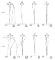
以下、本発明のマクロレンズの実施例1〜3について説明する。ここで、実施例1〜2は参考例である。実施例1〜3の無限遠物点合焦時(a)及び倍率−0.52時(a)でのレンズ断面図をそれぞれ図1〜図3に示す。図中、第1レンズ群はG1、第2レンズ群はG2、第3レンズ群はG3、絞りはS、像面はIで示してある。 Examples 1 to 3 of the macro lens of the present invention will be described below. Here, Examples 1-2 are reference examples. FIGS. 1 to 3 show lens cross-sectional views of Examples 1 to 3 when focusing on an object point at infinity (a) and at a magnification of −0.52 (a), respectively. In the figure, the first lens group is indicated by G1, the second lens group is indicated by G2, the third lens group is indicated by G3, the stop is indicated by S, and the image plane is indicated by I.
本発明の実施例1のマクロレンズを図1に示す。第1レンズ群G1は、物対側から順に、物体側に凹面を向けた負メニスカスレンズの第1レンズ、物体側に凹面を向けた正メニスカスレンズの第2レンズ、両凸正レンズの第3レンズ、物体側に凸面を向けた正メニスカスレンズの第4レンズ、両凹負レンズの第5レンズ、絞り、両凹負レンズの第6レンズ、像面側に凸面を向けた正メニスカスレンズの第7レンズ、両凸正レンズの第8レンズからなり、第2レンズ群は、像面側に凹面を向けた負メニスカスレンズの第9レンズ、像面側に凹面を向けた負メニスカスレンズと両凸正レンズの接合正レンズの第10レンズで構成されている。 FIG. 1 shows a macro lens of Example 1 of the present invention. The first lens group G1 includes, in order from the object side, a first lens of a negative meniscus lens having a concave surface facing the object side, a second lens of a positive meniscus lens having a concave surface facing the object side, and a third lens of a biconvex positive lens. A fourth lens of a positive meniscus lens having a convex surface facing the object side, a fifth lens of a biconcave negative lens, a stop, a sixth lens of a biconcave negative lens, and a positive meniscus lens having a convex surface facing the image surface side. The second lens group consists of a negative meniscus lens with a concave surface facing the image surface, a negative meniscus lens with a concave surface facing the image surface, and a biconvex lens. The positive lens is composed of a tenth lens of a cemented positive lens.
近距離物点へのフォーカシングは、第1レンズ群と第2レンズ群をそれぞれ物対側に移動することによって行う。 Focusing to a short-distance object point is performed by moving the first lens group and the second lens group to the object-pair side.
この実施例の像高IH:11.1mm、像面Iに配置されるCCDの画素は5.5μmピッチである。 In this embodiment, the image height IH is 11.1 mm, and the CCD pixels arranged on the image plane I have a pitch of 5.5 μm.
本発明の実施例2のマクロレンズを図2に示す。第1レンズ群G1は、物対側から順に、物体側に凹面を向けた負メニスカスレンズの第1レンズ、物体側に凹面を向けた正メニスカスレンズの第2レンズ、物体側に凸面を向けた正メニスカスレンズの第3レンズ、物体側に凸面を向けた正メニスカスレンズの第4レンズ、両凹負レンズの第5レンズ、絞り、両凹負レンズの第6レンズ、像面側に凸面を向けた正メニスカスレンズの第7レンズ、両凸正レンズの第8レンズからなり、第2レンズ群は、像面側に凹面を向けた負メニスカスレンズの第9レンズ、像面側に凹面を向けた負メニスカスレンズと両凸正レンズの接合正レンズの第10レンズで構成されている。 FIG. 2 shows a macro lens of Example 2 of the present invention. The first lens group G1, in order from the object side, has a first lens of a negative meniscus lens having a concave surface facing the object side, a second lens of a positive meniscus lens having a concave surface facing the object side, and a convex surface facing the object side. The third lens of the positive meniscus lens, the fourth lens of the positive meniscus lens with the convex surface facing the object side, the fifth lens of the biconcave negative lens, the stop, the sixth lens of the biconcave negative lens, and the convex surface facing the image surface side The seventh lens of the positive meniscus lens and the eighth lens of the biconvex positive lens, the second lens group has the ninth lens of the negative meniscus lens with the concave surface facing the image surface side, and the concave surface facing the image surface side It is composed of a tenth lens which is a cemented positive lens composed of a negative meniscus lens and a biconvex positive lens.
近距離物点へのフォーカシングは、第1レンズ群と第2レンズ群をそれぞれ物対側に移動することによって行う。 Focusing to a short-distance object point is performed by moving the first lens group and the second lens group to the object-pair side.
この実施例の像高IH:11.1mm、像面Iに配置されるCCDの画素は5.5μmピッチである。 In this embodiment, the image height IH is 11.1 mm, and the CCD pixels arranged on the image plane I have a pitch of 5.5 μm.
本発明の実施例3のマクロレンズを図3に示す。第1レンズ群G1は、物対側から順に、物体側に凹面を向けた負メニスカスレンズの第1レンズ、物体側に凹面を向けた正メニスカスレンズの第2レンズ、両凸正レンズの第3レンズ、物体側に凸面を向けた正メニスカスレンズの第4レンズからなり、第2レンズ群は、両凹負レンズの第5レンズ、絞り、両凹負レンズの第6レンズ、像面側に凸面を向けた正メニスカスレンズの第7レンズ、両凸正レンズの第8レンズからなり、第3レンズ群は、像面側に凹面を向けた負メニスカスレンズの第9レンズ、像面側に凹面を向けた負メニスカスレンズと両凸正レンズの接合正レンズの第10レンズで構成されている。 FIG. 3 shows a macro lens of Example 3 of the present invention. The first lens group G1 includes, in order from the object side, a first lens of a negative meniscus lens having a concave surface facing the object side, a second lens of a positive meniscus lens having a concave surface facing the object side, and a third lens of a biconvex positive lens. The lens is composed of a fourth lens of a positive meniscus lens having a convex surface facing the object side. The second lens group includes a fifth lens of a biconcave negative lens, an aperture, a sixth lens of a biconcave negative lens, and a convex surface on the image surface side. The seventh lens of the positive meniscus lens facing the lens and the eighth lens of the biconvex positive lens. The third lens group has a ninth lens of the negative meniscus lens with the concave surface facing the image surface and a concave surface facing the image surface. It is composed of a tenth lens of a cemented positive lens composed of a directed negative meniscus lens and a biconvex positive lens.
近距離物点へのフォーカシングは、第1レンズ群と第2レンズ群と第3レンズ群をそれぞれ物対側に移動することによって行う。 Focusing to a short-distance object point is performed by moving the first lens group, the second lens group, and the third lens group to the object-pair side.
この実施例の像高IH:11.1mm、像面Iに配置されるCCDの画素は5.5μmピッチである。 In this embodiment, the image height IH is 11.1 mm, and the CCD pixels arranged on the image plane I have a pitch of 5.5 μm.
以下に、上記各実施例の数値データを示すが、記号は上記の外、fL は無限遠物点合焦時における全系の焦点距離、FNOはFナンバー、Mは倍率、r1 、r2 …は各レンズ面の曲率半径、d1 、d2 …は各レンズ面間の間隔、nd1、nd2…は各レンズのd線の屈折率、νd1、νd2…は各レンズのアッベ数である。 The numerical data of each of the above embodiments are shown below. Symbols are the above, f L is the focal length of the entire system when focusing on an object point at infinity, F NO is the F number, M is the magnification, r 1 , r 2 ... is the radius of curvature of each lens surface, d 1 , d 2 ... are the distances between the lens surfaces, n d1 , n d2 ... are the refractive indices of the d-line of each lens, and ν d1 , ν d2 . Abbe number.
(実施例1)
r1 = -35.629 d1 = 2.00 nd1 =1.64769 νd1 =33.79
r2 = -74.905 d2 = 0.94
r3 = -702.420 d3 = 4.03 nd2 =1.77250 νd2 =49.60
r4 = -49.343 d4 = 0.10
r5 = 45.810 d5 = 5.06 nd3 =1.72916 νd3 =54.68
r6 =-809755.657 d6 = 0.10
r7 = 26.150 d7 = 2.80 nd4 =1.52249 νd4 =59.84
r8 = 32.770 d8 = 5.55
r9 = -311.668 d9 = 1.41 nd5 =1.59551 νd5 =39.24
r10= 21.286 d10= 3.13
r11= ∞(絞り) d11= 3.08
r12= -21.101 d12= 1.35 nd6 =1.58144 νd6 =40.75
r13= 93.106 d13= 1.30
r14= -323.070 d14= 4.50 nd7 =1.49700 νd7 =81.54
r15= -30.291 d15= 0.30
r16= 56.785 d16= 4.54 nd8 =1.77250 νd8 =49.60
r17= -56.785 d17= (可変)
r18= 5517.326 d18= 1.52 nd9 =1.51742 νd9 =52.43
r19= 38.046 d19= 1.93
r20= 91.845 d20= 1.55 nd10=1.76182 νd10=26.52
r21= 40.260 d21= 4.87 nd11=1.74100 νd11=52.64
r22= -60.775 d22= (可変)
r23= ∞(像面)
fL 51.000
FNO 1.83
M -1/∞ -0.1 -0.52
d17 0.50 2.08 8.02
d22 35.18 39.37 58.83 。
Example 1
r 1 = -35.629 d 1 = 2.00 n d1 = 1.64769 ν d1 = 33.79
r 2 = -74.905 d 2 = 0.94
r 3 = -702.420 d 3 = 4.03 n d2 = 1.77250 ν d2 = 49.60
r 4 = -49.343 d 4 = 0.10
r 5 = 45.810 d 5 = 5.06 n d3 = 1.72916 ν d3 = 54.68
r 6 = -809755.657 d 6 = 0.10
r 7 = 26.150 d 7 = 2.80 n d4 = 1.52249 ν d4 = 59.84
r 8 = 32.770 d 8 = 5.55
r 9 = -311.668 d 9 = 1.41 n d5 = 1.59551 ν d5 = 39.24
r 10 = 21.286 d 10 = 3.13
r 11 = ∞ (aperture) d 11 = 3.08
r 12 = -21.101 d 12 = 1.35 n d6 = 1.58144 ν d6 = 40.75
r 13 = 93.106 d 13 = 1.30
r 14 = -323.070 d 14 = 4.50 n d7 = 1.49700 ν d7 = 81.54
r 15 = -30.291 d 15 = 0.30
r 16 = 56.785 d 16 = 4.54 n d8 = 1.77250 ν d8 = 49.60
r 17 = -56.785 d 17 = (variable)
r 18 = 5517.326 d 18 = 1.52 n d9 = 1.51742 ν d9 = 52.43
r 19 = 38.046 d 19 = 1.93
r 20 = 91.845 d 20 = 1.55 n d10 = 1.76182 ν d10 = 26.52
r 21 = 40.260 d 21 = 4.87 n d11 = 1.74100 ν d11 = 52.64
r 22 = -60.775 d 22 = (variable)
r 23 = ∞ (image plane)
f L 51.000
F NO 1.83
M -1 / ∞ -0.1 -0.52
d 17 0.50 2.08 8.02
d 22 35.18 39.37 58.83.
(実施例2)
r1 = -35.941 d1 = 2.00 nd1 =1.64769 νd1 =33.79
r2 = -70.445 d2 = 1.40
r3 = -910.133 d3 = 3.99 nd2 =1.77250 νd2 =49.60
r4 = -51.742 d4 = 0.10
r5 = 43.701 d5 = 4.34 nd3 =1.72916 νd3 =54.68
r6 =3929264.108 d6 = 0.10
r7 = 24.021 d7 = 2.80 nd4 =1.52249 νd4 =59.84
r8 = 28.431 d8 = 5.16
r9 = -861.896 d9 = 1.30 nd5 =1.59551 νd5 =39.24
r10= 19.550 d10= 3.31
r11= ∞(絞り) d11= 5.78
r12= -20.465 d12= 1.35 nd6 =1.58144 νd6 =40.75
r13= 99.536 d13= 0.91
r14= -257.770 d14= 4.50 nd7 =1.49700 νd7 =81.54
r15= -28.944 d15= 0.30
r16= 53.287 d16= 6.17 nd8 =1.77250 νd8 =49.60
r17= -59.475 d17= (可変)
r18=-17636653.385 d18= 1.38 nd9 =1.51742 νd9 =52.43
r19= 36.329 d19= 1.73
r20= 96.180 d20= 1.68 nd10=1.76182 νd10=26.52
r21= 40.845 d21= 4.86 nd11=1.74100 νd11=52.64
r22= -53.026 d22= (可変)
r23= ∞(像面)
fL 51.009
FNO 1.83
M -1/∞ -0.1 -0.52
d17 0.50 1.71 6.79
d22 35.06 39.46 58.75 。
(Example 2)
r 1 = -35.941 d 1 = 2.00 n d1 = 1.64769 ν d1 = 33.79
r 2 = -70.445 d 2 = 1.40
r 3 = -910.133 d 3 = 3.99 n d2 = 1.77250 ν d2 = 49.60
r 4 = -51.742 d 4 = 0.10
r 5 = 43.701 d 5 = 4.34 n d3 = 1.72916 ν d3 = 54.68
r 6 = 3929264.108 d 6 = 0.10
r 7 = 24.021 d 7 = 2.80 n d4 = 1.52249 ν d4 = 59.84
r 8 = 28.431 d 8 = 5.16
r 9 = -861.896 d 9 = 1.30 n d5 = 1.59551 ν d5 = 39.24
r 10 = 19.550 d 10 = 3.31
r 11 = ∞ (aperture) d 11 = 5.78
r 12 = -20.465 d 12 = 1.35 n d6 = 1.58144 ν d6 = 40.75
r 13 = 99.536 d 13 = 0.91
r 14 = -257.770 d 14 = 4.50 n d7 = 1.49700 ν d7 = 81.54
r 15 = -28.944 d 15 = 0.30
r 16 = 53.287 d 16 = 6.17 n d8 = 1.77250 ν d8 = 49.60
r 17 = -59.475 d 17 = (variable)
r 18 = -17636653.385 d 18 = 1.38 n d9 = 1.51742 ν d9 = 52.43
r 19 = 36.329 d 19 = 1.73
r 20 = 96.180 d 20 = 1.68 n d10 = 1.76182 ν d10 = 26.52
r 21 = 40.845 d 21 = 4.86 n d11 = 1.74100 ν d11 = 52.64
r 22 = -53.026 d 22 = (variable)
r 23 = ∞ (image plane)
f L 51.009
F NO 1.83
M -1 / ∞ -0.1 -0.52
d 17 0.50 1.71 6.79
d 22 35.06 39.46 58.75.
(実施例3)
r1 = -37.956 d1 = 1.52 nd1 =1.64769 νd1 =33.79
r2 = -83.532 d2 = 1.00
r3 = -534.319 d3 = 4.08 nd2 =1.77250 νd2 =49.60
r4 = -51.466 d4 = 0.10
r5 = 42.553 d5 = 5.08 nd3 =1.72916 νd3 =54.68
r6 =-171439725.185 d6 = 0.10
r7 = 25.634 d7 = 2.80 nd4 =1.52249 νd4 =59.84
r8 = 31.696 d8 = (可変)
r9 = -296.224 d9 = 1.30 nd5 =1.59551 νd5 =39.24
r10= 20.553 d10= 3.13
r11= ∞(絞り) d11= 3.08
r12= -21.557 d12= 1.35 nd6 =1.58144 νd6 =40.75
r13= 102.583 d13= 1.21
r14= -308.613 d14= 4.50 nd7 =1.49700 νd7 =81.54
r15= -30.433 d15= 0.30
r16= 53.387 d16= 4.51 nd8 =1.77250 νd8 =49.60
r17= -61.253 d17= (可変)
r18=116624.465 d18= 1.38 nd9 =1.51742 νd9 =52.43
r19= 36.250 d19= 1.94
r20= 83.298 d20= 1.20 nd10=1.76182 νd10=26.52
r21= 38.827 d21= 4.19 nd11=1.74100 νd11=52.64
r22= -61.075 d22= (可変)
r23= ∞(像面)
fL 51.000
FNO 1.83
M -1/∞ -0.1 -0.52
d8 5.57 5.55 5.18
d17 0.50 2.09 8.17
d22 35.19 39.41 59.67 。
(Example 3)
r 1 = -37.956 d 1 = 1.52 n d1 = 1.64769 ν d1 = 33.79
r 2 = -83.532 d 2 = 1.00
r 3 = -534.319 d 3 = 4.08 n d2 = 1.77250 ν d2 = 49.60
r 4 = -51.466 d 4 = 0.10
r 5 = 42.553 d 5 = 5.08 n d3 = 1.72916 ν d3 = 54.68
r 6 = -171439725.185 d 6 = 0.10
r 7 = 25.634 d 7 = 2.80 n d4 = 1.52249 ν d4 = 59.84
r 8 = 31.696 d 8 = (variable)
r 9 = -296.224 d 9 = 1.30 n d5 = 1.59551 ν d5 = 39.24
r 10 = 20.553 d 10 = 3.13
r 11 = ∞ (aperture) d 11 = 3.08
r 12 = -21.557 d 12 = 1.35 n d6 = 1.58144 ν d6 = 40.75
r 13 = 102.583 d 13 = 1.21
r 14 = -308.613 d 14 = 4.50 n d7 = 1.49700 ν d7 = 81.54
r 15 = -30.433 d 15 = 0.30
r 16 = 53.387 d 16 = 4.51 n d8 = 1.77250 ν d8 = 49.60
r 17 = -61.253 d 17 = (variable)
r 18 = 116624.465 d 18 = 1.38 n d9 = 1.51742 ν d9 = 52.43
r 19 = 36.250 d 19 = 1.94
r 20 = 83.298 d 20 = 1.20 n d10 = 1.76182 ν d10 = 26.52
r 21 = 38.827 d 21 = 4.19 n d11 = 1.74100 ν d11 = 52.64
r 22 = -61.075 d 22 = (variable)
r 23 = ∞ (image plane)
f L 51.000
F NO 1.83
M -1 / ∞ -0.1 -0.52
d 8 5.57 5.55 5.18
d 17 0.50 2.09 8.17
d 22 35.19 39.41 59.67.
上記実施例1〜3の無限遠にフォーカシングした場合(a)と倍率−0.52にフォーカシングした場合(b)の収差図をそれぞれ図4〜図6に示す。これら収差図において、“SA”は球面収差、“AS”は非点収差、“DT”は歪曲収差、“CC”は倍率色収差を示す。また、各収差図中、“IH”は像高を示す。 次に、上記各実施例における条件(1)〜(11)の値を示す。ただし、条件(3)、(4)はそれぞれ条件(3−1)又は(3−2)、(4−1)又は(4−2)を意味する。
実施例 1 2 3
(1) -2.10 -2.27 -2.13
(2) -2.81 -3.08 -2.63
(3) 1.26 1.30 0.70
(4) 2.71 2.45 2.71
(5) -0.52 -0.52 -0.52
(6) 13.3 13.3 13.3
(7) 1.83 1.83 1.83
(8) 0.61 0.59 0.62
(9) 11.1 11.1 11.1
(10) 3.15 3.15 3.16
(11) 9.45 7.97 9.68 。
FIGS. 4 to 6 show aberration diagrams when focusing on infinity in Examples 1 to 3 (a) and focusing to -0.52 (b), respectively. In these aberration diagrams, “SA” indicates spherical aberration, “AS” indicates astigmatism, “DT” indicates distortion, and “CC” indicates lateral chromatic aberration. In each aberration diagram, “IH” indicates the image height. Next, the values of the conditions (1) to (11) in the above embodiments will be shown. However, conditions (3) and (4) mean conditions (3-1) or (3-2), (4-1) or (4-2), respectively.
Example 1 2 3
(1) -2.10 -2.27 -2.13
(2) -2.81 -3.08 -2.63
(3) 1.26 1.30 0.70
(4) 2.71 2.45 2.71
(5) -0.52 -0.52 -0.52
(6) 13.3 13.3 13.3
(7) 1.83 1.83 1.83
(8) 0.61 0.59 0.62
(9) 11.1 11.1 11.1
(10) 3.15 3.15 3.16
(11) 9.45 7.97 9.68.
以上に説明した本発明のマクロレンズは、前記したように、銀塩又はデジタル一眼レフレックスカメラに適用可能のものである。これらを以下に例示する。 As described above, the macro lens of the present invention described above can be applied to a silver salt or digital single lens reflex camera. These are exemplified below.
図7に、本発明のマクロレンズを撮影レンズとして用いる銀塩タイプの一眼レフレックスカメラを示す。この図7において、10は一眼レフレックスカメラで、2は撮影レンズ、4は撮影レンズ2を一眼レフレックスカメラ10に着脱可能とするマウント部であり、スクリュータイプのマウントやバヨネットタイプのマウント(図の場合は、バヨネットタイプのマウントを用いている。)等が用いられる。また、6はフィルム、11は撮影レンズ2の光路3上レンズ系2とフィルム6との間に配置されたクイックリターンミラー、12はクイックリターンミラーより反射された光路に配置されたファインダースクリーン、13はペンタプリズム、14はファインダー、Eは観察者の眼(アイポイント)である。このような構成の一眼レフレックスカメラ10の撮影レンズ2として本発明のマクロレンズが用いられている。
FIG. 7 shows a silver salt type single-lens reflex camera using the macro lens of the present invention as a photographing lens. In FIG. 7,
次に、図8(a)に、本発明のマクロレンズをデジタルタイプの一眼レフカメラの対物光学系に組み込んだ構成の概念図を示す。この例の場合、対物光学系21としては、実施例1のマクロレンズを用いて示す。この対物光学系21を通った結像光束は、バックフォーカス側に配置されたハーフミラープリズム(ビームスプリッター等)22を介して、撮影用光路とファインダー用光路とに分離される。なお、ハーフミラープリズム22に代えてクイックリターンミラーを用いれば、光量の損失を防止でき望ましい。さらに、撮影用光路中には、ローパスフィルターや赤外カットフィルター等のフィルターFとCCD23が配され、物体像がこのフィルターFを通ってCCD23の撮像面上に形成される。また、ファインダー用光路には、その撮像面と共役な位置に形成される1次像面上にスクリーンマット24が配され、この1次像が平面ミラー25で反射され、リレー光学系26により2次像としてリレーされると共に、正立正像にされている。そして、この2次像を接眼レンズ27によって観察像眼球Eに導く。
Next, FIG. 8A shows a conceptual diagram of a configuration in which the macro lens of the present invention is incorporated in an objective optical system of a digital single-lens reflex camera. In this example, the objective
また、この図8(a)のファインダー光路部分は、図8(b)に示すように、平面ミラー25とリレー光学系26とを正パワーを持った凹面鏡プリズム28に置き換えてもよい。このような構成とすれば、部品点数を減らすことができると共に、コンパクト化も実現できる。なお、この凹面鏡プリズム28は、入射面と射出面にもパワーを持たせてもよいし、反射面は回転対称面(球面や非球面等)の他、アナモルフィック面や自由曲面等の非回転対称面であってもよい。また、CCD23に代えて、銀塩フィルムを配置した銀塩カメラとして構成してもよい。 In the viewfinder optical path portion of FIG. 8A, the plane mirror 25 and the relay optical system 26 may be replaced with a concave mirror prism 28 having a positive power, as shown in FIG. 8B. With such a configuration, the number of parts can be reduced and downsizing can be realized. The concave mirror prism 28 may have power on the entrance surface and the exit surface, and the reflection surface may be a rotationally symmetric surface (spherical surface, aspheric surface, etc.), non-anamorphic surface, free curved surface, etc. It may be a rotationally symmetric surface. Moreover, it may replace with CCD23 and may be comprised as a silver salt camera which has arrange | positioned the silver salt film.
以上の本発明のマクロレンズ及びそれを備えたカメラは例えば次のように構成することができる。 The above-described macro lens of the present invention and a camera including the macro lens can be configured as follows, for example.
〔1〕 物体側より順に、正パワーの第1レンズ群、正パワーの第2レンズ群よりなり、前記第1レンズ群は、物体側が凹面の負メニスカスレンズを最も物体側に配置し、無限遠物点合焦時から最至近物点へのフォーカシング時に、前記第1レンズ群と前記第2レンズ群との間隔を変化させそれぞれ独立に物体側へ移動させることを特徴とするマクロレンズ。 [1] In order from the object side, a first lens unit having a positive power and a second lens group having a positive power are arranged. The first lens unit has a negative meniscus lens having a concave surface on the object side closest to the object side. A macro lens, wherein the distance between the first lens group and the second lens group is changed and moved independently toward the object side during focusing from the object point in-focus to the closest object point.
〔2〕 前記第1レンズ群中に絞りを配置したことを特徴とする請求項1記載のマクロレンズ。 [2] The macro lens according to [1], wherein a diaphragm is disposed in the first lens group.
〔3〕 前記負メニスカスレンズと前記絞りとの間に複数の正レンズを含むことを特徴とする請求項2記載のマクロレンズ。 [3] The macro lens according to claim 2, comprising a plurality of positive lenses between the negative meniscus lens and the stop.
〔4〕 前記絞りの直前及び直後のレンズを負レンズとしたことを特徴とする請求項2又は3記載のマクロレンズ。 [4] The macro lens according to claim 2 or 3, wherein the lens immediately before and after the stop is a negative lens.
〔5〕 前記正の第1レンズ群が、物体側から順に、前記物体側が凹面の負メニスカスレンズ、正レンズ群、像側面よりも物体側面が曲率半径の絶対値の小さい面の正レンズ、物体側面よりも像側面が曲率半径の絶対値の小さい面の負レンズ、絞り、像側面よりも物体側面が曲率半径の絶対値の小さい面の負レンズ、物体側面よりも像側面が曲率半径の絶対値の小さい面の正レンズ、を有することを特徴とする請求項1記載のマクロレンズ。
[5] The positive first lens group includes, in order from the object side, a negative meniscus lens having a concave surface on the object side, a positive lens group, a positive lens having an object side surface with a smaller radius of curvature than the image side surface, and an object A negative lens with a surface having a smaller radius of curvature than the side surface, an aperture, a negative lens having a surface with a smaller radius of curvature than the image side, an image surface having an absolute radius of curvature than the object side The macro lens according to
〔6〕 前記第2レンズ群が、正レンズと負レンズとを接合させた接合正レンズを有することを特徴とする請求項1から5の何れか1項記載のマクロレンズ。
[6] The macro lens according to any one of
〔7〕 物体側より順に、正パワーの第1レンズ群、負パワーの第2レンズ群、正パワーの第3レンズ群よりなり、前記第1レンズ群は、物体側が凹面の負メニスカスレンズを最も物体側に配置し、無限遠物点合焦時から最至近物点へのフォーカシング時に、各レンズ群の間隔を変化させそれぞれ独立に物体側へ移動させることを特徴とするマクロレンズ。 [7] In order from the object side, a first lens unit having a positive power, a second lens group having a negative power, and a third lens group having a positive power. The first lens group has a negative meniscus lens having a concave surface on the object side most. A macro lens that is arranged on the object side and moves to the object side independently by changing the interval of each lens group during focusing from the object point at infinity to the closest object point.
〔8〕 前記第2レンズ群中に絞りを配置したことを特徴とする請求項7記載のマクロレンズ。 [8] The macro lens according to [7], wherein a stop is disposed in the second lens group.
〔9〕 前記第1レンズ群が、前記負メニスカスレンズの像側に複数の正レンズを含んでなることを特徴とする請求項8記載のマクロレンズ。 [9] The macro lens according to claim 8, wherein the first lens group includes a plurality of positive lenses on the image side of the negative meniscus lens.
〔10〕 前記絞りの直前及び直後のレンズを負レンズとしたことを特徴とする請求項8又は9記載のマクロレンズ。
[10] The macro lens according to
〔11〕 前記正の第1レンズ群及び前記負の第2レンズ群の合成レンズ系が、物体側から順に、前記物体側が凹面の負メニスカスレンズ、正レンズ群、像側面よりも物体側面が曲率半径の絶対値の小さい面の正レンズ、物体側面よりも像側面が曲率半径の絶対値の小さい面の負レンズ、絞り、像側面よりも物体側面が曲率半径の絶対値の小さい面の負レンズ、物体側面よりも像側面が曲率半径の絶対値の小さい面の正レンズ、を有することを特徴とする請求項7又は8記載のマクロレンズ。
[11] In the composite lens system of the positive first lens group and the negative second lens group, in order from the object side, a negative meniscus lens having a concave surface on the object side, a positive lens group, and an object side surface having a curvature more than the image side surface A positive lens with a surface with a small radius of curvature, a negative lens with a surface with a smaller radius of curvature than the object side, and a negative lens with a diaphragm, a surface with a smaller radius of curvature on the object side than the
〔12〕 前記第3レンズ群が、正レンズと負レンズとを接合させた接合正レンズを有することを特徴とする請求項7から11の何れか1項記載のマクロレンズ。 [12] The macro lens according to any one of claims 7 to 11, wherein the third lens group includes a cemented positive lens in which a positive lens and a negative lens are cemented.
〔13〕 以下の条件(3−1)、(4−1)を満足することを特徴とする請求項1から6の何れか1項記載のマクロレンズ。
[13] The macro lens according to any one of
0.5<f1 /fL <1.8 ・・・(3−1)
1.8<f2 /fL <3.5 ・・・(4−1)
ただし、f1 は第1レンズ群の焦点距離、f2 は第2レンズ群の焦点距離、fL は無限遠物点合焦時における全系の焦点距離である。
0.5 <f 1 / f L <1.8 (3-1)
1.8 <f 2 / f L <3.5 (4-1)
Here, f 1 is the focal length of the first lens group, f 2 is the focal length of the second lens group, and f L is the focal length of the entire system when focusing on an object point at infinity.
〔14〕 以下の条件(3−2)、(4−2)を満足することを特徴とする請求項7から12の何れか1項記載のマクロレンズ。 [14] The macro lens as set forth in any one of [7] to [12], wherein the following conditions (3-2) and (4-2) are satisfied.
0.5<f1 /fL <1.8 ・・・(3−2)
1.8<f3 /fL <3.5 ・・・(4−2)
ただし、f1 は第1レンズ群の焦点距離、f3 は第3レンズ群の焦点距離、fL は無限遠物点合焦時における全系の焦点距離である。
0.5 <f 1 / f L <1.8 (3-2)
1.8 <f 3 / f L <3.5 (4-2)
Here, f 1 is the focal length of the first lens group, f 3 is the focal length of the third lens group, and f L is the focal length of the entire system when focusing on an object point at infinity.
〔15〕 以下の条件(1)を満足することを特徴とする請求項1から14の何れか1項記載のマクロレンズ。
[15] The macro lens according to any one of
−4<fF /fL <−1 ・・・(1)
ただし、fF は最も物体側の負メニスカスレンズの焦点距離、fL は無限遠物点合焦時における全系の焦点距離である。
-4 <f F / f L <-1 (1)
Here, f F is the focal length of the negative meniscus lens closest to the object side, and f L is the focal length of the entire system when focusing on an object point at infinity.
〔16〕 以下の条件(2)を満足することを特徴とする請求項1から15の何れか1項記載のマクロレンズ。 [16] The macro lens according to any one of [1] to [15], wherein the following condition (2) is satisfied.
−12.5<(r1 +r2 )/(r1 −r2 )<−0.85・・・(2)
ただし、r1 は最も物体側の負メニスカスレンズの物体側面曲率半径、r2 は最も物体側の負メニスカスレンズの像側面曲率半径である。
−12.5 <(r 1 + r 2 ) / (r 1 −r 2 ) <− 0.85 (2)
Here, r 1 is the radius of curvature of the object side surface of the negative meniscus lens closest to the object side, and r 2 is the radius of curvature of the image side surface of the negative meniscus lens closest to the object side.
〔17〕 最至近物点合焦時に以下の条件(5)を満足することを特徴とする請求項1から16の何れか1項記載のマクロレンズ。 [17] The macro lens according to any one of [1] to [16], wherein the following condition (5) is satisfied at the time of focusing on the closest object point.
−1.0<MG<−0.4 ・・・(5)
ただし、MGは最大撮影倍率である。
-1.0 <MG <-0.4 (5)
However, MG is the maximum photographing magnification.
〔18〕 以下の条件(7)を満足することを特徴とする請求項1から17の何れか1項記載のマクロレンズ。
[18] The macro lens according to any one of
1.0<F<3.0 ・・・(7)
ただし、Fは無限遠物点合焦時かつ絞り開放時のFナンバーである。
1.0 <F <3.0 (7)
However, F is an F number at the time of focusing on an object point at infinity and when the aperture is opened.
〔19〕 以下の条件(8)を満足することを特徴とする請求項1から18の何れか1項記載のマクロレンズ。 [19] The macro lens according to any one of [1] to [18], wherein the following condition (8) is satisfied.
0.4<Δd1 /fL <0.8 ・・・(8)
ただし、Δd1 は無限遠物点合焦時から最至近物点合焦時における第1レンズ群の繰り出し量、fL は無限遠物点合焦時における全系の焦点距離である。
0.4 <Δd 1 / f L <0.8 (8)
However, Δd 1 is the amount of extension of the first lens group from the time of focusing on an object point at infinity to the time of focusing on the closest object point, and f L is the focal length of the entire system when focusing on an object point at infinity.
〔20〕 請求項1から19の何れか1項記載のズームレンズと、その像側に配された撮像範囲を制限する機構とを設けたことを特徴とするカメラ。 [20] A camera comprising: the zoom lens according to any one of [1] to [19]; and a mechanism for limiting an imaging range arranged on an image side thereof.
〔21〕 以下の条件(6)を満足することを特徴とする請求項20記載のカメラ。 [21] The camera according to [20], wherein the following condition (6) is satisfied.
7°<SW<16° ・・・(6)
ただし、SWは無限遠合焦時におけるカメラ本体の撮像範囲における最大像高に入射する対角光線の入射半画角であり、撮像面の撮像範囲が任意に変更可能な場合はその取り得る範囲の最大値である。
7 ° <SW <16 ° (6)
However, SW is an incident half field angle of a diagonal ray incident on the maximum image height in the imaging range of the camera body at the time of focusing on infinity, and the range that can be taken when the imaging range of the imaging surface can be arbitrarily changed Is the maximum value.
〔22〕 前記撮像範囲を制限する機構が矩形の開口からなる視野絞りであることを特徴とする請求項20又は21記載のカメラ。 [22] The camera according to claim 20 or 21, wherein the mechanism for limiting the imaging range is a field stop including a rectangular opening.
〔23〕 前記撮像範囲を制限する機構が矩形の撮像領域を持つ電子撮像素子であることを特徴とする請求項20又は21記載のカメラ。 [23] The camera according to claim 20 or 21, wherein the mechanism for limiting the imaging range is an electronic imaging device having a rectangular imaging area.
〔24〕 以下の条件(6)を満足するように形成されたカメラ本体と着脱可能とするマウント部を備えたことを特徴とする請求項1から19の何れか1項記載のマクロレンズ。 [24] The macro lens according to any one of [1] to [19], further comprising a camera body formed so as to satisfy the following condition (6) and a mount portion that is detachable.
7°<SW<16° ・・・(6)
ただし、SWは無限遠合焦時におけるカメラ本体の撮像範囲における最大像高に入射する対角光線の入射半画角であり、撮像面の撮像範囲が任意に変更可能な場合はその取り得る範囲の最大値である。
7 ° <SW <16 ° (6)
However, SW is an incident half field angle of a diagonal ray incident on the maximum image height in the imaging range of the camera body at the time of focusing on infinity, and the range that can be taken when the imaging range of the imaging surface can be arbitrarily changed Is the maximum value.
〔25〕 以下の条件(9)、(10)を満足することを特徴とする請求項1乃至19何れか1項記載のマクロレンズ。 [25] The macro lens according to any one of [1] to [19], wherein the following conditions (9) and (10) are satisfied.
13mm>IH>10mm ・・・(9)
3.5>fb /IH ・・・(10)
ただし、IHは無限遠物点合焦時におけるイメージサークル半径、fb は無限遠物点合焦時におけるレンズ系のバックフォーカスである。
13 mm>IH> 10 mm (9)
3.5> f b / IH (10)
Here, IH is the image circle radius when focusing on an object point at infinity, and f b is the back focus of the lens system when focusing on an object point at infinity.
〔26〕 以下の条件(11)を満足することを特徴とする請求項23記載のカメラ。
[26] The camera according to
1°<|EW|<11° ・・・(11)
ただし、EWは無限遠物点合焦時におけるカメラ本体の撮像面における最大像高に入射する対角主光線の射出光線と光軸とのなす角であり、撮像面の撮像範囲が任意に変更可能な場合はその取る得る範囲の像高最大位置における値である。
1 ° <| EW | <11 ° (11)
However, EW is the angle formed by the light beam emitted from the diagonal principal ray incident on the maximum image height on the imaging surface of the camera body when focusing on an object point at infinity, and the imaging range on the imaging surface can be changed arbitrarily. If possible, it is the value at the maximum image height within the possible range.
以上の説明から明らかなように、本発明によると、Fナンバー1.8と大口径で、無限から近距離まで諸収差が良好に補正されたマクロレンズを提供することができる。 As is apparent from the above description, according to the present invention, it is possible to provide a macro lens having an F number of 1.8 and a large aperture, and various aberrations corrected favorably from infinity to a short distance.
G1…第1レンズ群
G2…第2レンズ群
G3…第3レンズ群
S…絞り
I…像面
E…観察者眼球(アイポイント)
F…光学フィルター等の部材
2…撮影レンズ
3…光路
4…マウント部
6…フィルム
10…一眼レフレックスカメラ
11…クイックリターンミラー
12…ファインダースクリーン
13…ペンタプリズム
14…ファインダー
21…対物光学系
22…ハーフミラープリズム
23…CCD
24…スクリーンマット
25…平面ミラー75
26…リレー光学系
27…接眼レンズ
28…凹面鏡プリズム
G1 ... first lens group G2 ... second lens group G3 ... third lens group S ... stop I ... image plane E ... observer eyeball (eye point)
F ... member 2 such as optical filter ... photographing lens 3 ... optical path 4 ... mount portion 6 ...
24 ... Screen mat 25 ... Flat mirror 75
26 ... Relay optical system 27 ... Eyepiece 28 ... Concave mirror prism
Claims (16)
0.5<f1 /fL <1.8 ・・・(3−2)
1.8<f3 /fL <3.5 ・・・(4−2)
−12.5<(r1 +r2 )/(r1 −r2 )<−0.85・・・(2)
0.4<Δd1 /fL <0.8 ・・・(8)
ただし、f1 は第1レンズ群の焦点距離、f3 は第3レンズ群の焦点距離、fL は無限遠物点合焦時における全系の焦点距離、r1 は最も物体側の負メニスカスレンズの物体側面曲率半径、r2 は最も物体側の負メニスカスレンズの像側面曲率半径、Δd1 は無限遠物点合焦時から最至近物点合焦時における第1レンズ群の繰り出し量である。 In order from the object side, a first lens group having positive power, a second lens unit having a negative power, a third lens group of positive power, said first lens group, the most object side negative meniscus lens the object-side concave surface of the At the time of focusing from the object point at infinity to the closest object point, the distance between the lens groups is changed and moved to the object side independently, and the following conditions (3-2), (4-2) ), (2), and (8).
0.5 <f 1 / f L <1.8 (3-2)
1.8 <f 3 / f L <3.5 (4-2)
−12.5 <(r 1 + r 2 ) / (r 1 −r 2 ) <− 0.85 (2)
0.4 <Δd 1 / f L <0.8 (8)
Where f 1 is the focal length of the first lens unit, f 3 is the focal length of the third lens unit, f L is the focal length of the entire system when focusing on an object point at infinity, and r 1 is the negative meniscus on the most object side. The object side radius of curvature of the lens, r 2 is the radius of curvature of the image side of the negative meniscus lens closest to the object side, and Δd 1 is the amount of extension of the first lens unit when focusing on the object point at infinity to focusing on the closest object point. is there.
−4<fF /fL <−1 ・・・(1)
ただし、fF は最も物体側の負メニスカスレンズの焦点距離、fL は無限遠物点合焦時における全系の焦点距離である。 The macro lens according to any one of claims 1 to 6, wherein the following condition (1) is satisfied.
-4 <f F / f L <-1 (1)
Here, f F is the focal length of the negative meniscus lens closest to the object side, and f L is the focal length of the entire system when focusing on an object point at infinity.
−1.0<MG<−0.4 ・・・(5)
ただし、MGは最大撮影倍率である。 The macro lens according to claim 1, wherein the following condition (5) is satisfied when the closest object point is focused.
-1.0 <MG <-0.4 (5)
However, MG is the maximum photographing magnification.
1.0<F<3.0 ・・・(7)
ただし、Fは無限遠物点合焦時かつ絞り開放時のFナンバーである。 The macro lens according to any one of claims 1 to 8, wherein the following condition (7) is satisfied.
1.0 <F <3.0 (7)
However, F is an F number at the time of focusing on an object point at infinity and when the aperture is opened.
7°<SW<16° ・・・(6)
ただし、SWは無限遠合焦時におけるカメラ本体の撮像範囲における最大像高に入射する対角光線の入射半画角であり、撮像面の撮像範囲が任意に変更可能な場合はその取り得る範囲の最大値である。 The camera according to claim 10, wherein the following condition (6) is satisfied.
7 ° <SW <16 ° (6)
However, SW is an incident half field angle of a diagonal ray incident on the maximum image height in the imaging range of the camera body at the time of focusing on infinity, and the range that can be taken when the imaging range of the imaging surface can be arbitrarily changed Is the maximum value.
7°<SW<16° ・・・(6)
ただし、SWは無限遠合焦時におけるカメラ本体の撮像範囲における最大像高に入射する対角光線の入射半画角であり、撮像面の撮像範囲が任意に変更可能な場合はその取り得る範囲の最大値である。 10. The macro lens according to claim 1, further comprising: a camera body formed so as to satisfy the following condition (6);
7 ° <SW <16 ° (6)
However, SW is an incident half field angle of a diagonal ray incident on the maximum image height in the imaging range of the camera body at the time of focusing on infinity, and the range that can be taken when the imaging range of the imaging surface can be arbitrarily changed Is the maximum value.
13mm>IH>10mm ・・・(9)
3.5>fb /IH ・・・(10)
ただし、IHは無限遠物点合焦時におけるイメージサークル半径、fb は無限遠物点合焦時におけるレンズ系のバックフォーカスである。 The macro lens according to claim 1, wherein the following conditions (9) and (10) are satisfied.
13 mm>IH> 10 mm (9)
3.5> f b / IH (10)
Here, IH is the image circle radius when focusing on an object point at infinity, and f b is the back focus of the lens system when focusing on an object point at infinity.
1°<|EW|<11° ・・・(11)
ただし、EWは無限遠物点合焦時におけるカメラ本体の撮像面における最大像高に入射する対角主光線の射出光線と光軸とのなす角であり、撮像面の撮像範囲が任意に変更可能な場合はその取る得る範囲の像高最大位置における値である。 The camera according to claim 13, wherein the following condition (11) is satisfied.
1 ° <| EW | <11 ° (11)
However, EW is the angle formed by the light beam emitted from the diagonal principal ray incident on the maximum image height on the imaging surface of the camera body when focusing on an object point at infinity, and the imaging range on the imaging surface can be changed arbitrarily. If possible, it is the value at the maximum image height within the possible range.
Priority Applications (1)
| Application Number | Priority Date | Filing Date | Title |
|---|---|---|---|
| JP2008028731A JP4509192B2 (en) | 2008-02-08 | 2008-02-08 | Macro lens and camera equipped with the same |
Applications Claiming Priority (1)
| Application Number | Priority Date | Filing Date | Title |
|---|---|---|---|
| JP2008028731A JP4509192B2 (en) | 2008-02-08 | 2008-02-08 | Macro lens and camera equipped with the same |
Related Parent Applications (1)
| Application Number | Title | Priority Date | Filing Date |
|---|---|---|---|
| JP2001361096A Division JP4156828B2 (en) | 2001-11-27 | 2001-11-27 | Macro lens and camera equipped with the same |
Publications (2)
| Publication Number | Publication Date |
|---|---|
| JP2008191672A JP2008191672A (en) | 2008-08-21 |
| JP4509192B2 true JP4509192B2 (en) | 2010-07-21 |
Family
ID=39751766
Family Applications (1)
| Application Number | Title | Priority Date | Filing Date |
|---|---|---|---|
| JP2008028731A Expired - Fee Related JP4509192B2 (en) | 2008-02-08 | 2008-02-08 | Macro lens and camera equipped with the same |
Country Status (1)
| Country | Link |
|---|---|
| JP (1) | JP4509192B2 (en) |
Families Citing this family (4)
| Publication number | Priority date | Publication date | Assignee | Title |
|---|---|---|---|---|
| KR101676787B1 (en) * | 2010-09-27 | 2016-11-17 | 삼성전자주식회사 | Macro lens system and pickup device having the same |
| WO2012086263A1 (en) * | 2010-12-22 | 2012-06-28 | コニカミノルタオプト株式会社 | Image pickup lens |
| JP2015004717A (en) | 2013-06-19 | 2015-01-08 | リコーイメージング株式会社 | Single focus lens system |
| CN110351405A (en) * | 2019-07-03 | 2019-10-18 | 肯维捷斯(武汉)科技有限公司 | A kind of mobile communication equipment with microcosmic imaging function |
Citations (4)
| Publication number | Priority date | Publication date | Assignee | Title |
|---|---|---|---|---|
| JPH07181390A (en) * | 1993-12-22 | 1995-07-21 | Minolta Co Ltd | Compact macro-lens |
| JPH0815609A (en) * | 1994-06-29 | 1996-01-19 | Olympus Optical Co Ltd | Macro lens |
| JPH08248310A (en) * | 1995-03-13 | 1996-09-27 | Minolta Co Ltd | Variable aberration lens |
| JPH10293252A (en) * | 1997-04-18 | 1998-11-04 | Nikon Corp | Zoom lens barrel |
-
2008
- 2008-02-08 JP JP2008028731A patent/JP4509192B2/en not_active Expired - Fee Related
Patent Citations (4)
| Publication number | Priority date | Publication date | Assignee | Title |
|---|---|---|---|---|
| JPH07181390A (en) * | 1993-12-22 | 1995-07-21 | Minolta Co Ltd | Compact macro-lens |
| JPH0815609A (en) * | 1994-06-29 | 1996-01-19 | Olympus Optical Co Ltd | Macro lens |
| JPH08248310A (en) * | 1995-03-13 | 1996-09-27 | Minolta Co Ltd | Variable aberration lens |
| JPH10293252A (en) * | 1997-04-18 | 1998-11-04 | Nikon Corp | Zoom lens barrel |
Also Published As
| Publication number | Publication date |
|---|---|
| JP2008191672A (en) | 2008-08-21 |
Similar Documents
| Publication | Publication Date | Title |
|---|---|---|
| US7639430B2 (en) | Zoom lens and image pickup apparatus having the same | |
| US7280284B2 (en) | Zoom lens | |
| JP5379784B2 (en) | Fixed focus lens | |
| JP5111056B2 (en) | Optical system and imaging apparatus having the same | |
| JP5315562B2 (en) | Macro lens | |
| KR20070109892A (en) | Zoom lens system | |
| JP4156828B2 (en) | Macro lens and camera equipped with the same | |
| US20040017617A1 (en) | Image taking lens system | |
| JP4981466B2 (en) | Optical system and imaging apparatus having the same | |
| JP3652179B2 (en) | Zoom lens | |
| JP2013003174A (en) | Telephoto lens, optical device and manufacturing method of telephoto lens | |
| JP3619117B2 (en) | Zoom lens and optical apparatus using the same | |
| JP3710352B2 (en) | Zoom lens and optical apparatus using the same | |
| JP5262281B2 (en) | Wide-angle lens and imaging device | |
| JP4911689B2 (en) | Zoom lens | |
| JP6727091B2 (en) | Imaging lens and imaging device | |
| JP4509192B2 (en) | Macro lens and camera equipped with the same | |
| JP5217694B2 (en) | Lens system and optical device | |
| JP2008008981A (en) | Finder optical system and optical apparatus with the same | |
| JP5768522B2 (en) | Telephoto lens, optical apparatus, and telephoto lens manufacturing method | |
| JP4274764B2 (en) | Zoom lens and camera using the same | |
| JP5078498B2 (en) | Zoom lens and imaging apparatus having the same | |
| JP4799210B2 (en) | Zoom lens system and camera system including the same | |
| JP4838899B2 (en) | Zoom lens and optical apparatus using the same | |
| JP5305889B2 (en) | Zoom lens and imaging apparatus having the same |
Legal Events
| Date | Code | Title | Description |
|---|---|---|---|
| A131 | Notification of reasons for refusal |
Free format text: JAPANESE INTERMEDIATE CODE: A131 Effective date: 20100113 |
|
| A521 | Written amendment |
Free format text: JAPANESE INTERMEDIATE CODE: A523 Effective date: 20100304 |
|
| TRDD | Decision of grant or rejection written | ||
| A01 | Written decision to grant a patent or to grant a registration (utility model) |
Free format text: JAPANESE INTERMEDIATE CODE: A01 Effective date: 20100407 |
|
| A01 | Written decision to grant a patent or to grant a registration (utility model) |
Free format text: JAPANESE INTERMEDIATE CODE: A01 |
|
| A61 | First payment of annual fees (during grant procedure) |
Free format text: JAPANESE INTERMEDIATE CODE: A61 Effective date: 20100427 |
|
| FPAY | Renewal fee payment (event date is renewal date of database) |
Free format text: PAYMENT UNTIL: 20130514 Year of fee payment: 3 |
|
| R151 | Written notification of patent or utility model registration |
Ref document number: 4509192 Country of ref document: JP Free format text: JAPANESE INTERMEDIATE CODE: R151 |
|
| FPAY | Renewal fee payment (event date is renewal date of database) |
Free format text: PAYMENT UNTIL: 20130514 Year of fee payment: 3 |
|
| FPAY | Renewal fee payment (event date is renewal date of database) |
Free format text: PAYMENT UNTIL: 20140514 Year of fee payment: 4 |
|
| S531 | Written request for registration of change of domicile |
Free format text: JAPANESE INTERMEDIATE CODE: R313531 |
|
| R350 | Written notification of registration of transfer |
Free format text: JAPANESE INTERMEDIATE CODE: R350 |
|
| LAPS | Cancellation because of no payment of annual fees |