JP5111056B2 - Optical system and imaging apparatus having the same - Google Patents
Optical system and imaging apparatus having the same Download PDFInfo
- Publication number
- JP5111056B2 JP5111056B2 JP2007281530A JP2007281530A JP5111056B2 JP 5111056 B2 JP5111056 B2 JP 5111056B2 JP 2007281530 A JP2007281530 A JP 2007281530A JP 2007281530 A JP2007281530 A JP 2007281530A JP 5111056 B2 JP5111056 B2 JP 5111056B2
- Authority
- JP
- Japan
- Prior art keywords
- lens
- optical system
- group
- refractive power
- image side
- Prior art date
- Legal status (The legal status is an assumption and is not a legal conclusion. Google has not performed a legal analysis and makes no representation as to the accuracy of the status listed.)
- Active
Links
- 230000003287 optical effect Effects 0.000 title claims description 81
- 238000003384 imaging method Methods 0.000 title claims description 15
- 239000000463 material Substances 0.000 claims description 5
- 230000004075 alteration Effects 0.000 description 44
- 230000014509 gene expression Effects 0.000 description 20
- 238000010586 diagram Methods 0.000 description 10
- 206010010071 Coma Diseases 0.000 description 9
- 201000009310 astigmatism Diseases 0.000 description 9
- 230000005499 meniscus Effects 0.000 description 5
- 238000000034 method Methods 0.000 description 4
- GGCZERPQGJTIQP-UHFFFAOYSA-N sodium;9,10-dioxoanthracene-2-sulfonic acid Chemical compound [Na+].C1=CC=C2C(=O)C3=CC(S(=O)(=O)O)=CC=C3C(=O)C2=C1 GGCZERPQGJTIQP-UHFFFAOYSA-N 0.000 description 4
- 230000011514 reflex Effects 0.000 description 3
- 238000006243 chemical reaction Methods 0.000 description 2
- 230000001364 causal effect Effects 0.000 description 1
- 230000006866 deterioration Effects 0.000 description 1
- 238000006073 displacement reaction Methods 0.000 description 1
- 230000000694 effects Effects 0.000 description 1
Images


Classifications
-
- G—PHYSICS
- G02—OPTICS
- G02B—OPTICAL ELEMENTS, SYSTEMS OR APPARATUS
- G02B13/00—Optical objectives specially designed for the purposes specified below
- G02B13/04—Reversed telephoto objectives
-
- G—PHYSICS
- G02—OPTICS
- G02B—OPTICAL ELEMENTS, SYSTEMS OR APPARATUS
- G02B13/00—Optical objectives specially designed for the purposes specified below
- G02B13/18—Optical objectives specially designed for the purposes specified below with lenses having one or more non-spherical faces, e.g. for reducing geometrical aberration
Description
本発明は、光学系に関し、例えば銀塩フィルム用カメラ、デジタルスチルカメラ、ビデオカメラ、デジタルビデオカメラ等の撮像装置の撮像光学系に好適なものである。 The present invention relates to an optical system, and is suitable for an imaging optical system of an imaging apparatus such as a silver salt film camera, a digital still camera, a video camera, and a digital video camera.
デジタルカメラやフィルム用カメラ等のうち、一眼レフカメラに用いられる撮影光学系には、広画角でバックフォーカスが長いことが求められている。 Among digital cameras, film cameras, and the like, a photographing optical system used for a single-lens reflex camera is required to have a wide angle of view and a long back focus.
広画角で、バックフォーカスが長い撮影光学系として、レトロフォーカスタイプの撮影光学系が知られている(特許文献1、2)。このレトロフォーカスタイプの撮影光学系では、前方(カメラ等の撮影光学系においては被写体側)に全体として負の屈折力のレンズ群を配置する。 As a photographing optical system having a wide angle of view and a long back focus, a retrofocus type photographing optical system is known (Patent Documents 1 and 2). In this retrofocus type photographing optical system, a lens group having a negative refractive power as a whole is arranged in front (on the subject side in a photographing optical system such as a camera).
また、撮影光学系の後方(カメラ等の撮影光学系においては像側)には全体として正の屈折力のレンズ群を配置する。このような構成によって広画角で長いバックフォーカスを有する撮影光学系を実現している。
一般にレトロフォーカス型の撮影光学系は開口絞りに対して前方に負の屈折力のレンズ群、後方に正の屈折力のレンズ群を配置した全体として非対称のレンズ構成より成っている。 In general, a retrofocus imaging optical system has an asymmetrical lens structure in which a lens unit having a negative refractive power is disposed in front of an aperture stop and a lens group having a positive refractive power is disposed behind the aperture stop.
又長いバックフォーカスを確保する為に前方のレンズ群の負の屈折力の絶対値を大きくしている。この為、諸収差の発生量が多くなる傾向があった。 In order to secure a long back focus, the absolute value of the negative refractive power of the front lens unit is increased. For this reason, the amount of various aberrations tended to increase.
特にレトロフォーカス型の撮影光学系は、広画角になるにつれてこの非対称な屈折力配置の傾向が強くなり、諸収差のうち、コマ収差、非点収差、そして球面収差等が多く発生する傾向があった。 In particular, retrofocus imaging optical systems tend to have asymmetric refractive power arrangement as the angle of view increases, and tend to generate coma, astigmatism, and spherical aberration among various aberrations. there were.
例えば撮影画角が84°程度、Fナンバー1.4程度の明るいレトロフォーカス型の撮影光学系においては、前方の負の屈折力のレンズ群と絞りより後方の正の屈折力のレンズ群で球面収差が多く発生する傾向があった。そのため、球面収差をはじめ諸収差をバランス良く良好に補正するのが大変難しいという問題点があった。 For example, in a bright retrofocus type photographing optical system having a field angle of view of about 84 ° and an F number of about 1.4, a spherical surface is formed by a front lens unit having negative refractive power and a lens unit having positive refractive power behind the stop. There was a tendency for many aberrations to occur. Therefore, there is a problem that it is very difficult to correct well-balanced various aberrations including spherical aberration.
これらの課題を解決するためには、絞りより前方に強い正の屈折力のレンズを絞りより離して配置すれば良い。これによれば、前方の負の屈折力のレンズ群と絞りより後方の正の屈折力のレンズ群で発生する負の球面収差を補正することができる。 In order to solve these problems, a lens having a strong positive refractive power may be arranged in front of the stop and away from the stop. According to this, it is possible to correct negative spherical aberration generated in the lens unit having a negative refractive power in front and a lens unit having a positive refractive power behind the stop.
しかしながら強い正の屈折力のレンズを絞りから離して配置すると軸外光束の正レンズへの入射高が高くなる。この結果、球面収差を補正することができるが、コマ収差、非点収差等の諸収差の発生量が多くなる。このため画面全域において高画質の画像を得ることが困難となる。 However, if a lens having a strong positive refractive power is arranged away from the stop, the incident height of the off-axis light beam on the positive lens increases. As a result, spherical aberration can be corrected, but the amount of various aberrations such as coma and astigmatism increases. For this reason, it is difficult to obtain a high-quality image over the entire screen.
本発明は、球面収差を良好に補正しつつ、コマ収差、非点収差等の諸収差の発生を最小限に抑え、画面全域で高画質の画像を得るのが容易な広画角でバックフォーカスの長いレトロフォーカス型の光学系の提供を目的とする。 The present invention corrects spherical aberration satisfactorily, minimizes the occurrence of various aberrations such as coma and astigmatism, and makes it easy to obtain high-quality images over the entire screen with a wide-angle back focus. The objective is to provide a long retrofocus optical system.
本発明の光学系は物体側から像側へ順に、負の屈折力の第1レンズ群と正の屈折力の第2レンズ群より構成され、前記第2レンズ群は、物体側から像側へ順に、前群と後群より構成され、前記前群は最も像側に両凸形状の正レンズを有しており、前記後群は最も物体側に絞りを有しており、
無限遠物体から近距離物体へのフォーカスに際して、前記第1レンズ群は不動であり、前記第2レンズ群の全体が物体側へ移動する光学系であって、
BFを無限遠物点に合焦したときのバックフォーカス、fを光学系全系の焦点距離、fpを前記前群中の最も像側に位置する正レンズの焦点距離、f2aを前記前群の焦点距離、φfを前記後群中の最も物体側のレンズ面の屈折力、φを光学系全系の屈折力とするとき、
1.0<BF/f<3.0
0.336≦fp/f2a<0.5
0.7<|φf/φ|<1.5
なる条件を満足することを特徴としている。
この他、本発明の光学系は物体側から像側へ順に、負の屈折力の第1レンズ群と正の屈折力の第2レンズ群より構成され、前記第2レンズ群は、物体側から像側へ順に、前群と後群より構成され、前記前群は最も像側に両凸形状の正レンズを有しており、前記後群は最も物体側に絞りを有しており、
無限遠物体から近距離物体へのフォーカスに際して、前記第1レンズ群は不動であり、前記第2レンズ群の前記前群と前記後群は、互いに近づきながら物体側へ移動する光学系であって、
BFを無限遠物点に合焦したときのバックフォーカス、fを光学系全系の焦点距離、fpを前記前群中の最も像側に位置する正レンズの焦点距離、f2aを前記前群の焦点距離、φfを前記後群中の最も物体側のレンズ面の屈折力、φを光学系全系の屈折力とするとき、
1.0<BF/f<3.0
0.336≦fp/f2a<0.5
0.7<|φf/φ|<1.5
なる条件を満足することを特徴としている。
The optical system according to the present invention includes, in order from the object side to the image side, a first lens group having a negative refractive power and a second lens group having a positive refractive power, and the second lens group extends from the object side to the image side. In order, it is composed of a front group and a rear group, the front group has a biconvex positive lens closest to the image side, and the rear group has a stop closest to the object side,
When focusing from an object at infinity to an object at a short distance, the first lens group does not move, and the entire second lens group moves toward the object side,
Back focus when BF is focused on an object point at infinity, f is the focal length of the entire optical system, fp is the focal length of the positive lens located closest to the image side in the front group, and f2a is the front group When the focal length, φf is the refractive power of the lens surface closest to the object in the rear group, and φ is the refractive power of the entire optical system ,
1.0 <BF / f <3.0
0.336 ≦ fp / f2a <0.5
0.7 <| φf / φ | <1.5
It is characterized by satisfying the following conditions.
In addition, the optical system according to the present invention includes, in order from the object side to the image side, a first lens group having a negative refractive power and a second lens group having a positive refractive power, and the second lens group is arranged from the object side. In order to the image side, it is composed of a front group and a rear group, the front group has a biconvex positive lens on the most image side, and the rear group has a stop on the most object side,
When focusing from an object at infinity to an object at a short distance, the first lens group does not move, and the front group and the rear group of the second lens group move toward the object side while approaching each other. ,
Back focus when BF is focused on an object point at infinity, f is the focal length of the entire optical system, fp is the focal length of the positive lens located closest to the image side in the front group, and f2a is the front group When the focal length, φf is the refractive power of the lens surface closest to the object in the rear group, and φ is the refractive power of the entire optical system,
1.0 <BF / f <3.0
0.336 ≦ fp / f2a <0.5
0.7 <| φf / φ | <1.5
It is characterized by satisfying the following conditions.
本発明によれば、球面収差を良好に補正しつつ、コマ収差、非点収差等の諸収差の発生を最小限に抑え、画面全域で高画質の画像を得るのが容易な広画角でバックフォーカスの長いレトロフォーカス型の光学系が得られる。 According to the present invention, while correcting spherical aberration satisfactorily, the occurrence of various aberrations such as coma and astigmatism is minimized, and a wide angle of view that makes it easy to obtain a high-quality image over the entire screen. A retrofocus type optical system with a long back focus can be obtained.
以下、本発明の光学系およびそれを有する撮像装置について説明する。 Hereinafter, an optical system of the present invention and an imaging apparatus having the optical system will be described.
本発明の光学系は、所謂レトロフォーカスタイプの光学系(光学系の焦点距離がレンズ全長(第1レンズ面から像面までの長さ)よりも短い光学系)である。 The optical system of the present invention is a so-called retrofocus type optical system (an optical system in which the focal length of the optical system is shorter than the total lens length (the length from the first lens surface to the image plane)).
本発明の光学系は、物体側から像側へ順に、負の屈折力の第1レンズ群と正の屈折力の第2レンズ群より構成されている。第2レンズ群は物体側から像側へ順に前群、絞り、後群より構成されている。 The optical system of the present invention, in order from the object side to the image side, are formed of a second lens unit having a negative refractive power first lens group and positive refractive power. The second lens group sequentially front group from the object side to the image side, are formed of a diaphragm, the rear lens group.
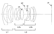
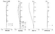
図1は本発明の実施例1の光学系のレンズ断面図である。図2は実施例1の光学系が無限遠物体に合焦したときの収差図である。図3は本発明の実施例2の光学系のレンズ断面図である。図4は実施例2の光学系が無限遠物体に合焦したときの収差図である。図5は本発明の実施例3の光学系のレンズ断面図である。図6は実施例3の光学系が無限遠物体に合焦したときの収差図である。 FIG. 1 is a lens cross-sectional view of an optical system according to Example 1 of the present invention. FIG. 2 is an aberration diagram when the optical system of Example 1 is focused on an object at infinity. FIG. 3 is a lens sectional view of the optical system according to Example 2 of the present invention. FIG. 4 is an aberration diagram when the optical system of Example 2 is focused on an object at infinity. FIG. 5 is a lens cross-sectional view of the optical system according to Example 3 of the present invention. FIG. 6 is an aberration diagram when the optical system of Example 3 is focused on an object at infinity.
図7は本発明の光学系を備えるカメラ(撮像装置)の要部概略図である。 FIG. 7 is a schematic diagram of a main part of a camera (imaging device) provided with the optical system of the present invention.
各実施例の光学系は、ビデオカメラやデジタルカメラそして銀塩フィルムカメラ等の撮像装置に用いられる撮影光学系である。レンズ断面図において、左方が物体側(前方)で、右方が像側(後方)である。 The optical system of each embodiment is a photographing optical system used in an imaging apparatus such as a video camera, a digital camera, or a silver salt film camera. In the lens cross-sectional view, the left side is the object side (front), and the right side is the image side (rear).
尚、各実施例の光学系をプロジェクター等の投射レンズとして用いても良い。このときは、左方がスクリーン、右方が被投射画像となる。 In addition, you may use the optical system of each Example as projection lenses, such as a projector. At this time, the left side is the screen and the right side is the projected image.
レンズ断面図において、iは物体側からのレンズ群の順番を示し、Liは第iレンズ群である。 In the lens cross-sectional view, i indicates the order of the lens groups from the object side, and Li is the i-th lens group.
レンズ断面図において、L1は負の屈折力の第1レンズ群、L2はフォーカス用の正の屈折力の第2レンズ群である。第2レンズ群L2は物体側から像側へ順に正の屈折力の前群L2a、絞り(開口絞り)SP、正の屈折力の後群L2bにより構成されている。 In the lens cross-sectional view, L1 is a first lens unit having a negative refractive power, and L2 is a second lens unit having a positive refractive power for focusing. The second lens unit L2 includes, in order from the object side to the image side, a front group L2a having a positive refractive power, a stop (aperture stop) SP, and a rear group L2b having a positive refractive power.
ここで、屈折力とは光学的パワーのことであり、焦点距離の逆数である。 Here, the refractive power is optical power and is the reciprocal of the focal length.
IPは像面であり、ビデオカメラやデジタルスチルカメラの撮影光学系として使用する際にはCCDセンサやCMOSセンサなどの固体撮像素子(光電変換素子)の撮像面に、銀塩フィルム用カメラのときはフィルム面に相当する感光面が置かれる。 IP is an image plane, and when used as a photographing optical system for a video camera or a digital still camera, on the imaging surface of a solid-state imaging device (photoelectric conversion device) such as a CCD sensor or a CMOS sensor, Is provided with a photosensitive surface corresponding to the film surface.
GRは前群L2a中の最も像側に位置する両凸形状の正レンズである。GFは後群L2b中の最も物体側の面である。 GR is a biconvex positive lens located closest to the image side in the front lens unit L2a. GF is the most object-side surface in the rear group L2b.
収差図においてd,gは順にd線,g線である。ΔM、ΔSはメリディオナル像面、サジタル像面である。倍率色収差はg線によって表している。FnoはFナンバー、Yは像高である。 In the aberration diagram, d and g are d line and g line in this order. ΔM and ΔS are a meridional image plane and a sagittal image plane. Lateral chromatic aberration is represented by the g-line. Fno is the F number, and Y is the image height.
各実施例の光学系は、BFを無限遠物点に合焦時のバックフォーカスとする。fを光学系全系の焦点距離とする。fpを前群中L2aの最も像側に位置する正レンズGRの焦点距離とする。f2aを前群L2aの焦点距離とする。φfを後群中L2bの最も物体側の面GFの屈折力とする。φを光学系全系の屈折力とする。このとき
1.0<BF/f<3.0 ‥‥‥(1)
0.1<fp/f2a<0.5 ‥‥‥(2)
0.7<|φf/φ|<1.5 ‥‥‥(3)
なる条件を満足している。
The optical system of each embodiment uses BF as a back focus when focusing on an object point at infinity. Let f be the focal length of the entire optical system. Let fp be the focal length of the positive lens GR located closest to the image side of L2a in the front group. Let f2a be the focal length of the front lens unit L2a. Let φf be the refractive power of the surface GF closest to the object side of L2b in the rear group. Let φ be the refractive power of the entire optical system. At this time, 1.0 <BF / f <3.0 (1)
0.1 <fp / f2a <0.5 (2)
0.7 <| φf / φ | <1.5 (3)
Is satisfied.
ここで、面の曲率半径をR、面の光入射側と光出射側の媒質の屈折率をn、n’とする。 Here, the radius of curvature of the surface is R, and the refractive indexes of the medium on the light incident side and light emitting side of the surface are n and n '.
このとき屈折力φは、
φa=(n’−n)/R
で定義されるものである。
At this time, the refractive power φ is
φa = (n′−n) / R
Is defined by
条件式(1)は、光学系のレトロ比(Rf=BF/f)を最適に保つための条件式である。 Conditional expression (1) is a conditional expression for keeping the retro ratio (Rf = BF / f) of the optical system optimal.
レトロフォーカス型の光学系において、負の屈折力のレンズ群(第1レンズ群)L1と正の屈折力のレンズ群(第2レンズ群)L2のパワー(屈折力)のバランスとバックフォーカスBFの大小とには相対的な因果関係がある。 In the retrofocus type optical system, the balance of the power (refractive power) of the negative refractive power lens group (first lens group) L1 and the positive refractive power lens group (second lens group) L2 and the back focus BF There is a relative causal relationship between large and small.
長いバックフォーカスを必要とすることは、レトロ比を大きくすることに等しい。また、大きなレトロ比は、負の屈折力のレンズ群の屈折力が著しく大きくなる。そうすると負の屈折力のレンズ群と正の屈折力のレンズ群とのパワーバランスが崩れてきて、光学性能が劣化し、特にペッツヴァール和が悪化し像面湾曲、歪曲等の軸外収差が悪化してくる。そして結果的に光学系が大型化してくる。 Requiring a long back focus is equivalent to increasing the retro ratio. In addition, when the retro ratio is large, the refractive power of the lens unit having a negative refractive power is remarkably increased. As a result, the power balance between the lens unit having a negative refractive power and the lens unit having a positive refractive power is lost, and optical performance is deteriorated. Come on. As a result, the optical system becomes larger.
そこで各実施例では条件式(1)を満足するようにしている。 Therefore, in each embodiment, the conditional expression (1) is satisfied.
条件式(1)の上限を超えると、レトロ比が大きくなるため、負の屈折力の第1レンズ群のパワーが大きくなる。 When the upper limit of conditional expression (1) is exceeded, the retro ratio increases, so the power of the first lens unit having negative refractive power increases.
したがって、本発明のようなレンズ構成の光学系では、ペッツヴァール和の最適な値の設定が困難になり、軸外収差が悪化してしまう。中でも、歪曲と非点収差及び像面湾曲の補正が困難になってしまう。 Therefore, in an optical system having a lens configuration as in the present invention, it becomes difficult to set an optimal value for the Petzval sum, and off-axis aberrations deteriorate. In particular, it is difficult to correct distortion, astigmatism, and field curvature.
また、前玉径も増加し、光学系全体が大型化してしまうため好ましくない。 Also, the front lens diameter is increased, and the entire optical system is enlarged, which is not preferable.
一方、条件式(1)の下限を超えると、レトロ比が小さくなりすぎて、例えば一眼レフカメラに適用する場合、最適な長さのバックフォーカスを確保することが困難になってくる。 On the other hand, when the lower limit of conditional expression (1) is exceeded, the retro ratio becomes too small, and for example, when applied to a single-lens reflex camera, it becomes difficult to ensure an optimal length of back focus.
条件式(2)は絞りSPに最も近い正レンズGRの屈折力を適切に設定することにより、明るいFナンバーを維持しつつ球面収差を少ないレンズ枚数で良好に補正するための条件である。 Conditional expression (2) is a condition for properly correcting spherical aberration with a small number of lenses while maintaining a bright F-number by appropriately setting the refractive power of the positive lens GR closest to the stop SP.
条件式(2)の上限を超え、正レンズGRの屈折力が弱くなりすぎると負の屈折力の第1レンズ群L1と絞りSPより像側の正の屈折力の後群L2bで発生する正の球面収差の補正が困難となる。逆に下限を超え、正レンズGRの屈折力が強くなりすぎると球面収差が負の方向に増大するので良くない。 If the upper limit of conditional expression (2) is exceeded and the refractive power of the positive lens GR becomes too weak, the positive lens generated in the first lens unit L1 having negative refractive power and the rear unit L2b having positive refractive power on the image side from the stop SP. It becomes difficult to correct the spherical aberration. Conversely, if the lower limit is exceeded and the refractive power of the positive lens GR becomes too strong, spherical aberration increases in the negative direction, which is not good.
条件式(3)は後群L2bの最も物体側の面GFの屈折力を規定するものである。 Conditional expression (3) defines the refractive power of the surface GF closest to the object side of the rear group L2b.
一般に、明るい光学系は、正の球面収差が多く発生する。これを補正するために、後群L2bの最も物体側の凹面の曲率(パワー)を強くし、この面において負の球面収差を多く発生させて全系の球面収差を補正するようにしている。 In general, a bright optical system generates a lot of positive spherical aberration. In order to correct this, the curvature (power) of the concave surface closest to the object in the rear group L2b is increased, and a large amount of negative spherical aberration is generated on this surface to correct the spherical aberration of the entire system.
条件式(3)の上限を超えると後群L2bの最も物体側の面(凹面)GFの曲率が弱くなりすぎて、球面収差の補正が困難となる。逆に下限を超えると後群L2bの最も物体側の面(凹面)GFの曲率が強くなりすぎて、サジタルコマ収差の補正が困難となる。 If the upper limit of conditional expression (3) is exceeded, the curvature of the most object-side surface (concave surface) GF of the rear group L2b becomes too weak, making it difficult to correct spherical aberration. On the other hand, if the lower limit is exceeded, the curvature of the most object-side surface (concave surface) GF of the rear group L2b becomes too strong, making it difficult to correct sagittal coma.
尚、各実施例において更に全画面に渡り良好な光学性能を得るためには、条件式(1)〜(3)の数値を次の如く設定するのが良い。 In each embodiment, in order to obtain better optical performance over the entire screen, the numerical values of the conditional expressions (1) to (3) are preferably set as follows.
1.2 <BF/f<2.5 ‥‥‥(1a)
0.2 <fp/f2a<0.4 ‥‥‥(2a)
0.75<|φf/φ|<1.40 ‥‥‥(3a)
以上のように各条件式を満足することにより、諸収差、特に球面収差、コマ収差、非点収差を良好に補正した光学系を得ている。
1.2 <BF / f <2.5 (1a)
0.2 <fp / f2a <0.4 (2a)
0.75 <| φf / φ | <1.40 (3a)
By satisfying the conditional expressions as described above, an optical system in which various aberrations, in particular, spherical aberration, coma aberration, and astigmatism are well corrected is obtained.
特に絞りSPに最も近いところに位置する正レンズGRの屈折力を条件式(2)の如く設定することにより、広画角を図りつつ、球面収差、コマ収差、非点収差等を良好に補正することができるレトロフォーカス型の光学系を得ている。 In particular, by setting the refractive power of the positive lens GR located closest to the aperture stop SP as shown in Conditional Expression (2), spherical aberration, coma, astigmatism, etc. can be corrected well while achieving a wide angle of view. We have obtained a retrofocus type optical system that can.
各実施例の光学系において、好ましくは次の条件式のうち1以上を満足するのが良い。 In the optical system of each embodiment, it is preferable to satisfy one or more of the following conditional expressions.
それによれば各条件式に対応した効果が得られる。 According to this, an effect corresponding to each conditional expression can be obtained.
前群L2aは正レンズと負レンズの接合レンズを有する。このときNpを接合レンズの正レンズの材料の屈折率とする。Nnを接合レンズの負レンズの材料の屈折率とする。このとき
1.05<Np/Nn<1.50 ‥‥‥(4)
2.0<f2a/f<10.0 ‥‥‥(5)
なる条件のうち1以上を満足するのが良い。
The front group L2a has a cemented lens of a positive lens and a negative lens. At this time, Np is the refractive index of the positive lens material of the cemented lens. Let Nn be the refractive index of the material of the negative lens of the cemented lens. At this time, 1.05 <Np / Nn <1.50 (4)
2.0 <f2a / f <10.0 (5)
It is preferable to satisfy one or more of the following conditions.
条件式(4)は前群L2aの接合レンズを構成する正レンズと負レンズの材料の屈折率比を規定するものである。条件式(4)の下限又は上限を超えるとペッツヴァール和の補正が困難となり、像面湾曲等の軸外収差の悪化を招いてしまい、結果的に光学系が大型化してくるので良くない。 Conditional expression (4) defines the refractive index ratio of the materials of the positive lens and the negative lens constituting the cemented lens of the front group L2a. If the lower limit or upper limit of conditional expression (4) is exceeded, correction of the Petzval sum becomes difficult, leading to deterioration of off-axis aberrations such as field curvature, resulting in an increase in the size of the optical system.
条件式(5)は、第2レンズ群L2の前群L2aの焦点距離を規定したものである。条件式(5)の上限を超えると第2レンズ群L2が十分な屈折力を得ることが困難となるので、負の屈折力の第1レンズ群L1で発生する正の球面収差の補正が困難となる。逆に下限を超えると球面収差が負の方向に増大するので良くない。 Conditional expression (5) defines the focal length of the front lens unit L2a of the second lens unit L2. If the upper limit of conditional expression (5) is exceeded, it is difficult for the second lens unit L2 to obtain sufficient refractive power, and therefore it is difficult to correct positive spherical aberration that occurs in the first lens unit L1 having negative refractive power. It becomes. Conversely, if the lower limit is exceeded, the spherical aberration increases in the negative direction, which is not good.
更に好ましくは条件式(4)、(5)の数値範囲を次の如く設定するのが良い。 More preferably, the numerical ranges of conditional expressions (4) and (5) should be set as follows.
1.08<Np/Nn<1.40 ‥‥‥(4a)
3.0<f2a/f<8.0 ‥‥‥(5a)
球面収差とコマ収差や非点収差等の軸外収差をバランス良く補正するには第1レンズ群L1を次の如く構成するのが良い。
1.08 <Np / Nn <1.40 (4a)
3.0 <f2a / f <8.0 (5a)
In order to correct off-axis aberrations such as spherical aberration, coma and astigmatism in a well-balanced manner, the first lens unit L1 is preferably configured as follows.
物体側から像側へ順に物体側に凸面を向けた2つのメニスカス形状の負レンズ、両凸形状の正レンズ、両凹形状の負レンズと正レンズとの接合レンズより構成することである。又は物体側から像側へ順に物体側に凸面を向けた2つのメニスカス形状の負レンズ、両凸形状の正レンズより構成することである。 It consists of two meniscus negative lenses having a convex surface facing the object side in order from the object side to the image side, a biconvex positive lens, and a cemented lens of a biconcave negative lens and a positive lens. Alternatively, it is composed of two negative meniscus lenses having a convex surface facing the object side in order from the object side to the image side, and a biconvex positive lens.
各実施例において、軸外収差と球面収差をバランス良く補正するには、前群L2aを次の如く構成するのが良い。 In each embodiment, in order to correct off-axis aberration and spherical aberration in a balanced manner, the front group L2a is preferably configured as follows.
物体側から像側へ順に、両凸形状の正レンズと両凹形状の負レンズとの接合レンズ、物体側に凹面を向けた負レンズ、両凸形状の正レンズより構成することである。 In order from the object side to the image side, a cemented lens of a biconvex positive lens and a biconcave negative lens, a negative lens having a concave surface facing the object side, and a biconvex positive lens.
又は、物体側から像側へ順に、両凸形状の正レンズと両凹形状の負レンズとの接合レンズ、両凸形状の正レンズより構成することである。 Alternatively, in order from the object side to the image side, a cemented lens of a biconvex positive lens and a biconcave negative lens, and a biconvex positive lens are configured.
又、後群L2bを次の如く構成するのが諸収差を良好に補正するのに好ましい。 The rear group L2b is preferably configured as follows in order to satisfactorily correct various aberrations.
物体側から像側へ順に、物体側に凹面を向けたメニスカス形状の正レンズと像側に凸面を向けたメニスカス形状の負レンズとの接合レンズ、両レンズ面が凸形状の正レンズ、像側に凸面を向けたメニスカス形状の正レンズより構成するのが良い。 Sequentially from the object side to the image side, a cemented lens of a meniscus positive lens with a concave surface facing the object side and a meniscus negative lens with a convex surface facing the image side, a positive lens with both lens surfaces convex, and image side It is preferable that the lens is composed of a meniscus positive lens having a convex surface.
各実施例において、無限遠物体から近距離物体へのフォーカシングは、次のいずれかの方式を用いることができる。 In each embodiment, any of the following methods can be used for focusing from an infinitely distant object to a close object.
(a)第1レンズ群L1を固定(不動)とし、第2レンズ群L2全体を繰り出す(移動する)方式
(b)第1レンズ群L1を固定とし、第2レンズ群L2の後群L2bのみを繰り出す方式
(c)第1レンズ群L1を固定とし、第2レンズ群L2の前群L2aと後群L2bを近づけながら繰り出す方式
尚、オートフォーカス機能を有する撮影光学系として使用する際には、アクチュエータへの負担と、光学性能とのバランスを考慮すると、方式(c)を採用することが最も望ましい。
(A) Method in which the first lens unit L1 is fixed (immobilized), and the entire second lens unit L2 is extended (moved). (B) The first lens unit L1 is fixed, and only the rear unit L2b of the second lens unit L2. (C) A method in which the first lens unit L1 is fixed and the front lens unit L2a and the rear lens unit L2b of the second lens unit L2 are moved close to each other. When used as a photographing optical system having an autofocus function, Considering the balance between the load on the actuator and the optical performance, it is most desirable to adopt the method (c).
各実施例によれば、前述の通りのレンズ構成にすることにより諸収差、特に球面収差、コマ収差、非点収差が良好に補正された撮影画角84°程度と広画角で、しかもFナンバー1.45と明るいレトロフォーカス型の光学系が得られる。 According to each embodiment, with the lens configuration as described above, various aberrations, in particular spherical aberration, coma aberration, and astigmatism are corrected well, with a shooting field angle of about 84 ° and a wide field angle. A bright retrofocus type optical system with a number of 1.45 is obtained.
次に実施例1〜3に示した光学系を撮像装置に適用した実施例を図7を用いて説明する。 Next, an embodiment in which the optical system shown in Embodiments 1 to 3 is applied to an imaging apparatus will be described with reference to FIG.
図7は一眼レフカメラの要部概略図である。図7において、10は実施例1〜3の光学系1を有する撮影光学系である。
FIG. 7 is a schematic diagram of a main part of a single-lens reflex camera. In FIG. 7,
撮影光学系1は保持部材である鏡筒2に保持されている。20はカメラ本体である。カメラ本体20はクイックリターンミラー3、焦点板4、ペンタダハプリズム5、接眼レンズ6等によって構成されている。
The photographing optical system 1 is held by a lens barrel 2 that is a holding member.
クイックリターンミラー3は、撮影光学系10からの光束を上方に反射する。焦点板4は撮影光学系10の像形成位置に配置されている。ペンタダハプリズム5は焦点板4に形成された逆像を正立像に変換する。観察者は、その正立像を接眼レンズ6を介して観察する。
The
7は感光面であり、像を受光するCCDセンサやCMOSセンサ等の固体撮像素子(光電変換素子)や銀塩フィルムが配置される。撮影時にはクイックリターンミラー3が光路から退避して、感光面7上に撮影光学系10によって像側形成される。
Reference numeral 7 denotes a photosensitive surface, on which a solid-state imaging device (photoelectric conversion device) such as a CCD sensor or a CMOS sensor that receives an image, or a silver salt film is disposed. At the time of photographing, the
尚、本発明の光学系は、デジタルカメラ・ビデオカメラ・銀塩フィルム用カメラ等の他に望遠鏡、双眼鏡、複写機、プロジェクター等の光学機器にも適用できる。 The optical system of the present invention can be applied to optical devices such as telescopes, binoculars, copying machines, projectors, etc., in addition to digital cameras, video cameras, silver salt film cameras, and the like.
以下に、実施例1〜3に各々対応する数値実施例1〜3を示す。 The numerical examples 1 to 3 corresponding to the examples 1 to 3 are shown below.
各数値実施例において、iは物体側からの面の順番を示し、riは第i番目(第i面)の曲率半径、diは第i面と第i+1面との間の間隔、ndi、νdiはそれぞれd線を基準とした屈折率、アッベ数を示す。BFはバックフォーカスである。*はその面が非球面であることを示す。
(非球面データ)には、非球面を次式で表した場合の非球面係数を示す。
In each numerical example, i indicates the order of the surfaces from the object side, ri is the i-th (i-th surface) radius of curvature, di is the distance between the i-th surface and the (i + 1) -th surface, ndi, νdi Represents a refractive index and an Abbe number based on the d-line, respectively. BF is a back focus. * Indicates that the surface is aspherical.
(Aspheric data) shows the aspheric coefficient when the aspheric surface is expressed by the following equation.

但し、
x:光軸方向の基準面からの変位量である。
h:光軸に対して垂直な方向の高さである。
R:ベースとなる2次曲面の半径である。
Cn:n次の非球面係数である。
なお、「E−Z」の表示は「10−Z」を意味する。
However,
x: A displacement amount from the reference plane in the optical axis direction.
h: Height in the direction perpendicular to the optical axis.
R: radius of a quadric surface as a base.
Cn: n-order aspherical coefficient.
It should be noted that the display of the "E-Z" means "10 -Z".
又前述の各条件式と数値実施例における諸数値との関係を表−1に示す。 Table 1 shows the relationship between the above-described conditional expressions and numerical values in the numerical examples.
L1:第1レンズ群
L2:第2レンズ群
L2a:第2レンズ群の前群
L2b:第2レンズ群の後群
GR:前群の中で最も像側の正レンズ
GF:後群の中で最も物体側の面
SP:開口絞り
IP:像面
d:d線
g:g線
ΔM:メリディオナル像面
ΔS:サジタル像面
L1: First lens group L2: Second lens group L2a: Front group L2b of the second lens group: Rear group of the second lens group GR: Positive lens GF closest to the image in the front group: GF in the rear group Surface SP closest to the object side: Aperture stop IP: Image plane d: d line g: g line ΔM: meridional image plane ΔS: sagittal image plane
Claims (5)
無限遠物体から近距離物体へのフォーカスに際して、前記第1レンズ群は不動であり、前記第2レンズ群の全体が物体側へ移動する光学系であって、
BFを無限遠物点に合焦したときのバックフォーカス、fを光学系全系の焦点距離、fpを前記前群中の最も像側に位置する正レンズの焦点距離、f2aを前記前群の焦点距離、φfを前記後群中の最も物体側のレンズ面の屈折力、φを光学系全系の屈折力とするとき、
1.0<BF/f<3.0
0.336≦fp/f2a<0.5
0.7<|φf/φ|<1.5
なる条件を満足することを特徴とする光学系。 A first lens group having a negative refractive power and a second lens group having a positive refractive power are arranged in order from the object side to the image side, and the second lens group is arranged in order from the object side to the image side. The front group has a biconvex positive lens closest to the image side, and the rear group has a stop closest to the object side,
When focusing from an object at infinity to an object at a short distance, the first lens group does not move, and the entire second lens group moves toward the object side,
Back focus when BF is focused on an object point at infinity, f is the focal length of the entire optical system, fp is the focal length of the positive lens located closest to the image side in the front group, and f2a is the front group When the focal length, φf is the refractive power of the lens surface closest to the object in the rear group, and φ is the refractive power of the entire optical system ,
1.0 <BF / f <3.0
0.336 ≦ fp / f2a <0.5
0.7 <| φf / φ | <1.5
An optical system characterized by satisfying the following conditions.
無限遠物体から近距離物体へのフォーカスに際して、前記第1レンズ群は不動であり、前記第2レンズ群の前記前群と前記後群は、互いに近づきながら物体側へ移動する光学系であって、When focusing from an object at infinity to an object at a short distance, the first lens group does not move, and the front group and the rear group of the second lens group move toward the object side while approaching each other. ,
BFを無限遠物点に合焦したときのバックフォーカス、fを光学系全系の焦点距離、fpを前記前群中の最も像側に位置する正レンズの焦点距離、f2aを前記前群の焦点距離、φfを前記後群中の最も物体側のレンズ面の屈折力、φを光学系全系の屈折力とするとき、Back focus when BF is focused on an object point at infinity, f is the focal length of the entire optical system, fp is the focal length of the positive lens located closest to the image side in the front group, and f2a is the front group When the focal length, φf is the refractive power of the lens surface closest to the object in the rear group, and φ is the refractive power of the entire optical system,
1.0<BF/f<3.0 1.0 <BF / f <3.0
0.336≦fp/f2a<0.5 0.336 ≦ fp / f2a <0.5
0.7<|φf/φ|<1.5 0.7 <| φf / φ | <1.5
なる条件を満足することを特徴とする光学系。 An optical system characterized by satisfying the following conditions.
1.05<Np/Nn<1.50
なる条件を満足することを特徴とする請求項1又は2に記載の光学系。 The front group includes a cemented lens of a positive lens and a negative lens, and Np is a refractive index of a material of the positive lens of the cemented lens and Nn is a refractive index of a material of the negative lens of the cemented lens.
1.05 <Np / Nn <1.50
Optical system according to claim 1 or 2, characterized by satisfying the following condition.
なる条件を満足することを特徴とする請求項1乃至3のいずれか1項に記載の光学系。 2.0 <f2a / f <10.0
Optical system according to any one of claims 1 to 3, characterized by satisfying the following condition.
Priority Applications (2)
| Application Number | Priority Date | Filing Date | Title |
|---|---|---|---|
| JP2007281530A JP5111056B2 (en) | 2007-10-30 | 2007-10-30 | Optical system and imaging apparatus having the same |
| US12/206,418 US7715117B2 (en) | 2007-10-30 | 2008-09-08 | Optical system and image pickup apparatus using the same |
Applications Claiming Priority (1)
| Application Number | Priority Date | Filing Date | Title |
|---|---|---|---|
| JP2007281530A JP5111056B2 (en) | 2007-10-30 | 2007-10-30 | Optical system and imaging apparatus having the same |
Publications (3)
| Publication Number | Publication Date |
|---|---|
| JP2009109723A JP2009109723A (en) | 2009-05-21 |
| JP2009109723A5 JP2009109723A5 (en) | 2010-12-09 |
| JP5111056B2 true JP5111056B2 (en) | 2012-12-26 |
Family
ID=40582476
Family Applications (1)
| Application Number | Title | Priority Date | Filing Date |
|---|---|---|---|
| JP2007281530A Active JP5111056B2 (en) | 2007-10-30 | 2007-10-30 | Optical system and imaging apparatus having the same |
Country Status (2)
| Country | Link |
|---|---|
| US (1) | US7715117B2 (en) |
| JP (1) | JP5111056B2 (en) |
Families Citing this family (18)
| Publication number | Priority date | Publication date | Assignee | Title |
|---|---|---|---|---|
| JP5418745B2 (en) * | 2008-03-04 | 2014-02-19 | 株式会社ニコン | Photographic lens and optical apparatus provided with the photographic lens |
| TW201037354A (en) * | 2009-04-15 | 2010-10-16 | Young Optics Inc | Fixed-focus lens |
| TW201113553A (en) * | 2009-10-13 | 2011-04-16 | Young Optics Inc | Fixed-focus lens |
| CN103081458A (en) * | 2010-08-27 | 2013-05-01 | 3M创新有限公司 | Projection lens for projection display systems |
| US8717686B2 (en) * | 2010-11-22 | 2014-05-06 | Nikon Corporation | Optical system, optical apparatus and optical system manufacturing method |
| JP6214311B2 (en) | 2013-10-03 | 2017-10-18 | キヤノン株式会社 | Optical system and imaging apparatus having the same |
| JP6523289B2 (en) | 2014-08-05 | 2019-05-29 | オリンパス株式会社 | Imaging optical system and optical apparatus provided with the same |
| JP6383214B2 (en) | 2014-08-05 | 2018-08-29 | オリンパス株式会社 | Imaging optical system and optical apparatus including the same |
| JP6400104B2 (en) | 2014-08-05 | 2018-10-03 | オリンパス株式会社 | Imaging optical system and optical apparatus provided with the same |
| WO2016194112A1 (en) | 2015-06-01 | 2016-12-08 | オリンパス株式会社 | Single-focus optical system and optical device provided with same |
| JP6558838B2 (en) | 2015-06-01 | 2019-08-14 | オリンパス株式会社 | Single focus optical system and optical apparatus including the same |
| WO2016194110A1 (en) | 2015-06-01 | 2016-12-08 | オリンパス株式会社 | Single-focus optical system and optical device provided with same |
| WO2016194109A1 (en) | 2015-06-01 | 2016-12-08 | オリンパス株式会社 | Single-focus optical system and optical device provided with same |
| JPWO2016194111A1 (en) * | 2015-06-01 | 2018-03-22 | オリンパス株式会社 | Single focus optical system and optical apparatus including the same |
| JP6512955B2 (en) * | 2015-06-11 | 2019-05-15 | コニカミノルタ株式会社 | Wide-angle lens, imaging optical device and digital device |
| WO2017130265A1 (en) | 2016-01-25 | 2017-08-03 | オリンパス株式会社 | Single-focus optical system and optical device provided therewith |
| JP6969071B2 (en) * | 2016-03-11 | 2021-11-24 | 株式会社ニコン | Optical system, optical device |
| JP6605120B2 (en) | 2016-03-30 | 2019-11-13 | オリンパス株式会社 | Single focus optical system and optical apparatus including the same |
Family Cites Families (7)
| Publication number | Priority date | Publication date | Assignee | Title |
|---|---|---|---|---|
| JPS5510049B2 (en) * | 1972-07-04 | 1980-03-13 | ||
| US4957355A (en) * | 1986-12-24 | 1990-09-18 | Nikor Corp. | Retrofocus type lens system |
| JPH0682689A (en) | 1992-09-03 | 1994-03-25 | Canon Inc | Retrofocus type lens |
| JP3352264B2 (en) * | 1994-12-21 | 2002-12-03 | キヤノン株式会社 | Retrofocus type lens and camera having the same |
| JP4776796B2 (en) | 2001-03-23 | 2011-09-21 | キヤノン株式会社 | Zoom lens and optical apparatus using the same |
| US7239456B2 (en) * | 2004-03-31 | 2007-07-03 | Nikon Corporation | Super wide-angle lens system and image-capturing device using the same |
| KR101457415B1 (en) * | 2008-06-26 | 2014-11-03 | 삼성전자주식회사 | Lens optical system |
-
2007
- 2007-10-30 JP JP2007281530A patent/JP5111056B2/en active Active
-
2008
- 2008-09-08 US US12/206,418 patent/US7715117B2/en active Active
Also Published As
| Publication number | Publication date |
|---|---|
| US7715117B2 (en) | 2010-05-11 |
| JP2009109723A (en) | 2009-05-21 |
| US20090109551A1 (en) | 2009-04-30 |
Similar Documents
| Publication | Publication Date | Title |
|---|---|---|
| JP5111056B2 (en) | Optical system and imaging apparatus having the same | |
| US10073252B2 (en) | Optical system and image pickup apparatus including the same | |
| JP5441377B2 (en) | Single focus optical system and imaging apparatus having the same | |
| JP6537331B2 (en) | Optical system and imaging apparatus having the same | |
| JP5197242B2 (en) | Zoom lens and imaging apparatus having the same | |
| US8223439B2 (en) | Optical system and image pickup apparatus having the optical system | |
| US9684155B2 (en) | Optical system and image pickup apparatus including the same | |
| JP6667297B2 (en) | Optical system and imaging apparatus having the same | |
| JP5582706B2 (en) | Optical system and imaging apparatus having the same | |
| US10025075B2 (en) | Zoom lens and image pickup apparatus including the same | |
| US11131829B2 (en) | Zoom lens and image pickup apparatus | |
| JP4593971B2 (en) | Zoom lens and imaging apparatus having the same | |
| JP4827454B2 (en) | Zoom lens and imaging apparatus having the same | |
| JP2015028530A (en) | Zoom lens and imaging apparatus including the same | |
| CN110709747B (en) | Optical system for image pickup and image pickup apparatus | |
| JP4921044B2 (en) | Zoom lens and imaging apparatus having the same | |
| JP4617111B2 (en) | Zoom lens and imaging apparatus having the same | |
| JP5959872B2 (en) | Zoom lens and imaging apparatus having the same | |
| JP2010243737A (en) | Variable imaging optical system | |
| JP2012047869A (en) | Rear converter lens and imaging optical system having the same | |
| JP5078498B2 (en) | Zoom lens and imaging apparatus having the same | |
| JP2012123155A (en) | Optical system | |
| JP6983541B2 (en) | Imaging optical system and imaging equipment using it | |
| US8593740B2 (en) | Retrofocus-type wide angle lens and camera including the lens | |
| JP5058634B2 (en) | Zoom lens and imaging apparatus having the same |
Legal Events
| Date | Code | Title | Description |
|---|---|---|---|
| A521 | Request for written amendment filed |
Free format text: JAPANESE INTERMEDIATE CODE: A523 Effective date: 20101026 |
|
| A621 | Written request for application examination |
Free format text: JAPANESE INTERMEDIATE CODE: A621 Effective date: 20101026 |
|
| A977 | Report on retrieval |
Free format text: JAPANESE INTERMEDIATE CODE: A971007 Effective date: 20120607 |
|
| A131 | Notification of reasons for refusal |
Free format text: JAPANESE INTERMEDIATE CODE: A131 Effective date: 20120612 |
|
| A521 | Request for written amendment filed |
Free format text: JAPANESE INTERMEDIATE CODE: A523 Effective date: 20120808 |
|
| TRDD | Decision of grant or rejection written | ||
| A01 | Written decision to grant a patent or to grant a registration (utility model) |
Free format text: JAPANESE INTERMEDIATE CODE: A01 Effective date: 20120911 |
|
| A01 | Written decision to grant a patent or to grant a registration (utility model) |
Free format text: JAPANESE INTERMEDIATE CODE: A01 |
|
| A61 | First payment of annual fees (during grant procedure) |
Free format text: JAPANESE INTERMEDIATE CODE: A61 Effective date: 20121009 |
|
| FPAY | Renewal fee payment (event date is renewal date of database) |
Free format text: PAYMENT UNTIL: 20151019 Year of fee payment: 3 |
|
| R151 | Written notification of patent or utility model registration |
Ref document number: 5111056 Country of ref document: JP Free format text: JAPANESE INTERMEDIATE CODE: R151 |
|
| FPAY | Renewal fee payment (event date is renewal date of database) |
Free format text: PAYMENT UNTIL: 20151019 Year of fee payment: 3 |
|
| RD03 | Notification of appointment of power of attorney |
Free format text: JAPANESE INTERMEDIATE CODE: R3D03 |