JP4508552B2 - gear - Google Patents
gear Download PDFInfo
- Publication number
- JP4508552B2 JP4508552B2 JP2003142893A JP2003142893A JP4508552B2 JP 4508552 B2 JP4508552 B2 JP 4508552B2 JP 2003142893 A JP2003142893 A JP 2003142893A JP 2003142893 A JP2003142893 A JP 2003142893A JP 4508552 B2 JP4508552 B2 JP 4508552B2
- Authority
- JP
- Japan
- Prior art keywords
- tooth
- gear
- teeth
- tooth row
- groove
- Prior art date
- Legal status (The legal status is an assumption and is not a legal conclusion. Google has not performed a legal analysis and makes no representation as to the accuracy of the status listed.)
- Expired - Fee Related
Links
Images


Landscapes
- Gears, Cams (AREA)
Description
【0001】
【発明の属する技術分野】
本発明は、位相した複数の歯列を備えた歯車に係る技術分野に属する。
【0002】
【従来の技術】
最近、精密機器類の駆動伝達機構では、噛合い率を大きくし各歯に掛かる荷重を分散して耐久性を高めるために、位相した複数の歯列を備えた歯車が多用されるようになってきている。
【0003】
従来、位相した複数の歯列を備えた歯車としては、例えば、以下に記載のものが知られている。
【特許文献1】
特許第2710861号公報
特許文献1には、一体成形によって単一の歯車基板の外周面に円周ピッチが同一の歯列が複数形成され、各歯列が隣合う歯列に対して円周方向へ1/2ピッチずらされ、各歯列の各歯の歯元部分が隣合う歯列の前後の歯元部分の一部に対して均等な交差面をもって一体化された歯車が記載されている。
【特許文献2】
特開平7−83313号公報
特許文献2には、各歯の歯元径を異ならせ、各歯の間に小さい歯元径の歯底よりも小さな径の面を底とする環状の溝(隙間)が設けられた歯車が記載されている。
【0004】
特許文献1に係る歯車は、各歯の交差面で歯元を補強することができるという利点を有している。特許文献2に係る歯車は、溝で各歯の互いの干渉を遮断して騒音を低減するとともに、溝を潤滑油の油溜として機能させることができる利点を有している。
【0005】
【発明が解決しようとする課題】
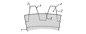
特許文献1では、前述の特許文献2に係る歯車の利点を得るために溝4を構成しようとすると、図12に示すように、溝4の底5がジクザクになってしまい、歯列a,bが溝4を介して離間する格好になってしまうにもかかわらず、各歯列a,bの歯2が狭小な交差面3のみで一体化されているため、歯元の補強機能が低下して、特に合成樹脂材で形成されている場合に噛合いの際に歯2が弾性で曲がる倒れ変形が生じやすくなるという問題点がある。
【0006】
本発明は、このような問題点を考慮してなされたもので、歯の倒れ変形を引起こすことなく歯列の間に溝を設けた歯車を提供することを課題とする。
【0007】
【課題を解決するための手段】
前述の課題を解決するため、本発明に係る歯車は、次のような手段を採用する。
【0008】
即ち、請求項1では、一体成形によって単一の歯車基板の外周面に円周ピッチが同一の歯列が複数形成され、各歯列が隣合う歯列に対して円周方向へ1/2ピッチずらされた歯車において、一の歯列と他の歯列とが離間して形成され、かつ歯列間にピッチ円径の外周面を有する均一幅の連結部が設けられていることを特徴とする。
【0009】
この手段では、特許文献1で予想された溝のジクザグの底を連続させることで、歯の交差面に溝の底の連続による容積拡張部分を追加して歯元の補強機能の低下を防止することができ、歯の倒れ変形を引起こすことなく歯列の間に溝を設けることができる。また、この手段では、歯の厚さを規定するピッチ円まで溝の深さが確保され歯車基板の中心から溝の底までが円板形となる。さらに、この手段では、歯車基板の軸方向へ2分割構造の金型の開閉方向を設定して成形することができ、多分割構造の金型を使用しなくても成形することが可能である。さらにまた、歯車基板の径方向へ開閉されるサイドプレート等からなる金型を使用しなくてすむため、溝を無用に摩擦,擦過することがなく、溝を精密に成形することができる。
【0010】
また、請求項2では、請求項1の歯車において、前記連結部に界面を有するように、前記一の歯列と前記他の歯列とが合成樹脂により二色成形されていることを特徴とする。
【0011】
この手段では、歯車基板が一方の歯列と他方の歯列とで非同一材質で形成でき、何等不都合なく請求項1の構成から生ずる作用,効果と同様の作用,効果が奏される。
【0012】
また、請求項3では、請求項1の歯車において、前記連結部に界面を有するように、前記一の歯列と前記他の歯列とが金属材のアモルファス結合で一体成形されていることを特徴とする。
【0013】
この手段では、歯車基板1が一方の歯列a側と他方の歯列b側とで同一金属材で形成でき、何等不都合なく請求項1の構成から生ずる作用,効果と同様の作用,効果が奏される。
【0014】
【発明の実施の形態】
以下、本発明に係る歯車の実施の形態を図1〜図11に基づいて説明する。
【0015】
図1〜図9は、本発明に係る歯車の実施の形態(1)を示すものである。
【0016】
この実施の形態では、同一の歯幅Waの2列の歯列a,bを備えた平歯車からなるものを示してある。
【0017】
この実施の形態は、図1に示すように、中心に駆動軸,従動軸等を挿通可能な軸孔6が貫通形成された歯車基板1に構成されている。
【0018】
合成樹脂材等の一体成形によって形成された単一の歯車基板1の外周面には、円周ピッチが同一の歯列a,bが2列形成されている。そして、一方の歯列aは、図3に示すように、他方の歯列bに対して円周方向へ1/2ピッチhpずらされている。各歯列a,bの各歯2は、歯元部分が他方(一方)の歯列a,bの前後の歯2の歯元部分の一部に対してほぼ三角状の交差面3をもって一体化されている。
【0019】
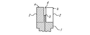
さらに、歯車基板1の外周面には、両歯列a,bの中間から中心に向けて環状の溝4が設けられている。溝4の底5は、前述の交差面3の頂部Pを結ぶ円周面からなる面に連続されている。即ち、図2(図12との対比で)に示すように、歯2の間において溝4の底5を歯幅方向へ拡幅し、拡幅による容積拡張部分Qを交差面3に追加した格好になっている。この結果、歯車基板1は、中心から溝4の底5までが円板形(リング形)となっている。従って、全体では、円板を介して2つの位相した歯車が積層一体化されたような構造になっている。
【0020】
交差面3の頂部P(溝4の底5)については、歯2の厚さを規定することになるピッチ円R付近に位置させるのが好ましい。
【0021】
この実施の形態によると、特許文献2と同様に、溝4で歯列a,bの互いの干渉を遮断して騒音を低減するとともに、溝4を潤滑油の油溜として機能させることができる。
【0022】
さらに、この実施の形態によると、特許文献1で三角状であった交差面3に容積拡張部分Qが追加されて、両歯列a,bの一体性が強化されているため、歯列a,bが溝4を介して離間する格好になっても、歯元の補強機能が低下することがない。このため、噛合い(正逆両回転の)の際に歯2が倒れ変形することがない。特に、交差面3,容積拡張部分Qが歯車基板1の全周に連続し、歯2の歯幅Waが歯元側で溝4の幅分を追加した歯幅Wa’に拡大されていることも、両歯列a,bの一体性の強化に寄与する。また、溝4の底5が交差面3の頂部Pを結ぶ円周面からなる面に連続されて、溝4周りに無用の凹凸構造が形成されていないため、噛合いの際の荷重の応力が一部に集中するようなことはない。
【0023】
なお、溝4の底5が歯2の厚さを規定することになるピッチ円R付近に位置されているため、溝の底5が噛合いの障害になる等の不都合を生ずるおそれはない。
【0024】
さらに、この実施の形態によると、図8,図9に示すように、歯車基板1の軸方向へ2分割構造の金型10,20の開閉方向を設定して成形することができる。即ち、溝4の底が交差面3の頂部Pを結ぶ面に連続して、歯車基板1の軸方向にアンダカット部分が形成されないため、多分割構造の金型を使用しなくても成形することが可能である。また、歯車基板1の径方向へ開閉されるサイドプレート等(溝3の部分に侵入される)からなる金型を使用しなくてすむため、溝4を無用に摩擦,擦過することがなく、溝4を精密に成形することができる。
【0025】
図10は、本発明に係る歯車の実施の形態(2)を示すものである。
【0026】
この実施の形態では、一方の歯列aの歯2の歯幅Waと他方の歯列bの歯2の歯幅Wbとを異ならせている。
【0027】
この実施の形態でも、何等不都合なく前述の実施の形態(1)と同様の作用,効果が奏される。
【0028】
図11は、本発明に係る歯車の実施の形態(3)を示すものである。
【0029】
この実施の形態では、歯車基板1が一方の歯列a側と他方の歯列b側とで非同一材質で形成されている。
【0030】
この実施の形態でも、例えば、合成樹脂材の2色成形で両材質の界面が完全に融着されたり、金属材でアモルファス結合で両材質の界面が完全に結合されている状態の一体成形であれば、何等不都合なく前述の実施の形態(1)と同様の作用,効果が奏される。
【0031】
以上、図示した実施の形態の外に、歯列a,bを3列以上設けることも可能である。
【0032】
【発明の効果】
以上のように、本発明に係る歯車は、特許文献1で予想される溝のジクザグの底を連続させることで、歯の交差面に溝の底の連続による容積拡張部分を追加して歯元の補強機能の低下を防止するため、歯の倒れ変形を引起こすことなく歯列の間に溝を設けることができる効果がある。
【図面の簡単な説明】
【図1】 本発明に係る歯車の実施の形態(1)を示す斜視図である。
【図2】 従来例との相違点を説明する図1の要部の拡大図である。
【図3】 図1の一部の拡大正面図である。
【図4】 図3のA−A線断面図である。
【図5】 図4のB−B線断面図である。
【図6】 図4のC−C線断面図である。
【図7】 図4のD−D線断面図である。
【図8】 図1の製造例を示す要部の斜視図である。
【図9】 図7の動作図である。
【図10】 本発明に係る歯車の実施の形態(2)を示す要部の断面である。
【図11】 本発明に係る歯車の実施の形態(3)を示す要部の断面図である。
【図12】 特許文献1をベースに発明者が工夫した未公知の歯車の一部を示す斜視図である。
【符号の説明】
1 歯車基板
2 歯
3 交差面
4 溝
5 底
a,b 歯列[0001]
BACKGROUND OF THE INVENTION
The present invention belongs to a technical field related to a gear having a plurality of phased teeth.
[0002]
[Prior art]
Recently, in drive transmission mechanisms of precision instruments, gears with a plurality of phased rows of teeth have been frequently used in order to increase the meshing rate and disperse the load applied to each tooth to enhance durability. It is coming.
[0003]
Conventionally, for example, gears described below are known as gears having a plurality of phased tooth rows.
[Patent Document 1]
Japanese Patent No. 2710861
In Patent Document 1, a plurality of tooth rows having the same circumferential pitch are formed on the outer peripheral surface of a single gear substrate by integral molding , and each tooth row is ½ pitch in the circumferential direction with respect to the adjacent tooth row . A gear is described in which the tooth base portions of the respective teeth in each tooth row are integrated with a uniform intersection surface with respect to a part of the tooth root portions before and after the adjacent tooth row .
[Patent Document 2]
The JP-A 7-83313 Patent
[0004]
The gear according to Patent Document 1 has an advantage that the tooth root can be reinforced at the intersecting surface of each tooth . The gear according to
[0005]
[Problems to be solved by the invention]
In Patent Document 1, if the
[0006]
The present invention has been made in consideration of such problems, and an object of the present invention is to provide a gear in which grooves are provided between tooth rows without causing the teeth to fall down.
[0007]
[Means for Solving the Problems]
In order to solve the above-described problems, the gear according to the present invention employs the following means.
[0008]
That is, according to the first aspect, a plurality of tooth rows having the same circumferential pitch are formed on the outer peripheral surface of a single gear substrate by integral molding, and each tooth row is ½ in the circumferential direction with respect to the adjacent tooth row. in pitch staggered gears, they are spaced apart with one teeth and other dentition, and the connecting portion of the uniform width is provided having an outer peripheral surface of the pitch circle diameter between the teeth It is characterized by.
[0009]
In this means, by continuing the zigzag bottom of the groove expected in Patent Document 1, a volume expansion portion due to the continuous bottom of the groove is added to the intersecting surface of the teeth to prevent a reduction in the reinforcing function of the tooth root. It is possible to provide a groove between the dentitions without causing the teeth to fall down. Further, with this means, the depth of the groove is ensured up to the pitch circle that defines the thickness of the teeth, and the shape from the center of the gear substrate to the bottom of the groove is a disk shape. Furthermore, with this means, the mold can be formed by setting the opening / closing direction of the two-part structure mold in the axial direction of the gear substrate, and can be formed without using a multi-part structure mold. . Furthermore, since it is not necessary to use a mold made of a side plate or the like that opens and closes in the radial direction of the gear substrate, the groove can be precisely formed without unnecessary rubbing and rubbing.
[0010]
According to a second aspect of the present invention , in the gear according to the first aspect, the one tooth row and the other tooth row are two-color molded with a synthetic resin so as to have an interface at the connecting portion. To do.
[0011]
In this means, the gear substrate can be formed of non-identical material for one tooth row and the other tooth row, and the same operation and effect as those obtained from the configuration of claim 1 can be achieved without any inconvenience.
[0012]
According to a third aspect of the present invention , in the gear according to the first aspect, the one tooth row and the other tooth row are integrally formed by an amorphous bond of a metal material so as to have an interface at the connecting portion. Features.
[0013]
In this means, the gear base plate 1 can be formed of the same metal material on the one tooth row a side and the other tooth row b side, and there is no inconvenience. Played.
[0014]
DETAILED DESCRIPTION OF THE INVENTION
Embodiments of a gear according to the present invention will be described below with reference to FIGS.
[0015]
1 to 9 show an embodiment (1) of a gear according to the present invention.
[0016]
In the present embodiment, a spur gear having two tooth rows a and b having the same tooth width Wa is shown.
[0017]
In this embodiment, as shown in FIG. 1, a gear substrate 1 is formed in which a shaft hole 6 through which a drive shaft, a driven shaft and the like can be inserted is formed at the center.
[0018]
Two rows of tooth rows a and b having the same circumferential pitch are formed on the outer peripheral surface of a single gear substrate 1 formed by integral molding of a synthetic resin material or the like. Then, as shown in FIG. 3, one tooth row a is shifted by 1/2 pitch hp in the circumferential direction with respect to the other tooth row b. Each
[0019]
Further, an
[0020]
The top portion P (
[0021]
According to this embodiment, similarly to
[0022]
Furthermore, according to this embodiment, since the volume expansion portion Q is added to the
[0023]
Since the
[0024]
Furthermore, according to this embodiment, as shown in FIGS. 8 and 9, it is possible to mold by setting the opening / closing direction of the
[0025]
FIG. 10 shows an embodiment (2) of the gear according to the present invention.
[0026]
In this embodiment, the tooth width Wa of the
[0027]
Even in this embodiment, the same operations and effects as those of the above-described embodiment (1) can be achieved without any inconvenience.
[0028]
FIG. 11 shows an embodiment (3) of the gear according to the present invention.
[0029]
In this embodiment, the gear board 1 is formed of non-identical materials on one tooth row a side and the other tooth row b side.
[0030]
Also in this embodiment, for example, two-color molding of a synthetic resin material is used to integrally fuse the interfaces between the two materials, or an integral molding in which the interfaces between the two materials are completely bonded by an amorphous bond with a metal material. If there are any, the same operations and effects as those of the above-described embodiment (1) can be achieved without any inconvenience.
[0031]
As described above, it is also possible to provide three or more rows of teeth a and b in addition to the illustrated embodiment.
[0032]
【The invention's effect】
As described above, in the gear according to the present invention, the bottom of the zigzag of the groove expected in Patent Document 1 is made continuous, thereby adding a volume expansion portion due to the continuous bottom of the groove to the tooth intersection surface. In order to prevent the lowering of the reinforcing function, there is an effect that grooves can be provided between the dentitions without causing the teeth to fall down.
[Brief description of the drawings]
FIG. 1 is a perspective view showing an embodiment (1) of a gear according to the present invention.
FIG. 2 is an enlarged view of a main part of FIG. 1 for explaining a difference from the conventional example.
FIG. 3 is an enlarged front view of a part of FIG. 1;
4 is a cross-sectional view taken along line AA in FIG.
5 is a cross-sectional view taken along line BB in FIG.
6 is a cross-sectional view taken along the line CC in FIG.
7 is a cross-sectional view taken along the line DD of FIG.
8 is a perspective view of a main part showing the manufacturing example of FIG. 1. FIG.
9 is an operation diagram of FIG. 7. FIG.
FIG. 10 is a cross-sectional view of a relevant part showing Embodiment (2) of the gear according to the present invention.
FIG. 11 is a cross-sectional view of a main part showing an embodiment (3) of a gear according to the present invention.
12 is a perspective view showing a part of an unknown gear devised by the inventor based on Patent Document 1. FIG.
[Explanation of symbols]
1
Claims (3)
一の歯列と他の歯列とが離間して形成され、かつ歯列間にピッチ円径の外周面を有する均一幅の連結部が設けられていることを特徴とする歯車。In a gear in which a plurality of tooth rows having the same circumferential pitch are formed on the outer peripheral surface of a single gear substrate by integral molding, and each tooth row is shifted by 1/2 pitch in the circumferential direction with respect to the adjacent tooth row,
Gear, wherein a connecting portion of one teeth and are spaced apart and the other row of teeth, and uniform width having an outer peripheral surface of the pitch circle diameter between the teeth is provided.
Priority Applications (1)
| Application Number | Priority Date | Filing Date | Title |
|---|---|---|---|
| JP2003142893A JP4508552B2 (en) | 2003-05-21 | 2003-05-21 | gear |
Applications Claiming Priority (1)
| Application Number | Priority Date | Filing Date | Title |
|---|---|---|---|
| JP2003142893A JP4508552B2 (en) | 2003-05-21 | 2003-05-21 | gear |
Publications (2)
| Publication Number | Publication Date |
|---|---|
| JP2004346989A JP2004346989A (en) | 2004-12-09 |
| JP4508552B2 true JP4508552B2 (en) | 2010-07-21 |
Family
ID=33530823
Family Applications (1)
| Application Number | Title | Priority Date | Filing Date |
|---|---|---|---|
| JP2003142893A Expired - Fee Related JP4508552B2 (en) | 2003-05-21 | 2003-05-21 | gear |
Country Status (1)
| Country | Link |
|---|---|
| JP (1) | JP4508552B2 (en) |
Families Citing this family (1)
| Publication number | Priority date | Publication date | Assignee | Title |
|---|---|---|---|---|
| JP7301281B2 (en) * | 2019-11-25 | 2023-07-03 | 株式会社リコー | Gears, drive transmission devices and image forming devices |
Family Cites Families (5)
| Publication number | Priority date | Publication date | Assignee | Title |
|---|---|---|---|---|
| JPS54142775U (en) * | 1978-03-28 | 1979-10-03 | ||
| JP2710861B2 (en) * | 1990-09-20 | 1998-02-10 | 株式会社チバダイス | Tooth wheel |
| JPH074474A (en) * | 1993-06-16 | 1995-01-10 | Canon Inc | Gear and power transmission device having the gear |
| JPH0783313A (en) * | 1993-07-19 | 1995-03-28 | Mitsubishi Materials Corp | Bevel gear with web |
| JPH0783314A (en) * | 1993-09-20 | 1995-03-28 | Canon Inc | Drive gear |
-
2003
- 2003-05-21 JP JP2003142893A patent/JP4508552B2/en not_active Expired - Fee Related
Also Published As
| Publication number | Publication date |
|---|---|
| JP2004346989A (en) | 2004-12-09 |
Similar Documents
| Publication | Publication Date | Title |
|---|---|---|
| US7698964B2 (en) | Gear | |
| US8794096B2 (en) | Gearwheel and method for manufacturing a gearwheel | |
| US6993993B2 (en) | Sheet metal outsert-molded gear | |
| CN100453846C (en) | Wave gear drive with wide range tooth profile | |
| MX2009000242A (en) | Bevel gear. | |
| US3733921A (en) | Reinforced plastic gear | |
| JP4508552B2 (en) | gear | |
| JP2008008322A (en) | Worm wheel and worm gear | |
| JP7517921B2 (en) | gear | |
| JPH0643121B2 (en) | Components made of polymeric material reinforced by a particularly fibrous filler | |
| JP2008232432A (en) | Injection-molded resin face gear | |
| JP2710861B2 (en) | Tooth wheel | |
| JP3910022B2 (en) | Cyclic resin molded product | |
| JP5890690B2 (en) | Steering shaft | |
| JP7071208B2 (en) | Gears, gear manufacturing methods, and injection molds used to manufacture gears | |
| JP3552108B2 (en) | Wafer polishing equipment | |
| KR101340222B1 (en) | Pulley for use with toothed belt | |
| JPH0596564A (en) | Inorganic material gear | |
| JP2000110919A (en) | Molded gear of synthetic resin | |
| JP3596131B2 (en) | Injection molded gear | |
| JP2001336611A (en) | Mold gear | |
| JP2004132433A (en) | Pulley with flange and method of manufacturing the same | |
| JPH0272259A (en) | Gear made of synthetic resin | |
| JP2787741B2 (en) | Planetary gear transmission | |
| JP4004922B2 (en) | Segment type friction material |
Legal Events
| Date | Code | Title | Description |
|---|---|---|---|
| A621 | Written request for application examination |
Free format text: JAPANESE INTERMEDIATE CODE: A621 Effective date: 20060216 |
|
| A131 | Notification of reasons for refusal |
Free format text: JAPANESE INTERMEDIATE CODE: A131 Effective date: 20090116 |
|
| A977 | Report on retrieval |
Free format text: JAPANESE INTERMEDIATE CODE: A971007 Effective date: 20090122 |
|
| A521 | Request for written amendment filed |
Free format text: JAPANESE INTERMEDIATE CODE: A523 Effective date: 20090317 |
|
| A131 | Notification of reasons for refusal |
Free format text: JAPANESE INTERMEDIATE CODE: A131 Effective date: 20090901 |
|
| A521 | Request for written amendment filed |
Free format text: JAPANESE INTERMEDIATE CODE: A523 Effective date: 20090904 |
|
| TRDD | Decision of grant or rejection written | ||
| A01 | Written decision to grant a patent or to grant a registration (utility model) |
Free format text: JAPANESE INTERMEDIATE CODE: A01 Effective date: 20100330 |
|
| A01 | Written decision to grant a patent or to grant a registration (utility model) |
Free format text: JAPANESE INTERMEDIATE CODE: A01 |
|
| A61 | First payment of annual fees (during grant procedure) |
Free format text: JAPANESE INTERMEDIATE CODE: A61 Effective date: 20100427 |
|
| FPAY | Renewal fee payment (event date is renewal date of database) |
Free format text: PAYMENT UNTIL: 20130514 Year of fee payment: 3 |
|
| R150 | Certificate of patent or registration of utility model |
Ref document number: 4508552 Country of ref document: JP Free format text: JAPANESE INTERMEDIATE CODE: R150 Free format text: JAPANESE INTERMEDIATE CODE: R150 |
|
| R250 | Receipt of annual fees |
Free format text: JAPANESE INTERMEDIATE CODE: R250 |
|
| LAPS | Cancellation because of no payment of annual fees |