JP4503652B2 - Automotive engine thermal energy control system with switching means with time delay - Google Patents
Automotive engine thermal energy control system with switching means with time delay Download PDFInfo
- Publication number
- JP4503652B2 JP4503652B2 JP2007547556A JP2007547556A JP4503652B2 JP 4503652 B2 JP4503652 B2 JP 4503652B2 JP 2007547556 A JP2007547556 A JP 2007547556A JP 2007547556 A JP2007547556 A JP 2007547556A JP 4503652 B2 JP4503652 B2 JP 4503652B2
- Authority
- JP
- Japan
- Prior art keywords
- temperature
- switching
- cycle
- coolant
- low
- Prior art date
- Legal status (The legal status is an assumption and is not a legal conclusion. Google has not performed a legal analysis and makes no representation as to the accuracy of the status listed.)
- Active
Links
- 238000001816 cooling Methods 0.000 claims abstract description 15
- 230000035939 shock Effects 0.000 claims abstract description 6
- 239000002826 coolant Substances 0.000 claims description 147
- 239000003990 capacitor Substances 0.000 claims description 6
- 238000011144 upstream manufacturing Methods 0.000 claims description 5
- 238000004378 air conditioning Methods 0.000 claims description 3
- 101000903318 Homo sapiens Stress-70 protein, mitochondrial Proteins 0.000 description 4
- 102100022760 Stress-70 protein, mitochondrial Human genes 0.000 description 4
- 238000000034 method Methods 0.000 description 4
- LYCAIKOWRPUZTN-UHFFFAOYSA-N Ethylene glycol Chemical compound OCCO LYCAIKOWRPUZTN-UHFFFAOYSA-N 0.000 description 3
- 238000010586 diagram Methods 0.000 description 3
- 230000004048 modification Effects 0.000 description 3
- 238000012986 modification Methods 0.000 description 3
- 208000033748 Device issues Diseases 0.000 description 1
- 239000003795 chemical substances by application Substances 0.000 description 1
- 230000001351 cycling effect Effects 0.000 description 1
- 239000000463 material Substances 0.000 description 1
- XLYOFNOQVPJJNP-UHFFFAOYSA-N water Substances O XLYOFNOQVPJJNP-UHFFFAOYSA-N 0.000 description 1
Images


Classifications
-
- F—MECHANICAL ENGINEERING; LIGHTING; HEATING; WEAPONS; BLASTING
- F01—MACHINES OR ENGINES IN GENERAL; ENGINE PLANTS IN GENERAL; STEAM ENGINES
- F01P—COOLING OF MACHINES OR ENGINES IN GENERAL; COOLING OF INTERNAL-COMBUSTION ENGINES
- F01P7/00—Controlling of coolant flow
- F01P7/14—Controlling of coolant flow the coolant being liquid
- F01P7/16—Controlling of coolant flow the coolant being liquid by thermostatic control
- F01P7/165—Controlling of coolant flow the coolant being liquid by thermostatic control characterised by systems with two or more loops
-
- F—MECHANICAL ENGINEERING; LIGHTING; HEATING; WEAPONS; BLASTING
- F01—MACHINES OR ENGINES IN GENERAL; ENGINE PLANTS IN GENERAL; STEAM ENGINES
- F01P—COOLING OF MACHINES OR ENGINES IN GENERAL; COOLING OF INTERNAL-COMBUSTION ENGINES
- F01P3/00—Liquid cooling
- F01P3/18—Arrangements or mounting of liquid-to-air heat-exchangers
- F01P2003/182—Arrangements or mounting of liquid-to-air heat-exchangers with multiple heat-exchangers
-
- F—MECHANICAL ENGINEERING; LIGHTING; HEATING; WEAPONS; BLASTING
- F01—MACHINES OR ENGINES IN GENERAL; ENGINE PLANTS IN GENERAL; STEAM ENGINES
- F01P—COOLING OF MACHINES OR ENGINES IN GENERAL; COOLING OF INTERNAL-COMBUSTION ENGINES
- F01P3/00—Liquid cooling
- F01P3/18—Arrangements or mounting of liquid-to-air heat-exchangers
- F01P2003/187—Arrangements or mounting of liquid-to-air heat-exchangers arranged in series
-
- F—MECHANICAL ENGINEERING; LIGHTING; HEATING; WEAPONS; BLASTING
- F01—MACHINES OR ENGINES IN GENERAL; ENGINE PLANTS IN GENERAL; STEAM ENGINES
- F01P—COOLING OF MACHINES OR ENGINES IN GENERAL; COOLING OF INTERNAL-COMBUSTION ENGINES
- F01P5/00—Pumping cooling-air or liquid coolants
- F01P5/10—Pumping liquid coolant; Arrangements of coolant pumps
- F01P2005/105—Using two or more pumps
-
- F—MECHANICAL ENGINEERING; LIGHTING; HEATING; WEAPONS; BLASTING
- F01—MACHINES OR ENGINES IN GENERAL; ENGINE PLANTS IN GENERAL; STEAM ENGINES
- F01P—COOLING OF MACHINES OR ENGINES IN GENERAL; COOLING OF INTERNAL-COMBUSTION ENGINES
- F01P5/00—Pumping cooling-air or liquid coolants
- F01P5/10—Pumping liquid coolant; Arrangements of coolant pumps
- F01P5/12—Pump-driving arrangements
- F01P2005/125—Driving auxiliary pumps electrically
-
- F—MECHANICAL ENGINEERING; LIGHTING; HEATING; WEAPONS; BLASTING
- F01—MACHINES OR ENGINES IN GENERAL; ENGINE PLANTS IN GENERAL; STEAM ENGINES
- F01P—COOLING OF MACHINES OR ENGINES IN GENERAL; COOLING OF INTERNAL-COMBUSTION ENGINES
- F01P7/00—Controlling of coolant flow
- F01P7/14—Controlling of coolant flow the coolant being liquid
- F01P2007/146—Controlling of coolant flow the coolant being liquid using valves
-
- F—MECHANICAL ENGINEERING; LIGHTING; HEATING; WEAPONS; BLASTING
- F01—MACHINES OR ENGINES IN GENERAL; ENGINE PLANTS IN GENERAL; STEAM ENGINES
- F01P—COOLING OF MACHINES OR ENGINES IN GENERAL; COOLING OF INTERNAL-COMBUSTION ENGINES
- F01P2060/00—Cooling circuits using auxiliaries
- F01P2060/02—Intercooler
-
- F—MECHANICAL ENGINEERING; LIGHTING; HEATING; WEAPONS; BLASTING
- F01—MACHINES OR ENGINES IN GENERAL; ENGINE PLANTS IN GENERAL; STEAM ENGINES
- F01P—COOLING OF MACHINES OR ENGINES IN GENERAL; COOLING OF INTERNAL-COMBUSTION ENGINES
- F01P2060/00—Cooling circuits using auxiliaries
- F01P2060/04—Lubricant cooler
-
- F—MECHANICAL ENGINEERING; LIGHTING; HEATING; WEAPONS; BLASTING
- F01—MACHINES OR ENGINES IN GENERAL; ENGINE PLANTS IN GENERAL; STEAM ENGINES
- F01P—COOLING OF MACHINES OR ENGINES IN GENERAL; COOLING OF INTERNAL-COMBUSTION ENGINES
- F01P2060/00—Cooling circuits using auxiliaries
- F01P2060/14—Condenser
Abstract
Description
本発明は、2つの冷却材サイクルを備える自動車の熱エネルギー制御システムに関する。より詳しくいうと、本発明は、エンジンと高温用ラジエータを含む高温冷却材サイクルと、低温用ラジエータを含む低温冷却材サイクルとを備え、自動車のエンジンで発生する熱エネルギーを制御するシステムに関するものである。 The present invention relates to an automotive thermal energy control system with two coolant cycles. More particularly, the present invention relates to a system for controlling thermal energy generated in an automobile engine, comprising a high-temperature coolant cycle including an engine and a high-temperature radiator and a low-temperature coolant cycle including a low-temperature radiator. is there.
上記のタイプの熱エネルギー制御システムは、下記特許文献1により公知となっている。この特許文献1に開示されているシステムは、制御装置により制御される切替手段によって2つの部分に分けられた単一のラジエータを備えている。このシステムは、ラジエータの一方の部分が、高温冷却材サイクル用に割り当てられる高温サイクル構成と、もう一方の部分が、低温冷却材サイクル用に割り当てられる低温サイクル構成の2つのサイクル構成をとることができる。この際、ラジエータの熱交換面積は、すべて、高温冷却材サイクルおよび低温冷却材サイクルのいずれかに割り当てられる。 The above-mentioned type of thermal energy control system is known from Patent Document 1 below. The system disclosed in Patent Document 1 includes a single radiator divided into two parts by switching means controlled by a control device. The system may take two cycle configurations, one part of the radiator being a high temperature cycle configuration assigned for the high temperature coolant cycle and the other part being a low temperature cycle configuration assigned for the low temperature coolant cycle. it can. At this time, the heat exchange area of the radiator is all assigned to either the high-temperature coolant cycle or the low-temperature coolant cycle.
このタイプの熱エネルギー制御システムにおいては、冷却材の一のサイクル構成から他のサイクル構成への切替は、制御パラメータが一定の閾値を超えるか否かによって行われる。しかし、ラジエータの一部または全部に、高温冷却材(85〜100℃)が存在する高温サイクル構成から、この高温冷却材が低温冷却材サイクル(40〜60℃)へ注入される低温サイクル構成へ切り替える際には、熱的な衝撃が生ずる。 In this type of thermal energy control system, switching from one cycle configuration of the coolant to another cycle configuration is performed depending on whether the control parameter exceeds a certain threshold. However, from a high temperature cycle configuration in which a high temperature coolant (85-100 ° C.) is present in some or all of the radiators, this high temperature coolant is injected into a low temperature coolant cycle (40-60 ° C.). When switching, a thermal shock occurs.
さらに、ラジエータのすべての熱交換面積が、2つの冷却材サイクルのうちの一方に割り当てられるため、もう一方の冷却材サイクルは、冷却(熱交換)のための面積を有しない。したがって、このようなシステムは、高温冷却材サイクルおよび低温冷却材サイクルの双方を冷却する必要性を考えると、満足しうるものではない。
本発明は、上記の問題点を解消するようにした、自動車のエンジンで発生する熱エネルギーの制御システムを提供することを目的としている。 An object of the present invention is to provide a control system for heat energy generated in an automobile engine that solves the above problems.
本発明に係る熱エネルギー制御システムは、切替ラジエータと、切替ラジエータおよび高温冷却材サイクルの間に位置する第1の切替手段と、切替ラジエータおよび低温冷却材サイクルの間に位置する第2および第3の切替手段とを備えるものであり、これらの切替手段は、システムを、切替ラジエータが高温冷却材サイクルと接続された高温サイクル構成と、切替ラジエータが低温冷却材サイクルと接続される低温サイクル構成との間で切り替えることができ、かつ高温サイクル構成から低温サイクル構成への切替の際、熱的な衝撃を緩和するために、所定の時間遅延を経て逐次作動するようになっている。 The thermal energy control system according to the present invention includes a switching radiator, first switching means positioned between the switching radiator and the high-temperature coolant cycle, and second and third switches positioned between the switching radiator and the low-temperature coolant cycle. The switching means comprises a high temperature cycle configuration in which the switching radiator is connected to the high temperature coolant cycle, and a low temperature cycle configuration in which the switching radiator is connected to the low temperature coolant cycle. In addition, when switching from the high-temperature cycle configuration to the low-temperature cycle configuration, in order to mitigate thermal shock, the operation is sequentially performed with a predetermined time delay.
本発明に係る制御システムは、上記のような構成を有するため、高温サイクル構成から低温サイクル構成へ切り替えられる際、高温冷却材サイクルを流れる高温冷却材は、低温冷却材サイクル中に徐々に混入する。なお、システムを、低温サイクル構成から高温サイクル構成へ切り替える際にも、同様の措置をとることができる。 Since the control system according to the present invention has the above-described configuration, when switching from the high-temperature cycle configuration to the low-temperature cycle configuration, the high-temperature coolant flowing through the high-temperature coolant cycle is gradually mixed into the low-temperature coolant cycle. . Similar measures can be taken when switching the system from the low temperature cycle configuration to the high temperature cycle configuration.
本発明においては、システムのサイクル構成を問わず、高温冷却材サイクルと低温冷却材サイクルは、いずれも、冷却材を冷却するための適当な熱容量を保存しうる。 In the present invention, regardless of the cycle configuration of the system, both the high-temperature coolant cycle and the low-temperature coolant cycle can store an appropriate heat capacity for cooling the coolant.
本発明に係る制御システムは、高温冷却材サイクルを流れる冷却材を切替ラジエータへ流入させるための高温冷却材用の入口管と、切替ラジエータから流出した冷却材を高温冷却材サイクルへ戻すための高温冷却材用の出口管と、低温冷却材サイクルを流れる冷却材を切替ラジエータへ流入させるための低温冷却材用の入口管と、切替ラジエータから流出した冷却材を低温冷却材サイクルへ戻すための低温冷却材用の出口管とをさらに備え、第1および第2の切替手段は、それぞれ、前記高温冷却材用の入口管および低温冷却材用の入口管に設けられていることが好ましい。 The control system according to the present invention includes an inlet pipe for a high-temperature coolant for allowing the coolant flowing through the high-temperature coolant cycle to flow into the switching radiator, and a high temperature for returning the coolant flowing out from the switching radiator to the high-temperature coolant cycle. An outlet pipe for the coolant, an inlet pipe for the low-temperature coolant for flowing the coolant flowing through the low-temperature coolant cycle into the switching radiator, and a low temperature for returning the coolant flowing out from the switching radiator to the low-temperature coolant cycle It is preferable that an outlet pipe for the coolant is further provided, and the first and second switching means are provided in the inlet pipe for the high-temperature coolant and the inlet pipe for the low-temperature coolant, respectively.
また、前記低温冷却材用の出口管は、前記低温用ラジエータの一部の上流側において、低温冷却材サイクルに接続されており、前記第3の切替手段は、低温冷却材サイクルにおける前記低温冷却材の入口管の出口ノードと、前記低温冷却材用の出口管の入口ノードとの間に設けられているのが好ましい。したがって、前記第3の切替手段は、低温サイクル構成において、切替ラジエータを、低温用ラジエータと直列に置くことを可能にする。 The outlet pipe for the low-temperature coolant is connected to the low-temperature coolant cycle on the upstream side of a part of the low-temperature radiator, and the third switching unit is configured to connect the low-temperature cooling in the low-temperature coolant cycle. Preferably, it is provided between the outlet node of the material inlet pipe and the inlet node of the outlet pipe for the low temperature coolant. Therefore, the third switching means makes it possible to place the switching radiator in series with the low temperature radiator in the low temperature cycle configuration.
他方、本発明においては、切替ラジエータと冷却用ラジエータは、並列に置くこともできる。この場合、第3の切替手段は、用いなくてもよい。 On the other hand, in the present invention, the switching radiator and the cooling radiator may be placed in parallel. In this case, the third switching unit may not be used.
前記各切替手段は、高温冷却材サイクルまたは低温冷却材サイクルを冷却する際に参照されるべき代表的な制御パラメータを提供するセンサに接続された制御装置によって制御されるのが好ましい。 Each switching means is preferably controlled by a controller connected to a sensor that provides representative control parameters to be referred to when cooling a high temperature coolant cycle or a low temperature coolant cycle.
また、前記代表的な制御パラメータは、エンジンの出口における冷却材の温度、エンジンの負荷を表すパラメータ、およびエンジンの負荷状態を知りうるパラメータの中から選択されるのが好ましい。 The representative control parameter is preferably selected from among a coolant temperature at the outlet of the engine, a parameter representing the engine load, and a parameter capable of knowing the engine load state.
前記制御装置は、エンジンの始動時には、システムを前記低温サイクル構成におき、かつ前記制御パラメータを読み取って、低温閾値と比較し、制御パラメータが、低温閾値よりも小さいときには、システムを低温サイクル構成に留めるようになっているのが好ましい。 The controller places the system in the low temperature cycle configuration at engine startup and reads the control parameter and compares it to a low temperature threshold, and when the control parameter is less than the low temperature threshold, the system is in the low temperature cycle configuration. It is preferred to be fastened.
さらに、前記制御装置は、前記制御パラメータを前記低温閾値と比較した後、この制御パラメータを高温閾値とも比較し、制御パラメータがこの高温閾値よりも大きいときには、システムを高温サイクル構成へ切り替えるようになっているのが好ましい。 Further, after the control device compares the control parameter with the low temperature threshold value, the control device also compares the control parameter with the high temperature threshold value, and when the control parameter is larger than the high temperature threshold value, the system switches to the high temperature cycle configuration. It is preferable.
本発明に係る制御システムは、前記パラメータが、高温閾値よりも大きい間は、高温サイクル構成を維持する。本発明においては、低温閾値と高温閾値の2つの閾値を設定し、パラメータが1つの閾値を上回ったり下回ったりしても、直ちにもう一方のサイクル構成へ切り替えることはないため、システムが不安定になるのを回避することができる。 The control system according to the present invention maintains the high temperature cycle configuration while the parameter is larger than the high temperature threshold. In the present invention, two threshold values, a low temperature threshold value and a high temperature threshold value, are set, and even if a parameter exceeds or falls below one threshold value, the system does not immediately switch to the other cycle configuration. Can be avoided.
前記制御装置は、前記制御パラメータと低温閾値の比較の結果、制御パラメータが低温閾値よりも小さいときには、直ちに、第1の切替手段の切替を指示し、ついで、第1の時間の経過後、第2の切替手段の切替を指示し、最後に、第1の時間よりも長い第2の時間の経過後、第3の切替手段の切替を指示するようになっているのが好ましい。 When the control parameter is smaller than the low temperature threshold as a result of the comparison between the control parameter and the low temperature threshold, the control device immediately instructs switching of the first switching means, and then after the first time has passed, Preferably, switching of the second switching unit is instructed, and finally, switching of the third switching unit is instructed after the elapse of a second time longer than the first time.
反対に、制御パラメータと高温閾値の比較の結果、制御パラメータが高温閾値よりも大きいときには、システムを低温サイクル構成から高温サイクル構成へ切り替えるべく、制御装置は、第1の切替手段、第2の切替手段、および第3の切替手段を直ちに切り替えるよう指示することができる。他方、制御装置は、直ちに、第3の切替手段の切替を指示し、ついで、第1の時間の経過後、第2の切替手段の切替を指示し、最後に、第1の時間よりも長い第2の時間の経過後、第1の切替手段の切替を指示することもできる。 On the contrary, when the control parameter is larger than the high temperature threshold value as a result of the comparison between the control parameter and the high temperature threshold value, the control device is configured to switch the system from the low temperature cycle configuration to the high temperature cycle configuration. It can be instructed to immediately switch the means and the third switching means. On the other hand, the control device immediately instructs switching of the third switching means, and then instructs switching of the second switching means after elapse of the first time, and finally longer than the first time. It is also possible to instruct switching of the first switching means after the second time has elapsed.
前記各切替手段は、2つの切替位置をもつ電動バルブであるのが好ましい。 Each switching means is preferably an electric valve having two switching positions.
前記高温用ラジエータと切替ラジエータは、高温用冷却部と切替冷却部からなる単一の熱交換器として構成するのが好ましい。これにより、熱交換器の数を減らし、しかも、システムの熱容量を増大させることができるからである。 The high-temperature radiator and the switching radiator are preferably configured as a single heat exchanger including a high-temperature cooling unit and a switching cooling unit. This is because the number of heat exchangers can be reduced and the heat capacity of the system can be increased.
本発明の通常の実施形態においては、低温冷却材サイクルは、空調サイクルの一部をなすコンデンサおよび過給クーラの少なくとも一方を備えている。 In a typical embodiment of the invention, the low temperature coolant cycle includes at least one of a condenser and a supercharged cooler that form part of the air conditioning cycle.
最後に、低温用ラジエータは、第1および第2の冷却通路に分けられているのが好ましい。 Finally, the low temperature radiator is preferably divided into first and second cooling passages.
本発明によれば、切替ラジエータが高温冷却材サイクルと接続された高温サイクル構成と、切替ラジエータが低温冷却材サイクルと接続された低温サイクル構成の2つのサイクル構成をとりうる、自動車のエンジンで発生する熱エネルギーの制御システムにおいて、高温サイクル構成から低温サイクル構成への切替の際に、熱的な衝撃を回避することができる。 In accordance with the present invention, it is generated in an automobile engine that can take two cycle configurations, a high temperature cycle configuration in which the switching radiator is connected to the high temperature coolant cycle and a low temperature cycle configuration in which the switching radiator is connected to the low temperature coolant cycle. In the thermal energy control system, thermal shock can be avoided when switching from the high-temperature cycle configuration to the low-temperature cycle configuration.
本発明の上記以外の特徴および効果は、添付の図面を参照して行う、以下の実施形態の説明から明らかになると思う。 Other features and advantages of the present invention will become apparent from the following description of embodiments with reference to the accompanying drawings.
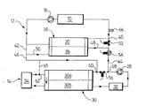
図1と図2に示すように、本発明に係る、自動車エンジン10において発生する熱エネルギーの制御システムは、高温冷却材サイクル12と低温冷却材サイクル14を備えている。この2つの冷却材サイクルは、互いに接続され、同一の冷却材(例えば、水に、エチレングリコールのようなゲル化防止剤を添加したもの)が流通する2つのサイクル構成(高温サイクル構成と低温サイクル構成)を形成しうるようになっている。
As shown in FIGS. 1 and 2, the control system for heat energy generated in the
高温冷却材サイクル12は、冷却材を循環させるためのポンプ(機械式または電動式)16を備えている。また、この高温冷却材サイクル12は、公知の熱エネルギー制御システムと同様に、エンジンの出口部分に、サーモスタットまたは自動温度調節式のバルブ(図示せず)を具備している。なお、これらのサーモスタットまたはバルブは、冷却材の分岐部や、自動車の主たるラジエータである高温用ラジエータ(熱交換器)20に設けることもできる。
The high
高温冷却材サイクル12は、他の熱交換器、例えばオイルクーラを備えることもできる。しかし、このような構成要素は、本発明の技術的範囲とは無関係であるため、図示しない。
The high
低温冷却材サイクル14は、電動式の循環ポンプ28と、低温用ラジエータ30を備えている。低温用ラジエータ30は、第1の通路30aと第2の通路30bを有している。また、低温冷却材サイクル14は、車室用空調サイクルの一部をなすコンデンサ32を備えている。このコンデンサ32は、公知のコンデンサとは対照的に、低温冷却材サイクル14を流れる冷却材によって冷却される。この際、低温ループを流れる冷却材の温度は、コンデンサ32が良好に稼動しうるよう、40〜60℃とすることが必要である。さらに、低温冷却材サイクル14は、この低温冷却材サイクル14を流れる冷却材によって冷却される過給クーラ34も備えている。
The low-
本発明のシステムは、後に詳しく説明するように、高温冷却材サイクル12または低温冷却材サイクル14と接続される切替ラジエータ36を備えている。図1と図2においては、高温用ラジエータ20と切替ラジエータ36は、単一の熱交換器38内で、それぞれ独立のセクションを構成している。しかし、変形例として、切替ラジエータ36は、高温用ラジエータ20および低温用ラジエータ30の双方と別体の装置とすることもできる。
The system of the present invention includes a switching
また、本発明のシステムは、高温冷却材サイクル12を流れる高温の冷却材を、切替ラジエータ36へ送り込むための入口管40と、高温の冷却材を、切替ラジエータ36から高温冷却材サイクル12へ戻すための出口管42を備えている。
In addition, the system of the present invention returns the high temperature coolant flowing through the high
一方、低温冷却材用の入口管44は、低温冷却材サイクル14を流れる冷却材を、切替ラジエータ36へ送り込む役割を果たし、他方、低温冷却材用の出口管46は、冷却材を、切替ラジエータ36から低温冷却材サイクルへ戻す役割を果たす。2つの入口管40,44は、第1の共通管48へ連なっている。また、2つの出口管42,46は、第2の共通管50から分岐している。
On the other hand, the inlet pipe 44 for the low temperature coolant serves to feed the coolant flowing through the low
第1の切替手段としての電動バルブ52は、高温冷却材の入口管40に取り付けられており、他方、第2の切替手段としての電動バルブ54は、低温冷却材の入口管44に取り付けられている。さらに、第3の切替手段としての電動バルブ56は、低温冷却材サイクル14における、入口管44の出口ノード58と、出口管46の入口ノード60との間に取り付けられている。入口ノード60は、冷却材の循環する方向において、低温用ラジエータ30の上流側、より詳しくは、低温用ラジエータ30の第1の通路30aの上流側に位置している。
The
しかし、この実施形態の変形例においては、破線61で示すように、出口管46は、低温用ラジエータ30の第1の通路30aの下流側に位置するノード62において、低温冷却材サイクル14と接続される。
However, in a modification of this embodiment, the
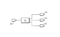
第1、第2および第3の切替手段は、それぞれ、2つの切替位置を有する電動バルブであるが、他の機器とすることもできる。この電動バルブは、全開もしくは全閉という二者択一的な制御も、段階的な制御も可能である。電動バルブは、制御装置64(図3参照)によって制御される。この制御に用いるため、エンジン冷却の際に参照されるべき代表的なパラメータを、センサ66が測定するようになっている。
Each of the first, second, and third switching means is an electric valve having two switching positions, but may be another device. This electric valve can be controlled either in a fully open or fully closed manner, or in a stepwise control. The electric valve is controlled by a control device 64 (see FIG. 3). For use in this control, the
センサ66は、エンジン10の出口における冷却材の温度を測定する。エンジンの出口における冷却材の温度は、上記のパラメータとして最も適している。しかし、エンジン負荷を表すパラメータや、エンジンの負荷状態を知りうるパラメータ(例えばエンジントルク)のような他のパラメータも想定しうる。制御装置64には、電動バルブ52,54,56のいずれを開放して、いずれを閉鎖するかを制御するための制御手順が格納されている。
図1に示す熱エネルギー制御システムは、「低温サイクル構成」をとっており、切替ラジエータ36は、低温冷却材サイクル14と接続されている。すなわち、電動バルブ52,56は閉鎖され、他方、電動バルブ54は開放されている。したがって、切替ラジエータ36は、低温用ラジエータ30の第1および第2の通路30a,30bと直列になっている。
The thermal energy control system shown in FIG. 1 has a “low temperature cycle configuration”, and the switching
出口管46は、第1の通路30aの上流側に位置する入口ノード60において、低温冷却材サイクル14と接続されているが、この出口管46を、第1の通路30aの下流側(ノード62)において接続する場合には、切替ラジエータ36と第1の通路30aは並列となり、電動バルブ56を用いる必要はなくなる。
The
図2に示す熱エネルギー制御システムは、切替ラジエータ36が、高温冷却材サイクルの一部をなす「高温サイクル構成」をとっている。このサイクル構成においては、電動バルブ52,56は開放され、他方、電動バルブ54は閉鎖されている。したがって、高温用ラジエータ20と低温用ラジエータ30は、並列的に働く。この場合、切替ラジエータ36の熱容量が、高温用ラジエータ20のそれに加わる。しかし、低温冷却材サイクル14の熱容量は、低温用ラジエータ30のそれに限定される。
In the thermal energy control system shown in FIG. 2, the switching
図4は、電動バルブ52,54,56を制御する際の手順の一例を示した流れ図である。エンジンの始動時(過程100)には、システムは、低温サイクル構成にあるか否かは不明である(過程102)。一方、エンジンが始動した当初は、冷却材は冷えた状態にあるため、エンジン温度の上昇速度を加速しうるよう、冷却材を再冷却するのは好ましくない。
FIG. 4 is a flowchart showing an example of a procedure for controlling the
過程104においては、センサ66を介して、エンジンの出口における冷却材の温度(Ts mot)データを収集する。
In
過程106においては、収集した冷却材の温度(Ts mot)データを、低温閾値(Ts mot 1;例えば85℃)と比較する。この結果、冷却材の温度が、低温閾値(Ts mot 1)よりも低いときには、過程108において、システムが低温サイクル構成にあるか否かの検証を行う。
In
システムが低温サイクル構成にあるときには、矢印110で示すように、過程102に戻る。 When the system is in the cold cycle configuration, the process returns to step 102 as indicated by arrow 110.
他方、システムが低温サイクル構成にないときには、過程112において、制御装置64は、各電動バルブの開閉を制御して、システムを低温サイクル構成に切り替える。
On the other hand, when the system is not in the low temperature cycle configuration, in
本発明においては、所定の時間tが経過したときに、エンジンの出口における冷却材の温度(Ts mot)が、低温閾値(Ts mot 1)よりも低いと検知されたときには、制御装置64は、電動バルブ52を閉鎖するよう指令を出す。その結果、高温冷却材サイクルを流れる冷却材は、切替ラジエータ36を通過することはできなくなる。
In the present invention, when it is detected that the coolant temperature (Ts mot) at the outlet of the engine is lower than the low temperature threshold (Ts mot 1) when the predetermined time t has elapsed, the control device 64 A command is issued to close the
さらに、所定の遅延時間t1が経過した後、制御装置64は、電動バルブ54の開放を指示する。このため、低温冷却材サイクル14を流れる冷却材の一部は、切替ラジエータ36へ導かれ、他の一部は、開放されたままの電動バルブ56へ向かって循環を続ける。したがって、切替ラジエータ36からは、徐々に、高温の冷却材がなくなり、低温の冷却材がこれに置き換わる。この過程は徐々に進行するため、3つの電動バルブの切替を同時に指示したときとは違って、熱的な衝撃は回避される。
Further, after a predetermined delay time t 1 has elapsed, the
ついで、所定の遅延時間t2が経過した後、制御装置64は、電動バルブ56を閉鎖するよう指令を出す。その結果、これまで低温用ラジエータ30の第1の通路30aへ向かっていた低温の冷却材は、すべて、切替ラジエータ36へ向かう。
Next, after a predetermined delay time t 2 has elapsed, the
こうして、システムは、高温サイクル構成から低温サイクル構成へ完全に切り替わる。 Thus, the system switches completely from the high temperature cycle configuration to the low temperature cycle configuration.
エンジンの出口における冷却材の温度が、低温閾値よりも低い間は、システムは、低温サイクル構成に留まる。 While the coolant temperature at the engine outlet is below the cold threshold, the system remains in the cold cycle configuration.
エンジンの出口における冷却材の温度(Ts mot)が、低温閾値(Ts mot 1)よりも高い場合には、過程114において、この温度(Ts mot)を、高温閾値(Ts mot 2;例えば105℃)と比較する。この比較の結果、エンジンの出口における冷却材の温度(Ts mot)が、低温閾値(Ts mot 1)よりも高いが、高温閾値(Ts mot 2;例えば105℃)よりは低いことが判明した場合には、システムにおける冷却材サイクルの構成は変えられない。換言すれば、システムが低温サイクル構成にあって、冷却材の温度が、低温閾値よりも高いものの、例えば100℃に留まる場合には、この低温サイクル構成を維持する。
If the coolant temperature (Ts mot) at the engine outlet is higher than the low temperature threshold (Ts mot 1), in
他方、過程114において、エンジンの出口における冷却材の温度(Ts mot)が、高温閾値(Ts mot 2)よりも高いことが判明した場合には、制御装置64は、システムを低温サイクル構成から高温サイクル構成へ切り替える。このために、制御装置64は、電動バルブ52,56を開放し、電動バルブ54を閉鎖する。
On the other hand, if it is determined in
過程114においては、各電動バルブの開閉は同時に行われる。すなわち、時間遅延は想定されていない。しかし、変形例として、上記の高温サイクル構成から低温サイクル構成への切替に係るt1,t2のような時間遅延を導入することもできる。この場合、制御装置は、各電動バルブに対して、過程112における順序とは反対の順序で指令を発する。すなわち、最初に電動バルブ56を開放し、ついで電動バルブ54を閉鎖し、最後に電動バルブ52を開放する。この結果、システムは、過程118におけるように、高温サイクル構成となる。
In
エンジンの出口における冷却材の温度(Ts mot)が、高温閾値(Ts mot 2)よりも低下した場合でも、システムは、直ちに低温サイクル構成に戻ることはなく、冷却材の温度が、低温閾値(Ts mot 1)よりも低くなるまでは、システムは、高温サイクル構成に留まる。 Even if the coolant temperature (Ts mot) at the engine outlet drops below the high temperature threshold (Ts mot 2), the system will not immediately return to the low temperature cycle configuration, and the coolant temperature will be reduced to the low temperature threshold ( Until it is lower than Ts mot 1), the system remains in the high temperature cycle configuration.
このように、本発明においては、低温閾値と高温閾値の2つの閾値を設定するため、システムの安定性を保つことができ、かつ高温サイクル構成と低温サイクルの間の切替が不安定になるのを回避することができる。 In this way, in the present invention, since the two threshold values, the low temperature threshold value and the high temperature threshold value, are set, the stability of the system can be maintained, and the switching between the high temperature cycle configuration and the low temperature cycle becomes unstable. Can be avoided.
10 エンジン
12 高温冷却材サイクル
14 低温冷却材サイクル
16 ポンプ
20 高温用ラジエータ
28 循環ポンプ
30 低温用ラジエータ
30a 第1の通路
30b 第2の通路
32 コンデンサ
34 過給クーラ
36 切替ラジエータ
38 熱交換器
40 高温冷却材用の入口管
42 高温冷却材用の出口管
44 低温冷却材用の入口管
46 低温冷却材用の出口管
48 第1の共通管
50 第2の共通管
52,54,56 電動バルブ
58 出口ノード
60 入口ノード
64 制御装置
66 センサ
10 engine
12 High temperature coolant cycle
14 Low temperature coolant cycle
16 pump
20 High temperature radiator
28 Circulation pump
30 Low temperature radiator
30a First passage
30b Second passage
32 capacitors
34 Supercooler
36 switching radiator
38 heat exchanger
40 Inlet pipe for high temperature coolant
42 Outlet pipe for high temperature coolant
44 Inlet pipe for cryogenic coolant
46 Outlet pipe for cryogenic coolant
48 First common pipe
50 Second common pipe
52,54,56 Electric valve
58 Exit node
60 Ingress node
64 control unit
66 sensors
Claims (14)
Applications Claiming Priority (1)
| Application Number | Priority Date | Filing Date | Title |
|---|---|---|---|
| PCT/FR2004/003360 WO2006070080A1 (en) | 2004-12-23 | 2004-12-23 | Thermal energy management system for a vehicle heat engine provided with a time-delay switching means |
Publications (2)
| Publication Number | Publication Date |
|---|---|
| JP2008525701A JP2008525701A (en) | 2008-07-17 |
| JP4503652B2 true JP4503652B2 (en) | 2010-07-14 |
Family
ID=36614542
Family Applications (1)
| Application Number | Title | Priority Date | Filing Date |
|---|---|---|---|
| JP2007547556A Active JP4503652B2 (en) | 2004-12-23 | 2004-12-23 | Automotive engine thermal energy control system with switching means with time delay |
Country Status (4)
| Country | Link |
|---|---|
| EP (1) | EP1828560B1 (en) |
| JP (1) | JP4503652B2 (en) |
| AT (1) | ATE511002T1 (en) |
| WO (1) | WO2006070080A1 (en) |
Families Citing this family (7)
| Publication number | Priority date | Publication date | Assignee | Title |
|---|---|---|---|---|
| DE102010039810A1 (en) * | 2010-08-26 | 2012-03-01 | Behr Gmbh & Co. Kg | Cooling system and cooling method for a vehicle |
| DE102012223069A1 (en) * | 2012-12-13 | 2014-06-18 | Bayerische Motoren Werke Aktiengesellschaft | Coolant circuit for an internal combustion engine |
| KR102152616B1 (en) * | 2014-05-12 | 2020-09-07 | 현대자동차 주식회사 | Cooling system for vehicle |
| KR102152617B1 (en) * | 2014-05-12 | 2020-09-07 | 현대자동차 주식회사 | Cooling system for vehicle |
| KR101575254B1 (en) | 2014-05-20 | 2015-12-07 | 현대자동차 주식회사 | Cooling and thermoelectric power generating system for vehicle |
| US10352230B2 (en) * | 2015-02-06 | 2019-07-16 | Honda Motor Co., Ltd. | Cooling control system for internal combustion engine |
| KR102274020B1 (en) * | 2017-03-13 | 2021-07-06 | 현대자동차 주식회사 | Control system for flowing of coolant |
Family Cites Families (4)
| Publication number | Priority date | Publication date | Assignee | Title |
|---|---|---|---|---|
| JPS6392016U (en) * | 1986-12-08 | 1988-06-14 | ||
| DE9013459U1 (en) * | 1990-09-25 | 1992-01-30 | Robert Bosch Gmbh, 7000 Stuttgart, De | |
| JP3422036B2 (en) * | 1992-07-13 | 2003-06-30 | 株式会社デンソー | Vehicle cooling system |
| FR2832187B1 (en) * | 2001-11-13 | 2005-08-05 | Valeo Thermique Moteur Sa | THERMAL ENERGY MANAGEMENT SYSTEM DEVELOPED BY A MOTOR VEHICLE THERMAL MOTOR |
-
2004
- 2004-12-23 WO PCT/FR2004/003360 patent/WO2006070080A1/en active Application Filing
- 2004-12-23 AT AT04816481T patent/ATE511002T1/en not_active IP Right Cessation
- 2004-12-23 JP JP2007547556A patent/JP4503652B2/en active Active
- 2004-12-23 EP EP04816481A patent/EP1828560B1/en active Active
Also Published As
| Publication number | Publication date |
|---|---|
| JP2008525701A (en) | 2008-07-17 |
| WO2006070080A1 (en) | 2006-07-06 |
| EP1828560B1 (en) | 2011-05-25 |
| ATE511002T1 (en) | 2011-06-15 |
| EP1828560A1 (en) | 2007-09-05 |
Similar Documents
| Publication | Publication Date | Title |
|---|---|---|
| US10125662B2 (en) | Engine cooling device for vehicle | |
| JP3095377B2 (en) | Chiller equipment | |
| US20160082805A1 (en) | R744 based heat pump system with a water cooled gas cooler for cooling, heating and dehumidification of an ev/hev | |
| KR101235039B1 (en) | Heat pump system for vehicle | |
| JPH02185821A (en) | Air conditioner for automobile | |
| JP2011173543A (en) | Battery cooling/heating device | |
| JP7105933B2 (en) | Outdoor unit of refrigerating device and refrigerating device provided with the same | |
| JP6578959B2 (en) | Vehicle coolant heating apparatus and vehicle coolant heating program | |
| CN108136876A (en) | Vehicle temperature adjustment device | |
| JP2006046755A (en) | Air conditioner | |
| JP2010065543A (en) | Vehicular cooling system | |
| JPS6325166B2 (en) | ||
| EP2597400A2 (en) | Heat pump system | |
| JP2020102380A (en) | Temperature control circuit and control method | |
| JP4503652B2 (en) | Automotive engine thermal energy control system with switching means with time delay | |
| US9261297B2 (en) | Cooling device | |
| KR100852344B1 (en) | Air conditioning apparatus | |
| JP4337126B2 (en) | Supercritical heat pump equipment | |
| US8132547B2 (en) | Thermal energy management system for a vehicle heat engine provided with a time-delay switching means | |
| JP2006336949A (en) | Heat storage type air conditioner | |
| JP2000211345A (en) | Vehicle air-conditioner | |
| JP2002364362A (en) | Engine cooling apparatus | |
| JPH0726955A (en) | Oil temperature control device for vehicle | |
| WO2024070421A1 (en) | Heat management system | |
| JP2007327720A (en) | Refrigerating circuit of heat pump |
Legal Events
| Date | Code | Title | Description |
|---|---|---|---|
| TRDD | Decision of grant or rejection written | ||
| A01 | Written decision to grant a patent or to grant a registration (utility model) |
Free format text: JAPANESE INTERMEDIATE CODE: A01 Effective date: 20100330 |
|
| A01 | Written decision to grant a patent or to grant a registration (utility model) |
Free format text: JAPANESE INTERMEDIATE CODE: A01 |
|
| A61 | First payment of annual fees (during grant procedure) |
Free format text: JAPANESE INTERMEDIATE CODE: A61 Effective date: 20100421 |
|
| R150 | Certificate of patent or registration of utility model |
Ref document number: 4503652 Country of ref document: JP Free format text: JAPANESE INTERMEDIATE CODE: R150 Free format text: JAPANESE INTERMEDIATE CODE: R150 |
|
| FPAY | Renewal fee payment (event date is renewal date of database) |
Free format text: PAYMENT UNTIL: 20130430 Year of fee payment: 3 |
|
| FPAY | Renewal fee payment (event date is renewal date of database) |
Free format text: PAYMENT UNTIL: 20140430 Year of fee payment: 4 |
|
| R250 | Receipt of annual fees |
Free format text: JAPANESE INTERMEDIATE CODE: R250 |
|
| R250 | Receipt of annual fees |
Free format text: JAPANESE INTERMEDIATE CODE: R250 |
|
| R250 | Receipt of annual fees |
Free format text: JAPANESE INTERMEDIATE CODE: R250 |
|
| R250 | Receipt of annual fees |
Free format text: JAPANESE INTERMEDIATE CODE: R250 |
|
| R250 | Receipt of annual fees |
Free format text: JAPANESE INTERMEDIATE CODE: R250 |
|
| R250 | Receipt of annual fees |
Free format text: JAPANESE INTERMEDIATE CODE: R250 |
|
| R250 | Receipt of annual fees |
Free format text: JAPANESE INTERMEDIATE CODE: R250 |
|
| R250 | Receipt of annual fees |
Free format text: JAPANESE INTERMEDIATE CODE: R250 |
|
| R250 | Receipt of annual fees |
Free format text: JAPANESE INTERMEDIATE CODE: R250 |
|
| R250 | Receipt of annual fees |
Free format text: JAPANESE INTERMEDIATE CODE: R250 |
|
| R250 | Receipt of annual fees |
Free format text: JAPANESE INTERMEDIATE CODE: R250 |
|
| R250 | Receipt of annual fees |
Free format text: JAPANESE INTERMEDIATE CODE: R250 |