JP4501093B2 - Flip chip mounting apparatus and mounting method - Google Patents
Flip chip mounting apparatus and mounting method Download PDFInfo
- Publication number
- JP4501093B2 JP4501093B2 JP2000213096A JP2000213096A JP4501093B2 JP 4501093 B2 JP4501093 B2 JP 4501093B2 JP 2000213096 A JP2000213096 A JP 2000213096A JP 2000213096 A JP2000213096 A JP 2000213096A JP 4501093 B2 JP4501093 B2 JP 4501093B2
- Authority
- JP
- Japan
- Prior art keywords
- flip chip
- cylinder
- motor
- slider
- package
- Prior art date
- Legal status (The legal status is an assumption and is not a legal conclusion. Google has not performed a legal analysis and makes no representation as to the accuracy of the status listed.)
- Expired - Lifetime
Links
Images

Classifications
-
- H—ELECTRICITY
- H01—ELECTRIC ELEMENTS
- H01L—SEMICONDUCTOR DEVICES NOT COVERED BY CLASS H10
- H01L24/00—Arrangements for connecting or disconnecting semiconductor or solid-state bodies; Methods or apparatus related thereto
- H01L24/74—Apparatus for manufacturing arrangements for connecting or disconnecting semiconductor or solid-state bodies
- H01L24/75—Apparatus for connecting with bump connectors or layer connectors
Landscapes
- Engineering & Computer Science (AREA)
- Manufacturing & Machinery (AREA)
- Computer Hardware Design (AREA)
- Microelectronics & Electronic Packaging (AREA)
- Power Engineering (AREA)
- Wire Bonding (AREA)
- Die Bonding (AREA)
Description
【0001】
【発明の属する技術分野】
本発明は、フリップチップ実装装置及び実装方法に関し、特に、高精度搭載、高精度加圧、低衝撃搭載を行うフリップチップ実装装置及び実装方法に関する。
【0002】
【従来の技術】
従来のフリップチップ実装装置及び実装方法について、図2を参照して説明する。図2は、従来のフリップチップ実装装置の構造を模式的に示す側面図である。図2に示すように、従来のフリップチップ実装装置は、フリップチップを上下に稼働する上下位置制御部と、フリップチップを加圧する加圧部とからなり、上下位置制御部と加圧部との間にはリニアガイド17が設けられ、リニアガイド17に沿って加圧部が上下動する。
【0003】
また、上下位置制御部は、モータ15とモータ15の回転運動をネジによって上下運動に変換するボールネジ16とからなり、加圧部は、フリップチップ11を加圧する加圧シリンダ14と、フリップチップ11のθ方向の位置を制御するθ軸モータ7及びタイミングベルト8と、パッケージ12とフリップチップ11との平行度を維持する球面軸受け9と、フリップチップ11を加熱するヒータ10とにより構成されている。
【0004】
このような構造のフリップチップ実装装置を用いて実装する場合には、まず、フリップチップ11をヒータ10により加熱し、θ軸モータ7及びタイミングベルト8により位置合わせを行った後、モータ15を回転させる。モータ15が回転すると、その回転運動がボールネジ16で上下運動に変換され、この上下運動によって加圧部がリニアガイド17に沿って下降する。そして、フリップチップ11とパッケージ12とを接触させた後、加圧シリンダ14により、フリップチップ11に荷重を負荷することにより、フリップチップ11の実装を行っている。
【0005】
【発明が解決しようとする課題】
しかしながら、このような従来のフリップチップ実装装置では、加圧シリンダ14によりフリップチップ11を加圧する際にリニアガイド17に荷重がかかり、その荷重の大きさによってはリニアガイド17内の軸受けにたわみが発生し、加圧シリンダ14の押圧方向が変化してしまう。そして、この押圧方向の変化により、パッケージ12のフリップチップ搭載面の法線方向と異なる方向に力が作用してしまい、この力によりフリップチップ11に位置ずれが生じてしまうという問題がある。
【0006】
また、従来のフリップチップ実装装置では、ボールネジ16やリニアガイド17等の転がり軸受けを使用するため、フリップチップ11をパッケージ12に接触させる際に、リニアガイド17内のボールの転がりによって摩擦力が発生し、その摩擦力が進行中一定にならないために、接触時の荷重を軽微にすることができず、搭載時の荷重を高精度に制御することができないという問題がある。
【0007】
本発明は、上記問題点に鑑みてなされたものであって、その主たる目的は、フリップチップを加圧する際の位置ずれを防止し、フリップチップを高精度に搭載することができ、また、フリップチップとパッケージ接触時の荷重を軽微にし、搭載時の荷重を高精度に制御することができるフリップチップ実装装置及び実装方法を提供することにある。
【0008】
【課題を解決するための手段】
上記目的を達成するため、本発明は、フリップチップをパッケージに押圧するシリンダと、前記シリンダに接続され前記フリップチップの高さ方向の位置を制御するモータと、前記モータと前記フリップチップとの間に配設されるエアスライダと、前記フリップチップの回転角度を制御するθ軸モータと、前記パッケージを固定するステージとを備えたフリップチップ実装装置であって、前記シリンダと前記モータと前記エアスライダとが前記フリップチップに向かってこの順に直線状に配置され、前記エアスライダが、中心軸方向に上下に滑動する円筒状のスライダシャフトと、前記スライダシャフト内面に当接するベアリングと、前記ベアリングを介して自在に回動するプッシャとを含み、前記エアスライダの前記中心軸と前記シリンダの駆動軸とが相重なり、前記プッシャを押し下げるものである。
【0010】
また、本発明においては、前記フリップチップの高さ方向の位置を制御する前記モータが、VCMからなることが好ましい。
【0011】
また、本発明のフリップチップ実装方法は、フリップチップをパッケージに押圧するシリンダと、前記シリンダに接続され前記フリップチップの高さ方向の位置を制御するモータと、前記モータと前記フリップチップとの間に配設されるエアスライダと、前記フリップチップの回転角度を制御するθ軸モータと、前記パッケージを固定するステージとを備え、前記シリンダと前記モータと前記エアスライダとが前記フリップチップに向かってこの順に直線状に配置されたフリップチップ実装装置を用いたフリップチップ実装方法であって、前記エアスライダが、中心軸方向に上下に滑動する円筒状のスライダシャフトと、前記スライダシャフト内面に当接するベアリングと、前記ベアリングを介して自在に回動するプッシャとを含み、前記エアスライダの前記中心軸と前記シリンダの駆動軸とが相重なり、前記プッシャを押し下げるように前記シリンダを駆動し、前記シリンダと前記モータと前記エアスライダとの配列方向に、前記フリップチップを押圧するものである。
【0012】
このように、本発明は加圧するシリンダと他の機構部品が同一直線状に配置されているためにフリップチップを高い位置精度でパッケージに搭載することができ、また、エアスライダによりフリップチップ接触時の荷重を軽微にすることができ、搭載時の荷重を高精度に制御することができる。
【0013】
【発明の実施の形態】
本発明に係るフリップチップ実装装置は、その好ましい一実施の形態において、フリップチップ11をパッケージ12に押圧する低摩擦シリンダ1と、フリップチップの高さ方向の位置を制御するVCM2と、フリップチップに加わる荷重の制御を行うエアスライダ3と、フリップチップのθ方向の位置を制御するθ軸モータ7及びタイミングベルト8と、パッケージとフリップチップとの平行度を保持する球面軸受け9と、フリップチップを加熱するヒータ10とを備え、低摩擦シリンダ1とVCM2とエアスライダ3とが直線状に配置され、かつ、エアスライダ3の中心軸と低摩擦シリンダ1の駆動軸とを相重なるように配置することにより、フリップチップに衝撃を与えることなく、高い位置精度でパッケージに搭載するものである。
【0014】
【実施例】
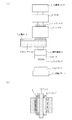
上記した本発明の実施の形態についてさらに詳細に説明すべく、本発明の一実施例について図1を参照して説明する。図1は、本発明の一実施例に係るフリップチップ実装装置の構造を模式的に示す図であり、(a)は側面図、(b)はエアスライダの拡大断面図である。
【0015】
図1を参照すると、本実施例のフリップチップ実装装置は、フリップチップを加圧するための低摩擦シリンダ1と、低摩擦シリンダ1の駆動軸上に配置され、高さ位置の制御及び低荷重搭載を実現するVCM(ボイスコイルモータ)2と、同じく低摩擦シリンダ1の駆動軸上に配置され、荷重制御を高精度で行うためのエアスライダ3と、θ方向の位置制御を行うθ軸モータ7及びタイミングベルト8と、フリップチップ11の搭載面が自在に可動し、パッケージ12とフリップチップ11との平行度を維持する球面軸受け9と、フリップチップ11を加熱するヒータ10と、フリップチップ11と、搭載パッケージ12と、搭載パッケージを固定する搭載ステージ13とから構成されている。
【0016】
また、エアスライダ3は、図1(b)に示すように、エアスライダ3内を上下に滑動する中空形状のスライダシャフト4と、スライダシャフト4内に配置されるベアリング6と、スライダシャフト4内部にベアリング6を介して回動可能に配設されるプッシャ5とにより構成される。
【0017】
このようなフリップチップ実装装置を用いて実装する場合には、まず、フリップチップ11をヒータ10により加熱し、θ軸モータ7及びタイミングベルト8によりθ方向の位置合わせを行う。次に、VCM2を駆動させてエアスライダ3内のプッシャ5を押し下げてフリップチップ11を下降させ、パッケージ12にフリップチップ11を搭載する。このとき、VCM2は最初は高速で動かし、パッケージ12とフリップチップ11が接触する直前に低速で移動させることにより、接触時の衝撃を緩和することができる。
【0018】
ここで、VCM2及びエアスライダ3は非接触運動を行うために摩擦力はきわめて小さく、また転がり摩擦による摩擦変動もないことから、低速度運動を安定して行うことができる。従って、パッケージ12とフリップチップ11とを衝撃を加えることなく接触させることが可能となる。さらに、球面軸受け9を接触時に自由な状態にしておくためフリップチップ11の下面とパッケージ12の上面が互いに平行になるように接触させることができる。
【0019】
次に、フリップチップ11を加圧するために、低摩擦シリンダ1に圧縮空気を送り込む。この時、低摩擦シリンダ1の加圧位置と、上下方向移動のためのVCM2およびエアスライダ3は低摩擦シリンダ1の駆動軸上に直線状に配置されているために、フリップチップ11に押圧方向と異なる方向成分の荷重が負荷されることはなく、加圧時にフリップチップ11の位置ずれが生じることを防止することができる。
【0020】
また、自在に可動する球面軸受け9の働きによって、フリップチップ11の下面とパッケージ12の上面を互いに平行に保つことができるため、フリップチップ11に搭載面の法線方向のみから加重を負荷することができる。従って、加圧時にフリップチップ11が加圧方向と垂直な方向に変動することを防ぐことができる。
【0021】
また、シリンダ1として低摩擦のシリンダを用いているため、シリンダ内の摩擦力を小さくすることができ、また、エアスライダ3の摩擦力が極小であるため、加圧力を空気圧力に正確に対応させることができ、フリップチップ11を高精度に加圧することが可能になる。
【0022】
さらに、フリップチップ11加圧時に、スライダシャフト4内のプッシャ5を加圧しているため、セラミック等で構成されるエアスライダ3とスライダシャフト4に負荷を直接かけることがないため、エアスライダ3とスライダシャフト4の破壊を防止することができる。
【0023】
【発明の効果】
以上説明したように、本発明のフリップチップ実装装置によれば下記記載の効果を奏する。
【0024】
第1の効果はフリップチップを高い位置精度でパッケージに搭載することができるということである。
【0025】
その理由は、加圧するシリンダとVCMやエアシリンダ等の他の機構部品とが同一直線状に配置され、およびフリップチップとパッケージの表面が互いに平行に保持される球面軸受けを使用しているため、フリップチップに横方向の荷重が負荷されることがなく、加圧時に位置ずれが発生しないからである。
【0026】
また、第2の効果は、フリップチップ接触時の荷重を軽微にすることができ、搭載時の荷重を高精度に制御することができるということである。
【0027】
その理由は、低摩擦のシリンダ、VCMやエアスライダを使用することにより、シリンダに印加する圧力を正確にフリップチップに伝達することができるからである。
【図面の簡単な説明】
【図1】本発明の一実施例に係るフリップチップ実装装置の構造を模式的に示す図であり、(a)は側面図、(b)はエアスライダの拡大断面図である。
【図2】従来のフリップチップ実装装置の構造を模式的に示す側面図である。
【符号の説明】
1 低摩擦シリンダ
2 VCM
3 エアスライダ
4 スライダシャフト
5 プッシャ
6 ベアリング
7 θ軸モータ
8 タイミングベルト
9 球面軸受け
10 ヒータ
11 フリップチップ
12 パッケージ
13 搭載ステージ
14 加圧シリンダ
15 モータ
16 ボールネジ
17 リニアガイド[0001]
BACKGROUND OF THE INVENTION
The present invention relates to a flip-chip mounting apparatus and mounting method, and more particularly to a flip-chip mounting apparatus and mounting method for performing high-precision mounting, high-precision pressurization, and low-impact mounting.
[0002]
[Prior art]
A conventional flip chip mounting apparatus and mounting method will be described with reference to FIG. FIG. 2 is a side view schematically showing the structure of a conventional flip chip mounting apparatus. As shown in FIG. 2, the conventional flip chip mounting apparatus includes a vertical position control unit that moves the flip chip up and down and a pressure unit that pressurizes the flip chip, and includes a vertical position control unit and a pressure unit. A linear guide 17 is provided between them, and the pressure unit moves up and down along the linear guide 17.
[0003]
The vertical position control unit includes a motor 15 and a ball screw 16 that converts the rotational motion of the motor 15 into vertical motion using a screw. The pressure unit includes a pressure cylinder 14 that pressurizes the flip chip 11, and the flip chip 11. The θ-axis motor 7 and the timing belt 8 for controlling the position in the θ-direction of the motor, the spherical bearing 9 for maintaining the parallelism between the package 12 and the flip chip 11, and the
[0004]
When mounting using the flip chip mounting apparatus having such a structure, first, the flip chip 11 is heated by the
[0005]
[Problems to be solved by the invention]
However, in such a conventional flip chip mounting apparatus, a load is applied to the linear guide 17 when the flip chip 11 is pressed by the pressure cylinder 14, and depending on the magnitude of the load, the bearing in the linear guide 17 may bend. Occurs, and the pressing direction of the pressure cylinder 14 changes. Due to this change in the pressing direction, a force acts in a direction different from the normal direction of the flip chip mounting surface of the package 12, and there is a problem that the flip chip 11 is displaced due to this force.
[0006]
Further, since the conventional flip chip mounting apparatus uses rolling bearings such as the ball screw 16 and the linear guide 17, when the flip chip 11 is brought into contact with the package 12, a frictional force is generated by the rolling of the ball in the linear guide 17. However, since the frictional force does not become constant during the progress, there is a problem that the load at the time of contact cannot be made light and the load at the time of mounting cannot be controlled with high accuracy.
[0007]
The present invention has been made in view of the above-mentioned problems, and its main purpose is to prevent misalignment when pressing the flip chip, and to mount the flip chip with high accuracy. An object of the present invention is to provide a flip chip mounting apparatus and a mounting method capable of reducing the load at the time of contact between the chip and the package and controlling the load at the time of mounting with high accuracy.
[0008]
[Means for Solving the Problems]
In order to achieve the above object, the present invention provides a cylinder that presses a flip chip against a package, a motor that is connected to the cylinder and controls a position in the height direction of the flip chip, and between the motor and the flip chip. A flip chip mounting apparatus comprising: an air slider disposed on the substrate; a θ-axis motor that controls the rotation angle of the flip chip; and a stage that fixes the package. The cylinder, the motor, and the air slider Are arranged linearly in this order toward the flip chip, and the air slider slides up and down in the direction of the central axis, a bearing abutting against the inner surface of the slider shaft, and the bearing. And a pusher that freely rotates, and the central axis of the air slider and the cylinder A drive shaft overlap phase, is shall depressing the pusher.
[0010]
In the present invention, it is preferable that the motor that controls the position of the flip chip in the height direction is a VCM.
[0011]
The flip chip mounting method of the present invention includes a cylinder that presses the flip chip against a package, a motor that is connected to the cylinder and controls a position in the height direction of the flip chip, and between the motor and the flip chip. An air slider, a θ-axis motor that controls the rotation angle of the flip chip, and a stage that fixes the package, and the cylinder, the motor, and the air slider are directed toward the flip chip. A flip-chip mounting method using a flip-chip mounting apparatus arranged in a straight line in this order , wherein the air slider abuts on a cylindrical slider shaft that slides up and down in a central axis direction, and an inner surface of the slider shaft. A bearing and a pusher that freely rotates via the bearing, The central axis of the slider and the drive shaft of the cylinder overlap phase, the drives the cylinder to depress the pusher, the arrangement direction of said cylinder and said motor and said air slider, which presses the flip chip It is.
[0012]
As described above, in the present invention, since the cylinder to be pressurized and the other mechanical parts are arranged in the same straight line, the flip chip can be mounted on the package with high positional accuracy, and when the flip chip is brought into contact with the air slider. The load at the time of mounting can be made light, and the load at the time of mounting can be controlled with high accuracy.
[0013]
DETAILED DESCRIPTION OF THE INVENTION
In a preferred embodiment of the flip chip mounting apparatus according to the present invention, the low friction cylinder 1 that presses the flip chip 11 against the package 12, the
[0014]
【Example】
In order to describe the above-described embodiment of the present invention in more detail, an example of the present invention will be described with reference to FIG. 1A and 1B are diagrams schematically showing a structure of a flip chip mounting apparatus according to an embodiment of the present invention, in which FIG. 1A is a side view and FIG. 1B is an enlarged sectional view of an air slider.
[0015]
Referring to FIG. 1, the flip chip mounting apparatus of the present embodiment is disposed on a low friction cylinder 1 for pressurizing the flip chip and a drive shaft of the low friction cylinder 1, and controls the height position and mounts a low load. VCM (voice coil motor) 2 that realizes the same, an air slider 3 that is disposed on the drive shaft of the low-friction cylinder 1 and performs load control with high accuracy, and a θ-axis motor 7 that performs position control in the θ direction. And the timing belt 8, the mounting surface of the flip chip 11 is freely movable, the spherical bearing 9 that maintains the parallelism between the package 12 and the flip chip 11, the
[0016]
Further, as shown in FIG. 1B, the air slider 3 includes a hollow slider shaft 4 that slides up and down in the air slider 3, a bearing 6 disposed in the slider shaft 4, and an inner portion of the slider shaft 4. And a pusher 5 rotatably disposed via a bearing 6.
[0017]
When mounting using such a flip chip mounting apparatus, first, the flip chip 11 is heated by the
[0018]
Here, since the
[0019]
Next, compressed air is fed into the low friction cylinder 1 to pressurize the flip chip 11. At this time, the pressing position of the low friction cylinder 1 and the
[0020]
Further, since the spherical bearing 9 that can move freely can keep the lower surface of the flip chip 11 and the upper surface of the package 12 parallel to each other, a load is applied to the flip chip 11 only from the normal direction of the mounting surface. Can do. Therefore, it is possible to prevent the flip chip 11 from changing in a direction perpendicular to the pressing direction during pressing.
[0021]
Further, since a low friction cylinder is used as the cylinder 1, the frictional force in the cylinder can be reduced, and the frictional force of the air slider 3 is minimal, so that the applied pressure can be accurately matched to the air pressure. Therefore, it is possible to pressurize the flip chip 11 with high accuracy.
[0022]
Further, since the pusher 5 in the slider shaft 4 is pressurized when the flip chip 11 is pressed, a load is not directly applied to the air slider 3 and the slider shaft 4 made of ceramic or the like. Breakage of the slider shaft 4 can be prevented.
[0023]
【The invention's effect】
As described above, the flip chip mounting apparatus of the present invention has the following effects.
[0024]
The first effect is that the flip chip can be mounted on the package with high positional accuracy.
[0025]
The reason is that a cylinder to be pressurized and other mechanical parts such as a VCM and an air cylinder are arranged in the same straight line, and a spherical bearing in which the flip chip and the surface of the package are held parallel to each other is used. This is because a lateral load is not applied to the flip chip, and no displacement occurs during pressurization.
[0026]
The second effect is that the load at the time of flip chip contact can be made light and the load at the time of mounting can be controlled with high accuracy.
[0027]
The reason is that the pressure applied to the cylinder can be accurately transmitted to the flip chip by using a low friction cylinder, VCM or air slider.
[Brief description of the drawings]
1A and 1B are views schematically showing a structure of a flip chip mounting apparatus according to an embodiment of the present invention, in which FIG. 1A is a side view and FIG. 1B is an enlarged sectional view of an air slider;
FIG. 2 is a side view schematically showing the structure of a conventional flip chip mounting apparatus.
[Explanation of symbols]
1
3 Air slider 4 Slider shaft 5 Pusher 6 Bearing 7 θ axis motor 8 Timing belt 9 Spherical bearing 10 Heater 11 Flip chip 12 Package 13 Mounting stage 14 Pressure cylinder 15 Motor 16 Ball screw 17 Linear guide
Claims (4)
前記シリンダと前記モータと前記エアスライダとが前記フリップチップに向かってこの順に直線状に配置され、
前記エアスライダが、中心軸方向に上下に滑動する円筒状のスライダシャフトと、前記スライダシャフト内面に当接するベアリングと、前記ベアリングを介して自在に回動するプッシャとを含み、前記エアスライダの前記中心軸と前記シリンダの駆動軸とが相重なり、前記プッシャを押し下げることを特徴とするフリップチップ実装装置。 A cylinder that presses the flip chip against the package, a motor that is connected to the cylinder and controls a position in the height direction of the flip chip, an air slider disposed between the motor and the flip chip, and the flip A flip chip mounting apparatus comprising a θ-axis motor for controlling a rotation angle of a chip and a stage for fixing the package,
The cylinder , the motor, and the air slider are linearly arranged in this order toward the flip chip ,
The air slider includes a cylindrical slider shaft that slides up and down in a central axis direction, a bearing that contacts the inner surface of the slider shaft, and a pusher that freely rotates via the bearing, center axis and the drive shaft overlap phase of the cylinder, the flip chip mounting apparatus according to claim Rukoto depressing the pusher.
前記エアスライダが、中心軸方向に上下に滑動する円筒状のスライダシャフトと、前記スライダシャフト内面に当接するベアリングと、前記ベアリングを介して自在に回動するプッシャとを含み、前記エアスライダの前記中心軸と前記シリンダの駆動軸とが相重なり、前記プッシャを押し下げるように前記シリンダを駆動し、
前記シリンダと前記モータと前記エアスライダとの配列方向に、前記フリップチップを押圧することを特徴とするフリップチップ実装方法。 A cylinder that presses the flip chip against the package, a motor that is connected to the cylinder and controls a position in the height direction of the flip chip, an air slider disposed between the motor and the flip chip, and the flip Flip chip mounting comprising a θ-axis motor for controlling the rotation angle of the chip and a stage for fixing the package, wherein the cylinder, the motor, and the air slider are linearly arranged in this order toward the flip chip. A flip chip mounting method using an apparatus,
The air slider includes a cylindrical slider shaft that slides up and down in a central axis direction, a bearing that contacts the inner surface of the slider shaft, and a pusher that freely rotates via the bearing, The center axis and the drive shaft of the cylinder overlap, and the cylinder is driven to push down the pusher,
A flip chip mounting method , wherein the flip chip is pressed in an arrangement direction of the cylinder, the motor, and the air slider .
Priority Applications (1)
| Application Number | Priority Date | Filing Date | Title |
|---|---|---|---|
| JP2000213096A JP4501093B2 (en) | 2000-07-13 | 2000-07-13 | Flip chip mounting apparatus and mounting method |
Applications Claiming Priority (1)
| Application Number | Priority Date | Filing Date | Title |
|---|---|---|---|
| JP2000213096A JP4501093B2 (en) | 2000-07-13 | 2000-07-13 | Flip chip mounting apparatus and mounting method |
Publications (3)
| Publication Number | Publication Date |
|---|---|
| JP2002033338A JP2002033338A (en) | 2002-01-31 |
| JP2002033338A5 JP2002033338A5 (en) | 2007-06-14 |
| JP4501093B2 true JP4501093B2 (en) | 2010-07-14 |
Family
ID=18708907
Family Applications (1)
| Application Number | Title | Priority Date | Filing Date |
|---|---|---|---|
| JP2000213096A Expired - Lifetime JP4501093B2 (en) | 2000-07-13 | 2000-07-13 | Flip chip mounting apparatus and mounting method |
Country Status (1)
| Country | Link |
|---|---|
| JP (1) | JP4501093B2 (en) |
Family Cites Families (6)
| Publication number | Priority date | Publication date | Assignee | Title |
|---|---|---|---|---|
| JP3220483B2 (en) * | 1991-09-12 | 2001-10-22 | 松下電器産業株式会社 | Bonding equipment |
| JPH07221138A (en) * | 1994-02-07 | 1995-08-18 | Fujitsu Ltd | Bonding apparatus and bonding method |
| JP3262683B2 (en) * | 1995-01-20 | 2002-03-04 | 松下電器産業株式会社 | Semiconductor mounting equipment |
| JPH10340931A (en) * | 1997-06-05 | 1998-12-22 | Toray Eng Co Ltd | Chip bonding tool |
| JP3497078B2 (en) * | 1998-03-31 | 2004-02-16 | 株式会社日立ハイテクインスツルメンツ | Die bonder |
| JP3328878B2 (en) * | 1998-10-26 | 2002-09-30 | 澁谷工業株式会社 | Bonding equipment |
-
2000
- 2000-07-13 JP JP2000213096A patent/JP4501093B2/en not_active Expired - Lifetime
Also Published As
| Publication number | Publication date |
|---|---|
| JP2002033338A (en) | 2002-01-31 |
Similar Documents
| Publication | Publication Date | Title |
|---|---|---|
| JP5828943B1 (en) | Electronic component mounting equipment | |
| JP3817207B2 (en) | Mounting processing device and control device for mounting processing device | |
| JPH11168111A (en) | Semiconductor mounting device for coating board with adhesive | |
| JP2009027105A (en) | Bonding device | |
| JP5009738B2 (en) | Pressurizing device and pressurizing method | |
| JP4501093B2 (en) | Flip chip mounting apparatus and mounting method | |
| JP3961162B2 (en) | Electronic component mounting apparatus and electronic component mounting method | |
| JP5026151B2 (en) | Adhesive applicator | |
| JP2002043336A (en) | Electronic component crimping machine | |
| JP2002043797A (en) | Electronic parts mounting device | |
| JP3856375B2 (en) | Mounting apparatus and control method thereof | |
| KR200345187Y1 (en) | A brush machine | |
| JP4197171B2 (en) | Electronic component mounting machine | |
| JP4691923B2 (en) | Equipment for mounting semiconductor devices | |
| JPH09148790A (en) | Electronic device mounter | |
| JP3617957B2 (en) | Rotating reciprocating motion transmission mechanism and processing apparatus using the same | |
| JP3409725B2 (en) | Bonding equipment | |
| JP4381846B2 (en) | Component mounting equipment | |
| JP3640679B2 (en) | IC inspection robot and IC inspection method | |
| JPS62159088A (en) | Moving stage device | |
| JP2009147132A (en) | Chip component mounting device | |
| JP2002057170A (en) | Guide mechanism for electronic component mounting head and electronic component mounting device using that | |
| KR102325662B1 (en) | Laser bonder device pressing system of flexible display device heat process system | |
| JP4034179B2 (en) | Stage and electron microscope apparatus using the same | |
| JP2006114557A (en) | X-y moving table and electronic component bonding device equipped therewith |
Legal Events
| Date | Code | Title | Description |
|---|---|---|---|
| A521 | Request for written amendment filed |
Free format text: JAPANESE INTERMEDIATE CODE: A523 Effective date: 20070426 |
|
| A621 | Written request for application examination |
Free format text: JAPANESE INTERMEDIATE CODE: A621 Effective date: 20070611 |
|
| A977 | Report on retrieval |
Free format text: JAPANESE INTERMEDIATE CODE: A971007 Effective date: 20090528 |
|
| A131 | Notification of reasons for refusal |
Free format text: JAPANESE INTERMEDIATE CODE: A131 Effective date: 20090603 |
|
| A521 | Request for written amendment filed |
Free format text: JAPANESE INTERMEDIATE CODE: A523 Effective date: 20090731 |
|
| TRDD | Decision of grant or rejection written | ||
| A01 | Written decision to grant a patent or to grant a registration (utility model) |
Free format text: JAPANESE INTERMEDIATE CODE: A01 Effective date: 20100326 |
|
| A01 | Written decision to grant a patent or to grant a registration (utility model) |
Free format text: JAPANESE INTERMEDIATE CODE: A01 |
|
| A61 | First payment of annual fees (during grant procedure) |
Free format text: JAPANESE INTERMEDIATE CODE: A61 Effective date: 20100408 |
|
| R150 | Certificate of patent or registration of utility model |
Free format text: JAPANESE INTERMEDIATE CODE: R150 Ref document number: 4501093 Country of ref document: JP Free format text: JAPANESE INTERMEDIATE CODE: R150 |
|
| FPAY | Renewal fee payment (event date is renewal date of database) |
Free format text: PAYMENT UNTIL: 20130430 Year of fee payment: 3 |
|
| FPAY | Renewal fee payment (event date is renewal date of database) |
Free format text: PAYMENT UNTIL: 20130430 Year of fee payment: 3 |
|
| FPAY | Renewal fee payment (event date is renewal date of database) |
Free format text: PAYMENT UNTIL: 20140430 Year of fee payment: 4 |
|
| EXPY | Cancellation because of completion of term |