JP4499747B2 - タービン翼およびそのタービン翼を備えたガスタービン - Google Patents
タービン翼およびそのタービン翼を備えたガスタービン Download PDFInfo
- Publication number
- JP4499747B2 JP4499747B2 JP2006548254A JP2006548254A JP4499747B2 JP 4499747 B2 JP4499747 B2 JP 4499747B2 JP 2006548254 A JP2006548254 A JP 2006548254A JP 2006548254 A JP2006548254 A JP 2006548254A JP 4499747 B2 JP4499747 B2 JP 4499747B2
- Authority
- JP
- Japan
- Prior art keywords
- blade
- turbine
- steel plate
- turbine blade
- plate portion
- Prior art date
- Legal status (The legal status is an assumption and is not a legal conclusion. Google has not performed a legal analysis and makes no representation as to the accuracy of the status listed.)
- Expired - Fee Related
Links
- 229910000831 Steel Inorganic materials 0.000 claims description 93
- 239000010959 steel Substances 0.000 claims description 93
- NJPPVKZQTLUDBO-UHFFFAOYSA-N novaluron Chemical compound C1=C(Cl)C(OC(F)(F)C(OC(F)(F)F)F)=CC=C1NC(=O)NC(=O)C1=C(F)C=CC=C1F NJPPVKZQTLUDBO-UHFFFAOYSA-N 0.000 claims description 64
- 238000007789 sealing Methods 0.000 claims description 18
- 239000002826 coolant Substances 0.000 claims description 9
- 239000002184 metal Substances 0.000 abstract 1
- 239000007789 gas Substances 0.000 description 25
- 238000001816 cooling Methods 0.000 description 17
- 239000000567 combustion gas Substances 0.000 description 16
- 230000003405 preventing effect Effects 0.000 description 4
- 230000002093 peripheral effect Effects 0.000 description 3
- 230000002265 prevention Effects 0.000 description 3
- 229910000639 Spring steel Inorganic materials 0.000 description 2
- 230000006835 compression Effects 0.000 description 2
- 238000007906 compression Methods 0.000 description 2
- 230000001419 dependent effect Effects 0.000 description 2
- 238000010348 incorporation Methods 0.000 description 2
- 230000015572 biosynthetic process Effects 0.000 description 1
- 238000005219 brazing Methods 0.000 description 1
- 238000000034 method Methods 0.000 description 1
- 238000003825 pressing Methods 0.000 description 1
- 238000003466 welding Methods 0.000 description 1
Images
Classifications
-
- F—MECHANICAL ENGINEERING; LIGHTING; HEATING; WEAPONS; BLASTING
- F01—MACHINES OR ENGINES IN GENERAL; ENGINE PLANTS IN GENERAL; STEAM ENGINES
- F01D—NON-POSITIVE DISPLACEMENT MACHINES OR ENGINES, e.g. STEAM TURBINES
- F01D5/00—Blades; Blade-carrying members; Heating, heat-insulating, cooling or antivibration means on the blades or the members
- F01D5/12—Blades
- F01D5/22—Blade-to-blade connections, e.g. for damping vibrations
-
- F—MECHANICAL ENGINEERING; LIGHTING; HEATING; WEAPONS; BLASTING
- F01—MACHINES OR ENGINES IN GENERAL; ENGINE PLANTS IN GENERAL; STEAM ENGINES
- F01D—NON-POSITIVE DISPLACEMENT MACHINES OR ENGINES, e.g. STEAM TURBINES
- F01D11/00—Preventing or minimising internal leakage of working-fluid, e.g. between stages
- F01D11/005—Sealing means between non relatively rotating elements
- F01D11/006—Sealing the gap between rotor blades or blades and rotor
- F01D11/008—Sealing the gap between rotor blades or blades and rotor by spacer elements between the blades, e.g. independent interblade platforms
-
- F—MECHANICAL ENGINEERING; LIGHTING; HEATING; WEAPONS; BLASTING
- F05—INDEXING SCHEMES RELATING TO ENGINES OR PUMPS IN VARIOUS SUBCLASSES OF CLASSES F01-F04
- F05D—INDEXING SCHEME FOR ASPECTS RELATING TO NON-POSITIVE-DISPLACEMENT MACHINES OR ENGINES, GAS-TURBINES OR JET-PROPULSION PLANTS
- F05D2240/00—Components
- F05D2240/80—Platforms for stationary or moving blades
Landscapes
- Engineering & Computer Science (AREA)
- Mechanical Engineering (AREA)
- General Engineering & Computer Science (AREA)
- Turbine Rotor Nozzle Sealing (AREA)
- Control Of Turbines (AREA)
- Engine Equipment That Uses Special Cycles (AREA)
Description
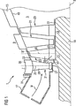
3 軸線
5 流路
7 第1静翼段
9 第2静翼段
11 第1動翼段
13 第2動翼段
63 第1タービン翼
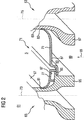
65 第2タービン翼
67 羽根部
69 羽根部
71 台座
73 翼軸線
75 翼軸線
77 第2ばね弾性鋼板部
79 第1ばね弾性鋼板部
87 境界部
Claims (15)
- 翼軸線(73、75)に沿って配置された羽根部(67、69)と、該羽根部(67、69)の脚に配置され翼軸線(73、75)に対して横に延びる台座(71)を有する翼台座部(61)とを備えたタービン翼(63、65)において、台座(71)が、羽根部(67、69)に固定の第1ばね弾性鋼板部(79)によって少なくとも部分的に形成され、該鋼板部(79)が隣接するタービン翼(63、65)に当てられることを特徴とするタービン翼(63、65)。
- 台座(71)が、羽根部(69)の片側面に在る第1突き合わせ部(83)に固定の第1ばね弾性鋼板部(79)と、羽根部(67)の反対側面に在る第2突き合わせ部(81)に固定の第2の鋼板部(77)とによって形成されていることを特徴とする請求項1記載のタービン翼(63、65)。
- 前記第1突き合わせ部(83)および第2突き合わせ部(81)の各突き合わせ部(81、83)が溝あるいは縁の形に形成されていることを特徴とする請求項2記載のタービン翼(63、65)。
- 前記第1ばね弾性鋼板部(79)が、隣接するタービン翼(63、65)に配置された前記第1および第2突き合わせ部とは異なる別の第3突き合わせ部(85)に気密に当てられることを特徴とする請求項3記載のタービン翼(63、65)。
- 前記第3突き合わせ部(85)が支え台の形に形成されていることを特徴とする請求項4記載のタービン翼(63、65)。
- 前記第1ばね弾性鋼板部(79)が、タービン翼(63、65)の休止状態において前記第3突き合わせ部(85)にゆるく接していることを特徴とする請求項4または5に記載のタービン翼(63、65)。
- 前記第1ばね弾性鋼板部(79)が、自己発生バイアス圧のもとで前記第3突き合わせ部(85)に接していることを特徴とする請求項4または5に記載のタービン翼(63、65)。
- 翼台座部(61)が荷重支持構造物として翼脚(35、47)を有していることを特徴とする請求項1ないし7のいずれか1つに記載のタービン翼(63、65)。
- 軸線(3)に沿って延びる断面環状の作動媒体(M)用流路(5)と、軸線(3)に沿って第1翼段(7、11)の後方に配置された第2翼段(9、13)とを備え、それらの各翼段(7、9、11、13)が、環状に配置され半径方向に流路(5)の中に延びる請求項4ないし8のいずれか1つに記載の多数のタービン翼(63、65)を有していることを特徴とするガスタービン(1)。
- タービンロータ(19)における動翼(23)の形をしたタービン翼(63、65)の回転運転中、その回転によって脚から羽根部の方向(99)に作用する遠心力が発生し、前記第1ばね弾性鋼板部(79)が遠心力によって前記第3突き合わせ部(85)に向けて押し付けられ、これによって、遠心力固着で接していることを特徴とする請求項9記載のガスタービン(1)。
- タービン車室(15)における静翼(21)の形をしたタービン翼(63、65)の運転中、冷却材によって圧力勾配が、羽根部の脚から羽根部の方向(99)に向けて発生し、前記第1ばね弾性鋼板部(79)がその圧力勾配によって前記第3突き合わせ部(85)に向けて押し付けられ、これによって、圧縮固着で接していることを特徴とする請求項9記載のガスタービン(1)。
- 第1ばね弾性鋼板部(79)が、ガスタービン(1)におけるタービン翼(63、65)の運転中、シール要素の機能を有していることを特徴とする請求項9ないし11のいずれか1つに記載のガスタービン(1)。
- 同じ翼段(7、9、11、13)の第1タービン翼(63)と隣接する第2タービン翼(65)との間において、第1タービン翼(63)の第1ばね弾性鋼板部(79)および第2タービン翼(65)の第2鋼板部(77)によって、流路(5)の連続した境界部が形成されていることを特徴とする請求項9ないし12のいずれか1つに記載のガスタービン(1)。
- 第1翼段(7、11)の第1タービン翼(63)と軸方向において第1タービン翼(63)に隣接する第2翼段(9、13)の第2タービン翼(65)との間において、第1タービン翼(63)の第1ばね弾性鋼板部(79)と第2タービン翼(65)の第2鋼板部(77)によって、流路(5)の連続した境界部(87)が形成されていることを特徴とする請求項9ないし12のいずれか1つに記載のガスタービン(1)。
- 第1タービン翼(63)に配置された第1ばね弾性鋼板部(79)および第2タービン翼(65)に配置された第2鋼板部(77)が共に、両タービン翼(63、65)のいずれか一方に存在の前記第3突き合わせ部(85)に保持されていることを特徴とする請求項9ないし13のいずれか1つに記載のガスタービン(1)。
Applications Claiming Priority (2)
| Application Number | Priority Date | Filing Date | Title |
|---|---|---|---|
| EP04001107A EP1557534A1 (de) | 2004-01-20 | 2004-01-20 | Turbinenschaufel und Gasturbine mit einer solchen Turbinenschaufel |
| PCT/EP2005/000223 WO2005068785A1 (de) | 2004-01-20 | 2005-01-12 | Turbinenschaufel und gasturbine mit einer solchen turbinenschaufel |
Publications (2)
| Publication Number | Publication Date |
|---|---|
| JP2007518917A JP2007518917A (ja) | 2007-07-12 |
| JP4499747B2 true JP4499747B2 (ja) | 2010-07-07 |
Family
ID=34626466
Family Applications (1)
| Application Number | Title | Priority Date | Filing Date |
|---|---|---|---|
| JP2006548254A Expired - Fee Related JP4499747B2 (ja) | 2004-01-20 | 2005-01-12 | タービン翼およびそのタービン翼を備えたガスタービン |
Country Status (9)
| Country | Link |
|---|---|
| US (2) | US7607889B2 (ja) |
| EP (2) | EP1557534A1 (ja) |
| JP (1) | JP4499747B2 (ja) |
| CN (1) | CN100400795C (ja) |
| AT (1) | ATE520862T1 (ja) |
| ES (1) | ES2370644T3 (ja) |
| PL (1) | PL1706593T3 (ja) |
| RU (1) | RU2332575C2 (ja) |
| WO (1) | WO2005068785A1 (ja) |
Families Citing this family (15)
| Publication number | Priority date | Publication date | Assignee | Title |
|---|---|---|---|---|
| US7766609B1 (en) * | 2007-05-24 | 2010-08-03 | Florida Turbine Technologies, Inc. | Turbine vane endwall with float wall heat shield |
| US20100003139A1 (en) * | 2008-07-03 | 2010-01-07 | Rotating Composite Technologies, Llc | Propulsor devices having variable pitch fan blades with spherical support and damping surfaces |
| CN102196961B (zh) * | 2008-09-29 | 2014-09-17 | 安德鲁·L·本德 | 高效率的涡轮 |
| EP2282014A1 (de) * | 2009-06-23 | 2011-02-09 | Siemens Aktiengesellschaft | Rinförmiger Strömungskanalabschnitt für eine Turbomaschine |
| US8356975B2 (en) * | 2010-03-23 | 2013-01-22 | United Technologies Corporation | Gas turbine engine with non-axisymmetric surface contoured vane platform |
| US9976433B2 (en) | 2010-04-02 | 2018-05-22 | United Technologies Corporation | Gas turbine engine with non-axisymmetric surface contoured rotor blade platform |
| US8550785B2 (en) | 2010-06-11 | 2013-10-08 | Siemens Energy, Inc. | Wire seal for metering of turbine blade cooling fluids |
| RU2457336C1 (ru) * | 2011-01-11 | 2012-07-27 | Светлана Владимировна Иванникова | Венец турбины повышенной эффективности (втпэ)-а (варианты) |
| US20170049331A1 (en) * | 2011-05-02 | 2017-02-23 | Canon Kabushiki Kaisha | Object information acquiring apparatus and method of controlling the same |
| US8961134B2 (en) * | 2011-06-29 | 2015-02-24 | Siemens Energy, Inc. | Turbine blade or vane with separate endwall |
| US11035238B2 (en) * | 2012-06-19 | 2021-06-15 | Raytheon Technologies Corporation | Airfoil including adhesively bonded shroud |
| US10344606B2 (en) * | 2013-04-01 | 2019-07-09 | United Technologies Corporation | Stator vane arrangement for a turbine engine |
| JP6547274B2 (ja) | 2014-10-20 | 2019-07-24 | 株式会社デンソー | 粒子状物質検出センサ |
| US10371162B2 (en) | 2016-10-05 | 2019-08-06 | Pratt & Whitney Canada Corp. | Integrally bladed fan rotor |
| US11852018B1 (en) * | 2022-08-10 | 2023-12-26 | General Electric Company | Turbine nozzle with planar surface adjacent side slash face |
Family Cites Families (14)
| Publication number | Priority date | Publication date | Assignee | Title |
|---|---|---|---|---|
| DE579989C (de) * | 1933-07-04 | Karl Roeder Dr Ing | Kopfringlose Beschaufelung fuer axialbeaufschlagte Dampf- oder Gasturbinen | |
| CH291898A (de) * | 1951-06-09 | 1953-07-15 | Escher Wyss Ag | Beschaufelung an Rotoren von axial durchströmten Kreiselmaschinen, insbesondere von Dampf-, Gasturbinen und Verdichtern. |
| GB1119392A (en) * | 1966-06-03 | 1968-07-10 | Rover Co Ltd | Axial flow rotor for a turbine or the like |
| US3446481A (en) * | 1967-03-24 | 1969-05-27 | Gen Electric | Liquid cooled turbine rotor |
| DE1801475B2 (de) * | 1968-10-05 | 1971-08-12 | Daimler Benz Ag, 7000 Stuttgart | Luftgekuehlte turbinenschaufel |
| IT1079131B (it) | 1975-06-30 | 1985-05-08 | Gen Electric | Perfezionato raffreddamento applicabile particolarmente a elementi di turbomotori a gas |
| FR2503247B1 (fr) * | 1981-04-07 | 1985-06-14 | Snecma | Perfectionnements aux etages de turbine a gaz de turboreacteurs munis de moyens de refroidissement par air du disque de la roue de la turbine |
| CH667493A5 (de) | 1985-05-31 | 1988-10-14 | Bbc Brown Boveri & Cie | Daempfungselement fuer freistehende turbomaschinenschaufeln. |
| GB2251897B (en) * | 1991-01-15 | 1994-11-30 | Rolls Royce Plc | A rotor |
| JP2002512334A (ja) | 1998-04-21 | 2002-04-23 | シーメンス アクチエンゲゼルシヤフト | タービン翼 |
| US6431835B1 (en) * | 2000-10-17 | 2002-08-13 | Honeywell International, Inc. | Fan blade compliant shim |
| FR2831207B1 (fr) * | 2001-10-24 | 2004-06-04 | Snecma Moteurs | Plates-formes pour aubes d'un ensemble rotatif |
| US6860722B2 (en) * | 2003-01-31 | 2005-03-01 | General Electric Company | Snap on blade shim |
| DE10340773A1 (de) * | 2003-09-02 | 2005-03-24 | Man Turbomaschinen Ag | Rotor einer Dampf- oder Gasturbine |
-
2004
- 2004-01-20 EP EP04001107A patent/EP1557534A1/de not_active Withdrawn
-
2005
- 2005-01-12 CN CNB2005800019558A patent/CN100400795C/zh not_active Expired - Fee Related
- 2005-01-12 ES ES05706868T patent/ES2370644T3/es active Active
- 2005-01-12 RU RU2006129944/06A patent/RU2332575C2/ru not_active IP Right Cessation
- 2005-01-12 JP JP2006548254A patent/JP4499747B2/ja not_active Expired - Fee Related
- 2005-01-12 AT AT05706868T patent/ATE520862T1/de active
- 2005-01-12 US US10/586,462 patent/US7607889B2/en not_active Expired - Fee Related
- 2005-01-12 PL PL05706868T patent/PL1706593T3/pl unknown
- 2005-01-12 WO PCT/EP2005/000223 patent/WO2005068785A1/de active Application Filing
- 2005-01-12 EP EP05706868A patent/EP1706593B1/de not_active Not-in-force
-
2009
- 2009-09-21 US US12/563,369 patent/US7963746B2/en not_active Expired - Fee Related
Also Published As
| Publication number | Publication date |
|---|---|
| US20080232956A1 (en) | 2008-09-25 |
| WO2005068785A1 (de) | 2005-07-28 |
| EP1706593B1 (de) | 2011-08-17 |
| US7607889B2 (en) | 2009-10-27 |
| RU2006129944A (ru) | 2008-02-27 |
| US20100008773A1 (en) | 2010-01-14 |
| ATE520862T1 (de) | 2011-09-15 |
| EP1557534A1 (de) | 2005-07-27 |
| US7963746B2 (en) | 2011-06-21 |
| PL1706593T3 (pl) | 2012-01-31 |
| CN100400795C (zh) | 2008-07-09 |
| ES2370644T3 (es) | 2011-12-21 |
| CN1906380A (zh) | 2007-01-31 |
| RU2332575C2 (ru) | 2008-08-27 |
| JP2007518917A (ja) | 2007-07-12 |
| EP1706593A1 (de) | 2006-10-04 |
Similar Documents
| Publication | Publication Date | Title |
|---|---|---|
| JP4499747B2 (ja) | タービン翼およびそのタービン翼を備えたガスタービン | |
| JP4584936B2 (ja) | タービン翼およびそのタービン翼を備えたガスタービン | |
| JP4721524B2 (ja) | ガスタービンのステータシュラウド及びノズルバンドのためのリーフシール | |
| JP5414200B2 (ja) | タービンロータブレード組立体及びそれを製作する方法 | |
| JP3393184B2 (ja) | ガスタービンエンジン用のシュラウド組体 | |
| US5797723A (en) | Turbine flowpath seal | |
| JP4130581B2 (ja) | ガスタービンにおける弦ヒンジシールのための補助シール | |
| JP4124614B2 (ja) | タービンディスクの側板 | |
| JP2941698B2 (ja) | ガスタービンロータ | |
| US10895156B2 (en) | Turbomachine arrangement with a platform cooling device for a blade of a turbomachine | |
| JP2007154889A (ja) | タービンノズル及びタービンエンジン | |
| JPS61157703A (ja) | 回転機械用ステータ組立体 | |
| JP2004092644A (ja) | 軸方向にカットバックされかつ周方向にスキューされた冷却空気スロットを備えるガスタービンエンジンのディスクリム | |
| JP2006183492A (ja) | ガスタービン | |
| JP2011058497A (ja) | タービンのブレード | |
| JP2009008084A (ja) | 2つの空気供給を有するターボ機械中のロータディスクのスロットを冷却する装置 | |
| JP2010065698A (ja) | ターボ機械用のシュラウド | |
| JP2007132351A (ja) | タービンエンジンを組み立てるための方法及び装置 | |
| JPH0627483B2 (ja) | 軸流型ガスタービンエンジンのステータ構造体 | |
| JP3310909B2 (ja) | ガスタービン静翼のシール装置 | |
| US6682304B2 (en) | Cooled gas turbine blade | |
| JP3970156B2 (ja) | タービン翼環構造 | |
| US20160017714A1 (en) | A technique for cooling a root side of a platform of a turbomachine part | |
| JP4395716B2 (ja) | シールプレート構造 | |
| JP2000192802A (ja) | ガスタ―ビン又はこれと類似のものの冷却可能な周壁 |
Legal Events
| Date | Code | Title | Description |
|---|---|---|---|
| A131 | Notification of reasons for refusal |
Free format text: JAPANESE INTERMEDIATE CODE: A131 Effective date: 20090714 |
|
| A521 | Request for written amendment filed |
Free format text: JAPANESE INTERMEDIATE CODE: A523 Effective date: 20090910 |
|
| RD03 | Notification of appointment of power of attorney |
Free format text: JAPANESE INTERMEDIATE CODE: A7423 Effective date: 20090910 |
|
| TRDD | Decision of grant or rejection written | ||
| A01 | Written decision to grant a patent or to grant a registration (utility model) |
Free format text: JAPANESE INTERMEDIATE CODE: A01 Effective date: 20100316 |
|
| A01 | Written decision to grant a patent or to grant a registration (utility model) |
Free format text: JAPANESE INTERMEDIATE CODE: A01 |
|
| A61 | First payment of annual fees (during grant procedure) |
Free format text: JAPANESE INTERMEDIATE CODE: A61 Effective date: 20100415 |
|
| FPAY | Renewal fee payment (event date is renewal date of database) |
Free format text: PAYMENT UNTIL: 20130423 Year of fee payment: 3 |
|
| R150 | Certificate of patent or registration of utility model |
Free format text: JAPANESE INTERMEDIATE CODE: R150 |
|
| FPAY | Renewal fee payment (event date is renewal date of database) |
Free format text: PAYMENT UNTIL: 20130423 Year of fee payment: 3 |
|
| FPAY | Renewal fee payment (event date is renewal date of database) |
Free format text: PAYMENT UNTIL: 20140423 Year of fee payment: 4 |
|
| R250 | Receipt of annual fees |
Free format text: JAPANESE INTERMEDIATE CODE: R250 |
|
| LAPS | Cancellation because of no payment of annual fees |