JP4499747B2 - Turbine blade and gas turbine equipped with the turbine blade - Google Patents
Turbine blade and gas turbine equipped with the turbine blade Download PDFInfo
- Publication number
- JP4499747B2 JP4499747B2 JP2006548254A JP2006548254A JP4499747B2 JP 4499747 B2 JP4499747 B2 JP 4499747B2 JP 2006548254 A JP2006548254 A JP 2006548254A JP 2006548254 A JP2006548254 A JP 2006548254A JP 4499747 B2 JP4499747 B2 JP 4499747B2
- Authority
- JP
- Japan
- Prior art keywords
- blade
- turbine
- steel plate
- turbine blade
- plate portion
- Prior art date
- Legal status (The legal status is an assumption and is not a legal conclusion. Google has not performed a legal analysis and makes no representation as to the accuracy of the status listed.)
- Expired - Fee Related
Links
- 229910000831 Steel Inorganic materials 0.000 claims description 93
- 239000010959 steel Substances 0.000 claims description 93
- NJPPVKZQTLUDBO-UHFFFAOYSA-N novaluron Chemical compound C1=C(Cl)C(OC(F)(F)C(OC(F)(F)F)F)=CC=C1NC(=O)NC(=O)C1=C(F)C=CC=C1F NJPPVKZQTLUDBO-UHFFFAOYSA-N 0.000 claims description 64
- 238000007789 sealing Methods 0.000 claims description 18
- 239000002826 coolant Substances 0.000 claims description 9
- 239000002184 metal Substances 0.000 abstract 1
- 239000007789 gas Substances 0.000 description 25
- 238000001816 cooling Methods 0.000 description 17
- 239000000567 combustion gas Substances 0.000 description 16
- 230000003405 preventing effect Effects 0.000 description 4
- 230000002093 peripheral effect Effects 0.000 description 3
- 230000002265 prevention Effects 0.000 description 3
- 229910000639 Spring steel Inorganic materials 0.000 description 2
- 230000006835 compression Effects 0.000 description 2
- 238000007906 compression Methods 0.000 description 2
- 230000001419 dependent effect Effects 0.000 description 2
- 238000010348 incorporation Methods 0.000 description 2
- 230000015572 biosynthetic process Effects 0.000 description 1
- 238000005219 brazing Methods 0.000 description 1
- 238000000034 method Methods 0.000 description 1
- 238000003825 pressing Methods 0.000 description 1
- 238000003466 welding Methods 0.000 description 1
Images
Classifications
-
- F—MECHANICAL ENGINEERING; LIGHTING; HEATING; WEAPONS; BLASTING
- F01—MACHINES OR ENGINES IN GENERAL; ENGINE PLANTS IN GENERAL; STEAM ENGINES
- F01D—NON-POSITIVE DISPLACEMENT MACHINES OR ENGINES, e.g. STEAM TURBINES
- F01D5/00—Blades; Blade-carrying members; Heating, heat-insulating, cooling or antivibration means on the blades or the members
- F01D5/12—Blades
- F01D5/22—Blade-to-blade connections, e.g. for damping vibrations
-
- F—MECHANICAL ENGINEERING; LIGHTING; HEATING; WEAPONS; BLASTING
- F01—MACHINES OR ENGINES IN GENERAL; ENGINE PLANTS IN GENERAL; STEAM ENGINES
- F01D—NON-POSITIVE DISPLACEMENT MACHINES OR ENGINES, e.g. STEAM TURBINES
- F01D11/00—Preventing or minimising internal leakage of working-fluid, e.g. between stages
- F01D11/005—Sealing means between non relatively rotating elements
- F01D11/006—Sealing the gap between rotor blades or blades and rotor
- F01D11/008—Sealing the gap between rotor blades or blades and rotor by spacer elements between the blades, e.g. independent interblade platforms
-
- F—MECHANICAL ENGINEERING; LIGHTING; HEATING; WEAPONS; BLASTING
- F05—INDEXING SCHEMES RELATING TO ENGINES OR PUMPS IN VARIOUS SUBCLASSES OF CLASSES F01-F04
- F05D—INDEXING SCHEME FOR ASPECTS RELATING TO NON-POSITIVE-DISPLACEMENT MACHINES OR ENGINES, GAS-TURBINES OR JET-PROPULSION PLANTS
- F05D2240/00—Components
- F05D2240/80—Platforms for stationary or moving blades
Abstract
Description
本発明は、翼軸線に沿って配置された羽根部と、該羽根部の脚に配置され翼軸線に対して横に延びる台座を有する翼台座部位とを備えたタービン翼に関する。また本発明は、ガスタービンの軸線に沿って延びる断面環状の作動媒体用流路と、軸線に沿って第1翼段の後方に配置された第2翼段と備え、それらの各翼段が、環状に配置され半径方向に流路の中に延びる多数のタービン翼を有しているガスタービンに関する。 The present invention relates to a turbine blade provided with a blade portion disposed along a blade axis and a blade base portion having a pedestal disposed on a leg of the blade portion and extending laterally with respect to the blade axis. The present invention also includes a working medium flow passage having an annular cross section extending along the axis of the gas turbine, and a second blade stage disposed behind the first blade stage along the axis, and each of these blade stages is And a gas turbine having a number of turbine blades arranged annularly and extending radially into the flow path.
この形式のガスタービンの場合、流路内は、その中に燃焼ガスが供給された後、1000℃〜1400℃の温度となる。タービン翼の台座は、翼段における多数のそのようなタービン翼の環状配置のために、ガスタービンを貫流する燃焼ガスの形をした作動媒体に対する流路の一部を形成する。作動媒体はこのようにしてタービン翼を介してタービンロータを駆動する。台座によって形成された流路の境界部のそのような強い熱的負荷は、台座が後ろから、即ち、台座の下側に配置されたタービン翼脚から冷却されることによって防止される。そのために、翼脚および翼台座部は通常、冷却材を供給するための適当な通路を有している。 In the case of this type of gas turbine, the temperature in the flow path is 1000 ° C. to 1400 ° C. after the combustion gas is supplied therein. The turbine blade pedestal forms part of the flow path for the working medium in the form of combustion gas flowing through the gas turbine due to the annular arrangement of many such turbine blades in the blade stage. The working medium thus drives the turbine rotor via the turbine blades. Such a strong thermal load at the boundary of the flow path formed by the pedestal is prevented by cooling the pedestal from the back, i.e. from the turbine blade legs located below the pedestal. To that end, the wing legs and wing pedestals usually have suitable passages for supplying coolant.
独国特許出願公開第2628807号明細書において、冒頭に述べた形式のタービン翼に対する衝突冷却装置が知られている。この独国特許出願公開第2628807号明細書において、台座を冷却するために、この台座の燃焼ガスとは反対の側の前に、つまり、台座の背後に、即ち、翼脚と台座との間に、孔空き壁要素が配置されている。その壁要素の孔を通して、台座の燃焼ガスとは反対の側に、冷却空気が非常に大きな圧力で衝突し、これによって、効果的な衝突冷却が達成される。 In German Offenlegungsschrift 2 628 807, a collision cooling device for a turbine blade of the type mentioned at the beginning is known. In this German Offenlegungsschrift 2 628 807, in order to cool the pedestal, before the side of the pedestal opposite to the combustion gas, ie behind the pedestal, ie between the wing legs and the pedestal. A perforated wall element is arranged on the side. Through the hole in the wall element, cooling air impinges on the side of the pedestal opposite to the combustion gas with very high pressure, thereby achieving effective impingement cooling.
欧州特許出願公開第1073827号明細書において、鋳造タービン翼の翼台座部の構造における新方式が開示されている。その翼台座部は互いに対向して位置する2つの台座壁から成る二重台座として形成されている。これによって、流路従って燃焼ガスに直接曝される流路を境界づける台座壁を薄く形成することができる。2つの台座壁による形成によって、台座壁に対して機能分割が生ずる。即ち、流路を境界づける台座壁は主に燃焼ガスに対する通路の責任を負い、燃焼ガスで負荷されない反対側台座壁は、羽根部により生ずる荷重を受ける働きをする。この機能分割は、流路を境界づける台座壁を、ほとんど荷重を受ける必要なしに、燃焼ガス通路が保証されるように薄く形成することを可能にする。 European Patent Application No. 1073727 discloses a new system in the structure of the base of the cast turbine blade. The wing pedestal portion is formed as a double pedestal composed of two pedestal walls positioned opposite to each other. This makes it possible to form a thin pedestal wall that demarcates the flow path, that is, the flow path that is directly exposed to the combustion gas. Due to the formation of the two pedestal walls, functional division occurs with respect to the pedestal wall. That is, the pedestal wall that bounds the flow path is mainly responsible for the passage for the combustion gas, and the opposite pedestal wall that is not loaded with the combustion gas functions to receive the load generated by the blades. This functional division allows the pedestal wall that bounds the flow path to be made thin so that the combustion gas passage is assured with little need to be loaded.
冒頭に述べた形式のタービン翼の構成において、同じ翼段の互いに隣接するタービン翼の台座間の接合部に、あるいは連続して配置された翼段の隣接するタービン翼の台座間の接合部に、燃焼ガスが供給される流路への冷却材の意図しない多量の漏出を防止するために、漏れ止め処置が必要である。その漏れ止めのために必要な処置は、熱的に大きく負荷される台座壁に構造的および冷却技術的に困難な状態を生じさせ、タービン翼従ってガスタービンにおける故障発生性を高める。 In turbine blade configurations of the type described at the beginning, at the junction between adjacent turbine blade pedestals of the same blade stage, or at the junction between adjacent turbine blade pedestals of consecutively arranged blade stages. In order to prevent unintentional leakage of the coolant to the flow path to which the combustion gas is supplied, a leakage prevention measure is necessary. The necessary measures for the leakage prevention cause structural and cooling technical difficulties in the thermally heavily loaded pedestal wall, and increases the likelihood of failure in the turbine blade and thus in the gas turbine.
通常、そのような接合部の漏れ止めは特別なシール要素の組込みによって達成される。しかしそのシール要素は、一方では、相互に隣接する部品、特に相互に隣接するタービン翼およびその台座の相対運動を許すために、十分に柔軟でなければならず、他方では、それでも漏れ止め作用を維持しなければならない。そのようなシール要素の組込みは、幾何学的および構造的に複雑な部品を生じさせる。その結果、台座の接近し難い周縁部位を十分に冷却するために、特別な冷却処置が必要である。 Usually, such a joint seal is achieved by the incorporation of a special sealing element. However, the sealing element must on the one hand be sufficiently flexible in order to allow relative movement of components adjacent to each other, in particular turbine blades adjacent to each other and their pedestals, while still providing a sealing action. Must be maintained. The incorporation of such sealing elements results in geometrically and structurally complex parts. As a result, a special cooling procedure is required to sufficiently cool the peripheral portion of the base that is difficult to access.
できるだけ単純に形成され且つ良好に冷却でき漏れ止めされたガスタービンの流路境界部が望まれる。 A gas turbine flow path boundary that is as simple as possible and is well cooled and leak-proof is desired.
そこで本発明の課題は、単純に形成され且つガスタービンの流路境界部の枠内で幾何学的・構造的および冷却技術的要件も有利に満たす台座付きタービン翼を提供することにある。また、隣接するタービン翼間の接合部の漏れ止めを特に単純に安価に行うことにある。 SUMMARY OF THE INVENTION It is therefore an object of the present invention to provide a turbine blade with a pedestal that is simply formed and advantageously meets the geometric, structural and cooling technical requirements within the frame of the gas turbine channel boundary. Another object of the present invention is to simply and inexpensively prevent leakage at the joint between adjacent turbine blades.
タービン翼に関する課題は、本発明によれば、台座が、羽根部に固定の第1ばね弾性鋼板部によって少なくとも部分的に形成され、該鋼板部が隣接するタービン翼に当てられることによって解決される。 According to the present invention, the problem relating to the turbine blade is solved by forming the pedestal at least partially by a first spring elastic steel plate portion fixed to the blade portion, and the steel plate portion being applied to an adjacent turbine blade. .
本発明は、燃焼ガスが供給される流路を境界づけるための非支持台座の利用が、基本的に、その台座従って流路の境界部をできるだけ効果的に冷却するために適用される、という考えから出発している。さらに本発明の主な認識は、詳しくは、台座が羽根部に接するばね弾性鋼板部によって形成されるように台座が薄肉に形成されることによって、台座自体を高い漏れ止め作用を備えて形成することができる、ということにある。 The invention is said that the use of an unsupported pedestal to demarcate the flow path to which combustion gas is supplied is basically applied to cool the pedestal and thus the boundary of the flow path as effectively as possible. Starting from the idea. Further, the main recognition of the present invention is that the pedestal itself is formed with a high leakage-preventing action by forming the pedestal thinly so that the pedestal is formed by a spring elastic steel plate portion in contact with the blade portion. It can be done.
つまり、これによって、台座は、燃焼ガスが供給される流路を境界づける部分として、冷却についておよびシール要素についてのすべでの要件を満足する。即ち、台座は、羽根部に固定のばね弾性鋼板部によって、隣接する羽根部と他の部分の相対運動を許すために十分に柔軟であり、それにもかかわらず漏れ止め作用を維持する、ように形成されている。これによって、特別なシール要素は必要とされない。これは形状を単純化し、流路境界部の冷却を単純化する。 In other words, the pedestal thus satisfies all the requirements for cooling and for the sealing element as a part that borders the flow path through which the combustion gas is supplied. That is, the pedestal is sufficiently flexible to allow relative movement between the adjacent blade portion and other portions by the spring elastic steel plate portion fixed to the blade portion, and nevertheless maintains the leak-proof action. Is formed. This eliminates the need for special sealing elements. This simplifies the shape and simplifies the cooling of the channel boundary.
本発明によれば、第1ばね弾性鋼板部は、燃焼ガスが供給される流路を少なくとも部分的に境界づける非支持台座壁として設計されている。第1ばね弾性鋼板部の後ろに配置された欧州特許出願公開第1073827号明細書で考慮されているような支持台座壁は省かれる。即ち、翼台座は少なくとも部分的に、羽根部に固定の第1ばね弾性鋼板部から成っている。 According to the present invention, the first spring elastic steel plate portion is designed as an unsupported pedestal wall that at least partially demarcates the flow path through which the combustion gas is supplied. The supporting pedestal wall, as considered in EP-A-1033827, located behind the first spring elastic steel plate portion is omitted. That is, the wing pedestal is at least partially formed of a first spring elastic steel plate portion fixed to the blade portion.
一方のタービン翼の第1ばね弾性鋼板部が隣接するタービン翼の鋼板部に接するので、隣接するタービン翼の台座間に従来必要であったシール要素は省かれる。 Since the first spring elastic steel plate portion of one turbine blade is in contact with the steel plate portion of the adjacent turbine blade, the sealing element conventionally required between the bases of the adjacent turbine blades is omitted.
台座における第1ばね弾性鋼板部従って流路境界部の冷却および漏れ止め作用についての利点が保たれる。 The advantages of the first spring elastic steel plate portion in the pedestal and hence the cooling and leakage preventing action of the flow path boundary portion are maintained.
本発明の有利な実施態様は従属請求項から理解でき、特に上述の課題について台座を改良する有利な方式を詳しく挙げている。 Advantageous embodiments of the invention can be seen from the dependent claims, particularly detailing advantageous ways of improving the pedestal with respect to the abovementioned problems.
本発明の特に有利な実施態様によれば、台座が、羽根部の片側面に在る第1突き合わせ部に固定の第1ばね弾性鋼板部と、羽根部の反対側面に在る第2突き合わせ部に固定の第2の鋼板部とによって形成されている。これによって目的に適って、2つの鋼板部品が利用され、これらの鋼板部品は、翼軸線に対して横に羽根部の片側および反対側に両側に延びる台座を形成する。 According to a particularly advantageous embodiment of the invention, the pedestal has a first spring elastic steel plate part fixed to the first abutting part on one side of the blade part and a second abutting part on the opposite side of the blade part. And a second steel plate portion fixed to. For this purpose, two steel plate parts are used, which are suitable for the purpose, and these steel plate parts form pedestals that extend laterally with respect to the blade axis and extend on one side and opposite sides of the blade part.
目的に適って、羽根部に接する第2鋼板部が、羽根部を支持しない第1の台座壁の機能を負い、台座はさらに、羽根部を支持する第2の台座壁の機能を有している。この構成において、第2鋼板部から成る第1の非支持台座壁と、特に荷重支持構造物として厚肉に形成された第2の支持台座壁との間に、冷却材が供給される冷却室が形成されている。 According to the purpose, the second steel plate portion in contact with the blade portion has the function of the first pedestal wall that does not support the blade portion, and the pedestal further has the function of the second pedestal wall that supports the blade portion. Yes. In this configuration, a cooling chamber in which a coolant is supplied between the first non-supporting pedestal wall made of the second steel plate portion and the second supporting pedestal wall formed thick as a load support structure in particular. Is formed.
本発明の発展形態によれば、各突き合わせ部は溝あるいは縁の形で形成される。これは、羽根部の脚への鋼板部分の特に確実で流れ技術的に良好な取付けを可能にする。 According to a development of the invention, each butt is formed in the form of a groove or an edge. This allows a particularly secure and flow-technical attachment of the steel plate part to the blade leg.
本発明の有利な実施態様の枠内で、鋼板部特に第1鋼板部が隣接するタービン翼の別の(第3の)突き合わせ部に保持されることが目的に適っている。目的に適って、この第3突き合わせ部は支え台の形に形成される。例えばそのような支え台は、翼脚と羽根部の脚との間に形成された段部によって形成される。第1タービン翼の第1鋼板部は、これに隣接するタービン翼の支え台の後ろに気密に引っ掛かる。第2鋼板部は同じタービン翼に配置された支え台の後ろに有利に引っ掛かるか、それに加えてあるいはその代わりに、段部に接合される。 Within the framework of an advantageous embodiment of the invention, it is suitable for the purpose that the steel plate part, in particular the first steel plate part, is held in another (third) butting part of the adjacent turbine blade. According to the purpose, the third abutting portion is formed in the shape of a support base. For example, such a support base is formed by a step formed between the wing leg and the leg of the blade part. The first steel plate portion of the first turbine blade is hooked in an airtight manner behind the support base of the turbine blade adjacent to the first steel plate portion. The second steel plate part is advantageously hooked behind a support base arranged on the same turbine blade, or in addition to or instead of being joined to the stepped part.
目的に適って、第1ばね弾性鋼板部は、タービン翼の休止状態において隣接するタービン翼の第3突き合わせ部にゆるく接している。この場合、ガスタービンの運転状態におけるタービン翼の動きないし流れ技術的結合から、鋼板部の後述する十分な固定が生ずる。 For the purpose, the first spring elastic steel plate portion is loosely in contact with the third butted portion of the adjacent turbine blade in the rest state of the turbine blade. In this case, due to the movement or flow technical connection of the turbine blades in the operating state of the gas turbine, sufficient fixing of the steel plate portion, which will be described later, occurs.
第3突き合わせ部における第1ばね弾性鋼板部の漏れ止め作用は、第1ばね弾性鋼板部が自己発生バイアス圧のもとで第3突き合わせ部に接していることによって、一層改善される。 The leakage preventing action of the first spring elastic steel plate portion in the third butting portion is further improved by the first spring elastic steel plate portion contacting the third butting portion under self-generated bias pressure.
また本発明は冒頭に述べた形式のガスタービンについての課題を解決している。その場合、翼段は環状に配置され半径方向に流路の中に延びる多数のタービン翼を有し、そのタービン翼は上述したように形成されている。 The present invention also solves the problem with gas turbines of the type described at the outset. In that case, the blade stage has a number of turbine blades arranged in an annular shape and extending radially into the flow path, the turbine blades being formed as described above.
またガスタービンの有利な実施態様は従属請求項から理解でき、詳しくは、上述の課題において、特に流路境界部および流路境界部の枠内におけるタービン翼の機能を形成する有利な方式を与える。 Advantageous embodiments of the gas turbine can also be seen from the dependent claims, in particular in the above-mentioned problem, in particular to provide an advantageous way of forming the function of the turbine blades in the channel boundary and in the frame of the channel boundary. .
第1の実施態様の枠内において、タービン翼は動翼である。そのような動翼は軸方向に延びるタービンロータに取り付けられ、ガスタービンの運転中、タービンロータと共に回転する。タービンロータにおける動翼の形をしたタービン翼の回転運転中、その回転によって羽根部の脚から羽根部の方向に作用する遠心力が発生する。その発展形態において、第1ばね弾性鋼板部が、互いに隣接する2つの動翼の互いに隣接する鋼板部分の間における十分な漏れ止め作用を達成することをねらいとしている。第1動翼の第1ばね弾性鋼板部分は、遠心力によって第2動翼の第3突き合わせ部に向けて押し付けられ、これによって、遠心力固着で当てられる。たとえ第1ばね弾性鋼板部が動翼の休止状態において第3突き合わせ部にゆるく接する場合でも、運転状態において第1ばね弾性鋼板部が遠心力によって動翼に気密に接することが保証される。即ち、ガスタービンの動翼の運転中、第1ばね弾性鋼板部がシール要素の機能をも有する。その場合、隣接する動翼の支え台の形をした第3突き合わせ部への第1ばね弾性鋼板部の接触面は、第1鋼板部に対する気密支え台として有利に作用する。有効な漏れ止めに基づいて、隣接する2つの動翼で従来形成されていた隙間を通しての燃焼ガス室への意図しない多量の冷却材の漏洩のようなタービンを貫流する燃焼ガスの隙間を通しての侵入が防止される。 Within the framework of the first embodiment, the turbine blade is a moving blade. Such blades are attached to an axially extending turbine rotor and rotate with the turbine rotor during operation of the gas turbine. During the rotational operation of the turbine blade in the shape of a moving blade in the turbine rotor, the rotation generates a centrifugal force that acts in the direction from the blade portion leg to the blade portion. In the development form, the first spring elastic steel plate portion aims to achieve a sufficient leakage preventing action between the adjacent steel plate portions of the two adjacent blades. The first spring elastic steel plate portion of the first moving blade is pressed toward the third abutting portion of the second moving blade by centrifugal force, and thereby applied by centrifugal force fixation. Even if the first spring elastic steel plate portion is loosely in contact with the third abutting portion in the stationary state of the moving blade, it is ensured that the first spring elastic steel plate portion is in airtight contact with the moving blade by centrifugal force in the operating state. That is, during operation of the moving blades of the gas turbine, the first spring elastic steel plate part also has a function of a sealing element. In that case, the contact surface of the first spring elastic steel plate portion to the third abutting portion in the form of a support base of the adjacent moving blade acts advantageously as an airtight support for the first steel plate portion. Based on effective leakage prevention, intrusion through the gap of the combustion gas flowing through the turbine, such as an unintentionally large amount of coolant leakage through the gap previously formed by two adjacent blades into the combustion gas chamber Is prevented.
ガスタービンの異なった実施態様においては、タービン翼はタービン車室における静翼として実施されている。タービン車室における静翼の形をしたタービン翼の運転中、冷却材によって、圧力勾配が羽根部の脚から羽根部の方向に向けて発生する。この実施態様においては、第1静翼の第1ばね弾性鋼板部がその圧力勾配によって第2静翼の第3突き合わせ部に向けて押し付けられ、これによって、圧縮固着される。即ち、その圧力勾配は、第1ばね弾性鋼板部が後ろから冷却材で付勢され、これによって、第3突き合わせ部に押し付けられることによって発生する。静翼に対して圧力勾配は十分に大きく、これによって、これは第3突き合わせ部における第1ばね弾性鋼板部の圧縮固着に対して十分であるだけでなく、さらに、ガスタービンにおける静翼の運転中、第1ばね弾性鋼板部がシール要素の機能を有している。第1ばね弾性鋼板部の接触面は上述した突き合わせ部において十分なシール面として作用し、突き合わせ部が第1ばね弾性鋼板部に対する支え台として作用する。 In different embodiments of the gas turbine, the turbine blades are implemented as stationary blades in a turbine casing. During operation of a turbine blade in the form of a stationary blade in the turbine casing, a pressure gradient is generated from the leg of the blade portion toward the blade portion by the coolant. In this embodiment, the first spring elastic steel plate portion of the first stator blade is pressed against the third abutting portion of the second stator blade by the pressure gradient, thereby being compressed and fixed. That is, the pressure gradient is generated when the first spring elastic steel plate portion is urged by the coolant from behind and is thereby pressed against the third abutting portion. The pressure gradient is sufficiently large with respect to the stationary blade, so that this is not only sufficient for the compression fixation of the first spring elastic steel plate portion at the third abutting portion, but also the operation of the stationary blade in the gas turbine. Inside, the 1st spring elastic steel plate part has a function of a seal element. The contact surface of the first spring elastic steel plate portion acts as a sufficient sealing surface in the above-described butt portion, and the butt portion acts as a support for the first spring elastic steel plate portion.
ガスタービンの実施態様において、同じ翼段の第1タービン翼と隣接する第2タービン翼との間において、第1タービン翼の第1ばね弾性鋼板部および第2タービン翼の第2鋼板部によって、流路の連続した境界部が形成されている。このようにして、翼段の内部に、流路の連続した半径方向境界部が有利に形成されている。 In an embodiment of the gas turbine, between the first turbine blade of the same blade stage and the adjacent second turbine blade, by the first spring elastic steel plate portion of the first turbine blade and the second steel plate portion of the second turbine blade, A continuous boundary portion of the flow path is formed. In this way, a continuous radial boundary of the flow path is advantageously formed inside the blade stage.
さらに、ガスタービンの他の実施態様において、第1翼段の第1タービン翼とタービンロータに関して軸方向において第1タービン翼に隣接する第2タービン翼との間において、第1タービン翼の第1ばね弾性鋼板部および第2タービン翼の第2鋼板部によって、流路の連続した境界部が形成されている、ことが有利である。このようにして、流路の連続した軸方向境界部が形成される。その翼段は有利には静翼段であり、タービン翼は静翼である。 Further, in another embodiment of the gas turbine, the first turbine blade first is between the first turbine blade of the first blade stage and the second turbine blade adjacent to the first turbine blade in the axial direction with respect to the turbine rotor. Advantageously, the spring elastic steel plate portion and the second steel plate portion of the second turbine blade form a continuous boundary portion of the flow path. In this way, a continuous axial boundary of the flow path is formed. The blade stage is preferably a stationary blade stage and the turbine blade is a stationary blade.
つまり、上述の連続した境界部の形式のために、ガスタービンの流路の従来通常の境界部の場合に必要とした漏れ止めすべき接合部およびその際に補助的に必要なシール要素が省かれる。シール要素との関連で生ずる問題は、第1ばね弾性鋼板部分と第2鋼板部分とを備えた流路の連続した境界部に基づいて完全に除去される。 In other words, because of the type of the above-described continuous boundary portion, the joint portion to be leak-tight and the auxiliary sealing element necessary in that case, which are necessary in the case of the conventional normal boundary portion of the gas turbine flow path, are omitted. It is burned. Problems arising in connection with the sealing element are completely eliminated based on the continuous boundary of the flow path comprising the first spring elastic steel plate portion and the second steel plate portion.
その場合、第1タービン翼に配置された第1ばね弾性鋼板部および第2タービン翼に配置された第2の鋼板部が共に、第1タービン翼の第3突き合わせ部に保持されていることが目的に適っている。その詳細は図に基づいて説明する。 In that case, both the 1st spring elastic steel plate part arrange | positioned at a 1st turbine blade and the 2nd steel plate part arrange | positioned at a 2nd turbine blade may be hold | maintained at the 3rd butt | matching part of a 1st turbine blade. Suitable for purpose. Details thereof will be described with reference to the drawings.
以下を参照して本発明の特に有利な実施例を詳細に説明する。ここでは、実寸通りに示されておらず、むしろ分かり易くするために、概略的におよび/又は少し歪めた形で示されている。図面から直接理解できる教示内容を補完する意味で、関連した従来技術を参照されたい。 In the following, particularly advantageous embodiments of the invention will be described in detail. Here, they are not shown to scale, but rather are shown schematically and / or slightly distorted for clarity. Reference is made to the related prior art in the sense of complementing the teachings that can be understood directly from the drawings.
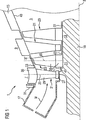
図1には、軸線3に沿って延びる断面環状の作動媒体M用流路5を備えたガスタービン1が示されている。その流路5内に多数の翼段が配置されている。特に第2静翼段9は軸線3に沿って第1静翼段7の後方に配置されている。また、第2動翼段13は第1動翼段11の後方に配置されている。その静翼段7、9はタービン車室15に環状に配置され流路5の中に半径方向に延びる多数の静翼21を有している。動翼段11、13はタービンロータ19に環状に配置され流路5の中に半径方向に延びる多数の動翼23を有している。作動媒体Mの流れはバーナ17によって燃焼ガスの形で発生される。流路5の環状断面に応じて、そのような多数のバーナ7は、図1の断面図に示されていない環状室の中に軸線3の周りに配置されている。
FIG. 1 shows a gas turbine 1 provided with a working medium M channel 5 having an annular cross section extending along an axis 3. Many blade stages are arranged in the flow path 5. In particular, the second stator blade stage 9 is arranged behind the first stator blade stage 7 along the axis 3. The
静翼21および動翼23が図1に概略的に示されている。静翼21は翼軸線25に沿って順々に配置された翼先端27と、羽根部29と、翼台座部31を有している。この翼台座部31は翼軸線25に対して横に延びる台座33と翼脚35を有している。
A
動翼23は翼軸線45に沿って順々に配置された翼先端37と、羽根部39と、翼台座部41を有している。この翼台座部41は翼軸線45に対して横に延びる台座43と翼脚47を有している。
The moving
静翼21の台座33および動翼23の台座43は、ガスタービン1を貫流する作動媒体Mの流路5の境界部49、51の一部を形成している。周辺境界部49はタービン車室15の一部である。ロータ側境界部51はガスタービン1の運転中に回転するタービンロータの一部である。
The
図1に概略的に示され、図2に詳細に示されているように、静翼21の台座33および動翼23の台座43は、羽根部29、39に固定の鋼板部によって形成されている。
As schematically shown in FIG. 1 and shown in detail in FIG. 2, the
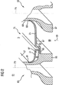
図2には、翼台座部31、41を代表して翼台座部61が示されている。図2に示された第1タービン翼63および第2タービン翼65は、第1静翼段7の第1静翼21および軸方向に直ぐ後ろに配置された第2静翼段9の第2静翼21を代表して示されている。第1タービン翼63および第2タービン翼65は、図1に示された第1動翼段11の第1動翼23および軸方向に直ぐ後ろに配置された第2動翼段13の第2動翼23をも代表して示されている。好適には、タービン翼63、65は静翼である。
In FIG. 2, a
第1タービン翼63は破断して示された羽根部69を有している。第2タービン翼65は破断して示された羽根部67を有している。第1タービン翼63および第2タービン翼65の場合、羽根部67、69の脚における翼台座部61に、翼軸線73、75に対して横に延びる台座71が形成されている。その台座71は一方では、第1タービン翼63に示された第1ばね弾性鋼板部79によって、他方では、第2タービン翼65に示された第2鋼板部77によって形成されている。第1ばね弾性鋼板部79は、第1タービン翼63において示された羽根部69の片側面に在る第1突き合わせ部83に取り付けられている。第2ばね弾性鋼板部77は、第2タービン翼65において示された羽根部67の反対側面に在る第2突き合わせ部81に取り付けられている。その取付けは例えば溶接あるいはろう付けで行われ、その場合気密に行われる。第1突き合わせ部83および第2突き合わせ部81はそれぞれ溝の形で形成され、その溝の中にそれぞれ、第1ばね弾性鋼板部79および第2鋼板部77の羽根部69ないし羽根部67で終わる縁が突っ込まれる。また第2ばね弾性鋼板部分77は第2タービン翼65の別の(第3)突き合わせ部85に保持されている。この実施例において、第2鋼板部77は第3突き合わせ部85に接合されている。第2鋼板部分77は、その代わりにあるいはそれに加えて、第3突き合わせ部85の後ろに引っ掛けることもできる。後者は、第2タービン翼65の第3突き合わせ部85に第2鋼板部77と共に保持される第1タービン翼63の第1ばね鋼板部79に当てはまる。このために、第1ばね鋼板部79は第3突き合わせ部85にゆるく後ろに引っ掛かる。この第3突き合わせ部85は第2鋼板部77および第1弾性鋼板部79を保持するために支え台の形に形成され、従って、その第1ばね弾性鋼板部79の側に、第1ばね弾性鋼板部79に対する支え台として用いるシール面を形成している。
The first turbine blade 63 has a blade portion 69 shown to be broken. The second turbine blade 65 has a blade portion 67 shown broken. In the case of the first turbine blade 63 and the second turbine blade 65, a pedestal 71 extending laterally with respect to the
上述したように、第1タービン翼63と第2タービン翼65との間において、第1タービン翼63の第1ばね弾性鋼板部79および第2タービン翼67の第2鋼板部77によって、流路5の連続した境界部87が形成されている。このようにして、第2鋼板部77および第1ばね弾性鋼板部79で境界部87を形成する薄肉かつ非支持の台座71の利用は、その鋼板部77、79のシール要素としての同時作用を可能にする。この形式のシール要素は同時に、隣接する第1タービン翼63と第2タービン翼65の相対運動を許すために十分に柔軟性を有し、それにもかかわらず、十分な漏れ止め作用を有する。これによって、互いに対向して位置する従来通常の台座において接合部を密封するために必要であったようなシール要素が省かれる。これによって、そのようなシール要素の構造的および熱的に不利な潜在的危険のある収容構造が回避される。
As described above, the flow path between the first turbine blade 63 and the second turbine blade 65 is determined by the first spring elastic
ここに図示された実施例の場合、台座71はその背面89がほとんど支持構造物あるいは支え台壁なしに済まされる。むしろ、背面89に、第1冷却室93および第2冷却室91が形成され、これらの冷却室93、91は、台座71を第2タービン翼65と第1タービン翼63との間の領域において最良に冷却することを可能にする。このようにして、さもなければ通常複雑に形成されねばならない台座周縁構造が、第3突き合わせ部85に関連して単純に、および熱的危険部位なしに形成できる。冷却室91、93における冷却を支援するために、タービン翼65、63の羽根部67、69の脚から出ている支持構造物95、97が、図1における翼脚35、47の形に形状的に最適に延長されている。
In the embodiment shown here, the pedestal 71 has its back surface 89 almost free of support structures or support pedestal walls. Rather, a first cooling chamber 93 and a second cooling chamber 91 are formed on the back surface 89, and these cooling chambers 93, 91 are configured so that the pedestal 71 is located in the region between the second turbine blade 65 and the first turbine blade 63. Allows for the best cooling. In this way, a pedestal peripheral structure that would otherwise have to be formed in a complex manner can be formed simply and without thermal hazards in relation to the third abutment 85. In order to support the cooling in the cooling chambers 91 and 93, the
好適には、図1に示された静翼21の形あるいは場合によっては図1に示された動翼23の形をした第1タービン翼63および第2タービン翼65の運転様式に応じて、特に第2鋼板部77および第1ばね弾性鋼板部79の第3突き合わせ部85に考慮された漏れ止め作用が生ずる。つまり、タービンロータ19における動翼23の形をしたタービン翼65、63の回転運転中、回転によって羽根部67、69の脚から羽根部67、69の方向99に作用する遠心力が発生される。加えて静翼21の場合のように圧力勾配も生ずる。第1ばね弾性鋼板部79がこの第1ばね弾性鋼板部79自体で発生するバイアス圧力によって第3突き合わせ部85に気密に接することも考えられる。これによって、圧力勾配で発生された押圧力が強められる。
Preferably, depending on the mode of operation of the first turbine blade 63 and the second turbine blade 65 in the form of the
タービン車室15における図1に示された静翼21の形をしたタービン翼65、63の運転中、台座71の背面89から冷却材によって、羽根部67、69の脚から羽根部67、69の方向99に向いた圧力勾配が発生する。動翼23における上述した遠心力の方向99並びに静翼21における圧力勾配の方向99は図2において矢印で明白にされている。即ち、動翼23あるいは静翼21としてのタービン翼67、69の構成に応じて、ばね弾性鋼板部77、79の形をした台座71は、遠心力によってないし圧力勾配によって、第3突き合わせ部85に押し付けられる。このようにして、台座71の鋼板部77、79は遠心力固着ないし圧縮固着され、同時に、燃焼ガスに曝される流路5と冷却材に曝される台座71の背面89との間の漏れ止め作用および分離作用を展開する。
During operation of the turbine blades 65 and 63 in the shape of the
要約すれば、ガスタービン1の流路5の境界部87をできるだけ単純に形成するために、翼軸線73、75に沿って配置された羽根部67、69と、羽根部67、69の脚に配置され翼軸線73、75に対して横に延びる台座71を有する翼台座部61とを備えたタービン翼63、65において、台座71が羽根部67、69に固定の鋼板部77、79によって形成されていることを提案する。これは、ガスタービン1の軸線3に沿って延びる断面環状の作動媒体M用流路5と、軸線3に沿って第1翼段7、11の後方に配置された第2翼段9、13とを備え、その各翼段7、9、11、13が上述した構想において環状に配置され半径方向に流路5の中に延びる多数のタービン翼63、65を有しているガスタービン1にも適用される。
In summary, in order to form the boundary portion 87 of the flow path 5 of the gas turbine 1 as simply as possible, the blade portions 67 and 69 arranged along the
1 ガスタービン
3 軸線
5 流路
7 第1静翼段
9 第2静翼段
11 第1動翼段
13 第2動翼段
63 第1タービン翼
65 第2タービン翼
67 羽根部
69 羽根部
71 台座
73 翼軸線
75 翼軸線
77 第2ばね弾性鋼板部
79 第1ばね弾性鋼板部
87 境界部
DESCRIPTION OF SYMBOLS 1 Gas turbine 3 Axis 5 Flow path 7 1st stationary blade stage 9 2nd stationary blade stage 11 1st moving
Claims (15)
Applications Claiming Priority (2)
| Application Number | Priority Date | Filing Date | Title |
|---|---|---|---|
| EP04001107A EP1557534A1 (en) | 2004-01-20 | 2004-01-20 | Turbine blade and gas turbine with such a turbine blade |
| PCT/EP2005/000223 WO2005068785A1 (en) | 2004-01-20 | 2005-01-12 | Turbine blade and gas turbine equipped with a turbine blade of this type |
Publications (2)
| Publication Number | Publication Date |
|---|---|
| JP2007518917A JP2007518917A (en) | 2007-07-12 |
| JP4499747B2 true JP4499747B2 (en) | 2010-07-07 |
Family
ID=34626466
Family Applications (1)
| Application Number | Title | Priority Date | Filing Date |
|---|---|---|---|
| JP2006548254A Expired - Fee Related JP4499747B2 (en) | 2004-01-20 | 2005-01-12 | Turbine blade and gas turbine equipped with the turbine blade |
Country Status (9)
| Country | Link |
|---|---|
| US (2) | US7607889B2 (en) |
| EP (2) | EP1557534A1 (en) |
| JP (1) | JP4499747B2 (en) |
| CN (1) | CN100400795C (en) |
| AT (1) | ATE520862T1 (en) |
| ES (1) | ES2370644T3 (en) |
| PL (1) | PL1706593T3 (en) |
| RU (1) | RU2332575C2 (en) |
| WO (1) | WO2005068785A1 (en) |
Families Citing this family (15)
| Publication number | Priority date | Publication date | Assignee | Title |
|---|---|---|---|---|
| US7766609B1 (en) * | 2007-05-24 | 2010-08-03 | Florida Turbine Technologies, Inc. | Turbine vane endwall with float wall heat shield |
| US20100003139A1 (en) * | 2008-07-03 | 2010-01-07 | Rotating Composite Technologies, Llc | Propulsor devices having variable pitch fan blades with spherical support and damping surfaces |
| AU2009296200B2 (en) * | 2008-09-29 | 2014-07-31 | Andrew L. Bender | High efficiency turbine |
| EP2282014A1 (en) * | 2009-06-23 | 2011-02-09 | Siemens Aktiengesellschaft | Ring-shaped flow channel section for a turbo engine |
| US8356975B2 (en) * | 2010-03-23 | 2013-01-22 | United Technologies Corporation | Gas turbine engine with non-axisymmetric surface contoured vane platform |
| US9976433B2 (en) | 2010-04-02 | 2018-05-22 | United Technologies Corporation | Gas turbine engine with non-axisymmetric surface contoured rotor blade platform |
| US8550785B2 (en) | 2010-06-11 | 2013-10-08 | Siemens Energy, Inc. | Wire seal for metering of turbine blade cooling fluids |
| RU2457336C1 (en) * | 2011-01-11 | 2012-07-27 | Светлана Владимировна Иванникова | Higher-efficiency turbine blading (versions) |
| US20170049331A1 (en) * | 2011-05-02 | 2017-02-23 | Canon Kabushiki Kaisha | Object information acquiring apparatus and method of controlling the same |
| US8961134B2 (en) * | 2011-06-29 | 2015-02-24 | Siemens Energy, Inc. | Turbine blade or vane with separate endwall |
| US11035238B2 (en) * | 2012-06-19 | 2021-06-15 | Raytheon Technologies Corporation | Airfoil including adhesively bonded shroud |
| US10344606B2 (en) * | 2013-04-01 | 2019-07-09 | United Technologies Corporation | Stator vane arrangement for a turbine engine |
| JP6547274B2 (en) | 2014-10-20 | 2019-07-24 | 株式会社デンソー | Particulate matter detection sensor |
| US10371162B2 (en) | 2016-10-05 | 2019-08-06 | Pratt & Whitney Canada Corp. | Integrally bladed fan rotor |
| US11852018B1 (en) * | 2022-08-10 | 2023-12-26 | General Electric Company | Turbine nozzle with planar surface adjacent side slash face |
Family Cites Families (14)
| Publication number | Priority date | Publication date | Assignee | Title |
|---|---|---|---|---|
| DE579989C (en) * | 1933-07-04 | Karl Roeder Dr Ing | No-head blading for axially loaded steam or gas turbines | |
| CH291898A (en) * | 1951-06-09 | 1953-07-15 | Escher Wyss Ag | Blading on rotors of centrifugal machines with axial flow, especially steam, gas turbines and compressors. |
| GB1119392A (en) * | 1966-06-03 | 1968-07-10 | Rover Co Ltd | Axial flow rotor for a turbine or the like |
| US3446481A (en) * | 1967-03-24 | 1969-05-27 | Gen Electric | Liquid cooled turbine rotor |
| DE1801475B2 (en) * | 1968-10-05 | 1971-08-12 | Daimler Benz Ag, 7000 Stuttgart | AIR-COOLED TURBINE BLADE |
| IT1079131B (en) | 1975-06-30 | 1985-05-08 | Gen Electric | IMPROVED COOLING APPLICABLE IN PARTICULAR TO ELEMENTS OF GAS TURBO ENGINES |
| FR2503247B1 (en) * | 1981-04-07 | 1985-06-14 | Snecma | IMPROVEMENTS ON THE FLOORS OF A GAS TURBINE OF TURBOREACTORS PROVIDED WITH AIR COOLING MEANS OF THE TURBINE WHEEL DISC |
| CH667493A5 (en) | 1985-05-31 | 1988-10-14 | Bbc Brown Boveri & Cie | DAMPING ELEMENT FOR DETACHED TURBO MACHINE BLADES. |
| GB2251897B (en) * | 1991-01-15 | 1994-11-30 | Rolls Royce Plc | A rotor |
| WO1999054597A1 (en) | 1998-04-21 | 1999-10-28 | Siemens Aktiengesellschaft | Turbine blade |
| US6431835B1 (en) * | 2000-10-17 | 2002-08-13 | Honeywell International, Inc. | Fan blade compliant shim |
| FR2831207B1 (en) * | 2001-10-24 | 2004-06-04 | Snecma Moteurs | PLATFORMS FOR BLADES OF A ROTARY ASSEMBLY |
| US6860722B2 (en) * | 2003-01-31 | 2005-03-01 | General Electric Company | Snap on blade shim |
| DE10340773A1 (en) | 2003-09-02 | 2005-03-24 | Man Turbomaschinen Ag | Rotor of a steam or gas turbine |
-
2004
- 2004-01-20 EP EP04001107A patent/EP1557534A1/en not_active Withdrawn
-
2005
- 2005-01-12 US US10/586,462 patent/US7607889B2/en not_active Expired - Fee Related
- 2005-01-12 EP EP05706868A patent/EP1706593B1/en not_active Not-in-force
- 2005-01-12 CN CNB2005800019558A patent/CN100400795C/en not_active Expired - Fee Related
- 2005-01-12 PL PL05706868T patent/PL1706593T3/en unknown
- 2005-01-12 ES ES05706868T patent/ES2370644T3/en active Active
- 2005-01-12 WO PCT/EP2005/000223 patent/WO2005068785A1/en active Application Filing
- 2005-01-12 JP JP2006548254A patent/JP4499747B2/en not_active Expired - Fee Related
- 2005-01-12 AT AT05706868T patent/ATE520862T1/en active
- 2005-01-12 RU RU2006129944/06A patent/RU2332575C2/en not_active IP Right Cessation
-
2009
- 2009-09-21 US US12/563,369 patent/US7963746B2/en not_active Expired - Fee Related
Also Published As
| Publication number | Publication date |
|---|---|
| PL1706593T3 (en) | 2012-01-31 |
| US7963746B2 (en) | 2011-06-21 |
| EP1706593A1 (en) | 2006-10-04 |
| CN100400795C (en) | 2008-07-09 |
| RU2332575C2 (en) | 2008-08-27 |
| ATE520862T1 (en) | 2011-09-15 |
| US20080232956A1 (en) | 2008-09-25 |
| EP1706593B1 (en) | 2011-08-17 |
| US7607889B2 (en) | 2009-10-27 |
| RU2006129944A (en) | 2008-02-27 |
| CN1906380A (en) | 2007-01-31 |
| ES2370644T3 (en) | 2011-12-21 |
| EP1557534A1 (en) | 2005-07-27 |
| WO2005068785A1 (en) | 2005-07-28 |
| US20100008773A1 (en) | 2010-01-14 |
| JP2007518917A (en) | 2007-07-12 |
Similar Documents
| Publication | Publication Date | Title |
|---|---|---|
| JP4499747B2 (en) | Turbine blade and gas turbine equipped with the turbine blade | |
| JP4584936B2 (en) | Turbine blade and gas turbine equipped with the turbine blade | |
| JP4721524B2 (en) | Leaf seal for gas turbine stator shroud and nozzle band | |
| JP5414200B2 (en) | Turbine rotor blade assembly and method of making the same | |
| JP3393184B2 (en) | Shroud assembly for gas turbine engine | |
| US5797723A (en) | Turbine flowpath seal | |
| JP4130581B2 (en) | Auxiliary seal for string hinge seal in gas turbine | |
| JP4124614B2 (en) | Turbine disk side plate | |
| JP2941698B2 (en) | Gas turbine rotor | |
| US10895156B2 (en) | Turbomachine arrangement with a platform cooling device for a blade of a turbomachine | |
| JP2007154889A (en) | Turbine nozzle and turbine engine | |
| JPS61157703A (en) | Stator assembly for rotaty machine | |
| JP2004092644A (en) | Disk rim of gas turbine engine equipped with cooling air slot cut back axially and skewed circumferentialy | |
| JP2006183492A (en) | Gas turbine | |
| JP2009008084A (en) | Device for cooling slot of rotor disk in turbomachine with two air supply | |
| JP2010065698A (en) | Shroud for turbo machine | |
| JP2007132351A (en) | Method and device for assembling turbine engine | |
| JPH0627483B2 (en) | Axial-flow gas turbine engine stator structure | |
| JP3310909B2 (en) | Gas turbine vane sealing device | |
| US10036255B2 (en) | Technique for cooling a root side of a platform of a turbomachine part | |
| JP3970156B2 (en) | Turbine blade ring structure | |
| US20020127103A1 (en) | Cooled gas turbine blade | |
| JP4395716B2 (en) | Seal plate structure | |
| JP2000192802A (en) | Circumferential wall which can be cooled of gas turbine or the like | |
| JP2600955B2 (en) | Double-flow steam turbine |
Legal Events
| Date | Code | Title | Description |
|---|---|---|---|
| A131 | Notification of reasons for refusal |
Free format text: JAPANESE INTERMEDIATE CODE: A131 Effective date: 20090714 |
|
| A521 | Request for written amendment filed |
Free format text: JAPANESE INTERMEDIATE CODE: A523 Effective date: 20090910 |
|
| RD03 | Notification of appointment of power of attorney |
Free format text: JAPANESE INTERMEDIATE CODE: A7423 Effective date: 20090910 |
|
| TRDD | Decision of grant or rejection written | ||
| A01 | Written decision to grant a patent or to grant a registration (utility model) |
Free format text: JAPANESE INTERMEDIATE CODE: A01 Effective date: 20100316 |
|
| A01 | Written decision to grant a patent or to grant a registration (utility model) |
Free format text: JAPANESE INTERMEDIATE CODE: A01 |
|
| A61 | First payment of annual fees (during grant procedure) |
Free format text: JAPANESE INTERMEDIATE CODE: A61 Effective date: 20100415 |
|
| FPAY | Renewal fee payment (event date is renewal date of database) |
Free format text: PAYMENT UNTIL: 20130423 Year of fee payment: 3 |
|
| R150 | Certificate of patent or registration of utility model |
Free format text: JAPANESE INTERMEDIATE CODE: R150 |
|
| FPAY | Renewal fee payment (event date is renewal date of database) |
Free format text: PAYMENT UNTIL: 20130423 Year of fee payment: 3 |
|
| FPAY | Renewal fee payment (event date is renewal date of database) |
Free format text: PAYMENT UNTIL: 20140423 Year of fee payment: 4 |
|
| R250 | Receipt of annual fees |
Free format text: JAPANESE INTERMEDIATE CODE: R250 |
|
| LAPS | Cancellation because of no payment of annual fees |