JP4497849B2 - Fuel cell container and fuel cell - Google Patents
Fuel cell container and fuel cell Download PDFInfo
- Publication number
- JP4497849B2 JP4497849B2 JP2003183147A JP2003183147A JP4497849B2 JP 4497849 B2 JP4497849 B2 JP 4497849B2 JP 2003183147 A JP2003183147 A JP 2003183147A JP 2003183147 A JP2003183147 A JP 2003183147A JP 4497849 B2 JP4497849 B2 JP 4497849B2
- Authority
- JP
- Japan
- Prior art keywords
- fuel cell
- electrode
- electrolyte member
- lid
- recess
- Prior art date
- Legal status (The legal status is an assumption and is not a legal conclusion. Google has not performed a legal analysis and makes no representation as to the accuracy of the status listed.)
- Expired - Fee Related
Links
Images


Classifications
-
- Y—GENERAL TAGGING OF NEW TECHNOLOGICAL DEVELOPMENTS; GENERAL TAGGING OF CROSS-SECTIONAL TECHNOLOGIES SPANNING OVER SEVERAL SECTIONS OF THE IPC; TECHNICAL SUBJECTS COVERED BY FORMER USPC CROSS-REFERENCE ART COLLECTIONS [XRACs] AND DIGESTS
- Y02—TECHNOLOGIES OR APPLICATIONS FOR MITIGATION OR ADAPTATION AGAINST CLIMATE CHANGE
- Y02E—REDUCTION OF GREENHOUSE GAS [GHG] EMISSIONS, RELATED TO ENERGY GENERATION, TRANSMISSION OR DISTRIBUTION
- Y02E60/00—Enabling technologies; Technologies with a potential or indirect contribution to GHG emissions mitigation
- Y02E60/30—Hydrogen technology
- Y02E60/50—Fuel cells
Description
【0001】
【発明の属する技術分野】
本発明は、電解質部材を収容可能なセラミックスから成る小型で高信頼性の燃料電池用容器およびそれを用いた燃料電池に関するものである。
【0002】
【従来の技術】
近年、これまでよりも低温で動作する小型燃料電池の開発が活発になされている。燃料電池には、これに用いる電解質の種類により、固体高分子電解質型燃料電池(Polymer Electrolyte Fuel Cell:以下、PEFCと記す)やリン酸型燃料電池、あるいは固体電解質型燃料電池といったものが知られている。
【0003】
中でもPEFCは、作動温度が80〜100℃程度という低温であり、
(1)出力密度が高く、小型化、軽量化が可能である、
(2)電解質が腐食性でなく、しかも作動温度が低いため、耐食性の面から電池構成材料の制約が少ないので、コスト低減が容易である、
(3)常温で起動できるため、起動時間が短い、
といった優れた特長を有している。このためPEFCは、以上のような特長を活かして、車両用の駆動電源や家庭用のコジェネレーションシステム等への適用ばかりでなく、携帯電話,PDA(Personal Digital Assistants),ノートパソコン,デジタルカメラやビデオ等の出力が数W〜数十Wの携帯電子機器用の電源としての用途が考えられてきている。
【0004】
PEFCは、大別して、例えば、白金や白金−ルテニウム等の触媒微粒子が付着した炭素電極から成る燃料極(カソード)と、白金等の触媒微粒子が付着した炭素電極から成る空気極(アノード)と、燃料極と空気極との間に介装されたフィルム状の電解質部材(以下、電解質部材と記す)とを有して構成されている。ここで、燃料極には、改質部を介して抽出された水素ガス(H2)が供給され、一方、空気極には、大気中の酸素ガス(O2)が供給されることにより、電気化学反応により所定の電気エネルギーが生成(発電)され、負荷に対する駆動電源(電圧/電流)となる電気エネルギーが生成される。
【0005】
具体的には、燃料極に水素ガス(H2)が供給されると、次の化学反応式(1)に示すように、上記触媒により電子(e−)が分離した水素イオン(プロトン;H+)が発生し、電解質部材を介して空気極側に通過するとともに、燃料極を構成する炭素電極により電子(e−)が取り出されて負荷に供給される。
【0006】
3H2→6H++6e−・・・(1)
一方、空気極に空気が供給されると、次の化学反応式(2)に示すように、上記触媒により負荷を経由した電子(e−)と電解質部材を通過した水素イオン(H+)と空気中の酸素ガス(O2)とが反応して水(H2O)が生成される。
【0007】
6H++3/2O2+6e−→3H2O・・・(2)
このような一連の電気化学反応(式(1)および式(2))は、概ね80〜100℃の比較的低温の温度条件で進行し、電力以外の副生成物は基本的に水(H2O)のみとなる。
【0008】
電解質部材を構成するイオン導電膜(交換膜)は、スルホン酸基を持つポリスチレン系の陽イオン交換膜、フルオロカーボンスルホン酸とポリビニリデンフルオライドとの混合膜、フルオロカーボンマトリックスにトリフルオロエチレンをグラフト化したもの等が知られており、最近ではパーフルオロカーボンスルホン酸膜(例えばナフィオン:商品名、デュポン社製)等が用いられている。
【0009】
図4に、従来の燃料電池(PEFC)の構成を断面図で示す。同図において、21はPEFC、23は電解質部材、24および25は電解質部材を挟持するように電解質部材23上に配置され、ガス拡散層および触媒層としての機能を有する一対の多孔質電極、すなわち燃料極および空気極であり、26はガスセパレータ、28は燃料流路、29は空気流路である。
【0010】
ガスセパレータ26は、ガスセパレータ26の外形を形成する積層部およびガス流入出枠と、燃料流路28と空気流路29とを分離するセパレータ部と、このセパレータ部を貫通するように設けられた、電解質部材23の燃料極24および空気極25に対応するように配置された電極とから構成されている。電解質部材23の燃料極24、空気極25が電気的に直列および/または並列に接続されるようにガスセパレータ26を介して多数積層して電池の最小単位である燃料電池スタックとし、この燃料電池スタックを、箱体に収納したものが一般的なPEFC本体である。
【0011】
ガスセパレータ26に形成された燃料流路28を通して燃料極24には改質器から水蒸気を含む燃料ガス(水素に富むガス)が供給され、また、空気極25には空気流路29を通して大気中から酸化剤ガスとして空気が供給され、電解質部材23での化学反応により発電される。
【0012】
【特許文献1】
特開2001−266910号公報
【0013】
【特許文献2】
特表2001−507501号公報
【0014】
【発明が解決しようとする課題】
しかしながら、このような高電圧、高容量の電池として従来より提案され開発されている燃料電池21は、スタック構造を有し構成要素が大面積化された大重量で大型の電池であり、小型電池としての燃料電池の利用は、従来はほとんど考えられていなかった。
【0015】
すなわち、このような燃料電池21における従来のガスセパレータ26には、これを用いて電解質部材23を積層した積層体において、電解質部材23の側面が外部に露出していることによって、携帯時の落下等により損傷を受けやすく、燃料電池21全体の機械的信頼性を確保し難いという問題点があった。
【0016】
また、携帯電子機器に燃料電池21を搭載するためには、従来の大型燃料とは異なった、コンパクト性、簡便性、安全性に優れる燃料電池用容器が必要になる。すなわち、汎用の化学電池のようなポータブル電源として適用するためには、作動温度までの温度上昇を短時間化するために、また熱容量を小さくするために、燃料電池用容器を小型化、低背化する必要があるが、従来の燃料電池21では熱容量の割合の大部分を占めるガスセパレータ26は、特にカーボン板の表面に切削加工で流路形成されるガスセパレータ26の場合など、薄肉化すると脆くなるため、数mmの厚みが必要である。このため、小型化、低背化が困難であるという問題点もあった。
【0017】
さらに、燃料電池21の出力電圧は、電解質部材23の表裏面の各電極24,25に供給されるガスの分圧によって決まる。すなわち、電解質部材23に供給された燃料ガスがガス流路28を進んで発電反応において消費されると、燃料極24の面上の燃料ガスの分圧が下がって出力電圧が下がる。これと同様に、空気も空気流路29を進んで消費されると、空気極25の面上の酸素の分圧が下がって出力電圧が下がる。従って、燃料ガスを均等に供給する必要があるが、従来の燃料電池21のガスセパレータ26は、特にカーボン板の表面に切削加工により流路を形成していることから、薄型化したときには流路の溝が狭くなるため、流路抵抗が大きくなり、均一なガス供給が困難であるという問題点もあった。
【0018】
また、複数の電解質部材23とその対向する燃料極24,空気極25とガスセパレータ26との組み合わせが、任意に効率よく直列接続または並列接続されて、全体の出力電圧および出力電流が調整されるようにする必要があるが、従来の燃料電池21では電解質部材23を挟む燃料極および空気極から電気を取り出すためには、外部に引き出し接続する方法か、もしくはガスセパレータ26を導電性材料として重ね合わせ直列接続する方法しかなく、小型燃料電池においてはそれが困難であるという問題点もあった。
【0019】
さらに、燃料流路28、空気流路29に供給される加湿水蒸気は、加湿が多くなりすぎると、ガスセパレータ26の流路内に水蒸気の結露により水滴が発生する。水滴の量が増加してくると、水滴が燃料流路28、空気流路29を塞いでしまい、この結果、燃料や空気が電解質部材23に供給され難くなり、電解質部材23での電気化学反応が阻害されるため発電効率が劣化してしまうという問題点もあった。
【0020】
特に、電解質部材23の空気極25側においては、電気化学反応により生成した水(H2O)が発生するため、この現象が発生しやすい。このため、仮に結露が発生したとしても、すみやかに流路から排出される特性を流路に持たせる必要がある。
【0021】
本発明は以上のような従来の技術の問題点に鑑み完成されたものであり、その目的は、電解質部材を収納可能な、小型で、堅牢な燃料電池用容器であり、また、ガスの均等供給、燃料電池容器内の温度勾配の均一化、高効率な電気接続、高効率な発電を図ることができる信頼性のある燃料電池用容器およびそれを用いた燃料電池を提供することにある。
【0022】
【課題を解決するための手段】
本発明の燃料電池用容器は、下側および上側主面にそれぞれ第1および第2電極を有する電解質部材を収容する凹部を上面に有するセラミックスから成る基体と、前記第1電極に対向する前記凹部の底面から前記基体の外面にかけて形成された第1流体流路と、前記基体に形成され、一端が対応する前記電解質部材の前記第1電極に前記凹部の底面で接続されるとともに、他端が前記基体の外面にかけて形成された少なくとも1つの第1配線導体と、前記基体の前記凹部の周囲の上面に前記凹部を覆って取着される、前記凹部を気密に封止するセラミックスから成る蓋体と、前記第2電極に対向する前記蓋体の下面から前記蓋体の外面にかけて形成された第2流体流路と、前記蓋体に形成され、一端が対応する前記電解質部材の第2電極に前記蓋体の下面で接続されるとともに、他端が前記蓋体の外面に導出された少なくとも1つの第2配線導体とを具備して成り、前記第1流体流路および前記第2流体流路の少なくとも一方の内面に撥水性膜が被着されていることを特徴とする。
【0023】
また、本発明の燃料電池用容器は、好ましくは、前記撥水性膜は金属膜から成ることを特徴とする。
【0024】
本発明の燃料電池は、上記構成の燃料電池用容器の前記凹部に電解質部材を収容して、該電解質部材の前記下側および上側主面を前記第1および第2流体流路との間でそれぞれの流体が供給あるいは排出されるように配置するとともに、前記第1および第2電極を前記第1および第2配線導体にそれぞれ電気的に接続し、前記基体の前記凹部の周囲の上面に前記凹部を覆って前記蓋体を取着して成ることを特徴とするものである。
【0025】
本発明の燃料電池用容器によれば、下側および上側主面にそれぞれ第1および第2電極を有する電解質部材を収容する凹部を上面に有するセラミックスから成る基体と、この基体の凹部の周囲の上面に凹部を覆って取着される、凹部を気密に封止するセラミックスから成る蓋体とを具備していることから、燃料電池用容器内を気密に封止することで、気体等の流体の漏れがなく、この容器の他にパッケージ等の容器を設ける必要がないので、効率良く動作させることができる燃料電池を得ることができるとともに、小型化にも有効なものとなる。また、凹部を上面に有するセラミックスから成る基体とこの凹部を封止する蓋体とで形成される箱体内に複数の電解質部材を収納して燃料電池とすることができるので、電解質部材が容器の外部に露出して損傷を受けたりすることがなく、燃料電池全体としての機械的信頼性が向上する。また、凹部および蓋体で構成される容器内部に一端が配設された第1および第2配線導体の他には電解質部材自体に無用な電気的接触をしないで済むので、信頼性および安全性の高い燃料電池を得ることができる。さらに、燃料電池用容器の構成材料としてセラミックスを用いたことにより、各種のガスを始めとする流体に対する耐食性に優れる燃料電池を得ることができる。
【0026】
また、第1電極に対向する凹部の底面から基体の外面にかけて形成された第1流体流路と、第2電極に対向する蓋体の下面から蓋体の外面にかけて形成された第2流体流路とを具備していることから、複数のそれぞれの流体流路は、電解質部材を挟んで、それぞれ対向する内壁面に設けられているため、電解質部材へ供給される流体の均一供給性を向上させることができる。このような流体経路によれば、流体が電解質部材に対して垂直に流れるため、例えば、流体が水素ガスと空気(酸素)ガスとの場合に、電解質部材が下側および上側主面にそれぞれ有する第1および第2電極に供給される各ガス分圧が下がることはなく、所定の安定した出力電圧を得ることができるという効果がある。さらに、供給される流体の圧力、例えばガス分圧が安定するため、燃料電池用容器の内部温度の分布が均一化され、その結果、電解質部材に生じる熱応力を抑制することができ、燃料電池の信頼性を向上させることができる。さらにまた、それぞれの流体流路は基体と蓋体とに形成されるため、各流路の密閉性に優れ、本来は流路的に隔絶されるべき2種類の原料流体(例えば酸素ガスと水素ガスもしくはメタノール等)が混合してしまうことによって燃料電池としての機能が発現されなくなるようなことがなく、また、可燃性の流体が高温で混合された後に引火、爆発を起こす危険性もないので、安全な燃料電池を提供することができる。
【0027】
また、第1流体流路および第2流体流路の少なくとも一方の内面の全面もしくは一部に被着された撥水性膜を具備していることから、第1流体流路の内面および第2流体流路の内面に結露した水や、電解質部材において電気化学反応により生成した水(H2O)は、撥水性膜で取り囲まれた流路において撥水性が上がるため、供給される燃料や空気の圧力により、容易に流路から排出、除去することができるため、第1および第2流体流路の水滴による閉塞を効果的に抑えることができる。そのため、第1および第2電極の電極表面が水(H2O)で覆われることを防止することができ、第1および第2流体流路を通して、燃料や大気中から酸化剤ガスとしての空気を効果的に供給することができるため、電解質部材での化学反応を促進することができ高効率な発電を行なうことが可能となる。
【0028】
また、撥水性膜は、金属膜から成るため、この方法によれば、従来の多層セラミック技術にて広く用いられているメタライズ形成及びメッキ処理により、簡易に撥水処理をすることができる。
【0029】
また、本発明の燃料電池によれば、本発明の燃料電池用容器の凹部に電解質部材を収容して、この電解質部材の下側および上側主面を第1および第2流体流路との間でそれぞれの流体が供給あるいは排出されるように配置するとともに、第1および第2電極を第1および第2配線導体にそれぞれ電気的に接続し、基体の凹部の周囲の上面に凹部を覆って蓋体を取着して成ることから、以上のような本発明の燃料電池用容器による特長を備えた、小型、堅牢で、ガスの均等供給、燃料電池容器内の温度勾配の均一化、高効率な電気接続を図ることができる信頼性のある燃料電池を得ることができる。
【0030】
従って、本発明の燃料電池用容器および燃料電池によれば、コンパクト性、簡便性、安全性に優れ、流体の均等供給、高効率な電気接続、高効率な発電により、長期にわたり安定して作動させることができる燃料電池を提供することができる。
【0031】
【発明の実施の形態】
次に、本発明を添付図面に基づき詳細に説明する。
【0032】
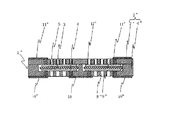
図1は本発明の燃料電池用容器およびそれを用いた燃料電池について実施の形態の一例を示す断面図である。図1において、1は燃料電池、2は燃料電池用容器、3は電解質部材、4は第1電極、5は第2電極、6は基体、7は蓋体、8は第1流体流路、9は第2流体流路、10は第1配線導体、11は第2配線導体、12は撥水性膜である。
【0033】
電解質部材3は、例えばイオン導電膜(交換膜)の両主面上に、下側主面に形成された第1電極4および上側主面に形成された第2電極5にそれぞれ対向するように、アノード側電極となる燃料極(図示せず)と、カソード側電極となる空気極(図示せず)とが一体的に形成されている。そして、電解質部材3で発電された電流を第1電極4,第2電極5へ流し、外部へ取り出すことができるものとなっている。
【0034】
このような電解質部材3のイオン導電膜(交換膜)は、パーフルオロカーボンスルフォン酸樹脂、例えばナフィオン(商品名、デュポン社製)等のプロトン伝導性のイオン交換樹脂により構成されている。また、燃料極および空気極は、多孔質状態のガス拡散電極であり、多孔質触媒層とガス拡散層の両方の機能を兼ね備えるものである。これらの燃料極および空気極は、白金,パラジウムあるいはこれらの合金等の触媒を担持した導電性微粒子、例えばカーボン微粒子をポリテトラフルオロエチレンのような疎水性樹脂結合剤により保持した多孔質体によって構成されている。
【0035】
電解質部材3の下側主面の第1電極4および上側主面の第2電極5は、白金や白金−ルテニウム等の触媒微粒子の付いた炭素電極を電解質部材3上にホットプレスする方法、または、白金や白金−ルテニウム等の触媒微粒子の付いた炭素電極材料と電解質材料を分散した溶液との混合物を電解質上に塗布または転写する方法等により形成される。
【0036】
燃料電池用容器2は、凹部を有する基体6と蓋体7とから成り、電解質部材3を凹部の内部に搭載して気密に封止する役割を持ち、酸化アルミニウム(Al2O3)質焼結体,ムライト(3Al2O3・2SiO2)質焼結体,炭化珪素(SiC)質焼結体,窒化アルミニウム(AlN)質焼結体,窒化珪素(Si3N4)質焼結体,ガラスセラミックス焼結体等のセラミックス材料で形成されている。
【0037】
なお、ガラスセラミックス焼結体はガラス成分とフィラー成分とから成るが、ガラス成分としては、例えばSiO2−B2O3系,SiO2−B2O3−Al2O3系,SiO2−B2O3−Al2O3−MO系(但し、MはCa,Sr,Mg,BaまたはZnを示す),SiO2−Al2O3−M1O−M2O系(但し、M1およびM2は同一または異なってCa,Sr,Mg,BaまたはZnを示す),SiO2−B2O3−Al2O3−M1O−M2O系(但し、M1およびM2は前記と同じである),SiO2−B2O3−M3 2O系(但し、M3はLi,NaまたはKを示す),SiO2−B2O3−Al2O3−M3 2O系(但し、M3は前記と同じである),Pb系ガラス,Bi系ガラス等が挙げられる。
【0038】
また、フィラー成分としては、例えばAl2O3,SiO2,ZrO2とアルカリ土類金属酸化物との複合酸化物、TiO2とアルカリ土類金属酸化物との複合酸化物、Al2O3およびSiO2から選ばれる少なくとも1種を含む複合酸化物(例えばスピネル,ムライト,コージェライト)等が挙げられる。
【0039】
燃料電池用容器2は、凹部を有する基体6と蓋体7とから成り、基体6の凹部の周囲に凹部を覆って蓋体7を取着することによって凹部を気密に封止するため、半田や銀ろう等の金属接合材料での接合、エポキシ等の樹脂材料での接合、凹部の周囲の上面に鉄合金等で作られたシールリング等を接合してシームウェルドやエレクトロンビームやレーザ等で溶接する方法等によって、蓋体7が基体6に取着される。なお、蓋体7にも基体6と同様の凹部を形成しておいてもよい。
【0040】
さらには、基体6の凹部の周囲や蓋体7の周囲に貫通穴を設け、直接ネジ締め等により気密に固定してもよい。
【0041】
基体6および蓋体7は、それぞれ厚みを薄くし、燃料電池1の低背化を可能とするためには、機械的強度である曲げ強度が200MPa以上であることが好ましい。
【0042】
基体6および蓋体7は、例えば相対密度が95%以上の緻密質からなる酸化アルミニウム質焼結体で形成されていることが好ましい。その場合であれば、例えば、まず酸化アルミニウム粉末に希土類酸化物粉末や焼結助剤を添加、混合して、酸化アルミニウム質焼結体の原料粉末を調整する。次いで、この酸化アルミニウム質焼結体の原料粉末に有機バインダおよび分散媒を添加、混合してペースト化し、このペーストからドクターブレード法によって、あるいは原料粉末に有機バインダを加え、プレス成形、圧延成形等によって、所定の厚みのグリーンシートを作製する。そして、このグリーンシートに対して、金型による打ち抜き、マイクロドリル、レーザ、プレス加工等により、第1流体流路8および第2流体流路9としての貫通穴や流路となる開口ならびに第1配線導体10および第2配線導体11を配設するための貫通孔を形成する。
【0043】
第1配線導体10および第2配線導体11は、酸化を防ぐために、タングステンおよび/またはモリブデンで形成されているのが好ましい。その場合であれば、例えば、無機成分としてタングステンおよび/またはモリブデン粉末100質量部に対して、Al2O3を3〜20質量部,Nb2O5を0.5〜5質量部の割合で添加してなる導体ペーストを調製する。この導体ペーストをグリーンシートの貫通孔内に充填して、貫通導体としてのビア導体を形成する。
【0044】
これらの導体ペースト中には、基体6や蓋体7のセラミックスとの密着性を高めるために、酸化アルミニウム粉末や、基体6や蓋体7を形成するセラミックス成分と同一の組成物粉末を、例えば0.05〜2体積%の割合で添加することも可能である。
【0045】
なお、基体6や蓋体7の表層および内層への第1配線導体10および第2配線導体11の形成は、貫通孔へ導体ペーストを充填してビア導体を形成する前後あるいはそれと同時に、同様の導体ペーストをグリーンシートに対しスクリーン印刷、グラビア印刷等の方法で所定パターンに印刷塗布して形成する。
【0046】
その後、導体ペーストを印刷し充填した所定枚数のシート状成形体を位置合わせして積層圧着した後、この積層体を、例えば非酸化性雰囲気中にて、焼成最高温度が1200〜1500℃の温度で焼成して、目的とするセラミックスの基体6や蓋体7および第1配線導体10,第2配線導体11を得る。
【0047】
また、セラミックスから成る基体6や蓋体7は、その厚みを0.2mm以上とすることが好ましい。厚みが0.2mm未満では、強度が被覆しがちなため、基体6に蓋体7を取着したときに発生する応力により、基体6および蓋体7に割れ等が発生しやすくなる傾向がある。他方、厚みが5mmを超えると、薄型化、低背化が困難となるため、小型携帯機器に搭載する燃料電池としては不適切となり、また、熱容量が大きくなるため、電解質部材3の電気化学反応条件に相当する適切な温度にすばやく設定することが困難となる傾向がある。
【0048】
第1配線導体10および第2配線導体11は、それぞれ電解質部材3の第1電極4および第2電極5に電気的に接続されて、電解質部材3で発電された電流を燃料電池用容器2の外部へ取り出すための導電路として機能する。
【0049】
第1配線導体10は、基体6の凹部の底面の電解質部材3の第1電極4に対向する部位に一端が配設され、他端が基体6の外面に導出されて形成されている。このような第1配線導体10は、前述のように基体6と一体的に形成され、第1配線導体10を第1電極4に接触させやすいように基体6の凹部の底面より、10μm以上高くするように形成するのが望ましい。この高さを得るためには、前述したように導体ペーストを印刷塗布して形成する際に、印刷条件を厚くするように設定すればよい。また、第1配線導体10は第1電極4に対向させて複数配置し、第1配線導体10による電気損失を減少させることが望ましく、第1配線導体10の基体6の貫通部についてはφ50μm以上の径とすることが好ましい。
【0050】
また、第2配線導体11は、蓋体7の下面の電解質部材3の第2電極5に対向する部位に一端が配設され、他端が蓋体7の外面に導出されて形成されている。このような第2配線導体11も、第1配線導体10と同様に、蓋体7と一体的に形成され、第2配線導体11を第2電極5に接触させやすいように蓋体7の凹部の底面より、10μm以上高くするように形成するのが望ましい。この高さを得るためには、前述したように導体ペーストを印刷塗布して形成する際に、印刷条件を厚くするように設定すればよい。また、第2配線導体11は第2電極5に対向させて複数配置し、第2配線導体11による電気損失を減少させることが望ましく、第2配線導体11の蓋体7の貫通部についてはφ50μm以上の径とすることが好ましい。
【0051】
これら第1配線導体10および第2配線導体11には、その露出する表面にニッケルや金から成る良導電性で、かつ耐蝕性およびロウ材との濡れ性が良好な金属をメッキ法により被着させておくと、第1配線導体10および第2配線導体11と、第1配線導体10および第2配線導体11ならびに外部電気回路との電気的接続を良好とすることができる。従って、第1配線導体10および第2配線導体11は、その露出する表面にニッケルや金から成る良導電性で、かつ耐蝕性およびロウ材との濡れ性が良好な金属をメッキ法により被着させておくことが好ましい。
【0052】
そして、これら第1および第2配線導体10,11と第1および第2電極4,5との電気的な接続は、基体6と蓋体7とで電解質部材3を挟み込むことによって、第1および第2配線導体10,11と第1および第2電極4,5とを圧着接触させて電気的接続させる等の構成によって行なえばよい。
【0053】
また、第1電極4および第2電極5に対向する基体6の凹部の底面および蓋体7の下面には、それぞれ第1流体流路8および第2流体流路9が配置されており、第1流体流路8は基体6の外面にかけて、また第2流体流路9は蓋体7の外面にかけて形成されている。これら第1および第2流体流路8,9は、それぞれ基体6や蓋体7に形成した貫通穴あるいは2次元、3次元的に形成された流路によって、燃料ガス例えば水素に富む改質ガス、あるいは酸化剤ガス例えば空気等の、電解質部材3へ供給される流体の通路として、あるいは反応で生成される水等の、反応後に電解質部材3から排出される流体の通路として設けられている。
【0054】
第1流体流路8および第2流体流路9として基体6および蓋体7に形成される貫通穴あるいは溝は、電解質部材3に均等に燃料ガスや酸化剤ガス等の流体が供給されるように、燃料電池1の仕様に応じて、貫通穴の径や数、あるいは溝の幅、深さ、配置を決めればよい。
【0055】
本発明の燃料電池用容器2および燃料電池1においては、第1流体流路8および第2流体流路9は、好適には、電解質部材3に均一な圧力で流体を流すため、φ0.1mm以上の穴径とし、間隔を一定にして配置するようにするとよい。
【0056】
このように電解質部材3の第1電極4が形成された下側主面に対向させて第1流体流路8を、第2電極5が形成された上側主面に対向させて第2流体流路9を形成したことによって、電解質部材3の下側および上側主面と第1および第2流体流路8,9との間で流体がやりとり可能となり、その流体がそれぞれの流路を通して供給あるいは排出されることとなる。そして、例えば流体としてガスを供給する場合であれば、電解質部材3の第1電極4および第2電極5にそれぞれ供給されるガス分圧が下がることをなくすことができ、所定の安定した出力電圧を得ることができる。さらに、供給されるガス分圧が安定するため、燃料電池1の内部圧力が均一化され、その結果、電解質部材3に生じる熱応力を抑制することができるので、燃料電池1の信頼性を向上させることができる。
【0057】
また、第1流体流路8の内面および第2流体流路9の内面の少なくとも一方の全部もしくは一部に被着された撥水性膜12が被着されている。これにより、水蒸気の結露により発生した水滴ならびに電解質部材3において電気化学反応で生成した水等をこの撥水性膜12によりすみやかに排出、除去することができるため、燃料や空気の流路となる第1および第2流体流路8,9の閉塞を効果的に防止することができる。そのため、第1および第2電極4,5の電極表面が水(H2O)で覆われることを効果的に防止することができ、第1および第2流体流路8,9を通して燃料や大気中から酸化剤ガスとして空気を効果的に供給することができるため、電解質部材3での電気化学反応を促進することができ高効率な発電を行なうことが可能となる。
【0058】
第1流体流路8の内面および第2流体流路9の内面の少なくとも一方に被着する撥水性膜12としては、タングステン、銅、銀、金等の金属メタライズおよび金等のメッキやフルオロカーボン系ポリマー、シランカップリング剤、テフロン(R)処理等の水(H2O)に対する撥水性材料を用いればよいが、特に金等のメッキにおいては、条件により表面粗さや緻密性等の変更により、水(H2O)に対する接触角を調整することが可能なため、所望の撥水特性を得やすい点で好ましいものである。
【0059】
これらによる撥水性膜12を第1流体流路8の内面や第2流体流路9の内面に被着させる場合、第1および第2流体流路8,9を通して大気中から酸化剤ガスとして空気の流れの均一性を保つためには、全ての第1および第2流体流路8,9に撥水性膜12を被着し、厚みとしては酸化剤ガスとしての空気を供給する際、損失圧力の影響を小さくする必要があるため、第1および第2流体流路8,9の開口面積に対して10%以下となる厚みとして被着形成することが好ましい。
【0060】
さらに、燃料や空気の流れにより撥水性膜12からの水滴の排出を促進するため、第1および第2流体流路8,9の内面全面に被着形成することが好ましい。また、これにより本発明の燃料電池用容器2および燃料電池1においては、例えば携帯用DMFC(直接形メタノール燃料電池)等の小型用タイプのものに使用してもよい。
【0061】
以上の構成により、図1に示すような、電解質部材3を収納可能な、小型で堅牢な燃料電池用容器2が得られ、高効率制御が可能な本発明の燃料電池1が得られる。
【0062】
本発明の燃料電池1は、具体的には携帯電話,PDA(Personal Digital Assistants),デジタルカメラ,ビデオカメラ,携帯型ゲーム機などの玩具等の携帯型電子機器、また、ノート型PC(パーソナルコンピュータ)をはじめとするポータブルなプリンター,ファックス,テレビ,通信機器,オーディオビデオ機器,扇風機等の各種家電製品,電動工具等の電子機器に電源として組み込まれるものであり、本発明の燃料電池1を用いた電子機器は、第1流体流路および第2流体流路の少なくとも一方の内面の全面もしくは一部に被着された撥水性膜を具備していることから、第1流体流路の内面および第2流体流路の内面に結露した水や、電解質部材において電気化学反応により生成した水(H2O)は、撥水性膜で取り囲まれた流路において撥水性が上がるため、供給される燃料や空気の圧力により、容易に流路から排出、除去することができるため、第1および第2流体流路の水滴による閉塞を効果的に抑えることができる。そのため、第1および第2電極の電極表面が水(H2O)で覆われることを防止することができ、第1および第2流体流路を通して、燃料や大気中から酸化剤ガスとしての空気を効果的に供給することができるため、電解質部材での化学反応を促進することができ、長期にわたり安定して作動させることができる電子機器を提供することができる。
【0063】
なお、本発明は以上の実施の形態の例に限定されるものではなく、本発明の要旨を逸脱しない範囲であれば、種々の変更を行なっても何ら差し支えない。例えば、第1流体流路や第2流体流路については、燃料電池全体を薄型化するため、基体または蓋体の側面からの流入口を設けるようにしてもよい。これによれば、特に携帯電子機器用として小型化を図る上で有効となる。さらに、第1および第2配線導体については、基体および蓋体の外面に導出される他端を、それぞれ同じ側の側面に引き出すように配設してよい。これによれば、燃料電池の一方側面に配線や流路等をまとめることができ、小型化と外部への接合部の保護とが容易となり、信頼性の高い設計が可能となるとともに、長期間安定した作動が可能な燃料電池となる。
【0064】
また、基体の凹部の内部には、複数の電解質部材を収容してこれらを第1および第2配線導体により電気的に接続して全体として高電圧あるいは大電流の出力を得るようにしてもよい。
【0065】
さらには、所望の電圧を得るために、基体および蓋体からなる容器単位体を厚み方向に積層し、直列ならびに並列接続に電気接続を行ってもよい。
【0066】
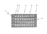
また、図2に本発明の燃料電池用容器およびそれを用いた燃料電池の実施の形態の他の例を断面図で示すように、凹部を有する基体6’の凹部のそれぞれに電解質部材3を収容するとともに、第1流体路8’および第2流体路9’の少なくとも一方は、凹部の底面に電解質部材3の下側主面または上側主面に対向するように、同じ長さで同じ幅の溝状の複数の開口が等間隔で形成された開口部13と、複数の開口の一端同士および他端同士をそれぞれ連結する連結部14と、連結部14の一方および他方から外面にかけて形成された流体の導入部15と排出部(図示せず)を設け、第1および第2電極4,5を第1および第2配線導体10’,11’にそれぞれ電気的に接続するようにしてもよい。これによれば、流体の導入部15と連結部14とにより複数の溝状に形成された開口部13への流体の供給が容易であり、開口部13における複数の溝状の開口は同じ長さで同じ幅で等間隔で形成されているため、流体の流入速度が速い場合においても、導入部15から排出部までの距離が短くなり、流路抵抗が小さくなる。その結果、電解質部材3へ供給される流体の均一供給性を向上させることができ、燃料や大気中から酸化剤ガスとして供給した空気により撥水性膜12上で結露によって発生した水(H2O)を、排出することが可能となる。さらに、第1,第2配線導体10’,11’により3次元的に自由に配線ができるため、複数の電解質部材3を任意に直列接続または並列接続することが可能となる。その結果、全体の出力電圧および出力電流を効率よく調整することが可能となるため、電解質部材3にて電気化学的に生成された電気を良好に外部に取り出すことができる燃料電池用容器2’および燃料電池1’となる。
【0067】
また、図3に本発明の燃料電池用容器およびそれを用いた燃料電池の実施の形態のさらに他の例を断面図で示すように、複数の凹部を有する基体6”の凹部のそれぞれに電解質部材3を収容するとともに、隣接する凹部の端部間にわたって第3配線導体16を配設し、複数の電解質部材3の第1電極4の間または第1電極4と第2電極5との間を電気的に接続し、両端となる位置に配置された電解質部材3に全体としての出力を取り出すように第1配線導体10”および第2配線導体11”をそれぞれに電気的に接続するようにしてもよい。これによれば、第1〜第3配線導体10”,11”,16により3次元的に自由に配線ができるため、複数の電解質部材3を任意に直列接続または並列接続することが可能となる。その結果、全体の出力電圧および出力電流を効率よく調整することが可能となるため、電解質部材3にて電気化学的に生成された電気を良好に外部に取り出すことができる燃料電池用容器2”および燃料電池1”となる。
【0068】
【発明の効果】
本発明の燃料電池用容器によれば、下側および上側主面にそれぞれ第1および第2電極を有する電解質部材を収容する凹部を上面に有するセラミックスから成る基体と、この基体の凹部の周囲の上面に凹部を覆って取着される、凹部を気密に封止するセラミックスから成る蓋体とを具備していることから、燃料電池用容器内を気密に封止することで、気体等の流体の漏れがなく、この容器の他にパッケージ等の容器を設ける必要がないので、効率良く動作させることができる燃料電池を得ることができるとともに、小型化にも有効なものとなる。また、凹部を上面に有するセラミックスから成る基体とこの凹部を封止する蓋体とで形成される箱体内に複数の電解質部材を収納して燃料電池とすることができるので、電解質部材が容器の外部に露出して損傷を受けたりすることがなく、燃料電池全体としての機械的信頼性が向上する。また、凹部および蓋体で構成される容器内部に一端が配設された第1および第2配線導体の他には電解質部材自体に無用な電気的接触をしないで済むので、信頼性および安全性の高い燃料電池を得ることができる。さらに、燃料電池用容器の構成材料としてセラミックスを用いたことにより、各種のガスを始めとする流体に対する耐食性に優れる燃料電池を得ることができる。
【0069】
また、第1電極に対向する凹部の底面から基体の外面にかけて形成された第1流体流路と、第2電極に対向する蓋体の下面から蓋体の外面にかけて形成された第2流体流路とを具備していることから、複数のそれぞれの流体流路は、電解質部材を挟んで、それぞれ対向する内壁面に設けられているため、電解質部材へ供給される流体の均一供給性を向上させることができる。このような流体経路によれば、流体が電解質部材に対して垂直に流れるため、例えば、流体が水素ガスと空気(酸素)ガスとの場合に、電解質部材が下側および上側主面にそれぞれ有する第1および第2電極に供給される各ガス分圧が下がることはなく、所定の安定した出力電圧を得ることができるという効果がある。さらに、供給される流体の圧力、例えばガス分圧が安定するため、燃料電池用容器の内部温度の分布が均一化され、その結果、電解質部材に生じる熱応力を抑制することができ、燃料電池の信頼性を向上させることができる。さらにまた、それぞれの流体流路は基体と蓋体とに形成されるため、各流路の密閉性に優れ、本来は流路的に隔絶されるべき2種類の原料流体(例えば酸素ガスと水素ガスもしくはメタノール等)が混合してしまうことによって燃料電池としての機能が発現されなくなるようなことがなく、また、可燃性の流体が高温で混合された後に引火、爆発を起こす危険性もないので、安全な燃料電池を提供することができる。
【0070】
また、第1流体流路および第2流体流路の少なくとも一方の内面に撥水性膜が被着されていることから、水蒸気が結露して生成した水滴をこの撥水性膜で排出、除去することができるため、燃料および空気の流路となる第1および第2流体流路の閉塞を効果的に抑えることができる。さらに、電解質部材において電気化学反応後に生じる水蒸気および一部水滴化した水をこの撥水性膜で排出、除去することができるため、第1および第2電極の電極表面が水蒸気および一部水滴化した水で覆われることを効果的に防止することができ、第1および第2流体流路を通して燃料や大気中から酸化剤ガスとして空気を効果的に供給することができるため、電解質部材での化学反応を促進することができ高効率な発電を行なうことが可能となる。
【0071】
また、本発明の燃料電池によれば、本発明の燃料電池用容器の凹部に電解質部材を収容して、この電解質部材の下側および上側主面を第1および第2流体流路との間でそれぞれの流体が供給あるいは排出されるように配置するとともに、第1および第2電極を第1および第2配線導体にそれぞれ電気的に接続し、基体の凹部の周囲の上面に凹部を覆って蓋体を取着して成ることから、電解質部材が露出して損傷を受けることがなく、また、凹部および蓋体で構成される容器内部に一端が配設された第1および第2配線導体の他には電解質部材に無用な電気的接触をしないで済むので、信頼性および安全性の高い燃料電池を得ることができる。また、第1および第2流体流路は、電解質部材を挟んで、それぞれ対向する内壁面である基体の凹部の底面および蓋体の下面に設けられているため、電解質部材へ供給されるガスの均一供給性を向上させることができ、電解質部材の第1および第2電極に供給されるガス分圧が下がることをなくすことができるので、所定の安定した出力電圧を得ることができる。そして、電解質部材に生じる応力も抑制することができ、信頼性を向上させることができる。
【0072】
従って、本発明の燃料電池用容器および燃料電池によれば、コンパクト性、簡便性、安全性に優れ、ガスの均等供給、高効率な電気接続により、長期にわたり安定して作動させることができる燃料電池を提供することができた。
【図面の簡単な説明】
【図1】本発明の燃料電池用容器およびそれを用いた本発明の燃料電池の実施の形態の一例を示す断面図である。
【図2】本発明の燃料電池用容器およびそれを用いた本発明の燃料電池の実施の形態の他の例を示す断面図である。
【図3】本発明の燃料電池用容器およびそれを用いた本発明の燃料電池の実施の形態のさらに他の例を示す断面図である。
【図4】従来の燃料電池の例を示す断面図である。
【符号の説明】
1,1’,1”:燃料電池
2,2’,2”:燃料電池用容器
3:電解質部材
4:第1電極
5:第2電極
6,6’,6”:基体
7,7’,7”:蓋体
8,8’,8”:第1流体流路
9,9’,9”:第2流体流路
10,10’,10”:第1配線導体
11,11’,11”:第2配線導体
12,12’,12”:撥水性膜
13:開口部
14:連結部
15:導入部
16:第3配線導体[0001]
BACKGROUND OF THE INVENTION
The present invention relates to a small and highly reliable fuel cell container made of ceramics that can accommodate an electrolyte member, and a fuel cell using the same.
[0002]
[Prior art]
In recent years, development of small fuel cells that operate at a lower temperature than before has been actively conducted. Depending on the type of electrolyte used for the fuel cell, a polymer electrolyte fuel cell (hereinafter referred to as PEFC), a phosphoric acid fuel cell, or a solid electrolyte fuel cell is known. ing.
[0003]
Among them, PEFC has a low operating temperature of about 80-100 ° C.
(1) The output density is high, and the size and weight can be reduced.
(2) Since the electrolyte is not corrosive and the operating temperature is low, since there are few restrictions on the battery constituent materials from the viewpoint of corrosion resistance, cost reduction is easy.
(3) Since it can be started at room temperature, the startup time is short.
It has excellent features such as For this reason, PEFC takes advantage of the features described above and is not only applied to driving power sources for vehicles and home cogeneration systems, but also to mobile phones, PDAs (Personal Digital Assistants), notebook computers, digital cameras, The use as a power source for portable electronic devices having an output of several watts to several tens of watts has been considered.
[0004]
The PEFC is roughly divided, for example, a fuel electrode (cathode) composed of a carbon electrode to which catalyst fine particles such as platinum and platinum-ruthenium are adhered, and an air electrode (anode) composed of a carbon electrode to which catalyst fine particles such as platinum are adhered, A film-like electrolyte member (hereinafter referred to as an electrolyte member) interposed between the fuel electrode and the air electrode is configured. Here, the fuel electrode is provided with hydrogen gas (H2) Is supplied to the air electrode, while oxygen gas (O2) Is generated (electric power generation) by the electrochemical reaction, and electric energy serving as a driving power source (voltage / current) for the load is generated.
[0005]
Specifically, hydrogen gas (H2) Is supplied, as shown in the following chemical reaction formula (1), electrons (e−) Separated hydrogen ions (protons; H+) Are generated and pass through the electrolyte member to the air electrode side, and electrons (e−) Is taken out and supplied to the load.
[0006]
3H2→ 6H++ 6e−... (1)
On the other hand, when air is supplied to the air electrode, as shown in the following chemical reaction formula (2), electrons (e−) And hydrogen ions (H+) And oxygen gas (O2) Reacts with water (H2O) is generated.
[0007]
6H++ 3 / 2O2+ 6e−→ 3H2O ... (2)
Such a series of electrochemical reactions (formula (1) and formula (2)) proceeds at a relatively low temperature condition of approximately 80 to 100 ° C., and by-products other than electric power are basically water (H2O) only.
[0008]
The ion conductive film (exchange membrane) constituting the electrolyte member is a polystyrene-based cation exchange membrane having a sulfonic acid group, a mixed membrane of fluorocarbon sulfonic acid and polyvinylidene fluoride, and trifluoroethylene grafted on a fluorocarbon matrix. Recently, a perfluorocarbon sulfonic acid membrane (for example, Nafion: trade name, manufactured by DuPont) or the like has been used.
[0009]
FIG. 4 is a sectional view showing the structure of a conventional fuel cell (PEFC). In the figure, 21 is a PEFC, 23 is an electrolyte member, 24 and 25 are arranged on the
[0010]
The
[0011]
A fuel gas containing water vapor (a gas rich in hydrogen) is supplied from the reformer to the
[0012]
[Patent Document 1]
JP 2001-266910 A
[0013]
[Patent Document 2]
Special table 2001-507501 gazette
[0014]
[Problems to be solved by the invention]
However, the
[0015]
That is, in the
[0016]
In addition, in order to mount the
[0017]
Further, the output voltage of the
[0018]
Further, the combination of the plurality of
[0019]
Furthermore, when the humidified water vapor supplied to the
[0020]
In particular, on the air electrode 25 side of the
[0021]
The present invention has been completed in view of the problems of the conventional techniques as described above, and an object of the present invention is a small and robust fuel cell container capable of accommodating an electrolyte member, and an equal gas. An object of the present invention is to provide a reliable fuel cell container and a fuel cell using the same that can achieve supply, uniform temperature gradient in the fuel cell container, highly efficient electrical connection, and highly efficient power generation.
[0022]
[Means for Solving the Problems]
A fuel cell container according to the present invention includes a base body made of ceramics having a recess on the upper surface for accommodating an electrolyte member having first and second electrodes on the lower and upper main surfaces, respectively.The first electrodeOppositeSaidFrom the bottom of the recessSaidA first fluid channel formed over the outer surface of the substrate;Formed on the substrate,One endAnd connected to the first electrode of the corresponding electrolyte member at the bottom surface of the recess.The other endSaidOn the outer surface of the substrateAt least one formed overA first wiring conductor;SaidSubstrateSaidOn the top surface around the recessSaidAttached over the recess,SaidSeal the recesses airtightMade of ceramicsA lid,The second electrodeOppositeSaidFrom the bottom of the lidSaidA second fluid channel formed over the outer surface of the lid, and the frontFormed in the lid,One endConnect to the corresponding second electrode of the electrolyte member at the bottom surface of the lidIsAndThe other endSaidLed to the outer surface of the lidAt least oneComprising a second wiring conductor;SaidA first fluid flow path andSaidA water repellent film is attached to at least one inner surface of the second fluid flow path.
[0023]
The fuel cell container of the present invention preferably hasSaidThe water repellent film is made of a metal film.
[0024]
The fuel cell of the present invention is a container for a fuel cell having the above structure.SaidAccommodating the electrolyte member in the recess,TheOf electrolyte componentsSaidLower and upper main surfacesSaidEach fluid between the first and second fluid flow pathsSupplied or dischargedAnd arrange asSaidThe first and second electrodesSaidElectrically connecting to the first and second wiring conductors respectively;SaidSubstrateSaidOn the top surface around the recessSaidCovering the recessSaidIt is characterized by attaching a lid.
[0025]
According to the fuel cell container of the present invention, a base body made of ceramics having a concave portion for accommodating an electrolyte member having first and second electrodes on the lower and upper main surfaces, respectively, and a periphery of the concave portion of the base body Covers the recess on the upper surface and seals the recess in an airtight mannerMade of ceramicsSince it has a lid, by sealing the fuel cell container in an airtight manner, there is no leakage of fluid such as gas, and there is no need to provide a container such as a package in addition to this container. A fuel cell that can be operated efficiently can be obtained, and it is also effective for downsizing. In addition, since a plurality of electrolyte members can be housed in a box formed by a ceramic body having a concave portion on the upper surface and a lid that seals the concave portion, a fuel cell can be obtained. The mechanical reliability of the entire fuel cell is improved without being exposed to the outside and being damaged. In addition to the first and second wiring conductors, one end of which is disposed inside the container constituted by the recess and the lid, unnecessary electrical contact with the electrolyte member itself can be avoided, so that reliability and safety are ensured. High fuel cell can be obtained. Furthermore, by using ceramics as the constituent material of the fuel cell container, it is possible to obtain a fuel cell having excellent corrosion resistance against fluids including various gases.
[0026]
Also,1st electrodeA first fluid channel formed from the bottom surface of the recess facing the outer surface of the substrate;Second electrodeA second fluid channel formed from the lower surface of the lid body facing the outer surface of the lid body to each of the plurality of fluid flow channels, the inner wall surfaces facing each other across the electrolyte member Therefore, the uniform supply property of the fluid supplied to the electrolyte member can be improved. According to such a fluid path, since the fluid flows perpendicularly to the electrolyte member, for example, when the fluid is hydrogen gas and air (oxygen) gas, the electrolyte member has on the lower and upper main surfaces, respectively. Each gas partial pressure supplied to the first and second electrodes does not decrease, and there is an effect that a predetermined stable output voltage can be obtained. Further, since the pressure of the fluid to be supplied, for example, the gas partial pressure is stabilized, the distribution of the internal temperature of the fuel cell container is made uniform, and as a result, the thermal stress generated in the electrolyte member can be suppressed. Reliability can be improved. Furthermore, since each fluid flow path is formed in the base and the lid, each of the flow paths is excellent in hermeticity, and originally two kinds of source fluids (for example, oxygen gas and hydrogen) that should be isolated in the flow path are used. Gas or methanol, etc.) will not function as a fuel cell, and there is no risk of ignition or explosion after a flammable fluid is mixed at a high temperature. A safe fuel cell can be provided.
[0027]
In addition, since it has a water-repellent film deposited on the whole or part of the inner surface of at least one of the first fluid channel and the second fluid channel, the inner surface of the first fluid channel and the second fluid Water condensed on the inner surface of the flow path or water generated by an electrochemical reaction in the electrolyte member (H2O) has higher water repellency in the flow path surrounded by the water repellent film, and therefore can be easily discharged and removed from the flow path by the pressure of the supplied fuel or air, so that the first and second fluids The blockage by the water droplet of a flow path can be suppressed effectively. Therefore, the electrode surfaces of the first and second electrodes are water (H2O) can be prevented, and air as an oxidant gas can be effectively supplied from the fuel and the atmosphere through the first and second fluid flow paths. The reaction can be promoted and highly efficient power generation can be performed.
[0028]
Further, since the water repellent film is made of a metal film, according to this method, the water repellent process can be easily performed by metallization formation and plating process widely used in the conventional multilayer ceramic technology.
[0029]
According to the fuel cell of the present invention, the electrolyte member is accommodated in the recess of the fuel cell container of the present invention, and the lower and upper main surfaces of the electrolyte member are between the first and second fluid flow paths. Each fluid isSupplied or dischargedAnd the first and second electrodes are electrically connected to the first and second wiring conductors, respectively, and the lid is attached to the upper surface around the recess of the base so as to cover the recess. With the features of the fuel cell container of the present invention as described above, it is compact and robust, and can reliably supply gas, uniform temperature gradient in the fuel cell container, and highly efficient electrical connection. A characteristic fuel cell can be obtained.
[0030]
Therefore, according to the fuel cell container and the fuel cell of the present invention, it is excellent in compactness, simplicity, and safety, and operates stably over a long period of time by the uniform supply of fluid, high-efficiency electrical connection, and high-efficiency power generation. The fuel cell which can be made to provide can be provided.
[0031]
DETAILED DESCRIPTION OF THE INVENTION
Next, the present invention will be described in detail with reference to the accompanying drawings.
[0032]
FIG. 1 is a cross-sectional view showing an example of an embodiment of a fuel cell container and a fuel cell using the same according to the present invention. In FIG. 1, 1 is a fuel cell, 2 is a fuel cell container, 3 is an electrolyte member, 4 is a first electrode, 5 is a second electrode, 6 is a base, 7 is a lid, 8 is a first fluid flow path, 9 is a second fluid flow path, 10 is a first wiring conductor, 11 is a second wiring conductor, and 12 is a water repellent film.
[0033]
For example, the
[0034]
The ion conductive film (exchange membrane) of the
[0035]
The
[0036]
The fuel cell container 2 includes a
[0037]
The glass ceramic sintered body is composed of a glass component and a filler component.2-B2O3System, SiO2-B2O3-Al2O3System, SiO2-B2O3-Al2O3-MO system (where M represents Ca, Sr, Mg, Ba or Zn), SiO2-Al2O3-M1OM2O system (however, M1And M2Are the same or different and represent Ca, Sr, Mg, Ba or Zn), SiO2-B2O3-Al2O3-M1OM2O system (however, M1And M2Is the same as above), SiO2-B2O3-M3 2O system (however, M3Represents Li, Na or K), SiO2-B2O3-Al2O3-M3 2O system (however, M3Is the same as described above), Pb-based glass, Bi-based glass and the like.
[0038]
Moreover, as a filler component, for example, Al2O3, SiO2, ZrO2And TiO, a complex oxide of alkaline earth metal oxides2Al oxide of alkaline earth metal oxide, Al2O3And SiO2And composite oxides containing at least one selected from (for example, spinel, mullite, cordierite).
[0039]
The fuel cell container 2 is composed of a
[0040]
Furthermore, a through hole may be provided around the concave portion of the
[0041]
In order to reduce the thickness of the
[0042]
The
[0043]
The
[0044]
In these conductor pastes, in order to improve the adhesion of the
[0045]
The formation of the
[0046]
Then, after aligning and laminating and pressing a predetermined number of sheet-like molded bodies filled with printed conductor paste, the laminated body is heated at a maximum firing temperature of 1200 to 1500 ° C., for example, in a non-oxidizing atmosphere. To obtain the target
[0047]
Moreover, it is preferable that the base |
[0048]
The
[0049]
The
[0050]
The
[0051]
The
[0052]
The first and
[0053]
In addition, a first
[0054]
Through holes or grooves formed in the
[0055]
In the fuel cell container 2 and the fuel cell 1 of the present invention, the first
[0056]
In this way, the first
[0057]
Further, a
[0058]
Examples of the water-
[0059]
When the water-
[0060]
Furthermore, in order to promote the discharge of water droplets from the water-
[0061]
With the above configuration, a small and robust fuel cell container 2 capable of accommodating the
[0062]
Specifically, the fuel cell 1 of the present invention includes portable electronic devices such as toys such as mobile phones, PDAs (Personal Digital Assistants), digital cameras, video cameras, and portable game machines, and notebook PCs (personal computers). ) And other portable printers, fax machines, televisions, communication devices, audio-video devices, electric appliances such as electric fans, and electronic devices such as electric tools as power sources. The fuel cell 1 of the present invention is used. Since the electronic apparatus includes a water-repellent film that is attached to the whole or part of at least one inner surface of the first fluid channel and the second fluid channel, the inner surface of the first fluid channel and Water condensed on the inner surface of the second fluid channel or water generated by an electrochemical reaction in the electrolyte member (H2O) has higher water repellency in the flow path surrounded by the water repellent film, and therefore can be easily discharged and removed from the flow path by the pressure of the supplied fuel or air, so that the first and second fluids The blockage by the water droplet of a flow path can be suppressed effectively. Therefore, the electrode surfaces of the first and second electrodes are water (H2O) can be prevented, and air as an oxidant gas can be effectively supplied from the fuel and the atmosphere through the first and second fluid flow paths. An electronic device that can promote the reaction and can be stably operated over a long period of time can be provided.
[0063]
It should be noted that the present invention is not limited to the embodiments described above, and various modifications can be made without departing from the scope of the present invention. For example, with respect to the first fluid channel and the second fluid channel, an inflow port from the side surface of the base body or the lid may be provided in order to reduce the thickness of the entire fuel cell. This is effective in reducing the size especially for portable electronic devices. Furthermore, about the 1st and 2nd wiring conductor, you may arrange | position so that the other end derived | led-out to the outer surface of a base | substrate and a cover body may each be pulled out to the side surface of the same side. According to this, wiring and flow paths can be integrated on one side of the fuel cell, facilitating downsizing and protection of joints to the outside, enabling a highly reliable design, and The fuel cell can be operated stably.
[0064]
Further, a plurality of electrolyte members may be accommodated in the concave portion of the base body, and these may be electrically connected by the first and second wiring conductors to obtain a high voltage or large current output as a whole. .
[0065]
Furthermore, in order to obtain a desired voltage, container units composed of a base and a lid may be stacked in the thickness direction, and electrical connection may be made in series and parallel connection.
[0066]
In addition, as shown in a cross-sectional view of another example of the fuel cell container of the present invention and a fuel cell using the same in FIG. 2, an
[0067]
Further, as shown in a cross-sectional view in FIG. 3, a fuel cell container of the present invention and a fuel cell using the same are shown in a cross-sectional view. While accommodating the
[0068]
【The invention's effect】
According to the fuel cell container of the present invention, a base body made of ceramics having a concave portion for accommodating an electrolyte member having first and second electrodes on the lower and upper main surfaces, respectively, and a periphery of the concave portion of the base body Covers the recess on the upper surface and seals the recess in an airtight mannerMade of ceramicsSince it has a lid, by sealing the fuel cell container in an airtight manner, there is no leakage of fluid such as gas, and there is no need to provide a container such as a package in addition to this container. A fuel cell that can be operated efficiently can be obtained, and it is also effective for downsizing. In addition, since a plurality of electrolyte members can be housed in a box formed by a ceramic body having a concave portion on the upper surface and a lid that seals the concave portion, a fuel cell can be obtained. The mechanical reliability of the entire fuel cell is improved without being exposed to the outside and being damaged. In addition to the first and second wiring conductors, one end of which is disposed inside the container constituted by the recess and the lid, unnecessary electrical contact with the electrolyte member itself can be avoided, so that reliability and safety are ensured. High fuel cell can be obtained. Furthermore, by using ceramics as the constituent material of the fuel cell container, it is possible to obtain a fuel cell having excellent corrosion resistance against fluids including various gases.
[0069]
Also,1st electrodeA first fluid channel formed from the bottom surface of the recess facing the outer surface of the substrate;Second electrodeA second fluid channel formed from the lower surface of the lid body facing the outer surface of the lid body to each of the plurality of fluid flow channels, the inner wall surfaces facing each other across the electrolyte member Therefore, the uniform supply property of the fluid supplied to the electrolyte member can be improved. According to such a fluid path, since the fluid flows perpendicularly to the electrolyte member, for example, when the fluid is hydrogen gas and air (oxygen) gas, the electrolyte member has on the lower and upper main surfaces, respectively. Each gas partial pressure supplied to the first and second electrodes does not decrease, and there is an effect that a predetermined stable output voltage can be obtained. Further, since the pressure of the fluid to be supplied, for example, the gas partial pressure is stabilized, the distribution of the internal temperature of the fuel cell container is made uniform, and as a result, the thermal stress generated in the electrolyte member can be suppressed. Reliability can be improved. Furthermore, since each fluid flow path is formed in the base and the lid, each of the flow paths is excellent in hermeticity, and originally two kinds of source fluids (for example, oxygen gas and hydrogen) that should be isolated in the flow path are used. Gas or methanol, etc.) will not function as a fuel cell, and there is no risk of ignition or explosion after a flammable fluid is mixed at a high temperature. A safe fuel cell can be provided.
[0070]
Further, since the water repellent film is attached to the inner surface of at least one of the first fluid channel and the second fluid channel, water droplets generated by condensation of water vapor are discharged and removed by the water repellent film. Therefore, the blockage of the first and second fluid flow paths serving as fuel and air flow paths can be effectively suppressed. Furthermore, since water vapor generated after the electrochemical reaction and partially water-dropped water in the electrolyte member can be discharged and removed by this water-repellent film, the electrode surfaces of the first and second electrodes are water-vapor and partially water-dropped. Since it can be effectively prevented from being covered with water and air can be effectively supplied as an oxidant gas from the fuel and the atmosphere through the first and second fluid flow paths, the chemistry in the electrolyte member The reaction can be promoted and highly efficient power generation can be performed.
[0071]
According to the fuel cell of the present invention, the electrolyte member is accommodated in the recess of the fuel cell container of the present invention, and the lower and upper main surfaces of the electrolyte member are between the first and second fluid flow paths. Each fluid isSupplied or dischargedAnd the first and second electrodes are electrically connected to the first and second wiring conductors, respectively, and the lid is attached to the upper surface around the recess of the base so as to cover the recess. The electrolyte member is not exposed and damaged, and in addition to the first and second wiring conductors, one end of which is disposed inside the container constituted by the concave portion and the lid, useless electricity for the electrolyte member Therefore, it is possible to obtain a fuel cell with high reliability and safety. In addition, since the first and second fluid flow paths are provided on the bottom surface of the concave portion of the base body and the lower surface of the lid body, which are the inner wall surfaces facing each other with the electrolyte member interposed therebetween, the gas supplied to the electrolyte member The uniform supply can be improved and the partial pressure of the gas supplied to the first and second electrodes of the electrolyte member can be prevented from decreasing, so that a predetermined stable output voltage can be obtained. And the stress which arises in an electrolyte member can also be suppressed and reliability can be improved.
[0072]
Therefore, according to the fuel cell container and the fuel cell of the present invention, the fuel is excellent in compactness, simplicity, and safety, and can be stably operated over a long period of time by uniform gas supply and high-efficiency electrical connection. Batteries could be provided.
[Brief description of the drawings]
FIG. 1 is a cross-sectional view showing an example of an embodiment of a fuel cell container of the present invention and a fuel cell of the present invention using the same.
FIG. 2 is a cross-sectional view showing another example of an embodiment of a fuel cell container of the present invention and a fuel cell of the present invention using the same.
FIG. 3 is a cross-sectional view showing still another example of an embodiment of a fuel cell container of the present invention and a fuel cell of the present invention using the same.
FIG. 4 is a cross-sectional view showing an example of a conventional fuel cell.
[Explanation of symbols]
1, 1 ', 1 ": Fuel cell
2, 2 ', 2 ": Container for fuel cell
3: Electrolyte member
4: First electrode
5: Second electrode
6, 6 ', 6 ": substrate
7, 7 ', 7 ": lid
8, 8 ', 8 ": first fluid flow path
9, 9 ', 9 ": second fluid flow path
10, 10 ', 10 ": first wiring conductor
11, 11 ', 11 ": second wiring conductor
12, 12 ', 12 ": Water repellent film
13: Opening
14: Connection part
15: Introduction
16: Third wiring conductor
Claims (3)
Priority Applications (3)
| Application Number | Priority Date | Filing Date | Title |
|---|---|---|---|
| JP2003183147A JP4497849B2 (en) | 2003-06-26 | 2003-06-26 | Fuel cell container and fuel cell |
| US10/691,451 US20040146772A1 (en) | 2002-10-21 | 2003-10-20 | Fuel cell casing, fuel cell and electronic apparatus |
| DE10348785A DE10348785B4 (en) | 2002-10-21 | 2003-10-21 | Fuel cell housing, fuel cell and electronic device |
Applications Claiming Priority (1)
| Application Number | Priority Date | Filing Date | Title |
|---|---|---|---|
| JP2003183147A JP4497849B2 (en) | 2003-06-26 | 2003-06-26 | Fuel cell container and fuel cell |
Publications (2)
| Publication Number | Publication Date |
|---|---|
| JP2005019237A JP2005019237A (en) | 2005-01-20 |
| JP4497849B2 true JP4497849B2 (en) | 2010-07-07 |
Family
ID=34183330
Family Applications (1)
| Application Number | Title | Priority Date | Filing Date |
|---|---|---|---|
| JP2003183147A Expired - Fee Related JP4497849B2 (en) | 2002-10-21 | 2003-06-26 | Fuel cell container and fuel cell |
Country Status (1)
| Country | Link |
|---|---|
| JP (1) | JP4497849B2 (en) |
Families Citing this family (1)
| Publication number | Priority date | Publication date | Assignee | Title |
|---|---|---|---|---|
| EP3101721B1 (en) * | 2014-01-28 | 2018-10-10 | Murata Manufacturing Co., Ltd. | Solid oxide fuel cell and solid oxide fuel cell stack |
Citations (5)
| Publication number | Priority date | Publication date | Assignee | Title |
|---|---|---|---|---|
| JPH09298064A (en) * | 1996-03-08 | 1997-11-18 | Fuji Electric Co Ltd | Solid polymer electrolytic fuel cell |
| JPH11339827A (en) * | 1998-05-28 | 1999-12-10 | Matsushita Electric Ind Co Ltd | Solid polymer fuel cell |
| JP2002246039A (en) * | 2001-02-16 | 2002-08-30 | Seijiro Suda | Liquid fuel cell |
| JP2002270209A (en) * | 2001-03-06 | 2002-09-20 | Sharp Corp | Solid polymer fuel cell |
| JP2004522257A (en) * | 2000-11-14 | 2004-07-22 | ザ リージェンツ オブ ザ ユニバーシティ オブ カリフォルニア | Methanol fuel cell with air breathing |
-
2003
- 2003-06-26 JP JP2003183147A patent/JP4497849B2/en not_active Expired - Fee Related
Patent Citations (5)
| Publication number | Priority date | Publication date | Assignee | Title |
|---|---|---|---|---|
| JPH09298064A (en) * | 1996-03-08 | 1997-11-18 | Fuji Electric Co Ltd | Solid polymer electrolytic fuel cell |
| JPH11339827A (en) * | 1998-05-28 | 1999-12-10 | Matsushita Electric Ind Co Ltd | Solid polymer fuel cell |
| JP2004522257A (en) * | 2000-11-14 | 2004-07-22 | ザ リージェンツ オブ ザ ユニバーシティ オブ カリフォルニア | Methanol fuel cell with air breathing |
| JP2002246039A (en) * | 2001-02-16 | 2002-08-30 | Seijiro Suda | Liquid fuel cell |
| JP2002270209A (en) * | 2001-03-06 | 2002-09-20 | Sharp Corp | Solid polymer fuel cell |
Also Published As
| Publication number | Publication date |
|---|---|
| JP2005019237A (en) | 2005-01-20 |
Similar Documents
| Publication | Publication Date | Title |
|---|---|---|
| US20060115707A1 (en) | Fuel cell casing and fuel cell | |
| JP3774445B2 (en) | Fuel cell container and fuel cell | |
| JP3968028B2 (en) | Fuel cell container and manufacturing method thereof | |
| JP4531019B2 (en) | Fuel cell | |
| JP3774434B2 (en) | Fuel cell container and fuel cell | |
| JP3740459B2 (en) | Fuel cell container and fuel cell | |
| JP4497849B2 (en) | Fuel cell container and fuel cell | |
| JP3774442B2 (en) | Fuel cell container and fuel cell | |
| JP3774443B2 (en) | Fuel cell container and fuel cell | |
| JP3894878B2 (en) | Fuel cell container and fuel cell | |
| JP3740455B2 (en) | Fuel cell container and fuel cell | |
| JP3740464B2 (en) | Fuel cell container and fuel cell | |
| JP3740463B2 (en) | Fuel cell container and fuel cell | |
| JP4544836B2 (en) | Fuel cell container and fuel cell | |
| JP4268490B2 (en) | Fuel cell container, fuel cell and electronic device | |
| JP5093969B2 (en) | Fuel cell container, fuel cell and electronic device | |
| JP4693377B2 (en) | Fuel cell container, fuel cell and electronic device | |
| JP4565817B2 (en) | Fuel cell container and fuel cell | |
| JP4511145B2 (en) | Fuel cell container, fuel cell and electronic device | |
| JP4986374B2 (en) | Fuel cell container, fuel cell and electronic device | |
| JP4484474B2 (en) | Fuel cell container and fuel cell | |
| JP4828799B2 (en) | Fuel cell container, fuel cell and electronic device | |
| JP2007134349A (en) | Container for fuel cell, method of manufacturing same, and fuel cell | |
| JP2004355935A (en) | Fuel cell container and fuel cell |
Legal Events
| Date | Code | Title | Description |
|---|---|---|---|
| A621 | Written request for application examination |
Free format text: JAPANESE INTERMEDIATE CODE: A621 Effective date: 20060518 |
|
| A977 | Report on retrieval |
Free format text: JAPANESE INTERMEDIATE CODE: A971007 Effective date: 20080206 |
|
| A131 | Notification of reasons for refusal |
Free format text: JAPANESE INTERMEDIATE CODE: A131 Effective date: 20091222 |
|
| A521 | Written amendment |
Free format text: JAPANESE INTERMEDIATE CODE: A523 Effective date: 20100218 |
|
| TRDD | Decision of grant or rejection written | ||
| A01 | Written decision to grant a patent or to grant a registration (utility model) |
Free format text: JAPANESE INTERMEDIATE CODE: A01 Effective date: 20100316 |
|
| A01 | Written decision to grant a patent or to grant a registration (utility model) |
Free format text: JAPANESE INTERMEDIATE CODE: A01 |
|
| A61 | First payment of annual fees (during grant procedure) |
Free format text: JAPANESE INTERMEDIATE CODE: A61 Effective date: 20100413 |
|
| FPAY | Renewal fee payment (event date is renewal date of database) |
Free format text: PAYMENT UNTIL: 20130423 Year of fee payment: 3 |
|
| R150 | Certificate of patent or registration of utility model |
Free format text: JAPANESE INTERMEDIATE CODE: R150 |
|
| FPAY | Renewal fee payment (event date is renewal date of database) |
Free format text: PAYMENT UNTIL: 20140423 Year of fee payment: 4 |
|
| LAPS | Cancellation because of no payment of annual fees |