JP4828799B2 - Fuel cell container, fuel cell and electronic device - Google Patents
Fuel cell container, fuel cell and electronic device Download PDFInfo
- Publication number
- JP4828799B2 JP4828799B2 JP2004084277A JP2004084277A JP4828799B2 JP 4828799 B2 JP4828799 B2 JP 4828799B2 JP 2004084277 A JP2004084277 A JP 2004084277A JP 2004084277 A JP2004084277 A JP 2004084277A JP 4828799 B2 JP4828799 B2 JP 4828799B2
- Authority
- JP
- Japan
- Prior art keywords
- fuel cell
- electrode
- wiring conductor
- lid
- flow path
- Prior art date
- Legal status (The legal status is an assumption and is not a legal conclusion. Google has not performed a legal analysis and makes no representation as to the accuracy of the status listed.)
- Expired - Fee Related
Links
Images


Classifications
-
- Y—GENERAL TAGGING OF NEW TECHNOLOGICAL DEVELOPMENTS; GENERAL TAGGING OF CROSS-SECTIONAL TECHNOLOGIES SPANNING OVER SEVERAL SECTIONS OF THE IPC; TECHNICAL SUBJECTS COVERED BY FORMER USPC CROSS-REFERENCE ART COLLECTIONS [XRACs] AND DIGESTS
- Y02—TECHNOLOGIES OR APPLICATIONS FOR MITIGATION OR ADAPTATION AGAINST CLIMATE CHANGE
- Y02E—REDUCTION OF GREENHOUSE GAS [GHG] EMISSIONS, RELATED TO ENERGY GENERATION, TRANSMISSION OR DISTRIBUTION
- Y02E60/00—Enabling technologies; Technologies with a potential or indirect contribution to GHG emissions mitigation
- Y02E60/30—Hydrogen technology
- Y02E60/50—Fuel cells
Landscapes
- Fuel Cell (AREA)
Description
本発明は、電解質部材を収容するセラミックスから成る小型で高信頼性の燃料電池用容器およびそれを用いた燃料電池ならびに電子機器に関する。 The present invention relates to a small and highly reliable fuel cell container made of ceramics that accommodates an electrolyte member, a fuel cell using the same, and an electronic device.
近年、これまでよりも低温で動作する小型燃料電池の開発が活発になされている。燃料電池には、これに用いる電解質の種類により、固体高分子電解質型燃料電池(Polymer Electrolyte Fuel Cell:以下、PEFCと記す)やリン酸型燃料電池、あるいは固体電解質型燃料電池といったものが知られている。 In recent years, development of small fuel cells that operate at a lower temperature than before has been actively conducted. Depending on the type of electrolyte used for the fuel cell, a polymer electrolyte fuel cell (hereinafter referred to as PEFC), a phosphoric acid fuel cell, or a solid electrolyte fuel cell is known. ing.
中でもPEFCは、作動温度が80〜100℃程度という低温であり、
(1)出力密度が高く、小型化、軽量化が可能である、
(2)電解質が腐食性でなく、しかも作動温度が低いため、耐食性の面から電池構成材料の制約が少ないので、コスト低減が容易である、
(3)常温で起動できるため、起動時間が短い、
といった優れた特長を有している。このためPEFCは、以上のような特長を活かして、車両用の駆動電源や家庭用のコジェネレーションシステム等への適用ばかりでなく、携帯電話、PDA(Personal Digital Assistants)、ノートパソコン、デジタルカメラやビデオカメラ等の出力が数W〜数十Wの携帯電子機器用の電源としての用途が考えられてきている。
Among them, PEFC has a low operating temperature of about 80-100 ° C,
(1) The output density is high, and the size and weight can be reduced.
(2) Since the electrolyte is not corrosive and the operating temperature is low, since there are few restrictions on the battery constituent materials from the viewpoint of corrosion resistance, cost reduction is easy.
(3) Since it can be started at room temperature, the startup time is short.
It has excellent features such as For this reason, PEFC takes advantage of the above features and is not only applied to driving power sources for vehicles and cogeneration systems for homes, but also to mobile phones, PDAs (Personal Digital Assistants), laptop computers, digital cameras, The use as a power source for portable electronic devices whose output of a video camera or the like has several W to several tens of W has been considered.
PEFCは、大別して、例えば、白金や白金−ルテニウム等の触媒微粒子が付着した炭素電極から成る燃料極(カソード)と、白金等の触媒微粒子が付着した炭素電極から成る空気極(アノード)と、燃料極と空気極との間に介装されたフィルム状の電解質部材(以下、電解質部材と記す)とを有して構成されている。ここで、燃料極には、改質部を介して抽出された水素ガス(H2)が供給され、一方、空気極には、大気中の酸素ガス(O2)が供給されることにより、電気化学反応により所定の電気エネルギーが生成(発電)され、負荷に対する駆動電源(電圧/電流)となる電気エネルギーが生成される。 The PEFC is roughly divided, for example, a fuel electrode (cathode) composed of a carbon electrode to which catalyst fine particles such as platinum and platinum-ruthenium are adhered, and an air electrode (anode) composed of a carbon electrode to which catalyst fine particles such as platinum are adhered, A film-like electrolyte member (hereinafter referred to as an electrolyte member) interposed between the fuel electrode and the air electrode is configured. Here, hydrogen gas (H 2 ) extracted through the reforming unit is supplied to the fuel electrode, while oxygen gas (O 2 ) in the atmosphere is supplied to the air electrode, Predetermined electric energy is generated (power generation) by the electrochemical reaction, and electric energy that is a driving power source (voltage / current) for the load is generated.
具体的には、燃料極に水素ガス(H2)が供給されると、次の化学反応式(1)に示すように、上記触媒により電子(e−)が分離した水素イオン(プロトン;H+)が発生し、電解質部材を介して空気極側に通過するとともに、燃料極を構成する炭素電極により電子(e−)が取り出されて負荷に供給される。 Specifically, when the hydrogen gas to the fuel electrode (H 2) is supplied, as shown in the following chemical equation (1), electrons by the catalyst (e -) is separated hydrogen ions (protons; H + ) Is generated and passes through the electrolyte member to the air electrode side, and electrons (e − ) are taken out by the carbon electrode constituting the fuel electrode and supplied to the load.
3H2 → 6H++6e− ・・・(1)
一方、空気極に空気が供給されると、次の化学反応式(2)に示すように、上記触媒により負荷を経由した電子(e−)と電解質部材を通過した水素イオン(H+)と空気中の酸素ガス(O2)とが反応して水(H2O)が生成される。
3H 2 → 6H + + 6e − (1)
On the other hand, when air is supplied to the air electrode, as shown in the following chemical reaction formula (2), electrons (e − ) passing through the load by the catalyst and hydrogen ions (H + ) passing through the electrolyte member, Reaction with oxygen gas (O 2 ) in the air produces water (H 2 O).
6H++3/2O2+6e− → 3H2O ・・・(2)
このような一連の電気化学反応(式(1)および式(2))は、概ね80〜100℃の比較的低温の温度条件で進行し、電力以外の副生成物は基本的に水(H2O)のみとなる。
6H + + 3 / 2O 2 + 6e − → 3H 2 O (2)
Such a series of electrochemical reactions (formula (1) and formula (2)) proceeds at a relatively low temperature condition of approximately 80 to 100 ° C., and by-products other than electric power are basically water (H 2 O) only.
電解質部材を構成するイオン導電膜(交換膜)は、スルホン酸基を持つポリスチレン系の陽イオン交換膜、フルオロカーボンスルホン酸とポリビニリデンフルオライドとの混合膜、フルオロカーボンマトリックスにトリフルオロエチレンをグラフト化したもの等が知られており、最近ではパーフルオロカーボンスルフォン酸膜(例えば、商品名「ナフィオン」デュポン社製)等が用いられている。 The ion conductive film (exchange membrane) constituting the electrolyte member is a polystyrene-based cation exchange membrane having a sulfonic acid group, a mixed membrane of fluorocarbon sulfonic acid and polyvinylidene fluoride, and trifluoroethylene grafted on a fluorocarbon matrix. Recently, a perfluorocarbon sulfonic acid film (for example, trade name “Nafion” manufactured by DuPont) or the like has been used.
図4に、従来の燃料電池(PEFC)の構成を断面図で示す。同図において、21はPEFC、23は電解質部材、24および25は電解質部材を挟持するように電解質部材23上に配置され、ガス拡散層および触媒層としての機能を有する一対の多孔質電極、すなわち燃料極および空気極であり、26はガスセパレータ、28は燃料流路、29は空気流路である。
FIG. 4 is a sectional view showing the structure of a conventional fuel cell (PEFC). In the figure, 21 is a PEFC, 23 is an electrolyte member, 24 and 25 are arranged on the
ガスセパレータ26は、ガスセパレータ26の外形を形成する積層部およびガス流入出枠と、燃料流路28と空気流路29とを分離するセパレータ部と、このセパレータ部を貫通するように設けられた、電解質部材23の燃料極24および空気極25に対応するように配置された電極とから構成されている。電解質部材23の燃料極24、空気極25が電気的に直列および/または並列に接続されるようにガスセパレータ26を介して多数積層して電池の最小単位である燃料電池スタックとし、この燃料電池スタックを箱体に収納したものが一般的なPEFC本体である。
The
ガスセパレータ26に形成された燃料流路28を通して燃料極24には改質器から水蒸気を含む燃料ガス(水素に富むガス)が供給され、また、空気極25には空気流路29を通して大気中から酸化ガスとして空気が供給され、電解質部材23での化学反応により発電される。
しかしながら、このような高電圧、高容量の電池として従来より提案され開発されている燃料電池21は、スタック構造を有し構成要素が大面積化された大重量で大型の電池であり、小型電池としての燃料電池の利用は、従来はほとんど考えられていなかった。 However, the fuel cell 21 conventionally proposed and developed as such a high-voltage, high-capacity battery is a large-sized and large-sized battery having a stack structure and a large area, and a small battery. Conventionally, the use of the fuel cell has been hardly considered.
すなわち、このような燃料電池21における従来のガスセパレータ26には、これを用いて電解質部材23を積層した積層体において、電解質部材23の側面が外部に露出していることによって、携帯時の落下等により損傷を受けやすく、燃料電池21全体の機械的信頼性を確保し難いという問題点があった。
That is, in the
また、携帯電子機器に燃料電池21を搭載するためには、従来の大型燃料とは異なった、コンパクト性、簡便性、安全性に優れる燃料電池用容器が必要になる。すなわち、汎用の化学電池のようなポータブル電源として適用するためには、作動温度までの温度上昇を短時間化するために、また熱容量を小さくするために、燃料電池用容器を小型化、低背化する必要があるが、従来の燃料電池21では熱容量の割合の大部分を占めるガスセパレータ26は、特にカーボン板の表面に切削加工で流路形成されるガスセパレータ26の場合など、薄肉化すると脆くなるため、数mmの厚みが必要である。このため、小型化、低背化が困難であるという問題点もあった。
In addition, in order to mount the fuel cell 21 in a portable electronic device, a fuel cell container that is different from conventional large-sized fuels and is excellent in compactness, simplicity, and safety is required. That is, in order to be applied as a portable power source such as a general-purpose chemical battery, in order to shorten the temperature rise to the operating temperature and to reduce the heat capacity, the fuel cell container is reduced in size and height. However, the
さらに、燃料電池21の出力電圧は、電解質部材23の表裏面の各電極24,25に供給されるガスの分圧によって決まるが、電解質部材23に供給された燃料ガスがガス流路28を進んで発電反応において消費されると、燃料極24の面上の燃料ガスの分圧が下がって出力電圧が下がることとなる。また同様に、空気も空気流路29を進んで消費されると、空気極25の面上の酸素の分圧が下がって出力電圧が下がることとなる。従って、一定の分圧を維持しながら燃料ガスを均等に供給する必要があるが、従来の燃料電池21のガスセパレータ26は、特にカーボン板の表面に切削加工により流路を形成していることから、薄型化したときに流路の溝の深さが小さくなるため、流路抵抗が大きくなり、均一なガス供給が困難であるという問題点もあった。
Further, the output voltage of the fuel cell 21 is determined by the partial pressure of the gas supplied to the electrodes 24 and 25 on the front and back surfaces of the
また、複数の電解質部材23,燃料極24,空気極25およびガスセパレータ26の組み合わせが、任意に効率よく直列接続または並列接続されて、全体の出力電圧および出力電流が調整されるようにする必要があるが、従来の燃料電池21では電解質部材23を挟む燃料極24および空気極25から電気を取り出すためには、外部に配線導体を引き出し接続する方法か、もしくはガスセパレータ26を導電性シートと重ね合わせて直列接続する方法しかなく、小型燃料電池においてはそれが困難であるという問題点もあった。
In addition, the combination of the plurality of
本発明は、以上のような従来の技術の問題点に鑑み完成されたものであり、その目的は、電解質部材を収納可能な、小型で、堅牢な燃料電池用容器であり、また、ガスの均等供給、高効率な電気接続を成すことができる信頼性の高い燃料電池用容器およびそれを用いた燃料電池を提供することにある。 The present invention has been completed in view of the above-described problems of the prior art, and an object of the present invention is a small and robust fuel cell container that can accommodate an electrolyte member, It is an object of the present invention to provide a highly reliable fuel cell container capable of uniform supply and highly efficient electrical connection, and a fuel cell using the same.
本発明の燃料電池用容器は、下側および上側主面にそれぞれ第1および第2電極を有する電解質部材を収容する凹部を上面に有するセラミックスから成る基体と、前記電解質部材の前記下側主面に対向する前記凹部の底面に開口して、該底面から前記基体の外面にかけて形成された貫通穴または溝からなる第1流体流路と、前記電解質部材の前記第1電極に対向する前記凹部の底面に一端が配設され、他端が前記基体の外面に導出された第1配線導体と、前記基体の前記凹部の周囲の上面に前記凹部を覆って取着される、前記凹部を気密に封止する蓋体と、前記電解質部材の前記上側主面に対向する前記蓋体の下面に開口して、該下面から前記蓋体の外面にかけて形成された貫通穴または溝からなる第2流体流路と、前記電解質部材の前記第2電極に対向する前記蓋体の下面に一端が配設され、他端が前記蓋体の外面に導出された第2配線導体とを具備して成り、前記第1配線導体および前記第2配線導体は、前記凹部の底面の前記第1流体流路の開口の周辺または前記蓋体の下面の前記第2流体流路の開口の周辺の前記第1電極または前記第2電極と接触する部位の全域に一端が当接するように形成されており、かつ前記第1流体流路および前記第2流体流路の開口の周辺が、前記第1流体流路と前記第1電極とを連通する気孔を有する多孔質および前記第2流体流路と前記第2電極とを連通する気孔を有する多孔質になっており、前記基体および前記蓋体は、多孔質の前記第1配線導体に接する部分、または多孔質の前記第2配線導体に接する部分が、前記第1流体流路と前記第1配線導体とを連通する気孔を有する多孔質に、または前記第2流体流路と前記第2配線導体とを連通する気孔を有する多孔質になっていることを特徴とするものである。
The fuel cell container of the present invention includes a base body made of ceramics having a concave portion for accommodating an electrolyte member having first and second electrodes on the lower and upper main surfaces, respectively, and the lower main surface of the electrolyte member. A first fluid flow path comprising a through hole or groove formed from the bottom surface to the outer surface of the base body, and a recess of the recess facing the first electrode of the electrolyte member. A first wiring conductor having one end disposed on the bottom surface and the other end led to the outer surface of the base body, and the upper surface around the concave portion of the base body being attached to cover the concave portion. A second fluid flow comprising a lid to be sealed and a through-hole or groove formed in the lower surface of the lid facing the upper main surface of the electrolyte member and formed from the lower surface to the outer surface of the lid A path and the electrolyte member A second wiring conductor having one end disposed on the lower surface of the lid facing the electrode and the other end led to the outer surface of the lid, the first wiring conductor and the second wiring conductor Is the whole area of the portion in contact with the first electrode or the second electrode in the vicinity of the opening of the first fluid flow path on the bottom surface of the recess or in the periphery of the opening of the second fluid flow path on the lower surface of the lid One end of the first fluid channel and the opening of the second fluid channel have pores communicating with the first fluid channel and the first electrode. It is porous and has a pore that communicates the second fluid channel and the second electrode, and the base and the lid are in contact with the porous first wiring conductor, or porous The portion in contact with the second wiring conductor of the quality is the first fluid flow path and the A porous having pores which communicates the first wiring conductor, or is characterized in that is a porous having pores which communicates the said second fluid flow path the second wiring conductor.
また、本発明の燃料電池において、好ましくは、上記構成の燃料電池用容器の前記凹部に前記電解質部材を収容して、前記電解質部材の前記下側および上側主面を前記第1および第2流体流路との間でそれぞれの流体が供給あるいは排出されるように配置するとともに、前記第1および第2電極を前記第1および第2配線導体にそれぞれ電気的に接続し、前記基体の前記凹部の周囲の上面に前記凹部を覆って前記蓋体を取着して成ることを特徴とするものである。
In the fuel cell of the present invention , preferably , the electrolyte member is accommodated in the concave portion of the fuel cell container having the above-described configuration, and the lower and upper main surfaces of the electrolyte member are defined as the first and second fluids. The first and second electrodes are electrically connected to the first and second wiring conductors, respectively, and the recesses of the base body are arranged so that each fluid is supplied to or discharged from the flow path. The lid is attached to the upper surface around the cover so as to cover the concave portion.
また、本発明の電子機器は、電源として上記構成の燃料電池を有していることを特徴と
するものである。
In addition, the electronic device of the present invention is characterized by having the fuel cell having the above-described configuration as a power source.
本発明の燃料電池用容器によれば、下側および上側主面にそれぞれ第1および第2電極を有する電解質部材を収容する凹部を上面に有するセラミックスから成る基体と、この基体の凹部の周囲の上面に凹部を覆って取着される、凹部を気密に封止する蓋体とを具備していることから、燃料電池用容器内を気密に封止することで、気体等の流体の漏れがなく、この容器の他にパッケージ等の容器を設ける必要がないので、効率良く動作させることができる燃料電池を得ることができるとともに、小型化にも有効なものとなる。また、凹部を上面に有するセラミックスから成る基体とこの凹部を封止する蓋体とで形成される箱体内に複数の電解質部材を収納して燃料電池とすることができるので、電解質部材が容器の外部に露出して損傷を受けたりすることがなく、燃料電池全体としての機械的信頼性が向上する。また、凹部および蓋体で構成される容器内部に一端が配設された第1および第2配線導体の他には電解質部材自体に無用な電気的接触をしないで済むので、信頼性および安全性の高い燃料電池を得ることができる。さらに、燃料電池用容器の構成材料としてセラミックスを用いたことにより、各種のガスを始めとする流体に対する耐食性に優れる燃料電池を得ることができる。
According to the fuel cell container of the present invention, a base body made of ceramics having a concave portion for accommodating an electrolyte member having first and second electrodes on the lower and upper main surfaces, respectively, and a periphery of the concave portion of the base body Since the upper surface of the fuel cell container is hermetically sealed, a fluid such as a gas leaks. In addition, since it is not necessary to provide a container such as a package in addition to this container, it is possible to obtain a fuel cell that can be operated efficiently and to be effective for miniaturization. In addition, since a plurality of electrolyte members can be housed in a box formed by a ceramic body having a concave portion on the upper surface and a lid that seals the concave portion, a fuel cell can be obtained. The mechanical reliability of the entire fuel cell is improved without being exposed to the outside and being damaged. In addition to the first and second wiring conductors, one end of which is disposed inside the container constituted by the recess and the lid, unnecessary electrical contact with the electrolyte member itself can be avoided, so that reliability and safety are ensured. High fuel cell can be obtained. Furthermore, by using ceramics as the constituent material of the fuel cell container, it is possible to obtain a fuel cell having excellent corrosion resistance against fluids including various gases.
また、電解質部材の下側主面に対向する凹部の底面に開口して、底面から基体の外面にかけて形成された貫通穴または溝からなる第1流体流路と、電解質部材の上側主面に対向する蓋体の下面に開口して、下面から蓋体の外面にかけて形成された貫通穴または溝からなる第2流体流路とを具備していることから、複数のそれぞれの流体流路は、電解質部材を挟んで、それぞれ対向する内壁面に設けられているため、電解質部材へ供給される流体の均一供給性を向上させることができる。このような流体経路によれば、流体が電解質部材に対して垂直に流れるため、例えば、流体が水素ガスと空気(酸素)ガスとの場合に、電解質部材が下側および上側主面にそれぞれ有する第1および第2電極に供給される各ガス分圧が下がるのを抑制し、所定の安定した出力電圧を得ることができるという効果がある。さらに、供給される流体の圧力、例えばガス分圧が安定するため、燃料電池用容器の内部温度の分布が均一化され、その結果、電解質部材に生じる熱応力を抑制することができ、燃料電池の信頼性を向上させることができる。
Moreover, it opens to the bottom face of the recessed part facing the lower main surface of the electrolyte member, and opposes the first fluid flow path consisting of a through hole or groove formed from the bottom surface to the outer surface of the substrate, and the upper main surface of the electrolyte member. And a second fluid flow path comprising a through hole or groove formed from the lower surface to the outer surface of the cover body. Therefore, each of the plurality of fluid flow paths includes an electrolyte. Since they are provided on the inner wall surfaces facing each other across the member, it is possible to improve the uniform supply of the fluid supplied to the electrolyte member. According to such a fluid path, since the fluid flows perpendicularly to the electrolyte member, for example, when the fluid is hydrogen gas and air (oxygen) gas, the electrolyte member has on the lower and upper main surfaces, respectively. There is an effect that the partial pressure of each gas supplied to the first and second electrodes can be suppressed from decreasing, and a predetermined stable output voltage can be obtained. Further, since the pressure of the fluid to be supplied, for example, the gas partial pressure is stabilized, the distribution of the internal temperature of the fuel cell container is made uniform, and as a result, the thermal stress generated in the electrolyte member can be suppressed. Reliability can be improved.
さらにまた、それぞれの流体流路は基体と蓋体とに形成されるため、各流路の密閉性に優れ、本来は流路的に隔絶されるべき2種類の原料流体(例えば酸素ガスと水素ガスもしくはメタノール等)が混合することによって燃料電池としての機能が発現されなくなるようなことがなく、また、可燃性の流体が高温で混合された後に引火、爆発を起こす危険性もないので、安全な燃料電池を提供することができる。 Furthermore, since each fluid flow path is formed in the base and the lid, each of the flow paths is excellent in hermeticity, and originally two types of raw material fluids (for example, oxygen gas and hydrogen) that should be isolated in the flow path are used. Gas or methanol) does not prevent the function of the fuel cell from being expressed, and there is no risk of ignition or explosion after the flammable fluid is mixed at a high temperature. A fuel cell can be provided.
さらに、第1配線導体および第2配線導体は、凹部の底面の第1流体流路の開口の周辺または蓋体の下面の第2流体流路の開口の周辺の第1電極または第2電極と接触する部位の全域に一端が当接するように形成されており、かつ第1流体流路および第2流体流路の開口の周辺が、第1流体流路と第1電極とを連通する気孔を有する多孔質および第2流体流路と第2電極とを連通する気孔を有する多孔質になっていることから、第1流体流路や第2流体流路から流体が直接電解質部材へ供給されるだけでなく、第1配線導体や第2配線導体の多孔質の連通する気孔を通じて流体が電解質部材へ供給されるので、第1電極や第2電極に空気および燃料ガスが接触する面積を大きくすることができ、空気や燃料ガスの電気化学反応を促進させ、発電効率をより高いものとすることができる。
Furthermore, the first wiring conductor and the second wiring conductor are connected to the first electrode or the second electrode around the opening of the first fluid channel on the bottom surface of the recess or around the opening of the second fluid channel on the bottom surface of the lid. One end is in contact with the entire area of the contact portion, and the periphery of the opening of the first fluid channel and the second fluid channel has pores communicating the first fluid channel and the first electrode. Since the porous body has pores communicating with the second electrode and the second fluid channel, the fluid is directly supplied to the electrolyte member from the first fluid channel or the second fluid channel. In addition, since the fluid is supplied to the electrolyte member through the porous pores of the first wiring conductor and the second wiring conductor, the area where the air and the fuel gas are in contact with the first electrode and the second electrode is increased. Can promote the electrochemical reaction of air and fuel gas, It can be made higher efficiency.
さらに、気孔径や気孔率を調製することで、水素ガス,メタノール等の燃料や酸素ガス等の酸化剤ガスの種類や供給方式に応じて、第1電極や第2電極に供給される燃料や酸化剤ガスの供給速度を容易にかつ精度良く調整することが可能となり、発電効率を非常に高いものとすることができる。
Furthermore, by, prepare pore diameter and porosity, hydrogen gas, fuel depending on the type and supply method of the oxygen-containing gas such as a fuel and oxygen gas such as methanol, it is supplied to the first electrode and the second electrode In addition, the supply rate of the oxidant gas can be adjusted easily and accurately, and the power generation efficiency can be made extremely high.
さらに、基体および蓋体は、多孔質の第1配線導体に接する部分、または多孔質の第2配線導体に接する部分が、第1流体流路と第1配線導体とを連通する気孔を有する多孔質に、または第2流体流路と第2配線導体とを連通する気孔を有する多孔質になっていることから、第1配線導体や第2配線導体の多孔質の連通する気孔だけでなく、基体や蓋体の多孔質の連通する気孔を通じて流体が電解質部材へ供給されるので、より良好に気孔を通じて流体が電解質部材へ供給することができ、発電効率をより向上させることができる。
Further , the base body and the lid body have a porous portion in which a portion in contact with the porous first wiring conductor or a portion in contact with the porous second wiring conductor has pores communicating the first fluid flow path and the first wiring conductor. Since the porous material has pores communicating with the quality or the second fluid flow path and the second wiring conductor, not only the porous communication pores of the first wiring conductor and the second wiring conductor, Since the fluid is supplied to the electrolyte member through the porous pores of the base body and the lid, the fluid can be supplied to the electrolyte member through the pores more favorably, and the power generation efficiency can be further improved.
また、このような多孔質は3次元網目構造であり、機械的特性において等方的な特性を有することから、基体や蓋体の第1配線導体や第2配線導体が配設された部位における機械的特性や流体の透過特性における信頼性を高くすることができる。 In addition, since such a porous material has a three-dimensional network structure and isotropic in mechanical properties, it is in a portion where the first wiring conductor and the second wiring conductor of the base body and the lid are disposed. Reliability in mechanical characteristics and fluid permeation characteristics can be increased.
本発明の燃料電池は、本発明の燃料電池用容器の凹部に電解質部材を収容して、この電解質部材の下側および上側主面を第1および第2流体流路との間でそれぞれの流体が供給あるいは排出されるように配置するとともに、第1および第2電極を第1および第2配線導体にそれぞれ電気的に接続し、基体の凹部の周囲の上面に凹部を覆って蓋体を取着して成ることから、以上のような本発明の燃料電池用容器による特長を備えた、小型、堅牢で、ガスの均等供給、高効率な電気接続を成すことができる信頼性の高い燃料電池を得ることができる。
In the fuel cell of the present invention, the electrolyte member is accommodated in the recess of the fuel cell container of the present invention, and the lower and upper main surfaces of the electrolyte member are respectively connected to the first and second fluid flow paths. with but arranged to be supplied or discharged, the first and second electrode connected to the first and second wiring conductors to a respective electrical, preparative lid covering the recess on the upper surface of the periphery of the recess of the base body Therefore, the fuel cell container of the present invention has the features as described above, and is a small, robust, uniform gas supply, and highly reliable fuel cell capable of highly efficient electrical connection. Can be obtained.
本発明の電子機器は、電源として本発明の燃料電池を有していることから、以上のような本発明の燃料電池用容器による特長を備えた、小型,低背で、かつ長期にわたり安定して作動させることのできる安全性や利便性に優れた電子機器を得ることができる。 Since the electronic device according to the present invention has the fuel cell according to the present invention as a power source, the electronic device according to the present invention is small, low-profile, and stable over a long period of time with the features of the fuel cell container according to the present invention. Thus, it is possible to obtain an electronic device with excellent safety and convenience.
また、電源として有している燃料電池に、基体および蓋体の少なくとも一方に、外部接続用端子(正極端子および負極端子)を具備させると、電子機器の回路基板に容易に電気的接続が可能となり、着脱が自在となる。そのため、特殊な安全設備を備えた施設等によることなく、容易に燃料電池を新しいものと取り替えることができ、電子機器の利便性を高いものとすることができる。 In addition, if the fuel cell as a power source is provided with external connection terminals (positive terminal and negative terminal) on at least one of the base and lid, it can be easily electrically connected to the circuit board of the electronic device. And can be freely attached and detached. Therefore, the fuel cell can be easily replaced with a new one without using a facility equipped with special safety equipment, and the convenience of the electronic device can be enhanced.
さらに、燃料電池用容器の基体の内部にメタライズ法等により金属層を種々の形状,電気特性で形成することができるので、基体の内部に、抵抗やキャパシタンスやインダクタンス等として機能する電子回路素子を形成することができる。従って、例えば、燃料電池に平行して、大容量のキャパシタを形成することで、燃料電池から出力される電流が不足する状態となった場合、不足する電流分が補填されて目標出力電流に応じた電流供給を確保することが可能である。また、昇圧回路を形成することができるため、電子機器に必要な電圧を確保することが可能である。 Furthermore, since a metal layer can be formed in various shapes and electrical characteristics by a metallization method or the like inside the base of the fuel cell container, an electronic circuit element that functions as a resistance, capacitance, inductance, etc. is provided inside the base. Can be formed. Therefore, for example, when a large capacity capacitor is formed in parallel with the fuel cell, when the current output from the fuel cell becomes insufficient, the insufficient current is compensated to meet the target output current. It is possible to ensure a sufficient current supply. In addition, since a booster circuit can be formed, a voltage necessary for the electronic device can be secured.
本発明の燃料電池用容器および燃料電池を添付図面に基づき以下に詳細に説明する。 A fuel cell container and a fuel cell according to the present invention will be described below in detail with reference to the accompanying drawings.
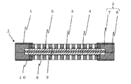
図1は本発明の燃料電池用容器およびそれを用いた燃料電池について実施の形態の一例を示す断面図である。図1において、1は燃料電池、2は燃料電池用容器、3は電解質部材、4は第1電極、5は第2電極、6は基体、7は蓋体、8は第1流体流路、9は第2流体流路、10は第1配線導体、11は第2配線導体である。 FIG. 1 is a cross-sectional view showing an example of an embodiment of a fuel cell container and a fuel cell using the same according to the present invention. In FIG. 1, 1 is a fuel cell, 2 is a fuel cell container, 3 is an electrolyte member, 4 is a first electrode, 5 is a second electrode, 6 is a base, 7 is a lid, 8 is a first fluid flow path, 9 is a second fluid flow path, 10 is a first wiring conductor, and 11 is a second wiring conductor.
また、図2は図1の本発明の燃料電池用容器およびそれを用いた燃料電池における第1流体流路または第2流体流路の開口の周辺を示す断面図である。図2において符号は図1と同様であり、12は気孔である。
Also, FIG. 2 is a sectional view showing the periphery of the first fluid flow path or opening of the second fluid flow path in the fuel cell container and a fuel cell using the same of the present invention in FIG. In FIG. 2, the reference numerals are the same as those in FIG. 1, and 12 is a pore.
本発明における電解質部材3は、例えばイオン導電膜(交換膜)の両主面上に、下側主面に形成された第1電極4および上側主面に形成された第2電極5にそれぞれ対向するように、アノード側電極となる燃料極(図示せず)と、カソード側電極となる空気極(図示せず)とが一体的に形成されている。そして、電解質部材3で発電された電流を第1電極4、第2電極5へ流し、外部へ取り出すことができるものとなっている。
The
このような電解質部材3のイオン導電膜(交換膜)は、パーフルオロカーボンスルフォン酸樹脂、例えば商品名「ナフィオン」(デュポン社製)等のプロトン伝導性のイオン交換樹脂により構成されている。また、燃料極および空気極は、多孔質状態のガス拡散電極であり、多孔質触媒層とガス拡散層の両方の機能を兼ね備えるものである。これらの燃料極および空気極は、白金、パラジウムあるいはこれらの合金等の触媒を担持した導電性微粒子、例えばカーボン微粒子をポリテトラフルオロエチレンのような疎水性樹脂結合剤により保持した多孔質体によって構成されている。
Such an ion conductive film (exchange membrane) of the
電解質部材3の下側主面の第1電極4および上側主面の第2電極5は、白金や白金−ルテニウム等の触媒微粒子の付いた炭素電極を電解質部材3上にホットプレスする方法、または、白金や白金−ルテニウム等の触媒微粒子の付いた炭素電極材料と電解質材料を分散した溶液との混合物を電解質上に塗布または転写する方法等により形成される。
The
燃料電池用容器2は、凹部を有する基体6と蓋体7とから成り、電解質部材3を凹部の内部に搭載して気密に封止する役割を持ち、酸化アルミニウム(Al2O3)質焼結体、ムライト(3Al2O3・2SiO2)質焼結体、炭化珪素(SiC)質焼結体、窒化アルミニウム(AlN)質焼結体、窒化珪素(Si3N4)質焼結体、ガラスセラミックス焼結体等のセラミックス材料で形成されている。
The
なお、ガラスセラミックス焼結体はガラス成分とフィラー成分とから成るが、ガラス成分としては、例えばSiO2−B2O3系,SiO2−B2O3−Al2O3系,SiO2−B2O3−Al2O3−MO系(但し、MはCa,Sr,Mg,BaまたはZnを示す),SiO2−Al2O3−M1O−M2O系(但し、M1およびM2は同一または異なってCa,Sr,Mg,BaまたはZnを示す),SiO2−B2O3−Al2O3−M1O−M2O系(但し、M1およびM2は上記と同じである),SiO2−B2O3−M3 2O系(但し、M3はLi,NaまたはKを示す),SiO2−B2O3−Al2O3−M3 2O系(但し、M3は上記と同じである),Pb系ガラス,Bi系ガラス等が挙げられる。 The glass ceramic sintered body includes a glass component and a filler component. Examples of the glass component include SiO 2 —B 2 O 3 , SiO 2 —B 2 O 3 —Al 2 O 3 , and SiO 2 —. B 2 O 3 —Al 2 O 3 —MO system (M represents Ca, Sr, Mg, Ba or Zn), SiO 2 —Al 2 O 3 —M 1 O—M 2 O system (M 1 and M 2 are the same or different and represent Ca, Sr, Mg, Ba or Zn), SiO 2 —B 2 O 3 —Al 2 O 3 —M 1 O—M 2 O system (provided that M 1 and M 2 is the same as above), SiO 2 —B 2 O 3 —M 3 2 O system (where M 3 represents Li, Na or K), SiO 2 —B 2 O 3 —Al 2 O 3 — M 3 2 O-based (where M 3 is the same as above), Pb-based glass And Bi-based glass.
また、フィラー成分としては、例えばAl2O3,SiO2,ZrO2とアルカリ土類金属酸化物との複合酸化物、TiO2とアルカリ土類金属酸化物との複合酸化物、Al2O3およびSiO2から選ばれる少なくとも1種を含む複合酸化物(例えばスピネル,ムライト,コージェライト)等が挙げられる。 Examples of the filler component include a composite oxide of Al 2 O 3 , SiO 2 , ZrO 2 and an alkaline earth metal oxide, a composite oxide of TiO 2 and an alkaline earth metal oxide, Al 2 O 3. And composite oxides containing at least one selected from SiO 2 (for example, spinel, mullite, cordierite) and the like.
燃料電池用容器2は、凹部を有する基体6と蓋体7とから成り、基体6の凹部の周囲に凹部を覆って蓋体7を取着することによって凹部を気密に封止するため、半田や銀ろう等の金属接合材料での接合、エポキシ樹脂等の樹脂材料での接合、凹部の周囲の上面に鉄合金等で作られたシールリング等を接合してシームウェルドやエレクトロンビームやレーザ等で溶接する方法等によって、蓋体7が基体6に取着される。なお、蓋体7にも基体6と同様の凹部を形成しておいてもよい。
The
基体6および蓋体7は、それぞれ厚みを薄くし、燃料電池1の低背化を可能とするためには、機械的強度である曲げ強度が200MPa以上であることが好ましい。
In order to reduce the thickness of the
基体6および蓋体7は、例えば相対密度が95%以上の緻密質からなる酸化アルミニウム質焼結体で形成されていることが好ましい。その場合であれば、例えば、まず酸化アルミニウム粉末に希土類酸化物粉末や焼結助剤を添加、混合して、酸化アルミニウム質焼結体の原料粉末を調製する。次いで、この酸化アルミニウム質焼結体の原料粉末に有機バインダおよび分散剤を添加、混合してペースト化し、このペーストからドクターブレード法によって、あるいは原料粉末に有機バインダを加え、プレス成形、圧延成形等によって、所定の厚みのグリーンシートを作製する。そして、このグリーンシートに対して、金型による打ち抜き法、マイクロドリルによる穴あけ法、レーザ光照射よる穴あけ法等により、第1流体流路8および第2流体流路9としての貫通穴、ならびに第1配線導体10および第2配線導体11を配設するための貫通孔を形成する。なお、第1流体流路8および第2
流体流路9は、金型による打ち抜きやプレス成形等により表面や内部に形成された溝であってもよい。
The
The
基体6および蓋体7を構成するセラミックス材料に酸化アルミニウム質焼結体を用いる場合には、第1配線導体10および第2配線導体11は、酸化を防ぐために、タングステンおよび/またはモリブデンで形成されているのが好ましい。その場合であれば、例えば、無機成分としてタングステンおよび/またはモリブデン粉末100質量部に対して、Al2O3を3〜20質量部,Nb2O5を0.5〜5質量部の割合で添加してなる導体ペーストを調製する。この導体ペーストをグリーンシートの貫通孔内に充填して、貫通導体としてのビア導体を形成する。
When an aluminum oxide sintered body is used as the ceramic material constituting the
これらの導体ペースト中には、基体6や蓋体7のセラミックスとの密着性を高めるために、酸化アルミニウム粉末や、基体6や蓋体7を形成するセラミックス成分と同一の組成物粉末を、例えば0.05〜2体積%の割合で添加することも可能である。
In these conductor pastes, in order to improve the adhesion of the
なお、基体6や蓋体7の表層および内層への第1配線導体10および第2配線導体11の形成は、貫通孔へ導体ペーストを充填してビア導体を形成する前後あるいはそれと同時に、同様の導体ペーストをグリーンシートに対しスクリーン印刷、グラビア印刷等の方法で所定パターンに印刷塗布して形成する。
The formation of the
その後、導体ペーストを印刷し充填した所定枚数のシート状成形体を位置合わせして積層圧着した後、この積層体を、例えば非酸化性雰囲気中にて、焼成最高温度が1200〜1500℃の温度で焼成して、目的とするセラミックスの基体6や蓋体7および第1配線導体10、第2配線導体11を得る。
Then, after aligning and laminating and pressure-bonding a predetermined number of sheet-like molded bodies filled with conductive paste, the laminated body is heated at a maximum firing temperature of 1200 to 1500 ° C., for example, in a non-oxidizing atmosphere. To obtain the target
また、第1配線導体10、第2配線導体11は、電解質部材3にて電気化学的に生成された電気を効率よく外部に取り出すという観点からは、比電気抵抗が0.1ミリΩcm以
下であることが好ましい。このような材料としては、銀,銀系の金属,銅,銅系の金属等が挙げられる。例えば、基体6や蓋体7をガラスセラミックス焼結体で形成し、第1および第2配線導体11を銅や銅系の金属とすることにより、基体6や蓋体7を第1および第2配線導体11と同時焼成して低抵抗の配線導体を容易に形成することができる。
The
また、燃料電池用容器2に形成された第1配線導体10、第2配線導体11を含むすべての導体の体積は、燃料電池用容器2の体積の0.5%以上であるのがよい。これにより、燃料電池用容器2に形成された導体の抵抗が小さくなり、電解質部材3にて電気化学的に生成された電気を効率よく外部に取り出すことができる。
Further, the volume of all conductors including the
また、基体6や蓋体7の少なくとも一方に、半田やロウ付け等により外部接続用端子(図示せず)が接合されてもよい。外部接続用端子は、電子機器の主となる電子回路を形成するためのマザーボード等と良好な電気接続が行なえる形状であることが望ましい。このような形状としては、例えば、電子機器の主となる電子回路に端子同士を接触や挿入することにより簡単に電気的,機械的に接続することができるような棒状、鉤状、円錐状等のものが用いられる。なお、電子機器の主となる電子回路のうち、このような外部接続用端子が接続される部位には、この外部接続用端子に対応した勘合部(穴など)を設けておくことが好ましい。さらに、外部接続用端子を基体6や蓋体7の側面に配置することで、電子機器の低背化を行なうことができる。
Further, an external connection terminal (not shown) may be joined to at least one of the
また、セラミックスから成る基体6や蓋体7は、その厚みを0.2mm以上とすることが好ましい。厚みが0.2mm未満では、強度が低下しがちなため、基体6に蓋体7を取着したときに発生する応力により、基体6および蓋体7に割れ等が発生しやすくなる傾向がある。他方、厚みが5mmを超えると、薄型化、低背化が困難となるため、小型携帯機器に搭載する燃料電池1としては不適切となり、また、熱容量が大きくなるため、電解質部材3の電気化学反応条件に相当する適切な温度にすばやく設定することが困難となる傾向がある。
Moreover, it is preferable that the base |
第1配線導体10および第2配線導体11は、それぞれ電解質部材3の第1電極4および第2電極5に電気的に接続されて、電解質部材3で発電された電流を燃料電池用容器2の外部へ取り出すための導電路として機能する。
The
第1配線導体10は、基体6の凹部の底面の電解質部材3の第1電極4に対向する第1流体流路8の開口の周辺の電解質部材3の第1電極4が接触する部位の面の全域に一端が当接するように形成されている。これにより、電解質部材3の第1電極4と第1配線導体10との接触面積を大きくすることができることから、電気抵抗の増大化および接触不良を有効に抑えることができ、高い発電効率を有した燃料電池1を提供することができる。
The
また、第1配線導体10は、第1電極4に接触させやすいように基体6の凹部の底面より10μm以上高くするように形成するのが望ましい。この高さを得るためには、前述したように導体ペーストを印刷塗布して形成する際に、印刷条件を厚くするように設定すればよい。また、第1配線導体10は第1電極4に対向させて複数配置し、第1配線導体10による電気損失を減少させることが望ましく、第1配線導体10の基体6の貫通部についてはφ(直径)50μm以上の径とすることが好ましい。
Further, the
また、第2配線導体11は、蓋体7の下面の電解質部材3の第2電極5に対向する第2流体流路9の開口の周辺の電解質部材3の第2電極5が接触する部位の面の全域に一端が配設され、他端が蓋体7の外面に導出されて形成されている。これにより、電解質部材3の第2電極5と第2配線導体11との接触面積を大きくすることができることから、電気抵抗の増大化および接触不良を有効に抑えることができ、高い発電効率を有した燃料電池1を提供することができる。
In addition, the second wiring conductor 11 is a part of the portion where the
このような第2配線導体11も、第1配線導体10と同様に、蓋体7と一体的に形成され、第2配線導体11を第2電極5に接触させやすいように蓋体7の凹部の底面より、10μm以上高くするように形成するのが望ましい。この高さを得るためには、前述したように導体ペーストを印刷塗布して形成する際に、印刷条件を厚くするように設定すればよい。また、第2配線導体11は第2電極5に対向させて複数配置し、第2配線導体11による電気損失を減少させることが望ましく、第2配線導体11の蓋体7の貫通部についてはφ50μm以上の径とすることが好ましい。
Similar to the
これら第1配線導体10および第2配線導体11および外部接続用端子には、その露出する表面に良導電性で、かつ、耐蝕性およびロウ材との濡れ性が良好なニッケル、銅、金、白金およびパラジウム等の金属をメッキ法により被着させておくと、これらの導体と電子機器の主となる電子回路を形成するためのマザーボード等との電気的接続を良好とすることができる。
The
そして、これら第1および第2配線導体10,11と第1および第2電極4,5との電気的な接続は、基体6と蓋体7とで電解質部材3を挟み込むことによって、第1および第2配線導体10,11と第1および第2電極4,5とを圧着接触させて電気的接続させる等の構成によって行なえばよい。
The first and
また、第1電極4および第2電極5に対向する基体6の凹部の底面および蓋体7の下面には、それぞれ第1流体流路8および第2流体流路9が配置されており、第1流体流路8は基体6の外面にかけて、また第2流体流路9は蓋体7の外面にかけて形成されている。これら第1および第2流体流路8,9は、それぞれ基体6や蓋体7に形成した貫通穴あるいは溝によって、燃料ガス例えば水素に富む改質ガス、あるいは酸化ガス例えば空気等の、電解質部材3へ供給される流体の通路として、あるいは反応で生成される水等の、反応後に電解質部材3から排出される流体の通路として設けられている。
In addition, a first
第1流体流路8および第2流体流路9として基体6および蓋体7に形成される貫通穴あるいは溝は、電解質部材3に均等に燃料ガスや酸化ガス等の流体が供給されるように、燃
料電池1の仕様に応じて、貫通穴の径や数、あるいは溝の幅、深さ、配置を決めればよい。
The through holes or grooves formed in the
本発明の燃料電池用容器2および燃料電池1においては、第1流体流路8および第2流体流路9は、好適には、電解質部材3に均一な圧力で流体を流すため、φ0.1mm以上の穴径とし、間隔を一定にして配置するようにするとよい。
In the
このように電解質部材3の第1電極4が形成された下側主面に対向させて第1流体流路8を、第2電極5が形成された上側主面に対向させて第2流体流路9を形成したことによって、電解質部材3の下側および上側主面と第1および第2流体流路8,9との間で流体がやりとり可能となり、その流体がそれぞれの流路を通して供給あるいは排出されることとなる。そして、例えば流体としてガスを供給する場合であれば、電解質部材3の第1電極4および第2電極5にそれぞれ供給されるガス分圧が下がることをなくすことができ、所定の安定した出力電圧を得ることができる。さらに、供給されるガス分圧が安定するため、燃料電池1の内部圧力が均一化され、その結果、電解質部材3に生じる熱応力を抑制することができるので、燃料電池1の信頼性を向上させることができる。
In this way, the first
そして、本発明においては、第1配線導体10および第2配線導体11は、凹部の底面の第1流体流路8の開口の周辺または蓋体7の下面の第2流体流路9の開口の周辺の第1電極4または第2電極5と接触する部位の全域に一端が当接するように形成されており、かつ第1流体流路8および第2流体流路9の開口の周辺が、第1流体流路8と第1電極4とを連通する気孔12を有する多孔質および第2流体流路9と第2電極5とを連通する気孔12を有する多孔質になっている。これにより、第1流体流路8や第2流体流路9から流体が直接電解質部材3へ供給されるだけでなく、第1配線導体10や第2配線導体11の多孔質の連通する気孔12を通じて流体が電解質部材3へ供給されるので、第1電極4や第2電極5に空気および燃料ガスが接触する面積を大きくすることができ、空気や燃料ガスの電気化学反応を促進させ、発電効率をより高いものとすることができる。
In the present invention, the
さらに、気孔径や気孔率を調製することで、水素ガス,メタノール等の燃料や酸素ガス等の酸化剤ガスの種類や供給方式に応じて、第1電極4や第2電極5に供給される燃料や酸化剤ガスの供給速度を容易にかつ精度良く調整することが可能となり、発電効率を非常に高いものとすることができる。
Furthermore, by, prepare pore diameter and porosity, hydrogen gas, depending on the type and supply method of the oxygen-containing gas such as a fuel and oxygen gas, such as methanol, is supplied to the
このような多孔質の第1配線導体10、または多孔質の第2配線導体11は以下のようにして作製される。例えば、第1配線導体10または第2配線導体11がタングステンおよび/またはモリブデンから成る場合には、タングステン粉末またはモリブデン粉末と、エチルセルロースやテルピネオール等の溶剤が混合されたペーストに、これらの溶剤には溶解せず、かつ、焼成の際に揮発するテレフタル酸等の有機物を添加し混合することによって気孔形成用導体ペーストを得る。そして、この気孔形成用導体ペーストを、基体6や蓋体7となるセラミックグリーンシートの所定位置に、前述の燃料電池用容器の作製方法と同様な方法で印刷および積層圧着した後に焼成することによって、第1配線導体10または第2配線導体11を、第1流体流路8または第2流体流路9の開口の周辺が第1流体流路8と第1電極4とを連通する気孔12、または、第2流体流路9と第2電極5とを連通する気孔12を有する多孔質となるようにすることができる。
Such a porous
また、本発明の燃料電池用容器2において、基体6および蓋体7は、多孔質の第1配線導体10に接する部分、または多孔質の第2配線導体11に接する部分が、第1流体流路8と第1配線導体10とを連通する気孔12を有する多孔質に、または第2流体流路9と第2配線導体11とを連通する気孔12を有する多孔質になっている。これにより、第1配線導体10や第2配線導体11の多孔質の連通する気孔12だけでなく、基体6や蓋体7の多孔質の連通する気孔12を通じて流体が電解質部材3へ供給されるので、より良好に気孔12を通じて流体が電解質部材3へ供給することができ、発電効率をより向上させることができる。
Further, in the
また、このような多孔質は3次元網目構造であり、機械的特性において等方的な特性を有することから、基体6や蓋体7の第1配線導体10や第2配線導体11が配設された部位における機械的特性や流体の透過特性における信頼性を高くすることができる。
In addition, since such a porous material has a three-dimensional network structure and isotropic in mechanical properties, the
このような、第1流体流路8と第1配線導体10とを連通する気孔12、または、第2流体流路9と第2配線導体11とを連通する気孔12を有する基体6または蓋体7は以下のようにして作製される。例えば、基体6または蓋体7が酸化アルミニウム質焼結体から成る場合には、前述の基体6または蓋体7の作製法と同様に、まず酸化アルミニウム粉末に希土類酸化物粉末や焼結助剤を添加、混合して、酸化アルミニウム質焼結体の原料粉末を調製する。次いで、この酸化アルミニウム質焼結体の原料粉末に有機バインダおよび分散剤を添加、混合してペースト化する。
Such a
次にこのペーストに気孔形成用材料として、例えば、アクリル樹脂、ワックス、ゴム等の加熱によって焼失または溶出するもの、または、熱または酸等によって溶出または分解するSn、Pb等の金属を添加し混合する。 Next, as a pore-forming material, for example, an acrylic resin, wax, rubber or the like that is burned out or eluted by heating, or a metal such as Sn or Pb that is eluted or decomposed by heat or acid is added and mixed. To do.
なお、気孔形成用材料は、粒径や体積、およびこれらの分布が均等であり、所望の気孔径や気孔率に調製が容易であるという観点からは、球状であることが好ましい。
Incidentally, the pore-forming material, the particle size and volume, and are equivalent of these distributions, from the viewpoint that it is easy to made adjusted to the desired pore size and porosity, it is preferably spherical.
このようにして得た気孔形成用材料を混合したペーストを、ドクターブレード法等によって、所定厚みの気孔形成用材料含有グリーンシートを作製する。そして、この気孔形成用材料含有グリーンシートを、金型やレーザ等を用いて所定形状に加工する。 A pore-forming material-containing green sheet having a predetermined thickness is prepared from the paste obtained by mixing the pore-forming materials thus obtained by a doctor blade method or the like. Then, the pore-forming material-containing green sheet is processed into a predetermined shape using a mold, a laser, or the like.
以上のようにして得た気孔形成用グリーンシートを、基体6や蓋体7の所定位置に、前述の燃料電池用容器の作製方法と同様な方法で積層圧着し、所定位置に気孔形成用導体ペーストを印刷塗布した後に焼成することによって、基体6または蓋体7を、第1流体流路8と第1配線導体10とを連通する気孔12、または、第2流体流路9と第2配線導体11とを連通する気孔12を有する多孔質とすることができる。
The pore-forming green sheet obtained as described above is laminated and pressure-bonded to predetermined positions of the
なお、図2のように、第1電極4に当接した第1配線導体10および第2電極5に当接した第2配線導体11が多孔質になっているとともに、基体6および蓋体7の第1流体流路8または第2流体流路9の開口の周辺が多孔質になっており、第1流体流路8または第2流体流路9の開口の周辺が緻密質の場合に比べて、電解質部材3へ供給される流体の量がより一層多くなることから、空気および燃料ガスの電気化学反応を促進させ、発電効率をより高いものとすることができる。
As shown in FIG. 2, the
また、第1流体流路8や第2流体流路9の内壁は吸湿材が被着されていることが好ましい。電解質部材3において電気化学反応で生成した水蒸気や水等をこの吸湿材により吸収し除去することができるため、空気の流路となる第1および第2流体流路8,9の閉塞を効果的に防止することができる。そのため、第1および第2電極4,5の電極の表面が水(H2O)で覆われることを効果的に防止することができ、第1および第2流体流路8,9を通して大気中から酸化ガスとして空気を効果的に供給することができるため、電解質部材3での電気化学反応を促進することができ高効率な発電を行なうことが可能となる。
Moreover, it is preferable that the inner wall of the first
前記吸湿材としては、シリカゲル、アルミナ、白土、活性炭、紙、木紛等の水を吸収しやすい材料を用いればよいが、特にシリカゲル、アルミナ、白土等の無機粉末は、粉砕等により粉末の大きさを調製することによって水の吸収面積を調節しやすいため、所望の吸湿特性を得やすい点で好ましいものである。 The pre-Symbol absorbent, silica gel, alumina, clay, activated carbon, paper, may be used material that easily absorbs water wood紛等, in particular silica gel, alumina, inorganic powder clay or the like, a powder by milling or the like since easily adjust the absorption area of water by steel size adjustment, it is preferred in terms of easy to obtain the desired hygroscopic properties.
吸湿材を第1流体流路8や第2流体流路9の内壁に被着させる場合、第1および第2流体流路8,9を通して大気中から酸化ガスとして空気の流れの均一性を保つうえで、全ての第1流体流路8や第2流体流路9に吸湿材を被着するのがよく、また、吸湿材の厚みは、酸化ガスとしての空気を供給する際に圧力損失の影響を小さくする必要があるため、例えば、第1および第2流体流路8,9に被着させる場合には、これらの横断面での開口面積に対して10%以下の面積となる厚みが好ましい。
When the hygroscopic material is applied to the inner walls of the first
さらに、空気の流れにより吸湿材からの水分の蒸発を促進するためにも、第1流体流路8や第2流体流路9の内壁全体に吸湿材を被着することが好ましい。これにより、本発明の燃料電池用容器2および燃料電池1を、例えば携帯用の直接形メタノール燃料電池(DMFC)等の小型タイプのものに使用する場合、例えばメタノール10mlで数十時間の運転が可能となるとともに、その際の水の生成量としてもメタノール1gの消費に対して1mlと微量となる。そのため、吸湿材が吸収した水は、ファンを用いた送風によって十分蒸発させることが可能な水分量となり、連続運転に差し支えないものとなる。
Further, in order to promote the evaporation of moisture from the hygroscopic material by the air flow, it is preferable to apply the hygroscopic material to the entire inner walls of the first
以上の構成により、図1に示すような、電解質部材3を収納可能な、小型で堅牢な燃料電池用容器2が得られ、高効率制御が可能な本発明の燃料電池1が得られる。
With the above configuration, a small and robust
次に、上記の燃料電池1を電源として有する本発明の電子機器について説明する。
Next, the electronic apparatus of the present invention having the
本発明の電子機器は電源として上記のような燃料電池1を有していることから、以上のような本発明の燃料電池用容器2による特長を備えた、小型,低背で、かつ長期にわたり安定して作動させることのできる安全性や利便性に優れた電子機器を得ることができる。
Since the electronic device of the present invention has the
また、電源として有している燃料電池1に、基体6および蓋体7の少なくとも一方に、外部接続用端子(正極端子および負極端子)を具備させると、電子機器の回路基板に容易に電気的接続が可能となり、着脱が自在となる。そのため、特殊な安全設備を備えた施設等によることなく、容易に燃料電池1を新しいものと取り替えることができ、電子機器の利便性を高いものとすることができる。
Further, when the
さらに、燃料電池用容器2の基体6の内部にメタライズ法等により金属層を種々の形状,電気特性で形成することができるので、基体6の内部に、抵抗やキャパシタンスやインダクタンス等として機能する電子回路素子を形成することができる。従って、例えば、燃料電池1に平行して、大容量のキャパシタを形成することで、燃料電池1から出力される電流が不足する状態となった場合、不足する電流分が補填されて目標出力電流に応じた電流供給を確保することが可能である。また、昇圧回路を形成することができるため、電子機器に必要な電圧を確保することが可能である。
Furthermore, since a metal layer can be formed in various shapes and electrical characteristics by the metallization method or the like inside the
なお、このように基体6の内部に、抵抗やキャパシタンスやインダクタンスを形成する場合には、基体6はガラスセラミックスから成ることが好ましい。
In addition, when forming resistance, a capacitance, and an inductance in the inside of the base |
そして、本発明の電子機器としては、具体的には携帯電話,PDA(Personal Digital Assistants),デジタルカメラやビデオカメラ,ゲーム機などの玩具等の携帯型電子機器、また、ノート型PC(パーソナルコンピュータ)をはじめとするポータブルなプリンター,ファクス,テレビ,通信機器,オーディオビデオ機器,扇風機等の各種家電製品,電動工具等の電子機器がある。 Specifically, the electronic device of the present invention includes portable electronic devices such as mobile phones, PDAs (Personal Digital Assistants), toys such as digital cameras, video cameras, and game machines, and notebook PCs (personal computers). ) And other portable printers, fax machines, televisions, communication equipment, audio-video equipment, electric appliances such as electric fans, and electronic equipment such as electric tools.
これらの電子機器は、近年、液晶表示装置等を用いた動画表示の機能を付加したものが使用されるようになってきている。このような動画表示は電源の消費が非常に大きいことから、従来の蓄電池を用いた電子機器では短時間で動作不能となるのに対し、本発明の電子機器は非常に長時間の電源を供給できる燃料電池1を搭載しており、動画表示を行なっても長時間の動作が可能となる。
In recent years, these electronic devices have been added with a function of displaying a moving image using a liquid crystal display device or the like. Such a video display consumes a large amount of power, so that an electronic device using a conventional storage battery cannot be operated in a short time, whereas the electronic device of the present invention supplies a very long time power. The
例えば携帯電話の場合、中央処理装置(CPU)と、制御部と、ランダムアクセスメモリ(RAM)と、リードオンメモリ(ROM)と、使用者により操作されたデータをCPUに入力する入力部と、アンテナと、アンテナで受信された信号を復調して制御部に供給すると共に、制御部から供給された信号を変調してアンテナより送信させる無線部と、制御部からの鳴動信号に基づき鳴音するスピーカと、制御部からの制御により点灯、消灯あるいは点滅する発光ダイオード(LED)と、制御部から信号により情報の表示を行なう表示部と、制御部からの駆動信号により振動するバイブレータと、使用者の音声を音声信号に変換して制御部へ伝達し、制御部からの音声信号は音声に変換して出力する送受話部と、各部に電源を供給する電源部とから構成されており、その電源部に本発明の燃料電池1および燃料電池用容器2が組み込まれることによって、燃料電池1および燃料電池用容器2が、コンパクト性、簡便性および安全性に優れ、燃料の均等供給および高効率な電気接続による長時間の電源供給が可能となることから、携帯電話の小型、低背化および軽量化が可能となる。
For example, in the case of a mobile phone, a central processing unit (CPU), a control unit, a random access memory (RAM), a read-on memory (ROM), an input unit for inputting data operated by a user to the CPU, The antenna, the signal received by the antenna is demodulated and supplied to the control unit, the radio unit that modulates the signal supplied from the control unit and transmitted from the antenna, and the sound is generated based on the ringing signal from the control unit A speaker, a light emitting diode (LED) that is turned on, off, or blinking under the control of the control unit, a display unit that displays information by a signal from the control unit, a vibrator that vibrates by a drive signal from the control unit, and a user The voice signal from the control unit is transmitted to the control unit, the voice signal from the control unit is converted into voice and output, and the power source that supplies power to each unit The
また、近時の携帯電話が小型化、低背化の面では十分であることを考慮すると、このように燃料電池1を小型、低背化することよって生じたスペースに、例えば、カメラやビデオ等の電話機能以外の機能を有する電子部品を新たに組み込むことが可能となり、更なる多機能化を行なうことができる。
Also, considering that recent mobile phones are sufficient in terms of miniaturization and low profile, in the space generated by miniaturizing and reducing the height of the
また、新たに電子部品を組み込む替わりに、衝撃吸収材や衝撃防止部材等を主要な電子回路を保護するようにして設けることもできる。この場合、落下等により携帯電話本体に衝撃が加わった際の耐衝撃性や、雨中での使用等の際の防水性などを従来よりも強固にし得る構造とすることもできる。 Further, instead of newly incorporating electronic components, an impact absorbing material, an impact preventing member or the like can be provided so as to protect the main electronic circuit. In this case, it is also possible to have a structure that can make the impact resistance when a shock is applied to the mobile phone main body due to dropping or the like, the waterproofness when used in rain, etc. stronger than before.
また、携帯電話本体内部の電気回路部を小さくすることが可能となることによって、携帯電話本体の外形への制約が少なくなり、例えば、携帯電話を老人や子供にとって握りやすい形状とすること等の意匠性に優れた外形状とすることが可能となる。 In addition, by making it possible to reduce the size of the electric circuit inside the mobile phone body, there are fewer restrictions on the external shape of the mobile phone body, for example, making the mobile phone a shape that is easy for an elderly person or child to grip. It becomes possible to make the outer shape excellent in design.
また、電源部の構造を上述のように燃料電池1および燃料電池用容器2が着脱自在となる構造とした場合には、予備の燃料電池1および燃料電池用容器2を準備しておけば、電池切れ等が発生した場合に容易に予備の燃料電池1および燃料電池用容器2に交換、あるいは、燃料電池1を取り出して、燃料の補給や交換をすることができるので、継続して通話等を行うことができ、従来の蓄電池を電源として使用するもの等に比べて利便性に優れるものとなる。
Further, in the case where the structure of the power source is a structure in which the
また、交換された(使用済みの)燃料電池1は、燃料を補給することによりすぐに再利用できるので、充電に比べて使い勝手がよく、また資源を有効利用することも可能なものとなる。また、自然災害等による長期にわたる停電等の緊急時や屋外においても使用が可能となるという利点がある。
In addition, since the replaced (used)
また、ノート型PC(パーソナルコンピュータ)の場合、パーソナルコンピュータ本体と、パーソナルコンピュータ本体に所定のデータを入力するためのキーボードとを納めた第1の筐体と、キーボードにより入力されたデータあるいはパーソナルコンピュータ本体により処理されたデータを表示するためのディスプレイを納めた第2の筐体とを備え、第2の筐体が第1の筐体に開閉可能に取り付けられており、さらに各部に電源を供給する電源部を第1の筐体に設けるという基本構成から成り、その電源部に燃料電池1および燃料電池用容器2が組み込まれる。この場合、前述の携帯電話と同様に、本発明の電子機器に組み込まれる燃料電池1および燃料電池用容器2が、コンパクト性、簡便性および安全性に優れ、燃料の均等供給および高効率な電気接続による長時間の電源供給が可能となることから、ノート型PC(パーソナルコンピュータ)本体の小型、低背化、軽量化および多機能化が可能となるとともに、ディスプレイの大型化や高解像度化に対応して、大きな電流を安定して、長期にわたって供給することも可能で、ディスプレイが見やすく、かつ携帯の際の重量や容積上の負担も少ない等の利便性の高いノート型PC(パーソナルコンピュータ)とすることができる。
In the case of a notebook PC (personal computer), a personal computer main body, a first housing containing a keyboard for inputting predetermined data to the personal computer main body, data input by the keyboard, or a personal computer And a second housing containing a display for displaying data processed by the main body, the second housing is attached to the first housing so as to be openable and closable, and power is supplied to each part. The power supply unit is configured to be provided in the first casing, and the
また、電源部の構造を燃料電池1および燃料電池用容器2が着脱自在となる構造とした場合には、予備の本発明の燃料電池1および燃料電池用容器2を準備しておけば、屋外や旅客機等の移動体内等の2次電池のみで使用するような状況において、従来に比べ飛躍的に長時間の電源供給が可能となるという利点がある。また、このように公共の場で使用する場合にも、安全性に優れることから、制約を受けることなく使用することが可能な、極めて利便性に優れたものとなる。
If the
なお、本発明は以上の実施の形態の例に限定されるものではなく、本発明の要旨を逸脱しない範囲であれば、種々の変更を行なっても何ら差し支えない。例えば、第1流体流路8や第2流体流路9については、燃料電池1全体を薄型化するため、基体6または蓋体7の側面からの流入口を設けるようにしてもよい。これによれば、特に携帯電子機器用として小型化を成す上で有効となる。さらに、第1および第2配線導体10,11については、基体6および蓋体7の外面に導出される他端を、それぞれ同じ側の側面に引き出すように配設してもよい。これによれば、燃料電池の一方側面に配線や流路等をまとめることができ、小型化と外部への接合部の保護とが容易となり、信頼性の高い設計が可能となるとともに、長期間安定した作動が可能な燃料電池となる。
It should be noted that the present invention is not limited to the embodiments described above, and various modifications can be made without departing from the scope of the present invention. For example, the first
また、基体6の凹部の内部には、複数の電解質部材3を収容してこれらを第1および第2配線導体10,11により電気的に接続して全体として高電圧あるいは大電流の出力を得るようにしてもよい。
A plurality of
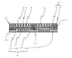
また、図3に本発明の燃料電池用容器および燃料電池の実施の形態の他の例を断面図で示すように、第1流体流路8’および第2流体流路9’の少なくとも一方を、基体6’の凹部の底面または蓋体7’の下面に電解質部材3の下側主面または上側主面に対向するように溝状の開口が葛折状に形成された開口部13と、開口部13から基体6’または蓋体7’の外面にかけて形成された流体の導入部15と、他の開口部13または連結部14から基体6’または蓋体7’の外面にかけて形成された流体の排出部16とから構成してもよい。
FIG. 3 is a sectional view showing another example of the fuel cell container and the fuel cell according to the present invention. At least one of the first
これにより、平面に並んだ複数の電解質部材3への燃料ガスや酸化剤ガスの供給や排出が、基体6’または蓋体7’の内部に形成された3次元的な流体流路である連結部14、導入部15、排出部16を用いて、外部に漏れることなく気密に行なうことができるため、安全でかつ電気化学的に良好に、効率的に取り出すことができる燃料電池1’を提供することができる。
Thereby, the supply and discharge of the fuel gas and the oxidant gas to the plurality of
また、複数の凹部を有する基体6’の各凹部に電解質部材3を収容し、隣接する凹部の端部間にわたって第3配線導体17を配設し、複数の電解質部材3の第1電極4の間または第1電極4と第2電極5との間を電気的に接続し、両端となる位置に配置された電解質部材3に全体としての出力を取り出すように第1配線導体10’および第2配線導体11’をそれぞれに電気的に接続するようにしてもよい。
In addition, the
これにより、複数の電解質部材3の間の流体流路を、連結部14、導入部15、および排出部16で3次元的に自由に形成し、組み合わせることができ、電解質部材3の配置に応じて、燃料供給の一様性を保ちつつ、高密度に流体流路を形成することが可能となり、燃料電池1’の低背化,小型化が可能となる。
Thereby, the fluid flow path between the plurality of
さらに、第1〜第3配線導体10’,11’,17により3次元的に自由に配線ができるため、複数の電解質部材3を任意に直列接続または並列接続することが可能となる。その結果、全体の出力電圧および出力電流を効率よく調整することが可能となるため、電解質部材3にて電気化学的に生成された電気を良好に外部に取り出すことができる燃料電池用容器2’および燃料電池1’となる。
Furthermore, since the first to
なお、本発明は以上の実施の形態の例に限定されるものではなく、本発明の要旨を逸脱しない範囲で種々の変更を加えることは何ら差し支えない。 In addition, this invention is not limited to the example of the above embodiment, A various change may be added in the range which does not deviate from the summary of this invention.
1、1’:燃料電池
2、2’:燃料電池用容器
3:電解質部材
4:第1電極
5:第2電極
6、6’:基体
7、7’:蓋体
8、8’:第1流体流路
9、9’:第2流体流路
10、10’:第1配線導体
11、11’:第2配線導体
12:気孔
DESCRIPTION OF
Claims (3)
Priority Applications (1)
| Application Number | Priority Date | Filing Date | Title |
|---|---|---|---|
| JP2004084277A JP4828799B2 (en) | 2004-03-23 | 2004-03-23 | Fuel cell container, fuel cell and electronic device |
Applications Claiming Priority (1)
| Application Number | Priority Date | Filing Date | Title |
|---|---|---|---|
| JP2004084277A JP4828799B2 (en) | 2004-03-23 | 2004-03-23 | Fuel cell container, fuel cell and electronic device |
Publications (2)
| Publication Number | Publication Date |
|---|---|
| JP2005276464A JP2005276464A (en) | 2005-10-06 |
| JP4828799B2 true JP4828799B2 (en) | 2011-11-30 |
Family
ID=35175920
Family Applications (1)
| Application Number | Title | Priority Date | Filing Date |
|---|---|---|---|
| JP2004084277A Expired - Fee Related JP4828799B2 (en) | 2004-03-23 | 2004-03-23 | Fuel cell container, fuel cell and electronic device |
Country Status (1)
| Country | Link |
|---|---|
| JP (1) | JP4828799B2 (en) |
Family Cites Families (4)
| Publication number | Priority date | Publication date | Assignee | Title |
|---|---|---|---|---|
| JP4041961B2 (en) * | 2001-09-26 | 2008-02-06 | ソニー株式会社 | FUEL CELL, ELECTRIC DEVICE AND FUEL CELL MOUNTING METHOD |
| JP2003323902A (en) * | 2002-05-07 | 2003-11-14 | Hitachi Ltd | Fuel cell power generator and portable device using the same |
| JP2004014148A (en) * | 2002-06-03 | 2004-01-15 | Hitachi Maxell Ltd | Liquid fuel cell |
| JP3747888B2 (en) * | 2002-06-24 | 2006-02-22 | 日本電気株式会社 | FUEL CELL, FUEL CELL ELECTRODE AND METHOD FOR PRODUCING THE SAME |
-
2004
- 2004-03-23 JP JP2004084277A patent/JP4828799B2/en not_active Expired - Fee Related
Also Published As
| Publication number | Publication date |
|---|---|
| JP2005276464A (en) | 2005-10-06 |
Similar Documents
| Publication | Publication Date | Title |
|---|---|---|
| JP4502604B2 (en) | Electronics | |
| JP4693377B2 (en) | Fuel cell container, fuel cell and electronic device | |
| JP4268490B2 (en) | Fuel cell container, fuel cell and electronic device | |
| JP4518755B2 (en) | Electronic equipment and fuel cell containers | |
| JP5093969B2 (en) | Fuel cell container, fuel cell and electronic device | |
| JP4828799B2 (en) | Fuel cell container, fuel cell and electronic device | |
| JP3740459B2 (en) | Fuel cell container and fuel cell | |
| JP4713120B2 (en) | Fuel cell container, fuel cell and electronic device | |
| JP4683831B2 (en) | Fuel cell container, fuel cell and electronic device | |
| JP4565817B2 (en) | Fuel cell container and fuel cell | |
| JP4511145B2 (en) | Fuel cell container, fuel cell and electronic device | |
| JP4986374B2 (en) | Fuel cell container, fuel cell and electronic device | |
| JP4484474B2 (en) | Fuel cell container and fuel cell | |
| JP2004206946A (en) | Case for fuel cell, and fuel cell | |
| JP4443168B2 (en) | Fuel cell container, fuel cell and electronic device | |
| JP3894878B2 (en) | Fuel cell container and fuel cell | |
| KR100576622B1 (en) | Fuel cell container, fuel cell and electronic equipment | |
| JP4443155B2 (en) | Electronics | |
| JP2005158537A (en) | Fuel cell container, fuel cell, and electronic apparatus | |
| JP2005158538A (en) | Fuel cell container, fuel cell, and electronic apparatus | |
| JP3740455B2 (en) | Fuel cell container and fuel cell | |
| JP3740464B2 (en) | Fuel cell container and fuel cell | |
| JP3740463B2 (en) | Fuel cell container and fuel cell | |
| JP2005100839A (en) | Container for fuel cell, fuel cell, and electronic apparatus | |
| JP2006278163A (en) | Fuel cell container, fuel cell, and electronic apparatus |
Legal Events
| Date | Code | Title | Description |
|---|---|---|---|
| A621 | Written request for application examination |
Free format text: JAPANESE INTERMEDIATE CODE: A621 Effective date: 20070316 |
|
| A977 | Report on retrieval |
Free format text: JAPANESE INTERMEDIATE CODE: A971007 Effective date: 20100121 |
|
| A131 | Notification of reasons for refusal |
Free format text: JAPANESE INTERMEDIATE CODE: A131 Effective date: 20100126 |
|
| A521 | Written amendment |
Free format text: JAPANESE INTERMEDIATE CODE: A523 Effective date: 20100324 |
|
| A131 | Notification of reasons for refusal |
Free format text: JAPANESE INTERMEDIATE CODE: A131 Effective date: 20101109 |
|
| A521 | Written amendment |
Free format text: JAPANESE INTERMEDIATE CODE: A523 Effective date: 20110108 |
|
| TRDD | Decision of grant or rejection written | ||
| A01 | Written decision to grant a patent or to grant a registration (utility model) |
Free format text: JAPANESE INTERMEDIATE CODE: A01 Effective date: 20110818 |
|
| A01 | Written decision to grant a patent or to grant a registration (utility model) |
Free format text: JAPANESE INTERMEDIATE CODE: A01 |
|
| A61 | First payment of annual fees (during grant procedure) |
Free format text: JAPANESE INTERMEDIATE CODE: A61 Effective date: 20110915 |
|
| FPAY | Renewal fee payment (event date is renewal date of database) |
Free format text: PAYMENT UNTIL: 20140922 Year of fee payment: 3 |
|
| R150 | Certificate of patent or registration of utility model |
Free format text: JAPANESE INTERMEDIATE CODE: R150 |
|
| LAPS | Cancellation because of no payment of annual fees |