JP4496592B2 - Instrumental force - Google Patents
Instrumental force Download PDFInfo
- Publication number
- JP4496592B2 JP4496592B2 JP2000067843A JP2000067843A JP4496592B2 JP 4496592 B2 JP4496592 B2 JP 4496592B2 JP 2000067843 A JP2000067843 A JP 2000067843A JP 2000067843 A JP2000067843 A JP 2000067843A JP 4496592 B2 JP4496592 B2 JP 4496592B2
- Authority
- JP
- Japan
- Prior art keywords
- beams
- pair
- instrument panel
- cross
- panel reinforcement
- Prior art date
- Legal status (The legal status is an assumption and is not a legal conclusion. Google has not performed a legal analysis and makes no representation as to the accuracy of the status listed.)
- Expired - Fee Related
Links
Images


Description
【0001】
【発明の属する技術分野】
本発明は、自動車のダッシュボードの内部において、車体の幅方向に沿って配置されると共に、ステアリングシャフト、各種の計器類、エアコン、又はエアバッグ等を支持するための取付ブラケットを固定するためのインパネリィンフォースメントに関する。
【0002】
【従来の技術】
一般に、インパネリィンフォースメント190は、図10(A)に示すように、ステアリングホイール194が位置する運転者側の太径の鋼管191と、助手席側に位置する細径の鋼管192とを有すると共に、両者をテーパ管193に溶接して連結している。上記鋼管191,192には薄肉のパイプが用いられ、テーパ管193は例えば鋼管191,192を両者の軸心が同心又は偏心するように薄い鋼板を折り曲げ加工して溶接するか、パイプを絞り加工したものであり、且つ両端に鋼管191等を溶接している。
また、細径の鋼管192には、エアバッグ取付用ブラケット197が溶着されると共に、太径の鋼管191には、図10(B)に示すように、ステアリングホイール194のステアリングシャフト195を支持するためのステアリングコラムブラケット196が溶着されている。
【0003】
更に、図10(A)に示すように、テーパ管193には、エアコン等の取付用ブラケット198が溶着されると共に、鋼管191,192の外端部には鋼材からなるボデー取付用ブラケット199がそれぞれ溶着されている。
加えて、インパネリィンフォースメント190は、以上のような複雑の形状を有する各部分の表面全体に渉り、防錆のために黒色の塗装膜が被覆されている。
しかしながら、鋼管等の鋼材から形成される上記インパネリィンフォースメント190は、全体の重量が嵩むため自動車の燃料効率や環境上の点から好ましくない。また、多数で個別に仕様が異なる溶接作業を必要とするため、煩雑で多くの工数を要する上、防錆用の塗装が加わるため、一層組立に工数を必要とする。
尚、上記のように鋼管191,192の外径を異ならしめているのは、これらに取り付けられる部品類を介して加わる外力が、運転席側で大きく助手席側で小さいことや、車体の軽量化及び車内容積を有効に利用し、グローズボックス等の容積を大きくするためである。
【0004】
【発明が解決すべき課題】
本発明は、以上において説明した従来の技術における問題点を解決し、全体を軽量化でき、組立工数を低減すると共に、リサイクルにも適したインパネリィンフォースメントを提供すること、を課題とする。
【0005】
【課題を解決するための手段】
本発明は、上記課題を解決するため、インパネリィンフォースメントを構成する一対のビームにアルミニウム合金の中空押出形材を活用すると共に、ボルト止めを適用することに着目して、成されたものである。
即ち、本発明のインパネリィンフォースメント(請求項1)は、自動車に搭載され、アルミニウム合金の中空押出形材からなり、互いに断面形状が大小異なる左右一対のビームと、当該一対のビーム間に介在し且つ両ビームとボルト止めで固定することにより、上記一対のビームを連結する連結具と、を含み、該連結具は、上記一対のビーム同士が重複して嵌合するビーム端部同士の間に位置する筒形体であり、その中空部内に開口する凹溝と、当該凹溝を貫通する透孔とが形成されており、断面形状が小さいビームの透孔に予め固定したブラインドナットの頭部を、上記凹溝内に収容するように、当該断面形状が小さいビームの端部を上記連結具の中空部に嵌合し、断面形状が大きいビームの端部の中空部内に上記連結具を嵌合して、当該連結具を上記一対のビーム間に介在させると共に、上記断面形状が大きいビームの透孔および上記連結具の透孔に挿入したボルトを上記ブラインドナットの雌ねじ部にねじ結合してなる、ことを特徴とする。
【0006】
これによれば、一対のビームをアルミニウム合金の中空押出形材で形成するため、全体を軽量化でき、搭載する自動車の燃費効率を高められる。しかも、断面形状が大小異なる一対のビームの端部同士の間において、ボルトとブラインドナットとの締結作業のみの簡単な工程からなる少ない工数で迅速に組立られる。更に、リサイクルにも適する素材であり、燃費効率が高くなることにより、環境上の観点からも好ましいインパネリィンフォースメントとする、ことが可能となる。
尚、上記断面形状の大小は、一対のビームの外径寸法が太径及び細径である形態や、断面形状が大小である形態を示す。
更に、連結具には、リサイクルの容易性からアルミニウム合金が好ましいが、その他の金属及び合金からなる鋳造品や鍛造品も用いられ、高強度を有する樹脂の成形品を適用することも可能である。また、連結具にはカウルと連結するカウルツウブレースやフロアと連結するフロアブレース等を一体化させることも可能である。
【0007】
また、前記一対のビームは、互いに略相似形断面であり、互いの軸心が同軸心あるいは偏心した状態で前記連結具に固定されている、インパネリィンフォースメント(請求項2)も含まれる。
これによれば、これによれば、搭載する車種や取付けられるブラケット類の位置に対応して、一対のビームを上記連結具に単に固定するのみで、所要形状・形態のインパネリィンフォースメントを容易に形成することが可能となると共に、ダッシュボード付近における設計上の制限も少なくすることができる。
更に、前記一対のビームは、軸心に沿った中空部を含み且つ円形、正多角形、または変形多角形等の異形の断面を有する、インパネリィンフォースメント(請求項3)も含まれる。
これによれば、任意の断面形状とすることができるため、一層軽量化を図れ、且つ組立後におけるビームの不用意な回転を防止し得ると共に、一対のビームに取付けるブラケット類との機械的手段による固定も容易化することができ、組立作業を一層簡易化することが可能となる。
【0008】
また、前記連結具の中空部内に開口する凹溝および該凹溝を貫通する透孔は、それぞれ一対が対称に形成され、該一対の透孔ごとに固定した一対の前記ブラインドナットに、断面形状が大きいビームに対称に設けた一対の透孔ごとに挿入した前記ボルトをねじ結合してなる、インパネリィンフォースメント(請求項4)も含まれる。
【0009】
更に、前記連結具を介して固定及び連結された一対のビームの両外端部に、係る外端部と嵌合しつつねじ止め等の機械的手段で固定されるボデー接続用ブラケットが固定されている、インパネリィンフォースメント(請求項5)も含まれる。
これによれば、大小断面を有する一対のビームの各外端部において、各ビームの断面形状に応じた形状のボデー接続用ブラケットを容易に固定できる。
【0010】
尚、上記ブラケットは、アルミニウム合金等からなる鋳造品または鍛造品の他、高強度を有する樹脂成形品を適用することも可能である。
また、前記ボデー接続用ブラケットは、前記一対のビームの各外端部と嵌合する包囲部または挿入部と、これらの一端に一体に設けたフランジと、を含む、インパネリィンフォースメント(請求項6)も含まれる。
これによれば、各ビームの外端部が軸心方向への移動を容易に阻止できるため、一対のビームを安全且つ確実にボデーに接続することが可能となる。
【0011】
更に、前記ビームのうち断面が大きなビームに、当該ビームを包囲し且つ係るビームと直交する保持部を有するステアリングシャフト取付用ブラケットが固定されている、インパネリィンフォースメント(請求項7)も含まれる。
【0012】
これによれば、ステアリングシャフト取付用ブラケットを、断面が大きなビームに容易に固定することができ、例えば上記ブラケットを予め固定したインパネリィンフォースメントを形成できるため、車体内部の組立工数を低減することも可能となる。
【0013】
【発明の実施の形態】
以下において本発明の実施に好適な形態を図面と共に説明する。
図1(A)は、本発明の前提的な参考形態のインパネリィンフォースメント1の正面図を示す。インパネリィンフォースメント1は、図1(B)や(E)に示すように、右側ステアリングホイールの自動車にあっては、右側の太径のビーム2と左側の細径のビーム4とを備える。ビーム2,4は、アルミニウム合金(JIS:A6063,A6N01,A6061等)の押出形材からなる。係るビーム2,4の間には、図1(D)に示すように、中空部7を有する円筒形の連結具(筒形体)6が介在されている。尚、連結具6も上記と同様なアルミニウム合金の押出形材や、後方押出法による形材を用いるのが望ましいが、鍛造品やダイカスト等の鋳造品も利用可能である。
連結具6は、図1(C)に示すように、ビーム2の左端部における中空部3内に挿入されると共に、連結具6の中空部7内にビーム4の右端部が挿入される。この状態で、図1(F)に示すように、ビーム2の透孔2a、連結具6の上下の透孔6a、及びビーム4の透孔4aと中空部5に、ボルト8を貫通し座金9を介してナット10を締結する。これにより、ビーム2,4は、連結具6を介して互いに軸心を一致した状態で連結される。
【0014】
図1(A)及び(F)に示すように、ビーム2,4の両外端部には、ボデー接続用ブラケット11,15が対称に固定される。両者は、ビーム2,4の外端部を挿入して嵌合する円筒形の包囲部13,17と、その一端に一体に設けた矩形のフランジ12,16とを有するアルミニウム合金からなる鋳造品である。包囲部13,17には上下一対の透孔13a,17aが穿孔され、図1(F)に示すように、係る包囲部13,17の内周部14,18及びビーム2,4の中空部3,5に、ボルト8a,8bを貫通し、座金9を介してナット10を締結する。これにより、ブラケット11,15は、ビーム2,4の外端部に個別に固定される。
尚、フランジ12,16には、以上のようなインパネリィンフォースメント1を図示しない自動車に接続するためのボルト貫通用の透孔12a,16aが複数穿孔されている。
【0015】
以上のような参考形態のインパネリィンフォースメント1によれば、左右のビーム2,4、連結具6、及びボデー接続用ブラケット11,15にアルミニウム合金を用いたので全体を軽量化でき、これを搭載する自動車の燃料効率を高められる。しかも、錆びにくく強度が低下しにくいため耐久性も向上し、且つリサイクルにも適し、燃焼効率の向上による環境上の負荷軽減の点からも好ましくすることができる。更に、ボルト8・ナット10の締結作業の簡単な工程のみからなる少ない工数で組立てることができるため、迅速で且つ安価に製造することも可能となる。
【0016】
図2は異なる参考形態および本発明の実施形態の連結具と、これらを用いたインパネリィンフォースメントに関する。尚、以下においては前記形態と同じ要素等には共通の符号を用いる。
図2(A)は、中空部7が軸心に対し偏心した円筒形の参考形態の連結具(筒形体)6′を示す。図2(B)に示すように、上記連結具6′を太径及び細径のビーム2,4間に介在させ、これらを前記同様に貫通するボルト8にナット10を締結することにより、互いに軸心が偏心して連結されたビーム2,4を含むインパネリィンフォースメント1′を形成することができる。これにより、自動車における所定の位置に納まり良く配置することが可能となる。尚、上記連結具6′には、アルミニウム合金の押出形材が好適な素材として用いられる。
【0017】
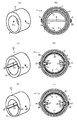
図2(C)は、中空部22内に一対の凹溝23を対称に形成した円筒形を呈する本発明の連結具(筒形体)20を示し、各凹溝23を貫通して一対の透孔24が穿孔されている。
図2(D)に示すように、予めビーム4の透孔4aにブラインドナット28を固定しておき、上記連結具20をビーム2,4間に介在させる。この際、上記ナット28の頭部は、連結具20の各凹溝23内に収容される。係る状態で、ビーム2における左右の透孔2a及び連結具20の透孔24にボルト25を座金26を介して挿入し、且つ上記ナット28の雌ねじ部27にねじ結合する。これにより、一対の短いボルト25により、連結具20を介してビーム2,4を同軸心にして連結した本発明のインパネリィンフォースメント1aを容易に形成することができる。
図2(E)は、中空部22が軸心に対し偏心した円筒形を呈する本発明の連結具(筒形体)20′を示し、前記と同様の凹溝23及び透孔24を有する。
図2(F)に示すように、前記同様にして連結具20′をビーム2,4間に介在し、ボルト25とブラインドナット28とをねじ結合することにて、互いの軸心が偏心したビーム2,4を連結する本発明のインパネリィンフォースメント1a′を容易に形成することができる。
【0018】
図3は、更に異なる参考形態の連結具と、これを用いた参考形態のインパネリィンフォースメントに関する。図3(A)に示す参考形態の連結具30は、水平片31と垂直片32とを直交させた断面十字形のアルミニウム合金の押出形材からなり、図示で左側の端面からその軸心方向に沿って右端の手前までの位置に、水平片31と垂直片32の各中間において断面がカーブした一対ずつのスリット(内嵌合部)33,34を形成している。上記の各スリット33,34は、図3(A)において左端側から見た際に一つの円形軌跡と一致する。また、水平片31及び垂直片32のカーブする外曲面(外嵌合部)からスリット33,34まで貫通するねじ通し穴35a,36aが形成され、更に、スリット33,34からねじ通し穴35a,36aと同一の軸心上で水平片31又は垂直片32の中心部に向かって進入するねじ穴35b,36bが穿設されている。
【0019】
図3(B)に示すように、連結具30の水平片31及び垂直片32のカーブする4つの外曲面を太径のビーム2の端部における中空部3に接触させつつ挿入すると共に、反対側から各スリット33,34内に細径のビーム4の端部を挿入する。この状態で、上下左右のビーム2,4の透孔2a等及び上記ねじ通し穴35a,36aを貫通してねじ穴35b,36b内にボルト37を座金38を介してねじ込むことにより、連結具30を介してビーム2,4を同軸心にして連結したインパネリィンフォースメントを精度良く容易に形成することができる。
【0020】
図3(C)は、各スリット33,34を軸心に対し図示で下方に偏心して形成した参考形態の連結具30′を示す。図3(D)に示すように、前記同様にして連結具30′をビーム2,4の端部間に介在し、ボルト37をねじ結合することにより、互いの軸心が偏心したビーム2,4を連結したインパネリィンフォースメントを容易に形成することができる。尚、連結具30,30′は、スリット33,34を含めてアルミニウム合金等の精密鋳造又は鍛造により成形することも可能である。
尚、上記スリット33,34は、ビーム4の端部に一致するカーブ形の断面形状とすることが望ましい。但し、ビーム4の端部が挿入可能であれば、スリット33,34をカーブしない直線形の断面形状としても良い。また、ねじ穴35a,36aが互いに干渉しないように、位置をずらして水平片31又は垂直片32を貫通する貫通孔とし、これらに図示しない通しボルトを座金を介して挿通し且つナットを締結することによっても、容易にインパネリィンフォースメントを形成することができる。
【0021】
図3(E)に示す参考形態の連結具40は、断面が互いに略相似形で且つ同軸心にして一体化された大径部(内嵌合部)41と小径部(内嵌合部)46とからなり、それぞれ垂直片42,47及び水平片43,48を直交させた断面十字形のアルミニウム合金からなる鋳造品或いは鍛造品である。また、垂直片42,47と水平片43,48のカーブした外曲面における中央付近には、ねじ穴44,49が各々穿設されている。更に、上記大径部41と小径部46との間には、上下左右に対称に4つの垂直な段部45が位置する。
図3(F)に示すように、連結具40の大径部41における垂直片42及び水平片44のカーブする4つの外曲面を太径のビーム2の端部における中空部3内に接触させつつ、大径部41を嵌合する。また、小径部46における垂直片47及び水平片48のカーブする4つの外曲面に、反対側から細径のビーム4における端部の中空部5を接触させつつ、係る小径部46自体を中空部5内に嵌合すると共に、ビーム4の端面を各段部45に当接する。
【0022】
上記のように、連結具40とビーム2,4とを嵌合した状態で、ビーム2,4の透孔2a,4a及び上記ねじ穴44,49内にボルト37を座金38を介してねじ込む。これにより、連結具40を介してビーム2,4を同軸心にして連結した参考形態のインパネリィンフォースメントを精度良く容易に形成できる。
尚、連結具40における大径部41と小径部46とを、それぞれの軸心を偏心させて一体化した図示しない連結具を用いることにより、図3(D)と同様な互いの軸心が偏心しているビーム2,4を連結した参考形態のインパネリィンフォースメントを容易に形成できる。
【0023】
前記垂直片42及び水平片44を貫通し且つ互いに干渉しない一対の貫通孔を穿孔し、これらに図示しない通しボルトを座金を介して挿通し、ナットを締結することにより、容易にインパネリィンフォースメントを形成することもできる。
また、ビーム2,4を互いに相似形でない断面のものとすることもできる。或いは、ビーム2,4の寸法関係や相互の軸心の偏心形態により、ビーム2,4の断面が互いに重複し合い、且つ太径のビーム2に細径のビーム4を挿入できない寸法関係とすることも可能となる。
更に、連結具40には、例えばポリカーボネート等の高強度を有する樹脂の成形体を適用することも可能である。
【0024】
図4は、前記と別異の参考形態を有する連結具とビーム、及びこれらを用いた参考形態のインパネリィンフォースメントに関する。
図4(A),(B)に表・裏面を示す参考形態の連結具50は、円盤形の基部51と、図示で基部51の左側面上において互いに同じ円形軌跡の一部から対称に立設する薄肉で4つの円弧片52と、基部51の右側面上において外周縁57の内側に同様に立設する厚肉で4つの円弧片56とを一体に有する。係る円弧片52,56の中心は、基部51の軸心と同じ位置にある。
また、円弧片52同士や円弧片56同士の間には、基部51の両側面の同じ位置に隙間53,58が形成され、これらに挟まれた基部51には透孔55が穿孔されている。4つの円弧片52の内側には、基部51を貫通する4つの透孔54が等間隔に穿孔されている。尚、各円弧片52,56は、各々全体として1つの外/内嵌合部を形成する。また、連結具50には、アルミニウム合金又は前記樹脂からなる鋳造品或いは鍛造品が用いられる。
【0025】
図4(C)は、押出形材からなる太径のビーム2bの端面を示し、その中空部3内の4カ所に等間隔でビスホール2cが長手方向に沿って突設されている。尚、細径のビーム4bにも同様にビスホール4cを形成しておく。
図4(D)に示すように、連結具50における各円弧片52の内周面内にビーム4bの端部を挿入し、図示で基部51の右側面から透孔54を通じて、セルフタッピングボルト59をビスホール4c内にねじ込む。次に、連結具50における各円弧片56の外周面上にビーム2bの端部を挿入し、図示で基部51の左側面から透孔55を通じて、セルフタッピングボルト59をビスホール2c内にねじ込む。これにより、連結具50を介してビーム2b,4bを同軸心にして連結した参考形態のインパネリィンフォースメントを容易且つ精度良くに形成できる。
【0026】
尚、各円弧片52,56の中心を、基部51の表裏面における異なる位置にそれぞれ配置し、各円弧片52,56を互いに偏心する位置に設けることにより、互いの軸心が偏心したビーム2b,4bを連結した参考形態のインパネリィンフォースメントを容易に形成できる。また、連結具50は、円形断面以外の断面形状を有するビーム間にも、必要な変更を加えることにて適用可能である。但し、何れにても上記ボルト59の配設位置は、ビスホール2c等の位置に合わせる。
【0027】
図4(E),(F)に示す参考形態の連結具60は、円盤形の基部61と、図4(E)で基部61の左側面上において、該基部61と同心に立設するスリーブ(外嵌合部)62と、その内周部63の底面における基部61に対称に穿孔した一対の透孔64とを含む。また、図4(F)で基部61の右側面上には、外周縁65の内側に、同じ円形軌跡の一部であって、互いに対称で且つ厚肉な一対の円弧片(内嵌合部)66が立設し、円弧片66,66の両端間に円柱形の隙間68が形成される。係る隙間68には、上記透孔64の一端が開口している。
更に、各隙間68の中央付近を横切り且つ一つの円形軌跡を形成すると共に、各円弧片66の内側に位置するリング溝67が設けられると共に、各隙間68とリング溝67に囲まれた太い略円柱形の中央部69が突設されている。且つ、各円弧片66の外周面の中央には、ここからリング溝67を横切って中央部69内に達するねじ穴69aが穿設されている。
【0028】
図4(G)に示すように、連結具60におけるスリーブ62の内周部63に、細径のビーム4bの端部を挿入し、且つ各ビスホール4cを各透孔64に位置合わせした後、反対側からセルフタッピングボルト59を透孔64を通じてビスホール4c内にねじ込む。次に、各円弧片66の外周面上に中空部3を接触させつつ太径の前記ビーム2を嵌合し、その端面を外周縁65に当てた後、ビーム2の透孔2aから上記ボルト59をねじ穴69a内にねじ込む。これにより、図4(G)に示すように、連結具60を介してビーム2,4bを同軸心にして連結した参考形態のインパネリィンフォースメントを容易且つ精度良くに形成できる。
【0029】
また、図4(G)は、図中の破線で示すように、ビーム2をその中空部3内に同心の内円環部2dを併設した二重管とし、且つビーム4bをその外側に同心の外円環部4dを併設した二重管とし、両ビーム2,4bを連結具60を介して連結する形態をも示す。尚、ビーム2,4bにおいて、内・外円環部2d,4dを支持する図示しないウェブは、連結具60寄りの端部を予め切り欠いておく。
連結具60におけるスリーブ62の内・外周部に、ビーム4bとその外円環部4dの各端部を嵌合し、連結具60の透孔64の右側からビーム4bのビスホール4c内に向けて上記ボルト59をねじ込む。次に、連結具60の外周縁65にビーム2の端部を当接し且つリング溝67内にビーム2の内円環部2dの端部を嵌合し、上記ボルト59をビーム2の透孔2aとねじ穴69aを通して、中央部69内にねじ込むこともできる。この場合、スリーブ62は内・外嵌合部になると共に、リング溝67は内嵌合部になり、且つ円弧片66は外嵌合部となる。
以上のような連結具60によれば、直径の異なるビーム2,4bを互いに同心にして容易に連結することができる。
【0030】
図4(H),(I)に左右側面を示す参考形態の連結具70は、円盤形の基部71と、図4(H)で基部71の左側面上において、この基部71と偏心して立設するスリーブ(外嵌合部)72と、その内周部73の底面における基部71に対称に穿孔した一対の透孔74とを含む。また、図4(I)で基部71の右側面上には、外周縁75の内側に基部71と同心のスリーブ(内嵌合部)76が立設し、これに一対の透孔78が穿孔されている。即ち、スリーブ72,76は互いに偏心して形成されている。尚、スリーブ76の内周部77の底面には上記透孔74が開口している。
【0031】
図4(J)に示すように、連結具70におけるスリーブ72の内周部73に、細径のビーム4bの端部を挿入し、且つ各ビスホール4cを各透孔74に位置合わせした後、反対側からセルフタッピングボルト59を透孔74を通じてビスホール4c内にねじ込む。次に、スリーブ76の外周面上に中空部3を接触させつつ太径の前記ビーム2の端面を外周縁75に当接した後、ブラインドリベット79をビーム2の透孔2aから透孔78内に打設する。これにより、図4(J)に示すように、連結具70を介してビーム2,4bを互いに偏心させて連結した参考形態のインパネリィンフォースメントを容易且つ精度良くに形成できる。また、ブラインドリベット79に替えて、座金を介した通しボルトを貫通した後、ナットを締結しても、インパネリィンフォースメントを形成することができる。
【0032】
図5(A)は、前記と異なる参考形態のインパネリィンフォースメント80を示す。
インパネリィンフォースメント80は、図5(A)で右側の押出形材からなる太径のビーム82と左側の細径のビーム84とを備える。ビーム82,84は、略半円形の中空部83,85と共に、一部に平坦面82a,84aを長手方向の全長に沿って有する。係るビーム82,84の間には連結具(筒形体)86が介在し、これも平坦部86aを有する。即ちビーム82,84、及び連結具86は、互いに相似形の断面略半円形状を有する。図8(A)に示すように、連結具86は、ビーム82の左端部における中空部83内に挿入されると共に、且つその中空部内にビーム84の右端部を挿入する。この状態で、前記図1(F)と同様にビーム82,84、連結具86、及び中空部85を貫通するボルトにナットを締結する。これにより、ビーム82,84は、連結具86を介して同軸心で連結される。
【0033】
更に、ビーム82,84の両外端部には、ボデー接続用ブラケット87,88が対称に固定される。両者は、ビーム82,84の外端部を挿入して嵌合する略円筒形で平坦部を有する包囲部87a,88aと、その一端に一体に設けた矩形のフランジ89,89とを一体にしたアルミニウム合金からなる鋳造品である。
包囲部87a,88aには前記図1(F)に示したと同様に、ボルトがビーム82,84の外端部と共に貫通し、これにナットを締結する。これにより、上記ブラケット87,88は、ビーム82,84の外端部に個別に固定される。尚、各フランジ89には、以上のようなインパネリィンフォースメント80を図示しない自動車に接続するためのボルト貫通用の透孔89aが複数穿孔されている。
【0034】
以上のような参考形態のインパネリィンフォースメント80では、ビーム82,84、及び連結具86が平坦面82a等を相似形にして有する非円形で且つ異形の断面を有するため、これらを互いに精度良く容易に嵌合でき、且つ安定した状態でボルトの挿通やナットの締結を行うことができる。
図5(B)は、インパネリィンフォースメント80の使用状態を示し、太径のビーム82の平坦面82aを活用して、ステアリングホイール90のステアリングシャフト91に取付けたステアリングコラムブラケット92を、上記平坦面82aに接触させた安定した姿勢で、図示しないボルト等により強固に固定することができる。尚、上記平坦面82aや細径のビーム84における平坦面84aを活用して、図示しないエアバッグ取付用やエアコン取付用ブラケット、或いはカウルツウブレースやフロアブレース等を固定して取り付けることも可能である。
【0035】
図5(C)〜(H)は、非円形の断面を有する本発明に適用可能なビームに関する。尚、ここでは相似形断面を有する太径(大径)及び細径(小径)のビームの双方を共通して示す。
図5(C)に示すビーム93は、中空の押出形材からなり正五角形の断面を有し、図5(D)に示すビーム94は、正六角形の断面を有する。また、図5(E)に示すビーム95は、正八角形の断面を有し、図5(F)に示すビーム96は、正十二角形の断面を有する。更に、図5(G)に示すビーム97は、中空の押出形材からなり各コーナーにアールを付した略長方形の断面を有し、上下一対の長辺には平坦面97aを有する。加えて、図5(H)に示すビーム98は、長円形の断面を有する中空形材であり、図中の上下に一対の平坦面98aを有する。
これらのビーム93〜98も、前記インパネリィンフォースメント80と同様に、太径及び細径のビームを相似形断面の連結具を介して容易に連結できると共に、外周面の平坦部97a等を活用することにより、各種のブラケットを容易に固定することも可能となる。また、ビーム93〜96の断面を、それぞれの変形多角形とすることも、押出形材を用いることにより容易である。
【0036】
図6は、円形の断面を有する参考形態のビームに関する。尚、ここでも相似形断面を有する太径及び細径のビームの双方を共通して示す。
図6(A)に示すビーム100は、アルミニウム合金の押出形材からなり、中空部101を含む円形の断面を有し、その外周面103上に軸心方向に沿って、4つの突条102を対称で且つ長手方向の全長に沿って突設している。係るビーム100は、各突条102により剛性を高められる。また、ビーム100を太径及び細径のビームの双方用いる場合、両者の間に介在する連結具には細径のビーム100の各突条102を受け入れる凹溝を予めその中空部の内周面に形成する。
係る突条102と凹溝との嵌合により、ビーム100の回転を防止できる。
【0037】
また、図6(B)に示すビーム104も、アルミニウム合金の押出形材からなり、中空部105を含む円形の断面を有し、その内周面105上に軸心方向に沿って、4つの突条106を対称で且つ長手方向の全長に沿って突設している。係るビーム104は、各突条106により剛性を高められる。また、ビーム104を太径及び細径のビームの双方用いる場合、両者の間に介在する連結具には、少なくとも太径のビーム104の各突条106を受け入れる凹溝を、予めその中空部の内周面に形成しておくことが望ましい。係る突条106と凹溝との嵌合により、ビーム104の回転を防ぐことができる。
【0038】
更に、図6(C)に示すビーム108も押出形材からなり、中空部110を含む円形の断面を有し、その外周面に軸心方向に沿って、4つの幅広いカーブ形の突条114とこれらの間の凹溝112を、互いに対称で且つ長手方向の全長に沿って突設している。係るビーム108は、各突条114により剛性を高められる。
また、ビーム108を太径及び細径のビームの双方用いる場合、両者の間に介在する連結具には細径のビーム108の各突条114を受け入れる凹溝を、予めその中空部の内周面に形成しておくことが望ましい。係る突条114と凹溝との嵌合により、ビーム108の回転を防ぐことができる。
【0039】
加えて、図6(D)に示すビーム116も押出形材からなり、内部に互いに対称な4つの断面扇形の中空部118と、これらを仕切る断面十字形の仕切壁119とを、その長手方向の全長に沿って設けている。係るビーム116は、上記仕切壁119を内設することで剛性を高めている。また、ビーム116を太径及び細径のビームの双方に用いる場合、両者の間に介在する連結具には各ビーム116の各中空部118内に嵌合する複数の突起(嵌合部)を、予め両側にそれぞれに形成しておくことが望ましい。尚、以上の突条102,106,114及び仕切壁119は、前記非円形断面のビーム93〜98にも適宜適用することができる。
【0040】
図7は、前記形態以外の本発明に適用可能なボデー接続用ブラケットに関する。尚、これらは相似形断面の太径及び細径のビームの双方に共通して用い得るものとして説明する。
図7(A)に示すボデー接続用ブラケット120は、断面正八角形の前記ビーム95の外端部を挿入して嵌合する断面正八角形の包囲部122と、その一端に一体に設けた矩形のフランジ121とを有する。また、図7(A)に示すように、上記包囲部122には左右一対の透孔123が穿孔され、フランジ121には上下一対の透孔124が穿孔されている。上記透孔123には前記ビーム95を貫通して固定するボルトが、上記透孔124には車体に固定するボルトが貫通する。
【0041】
また、図7(B)に示すボデー接続用ブラケット125は、4つの突条102を外周面103に有する前記ビーム100の外端部を挿入して嵌合する断面円形の包囲部127と、その一端に一体に設けた矩形のフランジ121とを有する。
図7(B)に示すように、上記包囲部127の内周面には上記突条102を受け入れる凹溝128が4つ対称に形成され、且つ左右の凹溝128には上記ビーム100を貫通し且つ固定するボルト用の透孔129が穿孔されている。また、フランジ126には、車体に固定するボルトが貫通する上下一対の透孔126aが穿孔されている。
【0042】
更に、図7(C)に示すボデー接続用ブラケット130は、4つの突条106を内周面105に有する前記ビーム104の外端部に挿入して嵌合する略円柱形の挿入部132と、その一端に一体に設けた矩形のフランジ131とを有する。
図7(C)に示すように、上記挿入部132の外周面には上記突条106を受け入れる凹溝133が4つ対称に形成され、且つ左右の凹溝133間には前記ビーム104を貫通し且つ固定するボルト用の透孔134が穿孔されている。また、フランジ131には、車体に固定するボルトが貫通する上下一対の透孔131aが穿孔されている。
【0043】
図7(D)に示すボデー接続用ブラケット135は、断面円形で中空部3に一対のビスホール2c,4cを有する前記ビーム2b,4bの外端部に挿入して嵌合する略円柱形の挿入部137と、その一端に一体に設けた矩形のフランジ136とを有する。また、図7(D)に示すように、上記挿入部137には上下一対の円弧溝138が形成され、前記ビーム2b,4bのビスホール2c,4cを受け入れる。更に、挿入部137にはビーム2b,4bを固定するボルト用の水平な透孔139が貫通し、フランジ136には車体に固定するボルト用の上下一対の透孔136aが穿孔されている。
【0044】
また、図7(E)に示すボデー接続用ブラケット140は、前記ビーム100の外端部を挿入して嵌合する断面円形の包囲部144と、その一端に一体に設けた矩形のフランジ141とを有する。
図7(E)に示すように、上記包囲部144の内周面には前記突条102を受け入れる凹溝146が3つ形成され、且つ包囲部144の上部に開口する狭い間隙145の両側には一対の平板部147が立設する。各平板部147に穿孔した透孔148内に、図示せぬボルトを貫通しナットを締結して、一対の平板部147同士を弾性により接近させる。これにより、包囲部144内に挿入されたビーム100の外端部をねじ止めすることなく、強固に固定することができる。また、フランジ141には、車体に固定するボルトが貫通する上下一対の透孔142が穿孔されている。尚、間隙145の奥部はフランジ141において終端となる。
【0045】
更に、図7(F)に示すボデー接続用ブラケット150は、前記ビーム100の外端部を挿入して嵌合する断面略円形の包囲部152を有する包囲体151と、その両端に固定する矩形のプレート156とからなる。包囲体151における包囲部152の内周面には、開口部153を除いて前記ビーム100の突条102を受け入れる3つの凹溝154が形成され、且つ開口部153の両縁には一対の平板片155が対称に延びている。各平板片155をプレート156に接触させて、ボルト158等にて固定することにより、本ブラケット150が得られる。
尚、プレート156の上下端には、車体に固定するボルト用の一対の透孔157が穿孔されている。このブラケット150によれば、包囲部152に前記ビーム100の外端部を挿入し、係る包囲体151とプレート156とをボルト止めすることにより、インパネリィンフォースメントを強固に車体に固定することができる。尚、包囲体151には、アルミニウム合金の押出形材を短尺に切断するのみで活用できる。尚、上記ブラケット150は、車体側の取付面がインパネリィンフォースメントの長手方向と同じ向きである場合に好適である。
【0046】
図8(A)は、前記太径のビーム2に固定する本発明に適用可能なステアリングシャフト取付用ブラケット160を示す。このブラケット160は、上記ビーム2を挿通する中空部163を有する上部の円環部162と、下部の台形部161とを一体に有するアルミニウム合金等からなる鋳造品である。上記円環部162は、中空部163の長手方向に沿ったスリット164を挟んで一対のフランジ165を有する。各フランジ165の透孔166に図示しないボルトを通し且つナットを締結することにより、スリット164を狭める。これにより、中空部163内に予め挿通したビーム2に、本ブラケット160が強固に固定される。
【0047】
また、図8(A)に示すように、台形部161には、中空部163と平面視で直交する通し孔169が一対の傾斜面167,168間を貫通している。この通し孔169にステアリングシャフトが挿通される。以上のようなブラケット160をビーム2に固定することにより、前記インパネリィンフォースメント1にステアリングシャフトを確実に支持することができる。尚、中空部163の断面形状を変更することにより、前記ビーム82,93〜98,100〜116を有するインパネリィンフォースメントに本ブラケット160を固定することもできる。
【0048】
図8(B)は、前記太径のビーム2に固定する異なる形態のステアリングシャフト取付用ブラケット170を示す。このブラケット170は、上半体171と下半体177とからなるアルミニウム合金等の鋳造品である。上半体171は、中央の中空部172と、その長手方向に沿ったスリット173を挟んで一対のフランジ174とを有する。各フランジ174の透孔175に図示しないボルトを通し且つナットを締結することにで、スリット173を狭める。これにより、中空部172内に予め挿通したビーム2に強固に本ブラケット170が固定される。
上半体171の両端のフランジ176には、透孔176aが穿孔されている。
【0049】
また、図8(B)に示すように、下半体177は、断面略逆Ω字形を有し、上記中空部172と直交する円弧溝178と、その開口部178aの両側の一対のフランジ179とからなる。図示のように、上半体171の各フランジ176に上記フランジ179を接触させ、透孔176aフランジ179の図示しない透孔とにボルトを通し且つナットを締結する。これにより、予め円弧溝178内に挿通したステアリングシャフトを、前記インパネリィンフォースメント1に確実に支持することができる。尚、中空部172の断面形状を変更することにより、前記ビーム82,93〜98等に本ブラケット170を固定することもできる。
【0050】
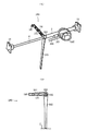
図9(A),(B)は、外端部にボデー接続用ブラケット11,15を有する一対のビーム2,4を連結する参考形態の連結具180を示す。
この連結具180は、内嵌合部182と図示しない外嵌合部を両側に有する円筒形の基部181と、基部181からフロアF上に垂下するフロアブレース183と、基部181から水平に伸び且つ図示しないカウルと連結するカウルツウブレース184とを一体に有するアルミニウム合金等の鋳造品からなる。上記ブレース184は、複数の開口185と、その先端にて直角に伸び且つボルト孔を有する固定フランジ186とを有する。係る連結具180によれば、ビーム2,4を連結して容易にインパネリィンフォースメントを形成できると共に、得られたインパネリィンフォースメント自体をフロアF及びカウルに確実に支持させることができる。尚、連結具180において、フロアブレース183又はカウルツウブレース184の一方を省略しても良い。また、前記筒形体の連結具における露出する端面、あるいは、内嵌合部または外嵌合部を両側に有する連結具における基片の外周面に、適宜形状のフロアブレース等を一体に突設したり、エアコン等の取付ブラケットを形成することも可能である。
【0051】
本発明は、以上において説明した各形態に限定されるものではない。
例えば、一つのインパネリィンフォースメントに、断面形状が相違する一対のビームを用いることもできる。この場合、各ビームの端部間に介在する連結具は各ビームの断面形状に倣った断面形状の内・外周面を併有する筒形体を適用する。
また、一対のビームをそれぞれの軸心が互いに僅かに傾斜して交差するように連結具を介して両者を連結することも可能である。この場合、連結具における筒形体の内外周面や内嵌合部または外嵌合部の軸心を、同様に傾斜して交差するように形成しておくものとする。
更に、ビームの外周面に突設する突条を、ボルト等の機械的手段による前記各種ブラケット類の固定に活用することも可能である。
また、ボデー接続用ブラケットのフランジは、前記形態のような矩形に限らず、取付面の形状や周辺の部材との納まり具合に応じ且つその機能を損なわないような形状にすることも可能である。
【0052】
【発明の効果】
請求項1のインパネリィンフォースメントによれば、全体を軽量化できるため、搭載する自動車の燃料効率を高められる。また、断面形状が大小異なる一対のビームの端部同士の間において、両者を個別に所定の位置に容易に位置決めでき、且つボルト・ブラインドナットの締結作業のみの簡単な工程からなる少ない工数で迅速に組立られる。更に、リサイクルにも適するため、環境上の観点からも好ましいインパネリィンフォースメントとすることが可能となる。
また、請求項3のインパネリィンフォースメントによれば、ビームを任意の中空断面を形成できるため一層軽量化を図れ、且つ組立後における不用意な回転を防止し得る。しかも、一対のビームに取付けるブラケット類との機械的手段による固定も納まり良く容易に行うことができ、組立作業を一層簡易化することが可能となる。
【0053】
更に、請求項7のインパネリィンフォースメントによれば、ステアリングシャフト取付用ブラケットを、断面が大きなビームに容易に固定することができ、例えば上記ブラケットを予め固定したインパネリィンフォースメントを形成できるため、車体内部の組立工数を低減することも可能となる。
【図面の簡単な説明】
【図1】(A)は本発明の前提的な参考形態のインパネリィンフォースメントの一形態を示す正面図、(B)は(A)中のB−B線に沿った断面図、(C)は(A)中の一点鎖線部分Cの拡大断面図、(D)はこれに用いた連結具の斜視図、(E)は(A)中のE−E線に沿った断面図。
【図2】(A),(B)は異なる参考形態の連結具の斜視図とこれを用いた参考形態のインパネリィンフォースメントの断面図、(C),(E)は本発明の連結具を示す斜視図、(D),(F)はこれらを用いて一対のビームを連結した本発明のインパネリィンフォースメントの断面図。
【図3】(A),(C),(E)は更に異なる参考形態の連結具を示す斜視図、(B),(D),(F)はこれらを用いて一対のビームを連結した参考形態のインパネリィンフォースメントの断面図。
【図4】(A),(B)は別の参考形態の連結具の各側面を示す斜視図、(C)は異なる参考形態のビームを示す端面図、(D)は上記の連結具に一対のビームを連結した状態を示す断面図、(E),(F)及び(H),(I)は更に別形態の連結具の各側面を示す斜視図、(G),(J)はこれらに一対のビームを連結した状態を示す断面図。
【図5】(A)は異なる参考形態のインパネリィンフォースメントを示す斜視図、(B)はその使用状態を示す概略図、(C)〜(H)は本発明に適用可能な異なる形態のビームを示す断面図。
【図6】(A)〜(D)は別なる参考形態のビームを示す断面図。
【図7】 (A)〜(F)は本発明に適用可能な異なる形態のボデー接続ブラケットを示す斜視図。
【図8】(A),(B)は本発明のインパネリィンフォースメントに用いるステアリングシャフト取付用ブラケットを示す斜視図。
【図9】(A)は異なる参考形態の連結具を用いた参考形態のインパネリィンフォースメントの斜視図、(B)はその使用状態を示す概略図。
【図10】(A)は従来のインパネリィンフォースメントを示す斜視図、(B)はその使用状態を示す概略図
【符号の説明】
1a,1a′…………………………インパネリィンフォースメント
2,4,93〜98…………………ビーム
3,5…………………………………中空部
11,15,120,125,130,135,140,150…ボデー接続用ブラケット
20,20′…………………………連結具
23……………………………………凹溝
25……………………………………ボルト
27……………………………………雌ねじ部
28……………………………………ブラインドナット
160,170………………………ステアリングシャフト取付用ブラケット[0001]
BACKGROUND OF THE INVENTION
The present invention is arranged along the width direction of a vehicle body inside a dashboard of an automobile, and for fixing a mounting bracket for supporting a steering shaft, various instruments, an air conditioner, an airbag, or the like. About instrument panel reinforcement.
[0002]
[Prior art]
In general, as shown in FIG. 10A, the
An
[0003]
Further, as shown in FIG. 10A, a
In addition, the
However, the
Note that the outer diameters of the
[0004]
[Problems to be Solved by the Invention]
An object of the present invention is to solve the problems in the conventional techniques described above, to reduce the overall weight, to reduce the number of assembly steps, and to provide an instrument panel reinforcement suitable for recycling.
[0005]
[Means for Solving the Problems]
In order to solve the above-described problems, the present invention utilizes a hollow extruded profile of an aluminum alloy for a pair of beams constituting an instrument panel reinforcement, and is bolted.eyesIt was made with a focus on application.
That is, the instrument panel reinforcement according to the present invention (Claim 1) is mounted on an automobile and is made of an aluminum alloy hollow extruded shape, and has a pair of left and right beams having different cross-sectional shapes, and an intervening space between the pair of beams. And with both beamsboltStopMedeAnd a coupler that couples the pair of beams by fixing.Only,The coupler is a cylindrical body located between beam ends where the pair of beams overlap and fit, a concave groove opening in the hollow portion, and a through hole penetrating the concave groove, Is formed,The end of the beam with a small cross-sectional shape is fitted into the hollow portion of the coupler so that the head of the blind nut fixed in advance in the through hole of the beam with a small cross-sectional shape is accommodated in the groove.,The coupling tool is fitted into the hollow portion at the end of the beam having a large cross-sectional shape, and the coupling tool is interposed between the pair of beams.,A bolt inserted into the through hole of the beam having a large cross-sectional shape and the through hole of the connector is screwed to the female thread portion of the blind nut.It is characterized by that.
[0006]
According to this, a pair of beams is made of aluminum alloy.Hollow pushSince it is made of a molded material, the overall weight can be reduced, and the fuel efficiency of the mounted vehicle can be improved. Moreover,Between the ends of a pair of beams having different cross-sectional shapes,boltAnd blindNatsuWithLess man-hours consisting of a simple process with only fasteningRapidlyAssembled. Furthermore, since it is a material suitable for recycling and has high fuel efficiency, it is possible to obtain an instrument panel reinforcement that is preferable from an environmental point of view.
The size of the cross-sectional shape indicates a form in which the outer diameter of the pair of beams is a large diameter and a thin diameter, and a form in which the cross-sectional shape is large or small.
Furthermore, an aluminum alloy is preferable for the connector because of ease of recycling, but a cast or forged product made of other metals and alloys can also be used, and a resin molded product having high strength can be applied. . Further, a cowl toe brace connected to the cowl, a floor brace connected to the floor, and the like can be integrated with the connecting tool.
[0007]
The pair of beams are substantially similar in cross section.AndThe axis of each otherCoaxial orIt is fixed to the connector in an eccentric state,Instrumental force(Claim 2)Is also included.
According to this, according to the type of the vehicle to be mounted and the position of the brackets to be mounted, the instrument panel reinforcement of the required shape and form can be easily achieved simply by fixing the pair of beams to the above-mentioned coupler. Can be formed, and design restrictions in the vicinity of the dashboard can be reduced.
Further, the pair of beams includes an instrument panel reinforcement including a hollow portion along an axial center and having an irregular cross section such as a circular shape, a regular polygon shape, or a deformed polygon shape.(Claim 3)Is also included.
According to this, since an arbitrary cross-sectional shape can be obtained, the weight can be further reduced, and inadvertent rotation of the beam after assembly can be prevented, and mechanical means with brackets attached to a pair of beams Can be easily fixed, and the assembly work can be further simplified.
[0008]
Also,A pair of concave grooves that open into the hollow portion of the connector and through holes that pass through the concave grooves are formed symmetrically, and the cross-sectional shape of the pair of blind nuts fixed to the pair of through holes is large. An instrument panel reinforcement (Claim 4) is also included, which is formed by screwing the bolts inserted into a pair of through holes provided symmetrically with the beam..
[0009]
Further, a body connection bracket fixed by mechanical means such as screwing while being fitted to the outer end portions is fixed to both outer end portions of the pair of beams fixed and connected via the connecting tool. Instrument panel reinforcement(Claim 5)Is also included.
Accordingly, the body connecting bracket having a shape corresponding to the cross-sectional shape of each beam can be easily fixed at each outer end portion of the pair of beams having large and small cross sections.
[0010]
still,UpBracketIsIn addition to a cast or forged product made of aluminum alloy or the like, it is also possible to apply a resin molded product having high strength.
The body connection bracket includes an instrument panel reinforcement including an enclosure portion or an insertion portion fitted to each outer end portion of the pair of beams, and a flange integrally provided at one end thereof.(Claim 6)Is also included.
According to this, since the outer end portion of each beam can be easily prevented from moving in the axial direction, the pair of beams can be safely and reliably connected to the body.
[0011]
Furthermore,An instrument panel reinforcement (Claim 7) is also included in which a steering shaft mounting bracket having a holding portion that surrounds the beam and is orthogonal to the beam is fixed to a beam having a large cross section among the beams..
[0012]
ThisAccording to this, the bracket for mounting the steering shaft can be easily fixed to a beam having a large cross section, and for example, an instrument panel reinforcement in which the bracket is fixed in advance can be formed. Is also possible.
[0013]
DETAILED DESCRIPTION OF THE INVENTION
In the following, preferred embodiments of the present invention will be described with reference to the drawings.
FIG. 1 (A) shows the present invention.Assumed reference formThe front view of the
As shown in FIG. 1C, the
[0014]
As shown in FIGS. 1A and 1F,
The
[0015]
Like the aboveReference formAccording to the
[0016]
Figure 2 is differentreferenceFormAnd embodiments of the inventionThis connector and thisEtIt relates to instrument panel reinforcement using In the following description, common symbols are used for the same elements and the like as those in the above embodiment.
FIG. 2A shows a cylindrical shape in which the hollow portion 7 is eccentric with respect to the axis.Reference formA connector (tubular body) 6 'is shown. As shown in FIG. 2 (B), the connecting tool 6 'is interposed between the large-diameter and thin-diameter beams 2 and 4, and a
[0017]
FIG. 2C shows a cylindrical shape in which a pair of
As shown in FIG. 2D, a
FIG. 2 (E) shows a cylindrical shape in which the
As shown in FIG. 2 (F), the connecting shaft 20 'is interposed between the beams 2 and 4 in the same manner as described above, and the
[0018]
3 is further differentreferenceForm connector and using thisReference formAbout instrument panel reinforcement. As shown in FIG.
[0019]
As shown in FIG. 3B, the four outer curved surfaces of the
[0020]
In FIG. 3C, the
The
[0021]
As shown in FIG.
As shown in FIG. 3F, the four outer curved surfaces of the
[0022]
As described above, the
In addition, by using a coupling tool (not shown) in which the large-
[0023]
A pair of through-holes that penetrate the
Further, the beams 2 and 4 may have cross sections that are not similar to each other. Alternatively, due to the dimensional relationship of the beams 2 and 4 and the eccentric forms of the mutual axial centers, the cross sections of the beams 2 and 4 overlap each other, and the dimensional relationship is such that the thin beam 4 cannot be inserted into the large beam 2. It is also possible.
Further, a resin molded body having high strength such as polycarbonate can be applied to the
[0024]
FIG. 4 is different from the above.referenceCONNECTOR AND BEAM HAVING FORM, AND USING THEMReference formAbout instrument panel reinforcement.
FIG. 4 (A),(B) shows the front and back
Further, between the
[0025]
FIG. 4C shows an end face of a large-
As shown in FIG. 4D, the end of the
[0026]
In addition, the center of each
[0027]
Fig. 4 (E),Shown in (F)
Further, a circular groove is formed across the center of each
[0028]
As shown in FIG. 4 (G), after inserting the end portion of the
[0029]
4 (G), as indicated by a broken line in the figure, the beam 2 is a double tube in which a concentric
The end portions of the
According to the connecting
[0030]
Fig. 4 (H),(I) shows the left and right
[0031]
As shown in FIG. 4 (J), after inserting the end portion of the
[0032]
FIG. 5A is different from the above.referenceAn
The
[0033]
Further,
In the same manner as shown in FIG. 1 (F), bolts pass through the surrounding
[0034]
Like the aboveReference formIn the
FIG. 5 (B) shows the use state of the
[0035]
5 (C)-(H) have non-circular cross sections.Applicable to the present inventionRegarding the beam. Here, both large diameter (large diameter) and small diameter (small diameter) beams having similar cross sections are shown in common.
A
Similar to the
[0036]
FIG. 6 has a circular cross sectionReference formRegarding the beam. Here, both the large-diameter beam and the small-diameter beam having similar cross sections are shown in common.
A
The rotation of the
[0037]
A
[0038]
Further, the
In addition, when both the large-diameter beam and the small-diameter beam are used as the
[0039]
In addition, the
[0040]
FIG. 7 shows other forms.Applicable to the present inventionIt relates to a bracket for body connection. These will be described assuming that they can be used in common for both large-diameter and narrow-diameter beams having similar cross sections.
The
[0041]
Further, a
As shown in FIG. 7B, four
[0042]
Furthermore, the
As shown in FIG. 7C, four
[0043]
The
[0044]
Further, a
As shown in FIG. 7E, three
[0045]
Further, a
A pair of through
[0046]
FIG. 8 (A) is fixed to the large-diameter beam 2.Applicable to the present inventionA steering
[0047]
Further, as shown in FIG. 8A, the
[0048]
FIG. 8B shows a different form of the steering
Through
[0049]
Further, as shown in FIG. 8B, the
[0050]
9A and 9B, a pair of beams 2 and 4 having
The
[0051]
The present invention is not limited to the embodiments described above.
For example, a pair of beams having different cross-sectional shapes can be used for one instrument panel reinforcement. In this case, the coupler interposed between the end portions of each beam is a cylindrical shape having both inner and outer peripheral surfaces having a cross-sectional shape following the cross-sectional shape of each beam.BodyApply.
It is also possible to connect the pair of beams via a connecting tool so that the axes of the beams intersect with each other while being slightly inclined. In this case, the inner and outer peripheral surfaces of the cylindrical body and the innerMating part orSimilarly, the axis of the outer fitting portion is formed so as to intersect with each other in an inclined manner.
Furthermore, it is also possible to utilize the protrusion protruding from the outer peripheral surface of the beam for fixing the various brackets by mechanical means such as bolts.
Further, the flange of the body connecting bracket is not limited to the rectangular shape as described above, but can be shaped according to the shape of the mounting surface and the degree of fit with the surrounding members and without impairing its function. .
[0052]
【The invention's effect】
In the instrument panel reinforcement of claim 1According to this, because the overall weight can be reduced, the fuel efficiency of the mounted vehicle can be increased.The In addition, between the ends of a pair of beams having different cross-sectional shapes, they can be easily positioned individually at predetermined positions, and can be quickly performed with a small number of man-hours consisting of only a bolt / blind nut fastening operation. Assembled. Furthermore,Since it is also suitable for recycling, it is possible to obtain an instrument panel reinforcement that is preferable from an environmental point of view.
ClaimsThreeAccording to the instrument panel reinforcement, the beam can be formed in an arbitrary hollow cross section, so that the weight can be further reduced and inadvertent rotation after assembly can be prevented. In addition, the fixing with the brackets attached to the pair of beams can be easily performed with good fit, and the assembling work can be further simplified.
[0053]
More, ContractClaim7According to the instrument panel reinforcement, the steering shaft mounting bracket can be easily fixed to a beam having a large cross section. For example, an instrument panel reinforcement in which the bracket is fixed in advance can be formed. Can also be reduced.
[Brief description of the drawings]
FIG. 1 (A) shows the present invention.Assumed reference form(B) is a sectional view taken along line BB in (A), (C) is an enlarged sectional view of an alternate long and short dash line portion C in (A), (D) is a perspective view of the connector used for this, (E) is sectional drawing along the EE line in (A).
[Fig. 2] (A), (B)DifferentreferenceForm connectorSectional view of the instrument panel reinforcement of the reference form using this, (C), (E) are perspective views showing the coupler of the present invention, and (D), (F) are used to connect a pair of beams.Of the present inventionA sectional view of an instrument panel reinforcement.
FIG. 3 (A), (C), (E) are further differentreferenceThe perspective view which shows the coupling tool of a form, (B), (D), (F) connected a pair of beam using theseReference formA sectional view of an instrument panel reinforcement.
[Figure 4] (A) and (B) are differentreferenceThe perspective view which shows each side of the connection tool of a form, (C) is differentreferenceThe end view which shows the beam of form, (D) is sectional drawing which shows the state which connected a pair of beam to said coupling tool, (E), (F) and (H), (I) are connection of another form The perspective view which shows each side of a tool, (G), (J) is sectional drawing which shows the state which connected a pair of beam to these.
FIG. 5 (A) is differentreferenceThe perspective view which shows the instrument panel reinforcement of form, (B) is the schematic which shows the use condition, (C)-(H)Applicable to the present inventionSectional drawing which shows the beam of a different form.
[Figure 6] (A) to (D) are differentReferenceSectional drawing which shows the beam of form.
[Figure 7] (A) ~ (F)Applicable to the present inventionThe perspective view which shows the body connection bracket of a different form.
FIGS. 8A and 8B are perspective views showing a steering shaft mounting bracket used in the instrument panel reinforcement of the present invention.
FIG. 9 (A) is differentreferenceUsing form couplerReference formThe perspective view of an instrument panel reinforcement, (B) is the schematic which shows the use condition.
FIG. 10A is a perspective view showing a conventional instrument panel reinforcement, and FIG. 10B is a schematic view showing a use state thereof.
[Explanation of symbols]
1a, 1a '………………………… Instrumental reinforcement
2, 4, 93-98…………………beam
3, 5………………………………… Hollow
11,15,120,125,130,135,140,150 ... Body connection bracket
20, 20 '………………………… Connector
23……………………………………Ditch
25……………………………………bolt
27……………………………………Female thread
28……………………………………Blind nut
160, 170 ………………………… Steering shaft mounting bracket
Claims (7)
上記一対のビーム間に介在し且つ両ビームとボルト止めで固定することにより、上記一対のビームを連結する連結具と、を含み、
上記連結具は、上記一対のビーム同士が重複して嵌合するビーム端部同士の間に位置する筒形体であり、その中空部内に開口する凹溝と、当該凹溝を貫通する透孔とが形成されており、
断面形状が小さいビームの透孔に予め固定したブラインドナットの頭部を、上記凹溝内に収容するように、当該断面形状が小さいビームの端部を上記連結具の中空部に嵌合し、
断面形状が大きいビームの端部の中空部内に上記連結具を嵌合して、当該連結具を上記一対のビーム間に介在させると共に、
上記断面形状が大きいビームの透孔および上記連結具の透孔に挿入したボルトを上記ブラインドナットの雌ねじ部にねじ結合してなる、
ことを特徴とするインパネリィンフォースメント。A pair of left and right beams mounted on an automobile, made of an aluminum alloy hollow extruded shape, and having different cross-sectional shapes,
By fixing the above interposed between a pair of beams and the beams and bolts and stopper, seen including and a connector for connecting the pair of beams,
The connector is a cylindrical body located between beam ends where the pair of beams overlap and fit, and a concave groove opening in the hollow portion, and a through hole penetrating the concave groove, Is formed ,
Fitting the end of the beam with a small cross-sectional shape to the hollow portion of the connector so that the head of the blind nut fixed in advance in the through hole of the beam with a small cross-sectional shape is accommodated in the concave groove ,
The coupling tool is fitted in the hollow portion at the end of the beam having a large cross-sectional shape, and the coupling tool is interposed between the pair of beams ,
A bolt inserted into the through hole of the beam having a large cross-sectional shape and the through hole of the connector is screwed to the female thread portion of the blind nut .
Instrument panel reinforcement characterized by that.
ことを特徴とする請求項1に記載のインパネリィンフォースメント。The pair of beams are substantially similar to each other in cross section , and are fixed to the connector in a state in which the axes of the beams are coaxial or eccentric.
The instrument panel reinforcement according to claim 1.
ことを特徴とする請求項1または2に記載のインパネリィンフォースメント。The pair of beams includes a hollow portion along the axial center and has an irregular cross section such as a circular shape, a regular polygon shape, or a deformed polygon shape.
The instrument panel reinforcement according to claim 1 or 2.
ことを特徴とする請求項1乃至3の何れかに記載のインパネリィンフォースメント。 A pair of concave grooves that open into the hollow portion of the connector and through holes that pass through the concave grooves are formed symmetrically, and the cross-sectional shape of the pair of blind nuts fixed to the pair of through holes is large. It is formed by screwing the bolts inserted into a pair of through holes provided symmetrically to the beam ,
The instrument panel reinforcement according to any one of claims 1 to 3.
ことを特徴とする請求項1乃至4の何れかに記載のインパネリィンフォースメント。A body connecting bracket fixed by mechanical means such as screwing while being fitted to the outer end portions is fixed to both outer end portions of the pair of beams fixed and connected via the connecting tool. ,
The instrument panel reinforcement according to any one of claims 1 to 4 .
ことを特徴とする請求項5に記載のインパネリィンフォースメント。The body connection bracket includes a surrounding portion or an insertion portion fitted to each outer end portion of the pair of beams, and a flange integrally provided at one end thereof.
The instrument panel reinforcement according to claim 5 .
ことを特徴とする請求項1乃至6の何れかに記載のインパネリィンフォースメント。A steering shaft mounting bracket that has a holding portion that surrounds the beam and is orthogonal to the beam is fixed to the beam having a large cross section among the beams.
The instrument panel reinforcement according to any one of claims 1 to 6 .
Priority Applications (1)
| Application Number | Priority Date | Filing Date | Title |
|---|---|---|---|
| JP2000067843A JP4496592B2 (en) | 2000-03-10 | 2000-03-10 | Instrumental force |
Applications Claiming Priority (1)
| Application Number | Priority Date | Filing Date | Title |
|---|---|---|---|
| JP2000067843A JP4496592B2 (en) | 2000-03-10 | 2000-03-10 | Instrumental force |
Publications (3)
| Publication Number | Publication Date |
|---|---|
| JP2001253368A JP2001253368A (en) | 2001-09-18 |
| JP2001253368A5 JP2001253368A5 (en) | 2008-01-31 |
| JP4496592B2 true JP4496592B2 (en) | 2010-07-07 |
Family
ID=18586973
Family Applications (1)
| Application Number | Title | Priority Date | Filing Date |
|---|---|---|---|
| JP2000067843A Expired - Fee Related JP4496592B2 (en) | 2000-03-10 | 2000-03-10 | Instrumental force |
Country Status (1)
| Country | Link |
|---|---|
| JP (1) | JP4496592B2 (en) |
Cited By (1)
| Publication number | Priority date | Publication date | Assignee | Title |
|---|---|---|---|---|
| WO2024023178A1 (en) | 2022-07-27 | 2024-02-01 | Faurecia Interieur Industrie | Dashboard crossmember assembly for a vehicle, comprising two longitudinal portions fastened together by means of a fastening coupling |
Families Citing this family (25)
| Publication number | Priority date | Publication date | Assignee | Title |
|---|---|---|---|---|
| JP4157773B2 (en) * | 2003-01-30 | 2008-10-01 | カルソニックカンセイ株式会社 | Cross car beam mounting structure for vehicles |
| WO2005095187A1 (en) * | 2004-04-01 | 2005-10-13 | Calsonic Kansei Corporation | Steering support member structure |
| CN100542871C (en) | 2004-05-21 | 2009-09-23 | 昭和电工株式会社 | Steering support beam |
| JP2006264444A (en) * | 2005-03-23 | 2006-10-05 | Showa Denko Kk | Steering support beam and manufacturing method |
| JP2006306248A (en) * | 2005-04-28 | 2006-11-09 | Showa Denko Kk | Steering support beam and manufacturing method thereof |
| JP4628197B2 (en) * | 2005-06-28 | 2011-02-09 | 株式会社神戸製鋼所 | Instrument panel reinforcement structure and instrument panel mounting bracket |
| JP4668707B2 (en) * | 2005-07-06 | 2011-04-13 | 三菱アルミニウム株式会社 | Deck cross member, Deck cross member manufacturing method |
| DE102005043504A1 (en) * | 2005-09-12 | 2007-04-26 | Behr Gmbh & Co. Kg | Cross member for a motor vehicle |
| JP5244565B2 (en) * | 2008-12-01 | 2013-07-24 | カルソニックカンセイ株式会社 | Body strength member structure |
| WO2011036780A1 (en) | 2009-09-25 | 2011-03-31 | トヨタ自動車株式会社 | Arrangement for mounting instrument reinforcement for a vehicl |
| DE102010031201B4 (en) * | 2010-07-09 | 2012-01-26 | Thiel & Hoche Gmbh & Co. Kg | Tubular body, in particular for use in the automotive sector |
| DE102011101581A1 (en) * | 2011-05-13 | 2012-11-15 | Volkswagen Aktiengesellschaft | Carrier i.e. cross beam, for instrument panel of vehicle, has carrier elements made of aluminum such that socket is connected with actuated connection region, where region is actuated with elements and bonded to firmly bonded region |
| DE102011052250A1 (en) * | 2011-07-28 | 2013-01-31 | Dr. Ing. H.C. F. Porsche Aktiengesellschaft | Cockpit carrying structure of a motor vehicle |
| FR2995862B1 (en) * | 2012-09-24 | 2014-09-19 | Peugeot Citroen Automobiles Sa | AUTOMOTIVE VEHICLE DASHBOARD TRAVERSE CONSISTING OF TWO TUBES AND A FORCE LEG IN COMPOSITE MATERIAL |
| PT106739A (en) * | 2013-01-16 | 2014-07-16 | Sodecia Ct Tecnológico S A | STEERING COLUMN SUPPORT FOR CROSS BEAMS WITH LOCAL REINFORCEMENT AND FIXING ELEMENT |
| JP6091915B2 (en) * | 2013-02-05 | 2017-03-08 | ユニプレス株式会社 | Steering member |
| JP6214947B2 (en) * | 2013-07-12 | 2017-10-18 | フタバ産業株式会社 | Instrument panel reinforcement |
| FR3043050B1 (en) | 2015-10-29 | 2017-11-24 | Faurecia Interieur Ind | VEHICLE TRAVERSE |
| JP6755810B2 (en) * | 2017-01-31 | 2020-09-16 | 株式会社Uacj | Instrument panel beam, pair of brackets and instrument panel beam junction |
| JP6953846B2 (en) * | 2017-07-12 | 2021-10-27 | トヨタ自動車株式会社 | Steering support structure |
| CN108673758B (en) * | 2018-05-21 | 2020-03-17 | 重庆晶宇光电科技有限公司 | Optical glass recovery process |
| FR3089199B1 (en) * | 2018-11-30 | 2022-05-13 | Plastic Omnium Advanced Innovation & Res | Internal reinforcement for motor vehicle tank |
| JP7180458B2 (en) * | 2019-03-07 | 2022-11-30 | マツダ株式会社 | Structural member and manufacturing method thereof |
| CN112298374A (en) * | 2020-10-16 | 2021-02-02 | 重庆金康赛力斯新能源汽车设计院有限公司 | Instrument tube beam assembly |
| EP4194323A1 (en) * | 2021-12-10 | 2023-06-14 | Dura Automotive Systems GmbH | Modular transverse carrier |
Citations (1)
| Publication number | Priority date | Publication date | Assignee | Title |
|---|---|---|---|---|
| JPH0483879U (en) * | 1990-11-30 | 1992-07-21 |
Family Cites Families (1)
| Publication number | Priority date | Publication date | Assignee | Title |
|---|---|---|---|---|
| JPH05238421A (en) * | 1992-02-28 | 1993-09-17 | Yamakawa Ind Co Ltd | Steering member in vehicle |
-
2000
- 2000-03-10 JP JP2000067843A patent/JP4496592B2/en not_active Expired - Fee Related
Patent Citations (1)
| Publication number | Priority date | Publication date | Assignee | Title |
|---|---|---|---|---|
| JPH0483879U (en) * | 1990-11-30 | 1992-07-21 |
Cited By (2)
| Publication number | Priority date | Publication date | Assignee | Title |
|---|---|---|---|---|
| WO2024023178A1 (en) | 2022-07-27 | 2024-02-01 | Faurecia Interieur Industrie | Dashboard crossmember assembly for a vehicle, comprising two longitudinal portions fastened together by means of a fastening coupling |
| FR3138404A1 (en) | 2022-07-27 | 2024-02-02 | Faurecia Interieur Industrie | Dashboard crossmember assembly for a vehicle comprising two longitudinal portions fixed together by means of a fixing connector |
Also Published As
| Publication number | Publication date |
|---|---|
| JP2001253368A (en) | 2001-09-18 |
Similar Documents
| Publication | Publication Date | Title |
|---|---|---|
| JP4496592B2 (en) | Instrumental force | |
| EP1337429B1 (en) | A joint structure and method for making a joint structure | |
| US7150489B2 (en) | Reinforcing structure for automotive vehicles | |
| EP3536530B1 (en) | Vehicle body structure | |
| US20050110302A1 (en) | Integrated steel cross-car beam | |
| WO2007004616A1 (en) | Deck cross member and method of producing deck cross member | |
| US20010038231A1 (en) | Impact absorbing structure of vehicle | |
| JP4487366B2 (en) | Instrumental force | |
| US9950745B2 (en) | Cockpit cross beam with variable steering column angle of inclination | |
| JPH10338161A (en) | Joint part structure of vehicle frame | |
| JPH08183478A (en) | Reinforcement support structure | |
| JP2019031216A (en) | Impact absorbing member and impact absorbing device | |
| JP2006143156A (en) | Instrument panel reinforcement | |
| JP2018043548A (en) | Instrument panel reinforcement and manufacturing method of instrument panel reinforcement | |
| JP2000126832A (en) | Production of vehicle body frame | |
| JPH10324269A (en) | Front chassis frame | |
| JPH0113010Y2 (en) | ||
| JP2019026044A (en) | Reinforcement structure of passenger compartment front part | |
| EP3786032B1 (en) | Instrument panel holder for a motor vehicle | |
| JPH0189275U (en) | ||
| JPH0542685Y2 (en) | ||
| JP3586051B2 (en) | Deck cross member | |
| US20210253154A1 (en) | Steering support | |
| JPH10175564A (en) | Mounting structure of steering member | |
| JPH05330454A (en) | Supporting structure of instrument panel reinforcement |
Legal Events
| Date | Code | Title | Description |
|---|---|---|---|
| A621 | Written request for application examination |
Free format text: JAPANESE INTERMEDIATE CODE: A621 Effective date: 20060628 |
|
| A521 | Written amendment |
Free format text: JAPANESE INTERMEDIATE CODE: A523 Effective date: 20071207 |
|
| A977 | Report on retrieval |
Free format text: JAPANESE INTERMEDIATE CODE: A971007 Effective date: 20090227 |
|
| A131 | Notification of reasons for refusal |
Free format text: JAPANESE INTERMEDIATE CODE: A131 Effective date: 20090303 |
|
| A521 | Written amendment |
Free format text: JAPANESE INTERMEDIATE CODE: A523 Effective date: 20090323 |
|
| A131 | Notification of reasons for refusal |
Free format text: JAPANESE INTERMEDIATE CODE: A131 Effective date: 20090901 |
|
| A521 | Written amendment |
Free format text: JAPANESE INTERMEDIATE CODE: A523 Effective date: 20091029 |
|
| TRDD | Decision of grant or rejection written | ||
| A01 | Written decision to grant a patent or to grant a registration (utility model) |
Free format text: JAPANESE INTERMEDIATE CODE: A01 Effective date: 20100323 |
|
| A01 | Written decision to grant a patent or to grant a registration (utility model) |
Free format text: JAPANESE INTERMEDIATE CODE: A01 |
|
| A61 | First payment of annual fees (during grant procedure) |
Free format text: JAPANESE INTERMEDIATE CODE: A61 Effective date: 20100405 |
|
| FPAY | Renewal fee payment (event date is renewal date of database) |
Free format text: PAYMENT UNTIL: 20130423 Year of fee payment: 3 |
|
| R150 | Certificate of patent or registration of utility model |
Ref document number: 4496592 Country of ref document: JP Free format text: JAPANESE INTERMEDIATE CODE: R150 Free format text: JAPANESE INTERMEDIATE CODE: R150 |
|
| FPAY | Renewal fee payment (event date is renewal date of database) |
Free format text: PAYMENT UNTIL: 20130423 Year of fee payment: 3 |
|
| FPAY | Renewal fee payment (event date is renewal date of database) |
Free format text: PAYMENT UNTIL: 20140423 Year of fee payment: 4 |
|
| LAPS | Cancellation because of no payment of annual fees |