JP4494397B2 - Induction heating device - Google Patents
Induction heating device Download PDFInfo
- Publication number
- JP4494397B2 JP4494397B2 JP2006349001A JP2006349001A JP4494397B2 JP 4494397 B2 JP4494397 B2 JP 4494397B2 JP 2006349001 A JP2006349001 A JP 2006349001A JP 2006349001 A JP2006349001 A JP 2006349001A JP 4494397 B2 JP4494397 B2 JP 4494397B2
- Authority
- JP
- Japan
- Prior art keywords
- operating frequency
- inverter circuit
- load
- circuit
- induction heating
- Prior art date
- Legal status (The legal status is an assumption and is not a legal conclusion. Google has not performed a legal analysis and makes no representation as to the accuracy of the status listed.)
- Expired - Fee Related
Links
Images


Landscapes
- General Induction Heating (AREA)
- Induction Heating Cooking Devices (AREA)
Description
本発明は、少なくとも1つのフルブリッジ構成のインバータ回路によって駆動される誘導加熱コイルと、少なくとも1つのハーフブリッジ構成のインバータ回路によって駆動される誘導加熱コイルを備えた誘導加熱装置に関するものであり、インバータ回路及びその制御部の制御によって、上記誘導加熱コイルを同時に又は選択して使用することが可能な誘導加熱装置に関する。 The present invention relates to an induction heating coil including an induction heating coil driven by at least one inverter circuit having a full-bridge configuration and an induction heating coil driven by at least one inverter circuit having a half-bridge configuration. The present invention relates to an induction heating apparatus capable of using the induction heating coil simultaneously or selectively by controlling a circuit and its control unit.
誘導加熱装置は、交流電源を整流回路で直流電源に変換し、この直流電源をインバータ回路に供給して高周波交流電流に変換し、この高周波交流電流を加熱コイルに流すことで加熱コイルに交番磁界を発生させるものである。この交番磁界により、トッププレートを介して加熱コイルに近接配置された鍋などの磁性材料で構成された金属製調理具(負荷と呼ぶこともある)の底に渦電流を発生させ、発生した渦電流と金属製調理具の抵抗により発生する熱を利用して調理が行なわれる。 The induction heating device converts an alternating current power source into a direct current power source using a rectifier circuit, supplies the direct current power source to an inverter circuit to convert it into a high frequency alternating current, and flows the high frequency alternating current through the heating coil to thereby generate an alternating magnetic field in the heating coil. Is generated. This alternating magnetic field generates eddy currents at the bottom of a metal cooking utensil (sometimes called a load) made of a magnetic material such as a pan placed close to the heating coil via the top plate. Cooking is performed using the heat generated by the current and the resistance of the metal cookware.
ところで、誘導加熱調理装置の第1の従来技術として、ハーフブリッジ構成のスイッチング素子を用いた2口以上の誘導加熱装置で、2個のスイッチング素子を交互に導通させる駆動部を備え、この駆動部は、上記2個のスイッチング素子の制御を、導通比一定で周波数を変化させながら導通させる方法と、一定の周波数で導通比を変化させながら導通させる方法とに切り替え、あるいは同時に使用し、1口のみで使用するときには、2口以上を同時に使用するときよりもパワーを大きくすることができる技術が開示されている(例えば、特許文献1参照)。 By the way, as a first prior art of an induction heating cooking apparatus, a two-or-more induction heating apparatus using a switching element having a half-bridge configuration is provided with a driving unit that alternately conducts two switching elements. Switches the control of the above two switching elements between a method of conducting while changing the frequency at a constant conduction ratio and a method of conducting while changing the conduction ratio at a constant frequency, or using them simultaneously. A technique is disclosed that can increase the power when used alone, as compared with the case where two or more ports are used simultaneously (see, for example, Patent Document 1).
第2の従来技術として、フルブリッジ構成のスイッチング素子を用いた加熱装置で、加熱出力に応じて遅延量のみを変えた制御信号を個別の電流経路のスイッチング素子に供給しオン/オフ駆動させることにより、インバータ回路の周波数の相違に起因する干渉音の発生を防止する技術が開示されている(例えば、特許文献2参照)。 As a second conventional technique, in a heating device using a switching element having a full bridge configuration, a control signal in which only a delay amount is changed according to a heating output is supplied to a switching element of an individual current path to be turned on / off. Discloses a technique for preventing the generation of interference sound due to the difference in frequency of the inverter circuit (see, for example, Patent Document 2).
特許文献1で示される従来の誘導加熱装置では、その負荷回路である複数の加熱コイルを駆動するインバータ回路を加熱口毎に備え、インバータ回路をそれぞれディスクリート部品で加熱口毎に個別に構成しており、その結果、回路規模の増大やコストの増大を招くだけでなく、ノイズ耐性の向上を図ることが困難であるという問題があった。
In the conventional induction heating device shown in
この発明は、このような問題を解決するためになされたものであり、回路構成の簡素化とコスト低減を図り、さらにノイズ耐性の大きい誘導加熱装置を得ることを目的とする。 The present invention has been made to solve such a problem, and aims to simplify the circuit configuration and reduce the cost, and to obtain an induction heating apparatus having a high noise resistance.
本発明に係る誘導加熱装置は、少なくとも2つの各加熱コイルと対応する共振コンデンサから成る負荷回路を駆動するインバータ回路を、スイッチング素子を2個直列接続したアームを3組内蔵する1つのIPM(Intelligent Power Module)で構成され、そのIPMに内蔵された3アームの内の2アームは、フルブリッジ構成のインバータ回路に用いられ、IPMに内蔵された3アームの内の残りの1アームは、ハーフブリッジ構成のインバータ回路に用いられたものである。
The induction heating apparatus according to the present invention includes an inverter circuit that drives a load circuit composed of a resonance capacitor corresponding to at least two heating coils, and one IPM (Intelligent) that includes three arms each having two switching elements connected in series. 2 of the 3 arms built in the IPM are used for a full-bridge inverter circuit, and the remaining 1 of the 3 arms built in the IPM is a half bridge. It is used for the inverter circuit of a structure .
この発明によれば、少なくとも2つの加熱コイルを駆動するインバータ回路を、スイッチング素子を2個直列接続したアームを3組内蔵する1つのIPMで構成するので、回路構成の簡素化とコスト低減が図れ、さらにノイズ耐性が向上するという効果がある。 According to the present invention, since the inverter circuit for driving at least two heating coils is configured by one IPM having three sets of arms each having two switching elements connected in series, the circuit configuration can be simplified and the cost can be reduced. In addition, there is an effect that noise resistance is further improved.
実施の形態1.
図1は、本発明の実施の形態1における誘導加熱装置の構成を示す回路図である。同図において、誘導加熱装置10は、商用交流電源1とダイオードブリッジで構成される全波整流器2と平滑コンデンサ3とチョークコイル4とハーフブリッジ構成のインバータで構成される加熱回路5(以下、ハーフブリッジ回路という)と、フルブリッジ構成のインバータで構成される加熱回路(以下、フルブリッジ回路という)6と、これらを制御する制御回路7で構成される。
また、ハーフブリッジ回路5は、加熱コイル51と、共振コンデンサ52と、2つのスイッチング素子53、54と、これらのスイッチング素子がOFFした時のスパイク電圧の発生を防止するスナバコンデンサ55とから構成される。
また、フルブリッジ回路6は、加熱コイル61と、共振コンデンサ62と、4つのスイッチング素子63〜66と2つのスナバコンデンサ67、68とから構成される。
FIG. 1 is a circuit diagram showing the configuration of the induction heating apparatus according to
The half-
The
次に、実施の形態1の動作について図1を用いて説明する。
商用交流電源1から出力された交流電圧は、全波整流回路2によって全波整流されて直流電圧に変換される。また、平滑用コンデンサ3とチョークコイル4で構成されるフィルタによって、回路後段のインバータ回路(後述)で発生する高周波成分を低減するものである。ダイオードブリッジ2で全波整流された直流電圧は、ハーフブリッジ構成のインバータ回路(以下、ハーフブリッジ回路と呼ぶ)5とフルブリッジ構成のインバータ回路(以下、フルブリッジ回路と呼ぶ)6に供給される。
Next, the operation of the first embodiment will be described with reference to FIG.
The AC voltage output from the commercial
一方、制御部7は、ハーフブリッジ回路5のスイッチング素子53、54を高周波駆動するための原信号をIPM9(後述)に与え、スイッチング素子53、54が交互に高周波駆動されるとともに、共振コンデンサ52の充放電を利用し、加熱コイル51に高周波電流が流れる。この場合、ハーフブリッジ構成のインバータ回路であるため加熱コイル51には電源電圧の半分しか印加されず、出力可能な火力は小さい。また制御部7はフルブリッジ回路6のスイッチング素子63、64、65、66を高周波駆動するための原信号をIPM9(後述)に与え、スイッチング素子63と66の組、64と65の組が交互に高周波駆動されることで、加熱コイル61に高周波電流が流れる。この場合、フルブリッジ構成のインバータ回路であるため加熱コイル61には電源電圧がそのまま印加されるため、出力可能な火力は加熱コイル51よりも大きい。
従って、使用者は、調理の形態に応じて、出力可能な火力の大きい側(以下、火力大側と呼ぶ)加熱コイル61と出力可能な火力の小さい側(以下、火力小側と呼ぶ)の加熱コイル51を使い分けることができるので、調理効率が向上する。
また、制御部7には誘導加熱装置の負荷である鍋の材質を判定する負荷材質判定手段70と鍋の材質と前記インバータ回路の動作条件とを対応させたテーブルを有し、この負荷材質判定手段70が判定した鍋の材質と、負荷材質判定手段70が判定した鍋の材質に応じて上記テーブルから鍋の材質に対応する動作周波数等を取得して、インバータ回路を駆動するように制御する。さらに、鍋に投入する加熱出力の制御は、後述の操作部において使用者が加熱出力の設定を行い、設定された加熱出力となるように、上述の取得した動作周波数や、導通比を変化させるように制御部7によって制御される。
On the other hand, the
Therefore, the user can change the side of the heating power that can be output (hereinafter referred to as the heating power large side) with the
Further, the
ところで、2個のスイッチング素子を直列に接続したアームを3組(スイッチング素子の合計数は6個)と、それらのスイッチング素子を駆動するための駆動回路を内蔵したIPM(Intelligent Power Module)が3相モータ制御用インバータの構成部品として市販されている。そこで、上記ハーフブリッジ回路5のスイッチング素子53と54から構成されるアーム、及びフルブリッジ回路6のスイッチング素子63と64から構成されるアームと65と66から構成されるアームとして上記IPM内蔵の3組のアームを流用することができる。
このIPMを流用することで、本発明の誘導加熱装置は以下のIPM特有の優れた特徴を発揮することができる。
(1) スイッチング素子とそれらを駆動する回路はIPMに内蔵されるため、回路のパターン配線が極めて短い。従って、パターン配線のインダクタンス成分が極めて小さく、ノイズが重畳しにくいため、ノイズ耐性が非常に良い。
(2) 火力大側の加熱コイルで使用されるフルブリッジ回路と、火力小側の加熱コイルで使用されるハーフブリッジ回路の双方を1つのIPMで構成できる。従って、それぞれのインバータに個別に駆動回路などを設ける必要がなく、回路構成を簡素化できる。
(3) 従来は、上記インバータ回路のスイッチング素子をディスクリート部品で構成していたのに対して、1つのIPMを利用するだけで済むため、小型化、省電力を図ることができる。
(4) インバータ回路の構成に際して、従来は部品点数が多く、作業工数が多かったのに対して、本発明では安価な市販品であるIPMを1個利用するだけで済み、その結果作業工数も少ないため大幅なコスト低減を図ることができる。
(5) 回路部品がチップ内に収容されているため、信頼性が高い。
By the way, three sets of arms in which two switching elements are connected in series (the total number of switching elements is six) and three IPMs (Intelligent Power Modules) incorporating a drive circuit for driving these switching elements are provided. It is commercially available as a component of a phase motor control inverter. Therefore, the IPM built-in 3 as the arm composed of the
By diverting this IPM, the induction heating device of the present invention can exhibit the following excellent features specific to IPM.
(1) Since the switching elements and circuits for driving them are built in the IPM, the circuit pattern wiring is extremely short. Therefore, since the inductance component of the pattern wiring is extremely small and noise is not easily superimposed, noise resistance is very good.
(2) Both the full bridge circuit used in the heating coil on the large thermal power side and the half bridge circuit used in the heating coil on the small thermal power side can be configured by one IPM. Therefore, it is not necessary to provide a drive circuit or the like for each inverter, and the circuit configuration can be simplified.
(3) Conventionally, the switching element of the inverter circuit is composed of discrete components. However, since only one IPM is used, miniaturization and power saving can be achieved.
(4) In the configuration of the inverter circuit, in the past, the number of parts was large and the work man-hours were large. However, in the present invention, it is only necessary to use one IPM which is an inexpensive commercial product. Since there are few, it can aim at a significant cost reduction.
(5) Since the circuit components are housed in the chip, the reliability is high.
実施の形態2.
この実施の形態2では、IPMで構成されたハーフブリッジ回路とフルブリッジ回路を制御部によってそれぞれ独立に制御する形態について説明する。
図2は、本発明の実施の形態2における誘導加熱装置の構成を示す回路図である。同図において、図1と同符号は同一または相当部分を示すので説明を省略する。制御部7は、ハーフブリッジ回路動作周波数設定部71と、フルブリッジ回路動作周波数設定部72とを備えており、操作部8には、火力小側の火力設定を行うスイッチ81と火力大側の火力設定を行うスイッチ82が設けられており、火力小側のスイッチ81は、ハーフブリッジ回路動作周波数設定部71と接続されている。また、火力大側のスイッチ82は、フルブリッジ回路動作周波数設定部72と接続されている。
また、ハーフブリッジ回路動作周波数設定部71はIPM9内に備わり、スイッチング素子53、54を駆動する駆動回路に接続されている。
また、フルブリッジ回路動作周波数設定部72はIPM9内に備わり、スイッチング素子63〜66を駆動する駆動回路に接続されている。
In the second embodiment, a mode in which a half bridge circuit and a full bridge circuit configured by IPM are independently controlled by a control unit will be described.
FIG. 2 is a circuit diagram showing a configuration of the induction heating apparatus according to
The half-bridge circuit operating
The full bridge circuit operating
次に、実施の形態2の動作について図2を用いて説明する。実施の形態1と同じ部分については説明を省略し、異なる部分について説明する。
使用者は、調理の際に、調理対象の種類や量に応じて、操作部8の火力小側のスイッチ81と火力大側のスイッチ82の両方またはいずれか一方を使い分ける。
使用者が火力小側のスイッチ81を操作し、加熱コイルの51の火力を調整しようとする場合には、火力小側のスイッチ81から火力に応じた制御信号を発生し、この信号はハーフブリッジ回路動作周波数設定部71に送られる。ハーフブリッジ回路動作周波数設定部71は、火力小側のスイッチ81から火力に応じた制御信号が入力されると、その制御信号に応じた駆動用原信号を生成し、IPM9内の駆動回路に入力し、ハーフブリッジ回路5を駆動する。
また、使用者が火力大側のスイッチ82を操作した場合には、火力大側のスイッチ82から火力に応じた制御信号を発生し、この信号はフルブリッジ回路動作周波数設定部72に送られる。フルブリッジ回路動作周波数設定部72は、火力大側のスイッチ82から火力に応じた制御信号が入力されると、その制御信号に応じた駆動用原信号を生成し、IPM9内の駆動回路に入力し、フルブリッジ回路6を駆動する。
ここで、ハーフブリッジ回路動作周波数設定部71とフルブリッジ回路動作周波数設定部72の動作周波数の決定方法について説明する。火力に応じた制御信号がハーフブリッジ回路動作周波数設定部71もしくはフルブリッジ回路動作周波数設定部72に入力されると、火力投入前に制御部7の負荷材質判定手段70によって先ず、負荷である鍋の材質を判定する動作を実行する。また、鍋の材質を判定する目的としては、鍋と加熱コイル及び共振コンデンサから成る負荷の回路の共振点が、鍋の材質や鍋の大きさ等によって変化するため、その共振点よりも遅れの位相の範囲で適切な動作周波数を選定する必要があるためである。判定の仕方には種々方法があるが、例えば、ある動作周波数でインバータ回路を駆動し、そのときの加熱コイルに流れる電流或いは、インバータ回路に流れる電流などと、制御部7に有している負荷の材質と前記インバータ回路の動作条件(ある周波数で動作させたときの加熱コイル電流やインバータ回路電流など)とを対応させたテーブルから鍋の材質を判定し、インバータ回路の動作周波数を決定する。
インバータ回路の動作周波数を決定した後、火力に応じた例えば導通比を決定し、ハーフブリッジ回路動作周波数設定部71やフルブリッジ回路動作周波数設定部72で、それぞれの駆動用原信号を生成する。
火力小側のスイッチ81と火力大側のスイッチ82の双方を操作した場合には、同様にして、ハーフブリッジ回路5はハーフブリッジ回路動作周波数設定部71が設定した周波数で駆動され、同時にフルブリッジ回路6はフルブリッジ回路動作周波数設定部72が設定した周波数で駆動される。これにより、ハーフブリッジ回路5とフルブリッジ回路6はそれぞれ独立した周波数で動作する。
Next, the operation of the second embodiment will be described with reference to FIG. A description of the same parts as those in the first embodiment will be omitted, and different parts will be described.
When cooking, the user uses either or both of the
When the user operates the
When the user operates the
Here, a method of determining the operating frequency of the half-bridge circuit operating
After determining the operating frequency of the inverter circuit, for example, a conduction ratio corresponding to the thermal power is determined, and the half-bridge circuit operating
Similarly, when both the small
このように、火力小側のハーフブリッジ回路5の動作周波数と、火力大側のフルブリッジ回路6の動作周波数をそれぞれのインバータ回路の負荷である鍋の材質に適した動作周波数で駆動することが可能である。
In this way, the operating frequency of the half-
次に、動作周波数について説明する。
人の可聴域は一般に20Hz〜20kHzとされており、この領域を外す必要がある。
また、家電機器などに用いられる赤外線リモコンの使用周波数帯域は、30kHz〜40kHz付近が多く使われており、このような周波数帯域も外して使用することが望ましい。
また、ハーフブリッジ回路5とフルブリッジ回路6を同時に動作させたときに双方の動作周波数によって発生する周波数の差が可聴域に入ると干渉音となるので、これを防ぐ必要がある。
また、鍋と加熱コイルと共振コンデンサとで構成される負荷回路のインピーダンスZは、周波数をfとすると、次の式1によって表される。
Z=(R2+(2πfL−1/2πfC)2)1/2………(1)
ここで、Rは加熱コイルと共振コンデンサから構成される負荷回路の抵抗R、Lは加熱コイルのインダクタンス、Cは共振コンデンサの容量である。
この式1から分かるように、抵抗Rは一定であるから第1項は一定であり、第2項は周波数fの増加とともに増大し、第3項は周波数fの増加とともに0に近づく。従って、20kHz以上の高周波領域では、インピーダンスZに対するインダクタンス成分Lによる寄与が相当大きくなる。従って、周波数が低いほどインピーダンスが小さく、周波数が高いほどインピーダンスが大きくなる。
また、消費電力Pは、電圧をVとすると、次の式2によって表される。
P=V2/Z………………………(2)
火力は消費電力Pに比例するので、式2より火力はインピーダンスに反比例する。従って、同じ電圧であれば周波数が低いほど火力が大きく設定可能で、周波数が高いほど得られる火力は小さくなる。
また、インバータ回路方式の違いによる火力に違いについては上述したように、ハーフブリッジ構成のインバータ回路の場合には、加熱コイル51には電源電圧の半分しか印加されないため、出力可能な火力は小さい。また、フルブリッジ構成のインバータ回路の場合には、加熱コイル61には電源電圧がそのまま印加されるため、出力可能な火力は加熱コイル51よりも大きくなる。
以上の全ての条件を考慮すると、火力大側のフルブリッジ回路6の動作周波数を20kHz〜30kHzとし、火力小側のハーフブリッジ回路5の動作周波数を40kHz以上とするのが好ましいことが分かる。
そこで、操作部8の火力大側のスイッチ82が操作された場合には、このスイッチ82からの信号を受けた制御部7のフルブリッジ回路動作周波数設定部72は、上述のように鍋の材質の判定を行った後、図3に示すようにフルブリッジ回路6の動作周波数を相対的に低い20〜30kHzに設定し、操作部8の火力が小さい側のスイッチ81が操作された場合には、このスイッチ81からの信号を受けた制御部7のハーフブリッジ回路動作周波数設定部71は、同様に鍋の材質の判定を行った後、図3に示すようにハーフブリッジ回路5の動作周波数を相対的に高い40kHz以上に設定する。
Next, the operating frequency will be described.
The human audible range is generally 20 Hz to 20 kHz, and it is necessary to remove this range.
In addition, the use frequency band of an infrared remote controller used for home appliances or the like is frequently used in the vicinity of 30 kHz to 40 kHz, and it is desirable to use it by removing such a frequency band.
Further, when the half-
Moreover, the impedance Z of the load circuit comprised with a pan, a heating coil, and a resonance capacitor is represented by the following
Z = (R 2 + (2πfL−1 / 2πfC) 2 ) 1/2 (1)
Here, R is a resistance R of a load circuit composed of a heating coil and a resonance capacitor, L is an inductance of the heating coil, and C is a capacitance of the resonance capacitor.
As can be seen from
Further, the power consumption P is expressed by the
P = V 2 / Z ........................... ( 2)
Since the thermal power is proportional to the power consumption P, the thermal power is inversely proportional to the impedance from
Further, as described above, regarding the difference in the thermal power due to the difference in the inverter circuit system, in the case of the inverter circuit having the half bridge configuration, only half of the power supply voltage is applied to the
Considering all the above conditions, it can be seen that it is preferable to set the operating frequency of the full-
Therefore, when the
これにより、火力大側と火力小側で駆動周波数を独立して設定可能であるため、それぞれのインバータ回路の負荷である鍋の材質に適した周波数で駆動することが可能である。
また、火力大側のフルブリッジ回路の動作周波数を相対的に低い20kHz〜30kHzに設定し、火力小側のハーフブリッジ回路の動作周波数を相対的に高い40kHz以上に設定するため、加熱口に応じた火力を得ることができ、快適な調理を楽しむことが可能になる。
さらに、動作周波数は、フルブリッジ回路6側を相対的に低い20kHz〜30kHzに、ハーフブリッジ回路5側を相対的に高い40kHz以上に設定するため、加熱口に応じた火力を得ることができ、快適な調理を楽しむことができる。
また、火力大側と小側の同時駆動時には、例えば、火力大側の動作周波数を22kHzに設定し、火力小側の動作周波数を45kHzに設定すれば、火力大側と火力小側の動作周波数の差は人の可聴域から外れた20kHz以上となるため、干渉音の発生を抑制することが可能になる。
As a result, the driving frequency can be set independently on the large thermal power side and the small thermal power side, and therefore, it is possible to drive at a frequency suitable for the material of the pan that is the load of each inverter circuit.
Also, the operating frequency of the full-bridge circuit on the large thermal power side is set to a relatively low 20 kHz to 30 kHz, and the operating frequency of the half-bridge circuit on the small thermal power side is set to a relatively high 40 kHz or higher. You can get a lot of firepower and enjoy a comfortable cooking.
Furthermore, since the operating frequency is set to a relatively low 20 kHz to 30 kHz on the
Further, when simultaneously driving the large thermal power side and the small thermal power side, for example, if the operating frequency on the large thermal power side is set to 22 kHz and the operating frequency on the small thermal power side is set to 45 kHz, the operating frequency on the large thermal power side and the small thermal power side Is 20 kHz or more outside the human audible range, so that it is possible to suppress the generation of interference sound.
また、制御部7は負荷材質判定手段70を備えているので、火力大側の加熱コイル61および火力小側の加熱コイル51に載置する鍋の材質に応じて適切な動作周波数を設定することができる。この場合、制御部7は、予め図4に示すような火力大側および火力小側における鍋の材質と動作周波数との対応を表すテーブルを内部の記憶部(図示せず)に記憶させておく。そして、設定部8の火力大側のスイッチ82または火力小側のスイッチ81から使用者が加熱の開始や火加減(火力の制御)を行った場合に制御信号を発生し、この信号はフルブリッジ回路動作周波数設定部72に送られる。フルブリッジ回路動作周波数設定部72は、火力大側のスイッチ82から火力に応じた制御信号が入力されると、上述のように負荷材質判定手段70によって先ず、負荷である鍋の材質を判定する動作を実行し、鍋の材質に対応した動作周波数を決定し、使用者のスイッチ82操作による制御信号に応じた駆動用原信号を生成し、IPM9内の駆動回路に入力し、フルブリッジ回路6を駆動する。設定部8の火力小側の設定スイッチ81が操作された場合においても同様に、鍋の材質に対応した動作周波数を決定し、使用者のスイッチ81操作による制御信号に応じた駆動用原信号を生成し、IPM9内の駆動回路に入力し、ハーフブリッジ回路6を駆動する。
これにより、使用する鍋の材質などに応じた適切な動作周波数で調理を行うことができ、省電力を図りつつ快適な調理を楽しむことができる。
Moreover, since the
Thereby, cooking can be performed at an appropriate operating frequency according to the material of the pan to be used, and comfortable cooking can be enjoyed while saving power.
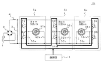
実施の形態3.
この実施の形態3では、IPM内蔵の3アームが3つのハーフブリッジ回路に用いられる形態について説明する。
図5は、本発明の実施の形態3における誘導加熱装置の構成を示す回路図である。同図において、図1と同符号は同一または相当部分を示すので説明を省略する。誘導加熱装置10は、3つの加熱コイル51a〜51cを備えた3口の誘導加熱装置である。これらの加熱コイル51a〜51cを駆動するインバータ回路は、IPM内蔵の3アームを夫々単独で使用し、火力が相対的に小さい3つのハーフブリッジ回路を構成することが可能である。
制御部7は、これらの3つのハーフブリッジ回路の周波数を独立に駆動する。
これにより、1つのIPMで3つの加熱コイルを駆動することが可能になり、装置の小型化、回路構成の簡素化、ノイズ耐性の向上が可能になる。
Embodiment 3 FIG.
In the third embodiment, a mode in which three arms with built-in IPM are used for three half-bridge circuits will be described.
FIG. 5 is a circuit diagram showing the configuration of the induction heating apparatus according to Embodiment 3 of the present invention. In the figure, the same reference numerals as those in FIG. The
The
As a result, it is possible to drive three heating coils with one IPM, and it is possible to reduce the size of the apparatus, simplify the circuit configuration, and improve noise resistance.
1 商用交流電源、2 全波整流器、3 平滑コンデンサ、4 チョークコイル、5 ハーフブリッジ回路、5a〜c ハーフブリッジ回路、6 フルブリッジ回路、7 制御部、8 操作部、9 IPM(Intelligent Power Module)、10 誘導加熱装置、51 加熱コイル、51a〜c 加熱コイル、52共振コンデンサ、52a〜c 共振コンデンサ、53 スイッチング素子、54 スイッチング素子、55 スナバコンデンサ、63 スイッチング素子、64 スイッチング素子、65 スイッチング素子、66 スイッチング素子、67 スナバコンデンサ、68スナバコンデンサ、70 負荷材質判定手段、71 ハーフブリッジ回路動作周波数設定部、72 フルブリッジ回路動作周波数設定部、81 火力大側のスイッチ、82 火力小側のスイッチ。
1 AC power supply, 2 full-wave rectifier, 3 smoothing capacitor, 4 choke coil, 5 half bridge circuit, 5 a to c half bridge circuit, 6 full bridge circuit, 7 control unit, 8 operation unit, 9 IPM (Intelligent Power Module) DESCRIPTION OF
Claims (7)
この天板の下側に配置され、前記負荷を誘導加熱する複数の加熱コイルと、
この加熱コイル毎に設けられた複数の共振コンデンサと、
前記加熱コイル毎に設けられ、交流電源を高周波電流に変換するスイッチング素子を備え、前記各加熱コイルと対応する前記共振コンデンサから成る負荷回路に前記高周波電流を流す複数のインバータ回路と、
このインバータを駆動制御する制御部と、を備え、
少なくとも2つの前記インバータ回路は、スイッチング素子を2個直列接続して成るアームを3組内蔵する1つのIPM(Intelligent Power Module)で構成され、
前記IPMに内蔵された3アームの内の2アームは、フルブリッジ構成のインバータ回路に用いられ、
前記IPMに内蔵された3アームの内の残りの1アームは、ハーフブリッジ構成のインバータ回路に用いられることを特徴とする誘導加熱装置。 A top plate for placing a load such as a pan,
A plurality of heating coils disposed under the top plate for inductively heating the load;
A plurality of resonant capacitors provided for each heating coil;
A plurality of inverter circuits provided for each of the heating coils, each having a switching element for converting an AC power source into a high-frequency current, and causing the high-frequency current to flow through a load circuit including the resonance capacitor corresponding to each heating coil;
A control unit for driving and controlling the inverter,
At least two of the inverter circuits are composed of one IPM (Intelligent Power Module) having three sets of arms each having two switching elements connected in series ,
Two of the three arms built in the IPM are used in an inverter circuit having a full bridge configuration.
The remaining first arm of the three arms built in the IPM is an induction heating device according to claim Rukoto used an inverter circuit of the half-bridge arrangement.
出力可能な最大火力が小さい側の加熱コイルを前記ハーフブリッジ構成のインバータ回路で駆動することを特徴とする請求項1記載の誘導加熱装置。 Among the plurality of load circuits, the heating coil on the side with the largest maximum thermal power that can be output is driven by the inverter circuit of the full bridge configuration,
Induction heating apparatus according to claim 1, wherein the driving the heating coil output maximum possible heating power is smaller side in the inverter circuit of the half-bridge configuration.
Priority Applications (1)
| Application Number | Priority Date | Filing Date | Title |
|---|---|---|---|
| JP2006349001A JP4494397B2 (en) | 2006-12-26 | 2006-12-26 | Induction heating device |
Applications Claiming Priority (1)
| Application Number | Priority Date | Filing Date | Title |
|---|---|---|---|
| JP2006349001A JP4494397B2 (en) | 2006-12-26 | 2006-12-26 | Induction heating device |
Publications (2)
| Publication Number | Publication Date |
|---|---|
| JP2008159505A JP2008159505A (en) | 2008-07-10 |
| JP4494397B2 true JP4494397B2 (en) | 2010-06-30 |
Family
ID=39660171
Family Applications (1)
| Application Number | Title | Priority Date | Filing Date |
|---|---|---|---|
| JP2006349001A Expired - Fee Related JP4494397B2 (en) | 2006-12-26 | 2006-12-26 | Induction heating device |
Country Status (1)
| Country | Link |
|---|---|
| JP (1) | JP4494397B2 (en) |
Families Citing this family (3)
| Publication number | Priority date | Publication date | Assignee | Title |
|---|---|---|---|---|
| JP2010055873A (en) * | 2008-08-27 | 2010-03-11 | Mitsubishi Electric Corp | Induction-heating cooker |
| PL2515609T3 (en) | 2009-12-14 | 2018-07-31 | Nippon Steel & Sumitomo Metal Corporation | Control device for induction heating device and method for controlling induction heating system and induction heating device |
| CN103567195B (en) * | 2012-07-26 | 2015-11-18 | 中国石油天然气股份有限公司 | Electromagnetic induction pipe 3PE anti-corrosion quick stripping device |
Family Cites Families (8)
| Publication number | Priority date | Publication date | Assignee | Title |
|---|---|---|---|---|
| JP2816621B2 (en) * | 1992-03-03 | 1998-10-27 | シャープ株式会社 | Induction heating cooker |
| JP3967446B2 (en) * | 1998-02-04 | 2007-08-29 | 株式会社東芝 | Induction heating cooker |
| JP2000068039A (en) * | 1998-08-27 | 2000-03-03 | Uchino:Kk | Induction heating device |
| JP3687028B2 (en) * | 1998-09-11 | 2005-08-24 | 三菱電機株式会社 | Electromagnetic induction heating device |
| JP4193095B2 (en) * | 2001-11-08 | 2008-12-10 | 三菱電機株式会社 | Induction heating cooker |
| JP3730594B2 (en) * | 2002-05-22 | 2006-01-05 | 株式会社日立製作所 | Electromagnetic induction heating device |
| JP4423462B2 (en) * | 2003-12-22 | 2010-03-03 | 富士電機システムズ株式会社 | Semiconductor power module |
| JP4258737B2 (en) * | 2005-01-24 | 2009-04-30 | 三菱電機株式会社 | Induction heating cooker and induction heating cooking method |
-
2006
- 2006-12-26 JP JP2006349001A patent/JP4494397B2/en not_active Expired - Fee Related
Also Published As
| Publication number | Publication date |
|---|---|
| JP2008159505A (en) | 2008-07-10 |
Similar Documents
| Publication | Publication Date | Title |
|---|---|---|
| CN102484907B (en) | Induction heating apparatus | |
| CN102257876B (en) | There is the kitchen range top of at least three thermals treatment zone | |
| CN104604328B (en) | Induction heating apparatus | |
| CN103931272B (en) | Induction heating equipment | |
| KR100693231B1 (en) | Induction heating cooker | |
| US20120187107A1 (en) | System and method for controlling quasi-resonant inverter and electric heating device employing the same | |
| EP2753146B1 (en) | Induction heat cooking apparatus and method for controlling output level thereof | |
| JP2011044422A (en) | Induction heating cooker | |
| JP3977666B2 (en) | Inverter cooker | |
| CA2828393A1 (en) | Induction cooker and method for controlling the same | |
| JP4193095B2 (en) | Induction heating cooker | |
| JP2014056684A (en) | Induction heating cooker | |
| JP4794533B2 (en) | Induction heating device | |
| JP4494397B2 (en) | Induction heating device | |
| JP2010055873A (en) | Induction-heating cooker | |
| JPH03192687A (en) | Induction heating apparatus | |
| JP4345151B2 (en) | Induction heating cooker | |
| KR20090005142U (en) | Induction Heater | |
| JP3907550B2 (en) | Induction heating cooker | |
| JP7349725B2 (en) | induction heating cooker | |
| WO2013061493A1 (en) | Induction heating cookware | |
| JP2004235032A (en) | Induction heating cooker | |
| JPH11260542A (en) | Induction heating cooker | |
| JP4345165B2 (en) | Induction heating cooker | |
| JP4345209B2 (en) | Induction heating cooker |
Legal Events
| Date | Code | Title | Description |
|---|---|---|---|
| A977 | Report on retrieval |
Free format text: JAPANESE INTERMEDIATE CODE: A971007 Effective date: 20090713 |
|
| A131 | Notification of reasons for refusal |
Free format text: JAPANESE INTERMEDIATE CODE: A131 Effective date: 20090804 |
|
| A521 | Request for written amendment filed |
Free format text: JAPANESE INTERMEDIATE CODE: A523 Effective date: 20090929 |
|
| TRDD | Decision of grant or rejection written | ||
| A01 | Written decision to grant a patent or to grant a registration (utility model) |
Free format text: JAPANESE INTERMEDIATE CODE: A01 Effective date: 20100330 |
|
| A01 | Written decision to grant a patent or to grant a registration (utility model) |
Free format text: JAPANESE INTERMEDIATE CODE: A01 |
|
| A61 | First payment of annual fees (during grant procedure) |
Free format text: JAPANESE INTERMEDIATE CODE: A61 Effective date: 20100407 |
|
| R150 | Certificate of patent or registration of utility model |
Ref document number: 4494397 Country of ref document: JP Free format text: JAPANESE INTERMEDIATE CODE: R150 Free format text: JAPANESE INTERMEDIATE CODE: R150 |
|
| FPAY | Renewal fee payment (event date is renewal date of database) |
Free format text: PAYMENT UNTIL: 20130416 Year of fee payment: 3 |
|
| FPAY | Renewal fee payment (event date is renewal date of database) |
Free format text: PAYMENT UNTIL: 20130416 Year of fee payment: 3 |
|
| FPAY | Renewal fee payment (event date is renewal date of database) |
Free format text: PAYMENT UNTIL: 20140416 Year of fee payment: 4 |
|
| R250 | Receipt of annual fees |
Free format text: JAPANESE INTERMEDIATE CODE: R250 |
|
| R250 | Receipt of annual fees |
Free format text: JAPANESE INTERMEDIATE CODE: R250 |
|
| R250 | Receipt of annual fees |
Free format text: JAPANESE INTERMEDIATE CODE: R250 |
|
| R250 | Receipt of annual fees |
Free format text: JAPANESE INTERMEDIATE CODE: R250 |
|
| R250 | Receipt of annual fees |
Free format text: JAPANESE INTERMEDIATE CODE: R250 |
|
| R250 | Receipt of annual fees |
Free format text: JAPANESE INTERMEDIATE CODE: R250 |
|
| R250 | Receipt of annual fees |
Free format text: JAPANESE INTERMEDIATE CODE: R250 |
|
| R250 | Receipt of annual fees |
Free format text: JAPANESE INTERMEDIATE CODE: R250 |
|
| LAPS | Cancellation because of no payment of annual fees |