JP4494388B2 - Filter cleaning device and air conditioner - Google Patents
Filter cleaning device and air conditioner Download PDFInfo
- Publication number
- JP4494388B2 JP4494388B2 JP2006294416A JP2006294416A JP4494388B2 JP 4494388 B2 JP4494388 B2 JP 4494388B2 JP 2006294416 A JP2006294416 A JP 2006294416A JP 2006294416 A JP2006294416 A JP 2006294416A JP 4494388 B2 JP4494388 B2 JP 4494388B2
- Authority
- JP
- Japan
- Prior art keywords
- filter
- dust
- cleaning device
- housing
- dust collecting
- Prior art date
- Legal status (The legal status is an assumption and is not a legal conclusion. Google has not performed a legal analysis and makes no representation as to the accuracy of the status listed.)
- Active
Links
- 238000004140 cleaning Methods 0.000 title claims description 46
- 239000000428 dust Substances 0.000 claims description 82
- 238000009423 ventilation Methods 0.000 description 5
- 230000005540 biological transmission Effects 0.000 description 2
- 238000010586 diagram Methods 0.000 description 2
- 239000011347 resin Substances 0.000 description 2
- 229920005989 resin Polymers 0.000 description 2
- 238000011084 recovery Methods 0.000 description 1
- 239000012780 transparent material Substances 0.000 description 1
Images


Landscapes
- Air Filters, Heat-Exchange Apparatuses, And Housings Of Air-Conditioning Units (AREA)
- Filtering Of Dispersed Particles In Gases (AREA)
Description
本発明は、フィルタ清掃装置、特に、フィルタに捕捉されたチリ、ホコリないし糸くず等(本発明において「塵埃」と総称する)を自動的に除去するフィルタ清掃装置、及びそのフィルタ清掃装置を装備している空気調和機に関する。 The present invention is equipped with a filter cleaning device, in particular, a filter cleaning device that automatically removes dust, dust, lint, etc. (collectively referred to as “dust” in the present invention) trapped in the filter, and the filter cleaning device. It is related to the air conditioner.
フィルタ清掃装置を備えた空調装置として従来は以下のようなものがあった。例えば、フィルタの塵埃を除去するフィルタ清掃部を備えたダストボックス内にフィルタを通し、フィルタを機外の前方へ摺動させて、フィルタについた塵埃を除去するものが知られている(例えば特許文献1)。
また、上記とほぼ同様の構成のものにおいて、ダストボックスに内部が目視できる透明部材からなるのぞき窓を設けたものも開示されている(例えば特許文献2)。
In addition, in a configuration substantially similar to the above, there is also disclosed a dust box provided with a viewing window made of a transparent member whose inside can be visually observed (for example, Patent Document 2).
しかしながら、従来の空気調和機のフィルタ清掃装置には以下のような問題があった。例えば、特許文献1、2のような従来のフィルタ清掃装置の場合、フィルタは、清掃時に、空気調和機の前面パネルに設けられた開閉パネルを押し上げながら機外へと押し出されるため、利用者がフィルタに接触する可能性が高まり、利用者の安全性やフィルタの耐久性の点から問題があった。 However, conventional filter cleaning devices for air conditioners have the following problems. For example, in the case of a conventional filter cleaning device such as Patent Documents 1 and 2, the filter is pushed out of the machine while pushing up the open / close panel provided on the front panel of the air conditioner during cleaning. The possibility of contact with the filter has increased, and there has been a problem in terms of user safety and filter durability.
本発明は上記課題に鑑みてなされたものであって、空気調和機等の機器に装着されたフィルタを移動させて、そのフィルタを清掃する方式のフィルタ清掃装置において、フィルタの清掃時にも機器の利用者がフィルタに容易に触れられないようにして、安全性やフィルタの耐久性を確保したフィルタ清掃装置、及びそれを備えた空気調和機を提供することを目的とする。 The present invention has been made in view of the above problems, and in a filter cleaning apparatus of a type in which a filter attached to a device such as an air conditioner is moved to clean the filter, the device can be cleaned even when the filter is cleaned. An object of the present invention is to provide a filter cleaning device that ensures safety and durability of a filter so that a user cannot easily touch the filter, and an air conditioner including the same.
本発明のフィルタ清掃装置は、吸気口が形成され前記吸気口に対応するフィルタが備えられている機器に装着され、前記フィルタを前記吸気口に対応する位置から別の位置へ移動させることにより、前記フィルタに捕捉された塵埃を除去するフィルタ清掃装置であって、
前記フィルタに当接して前記フィルタに捕捉された塵埃を除去する塵埃除去部と、
前記塵埃除去部によって除去された塵埃を蓄える容器部と移動されてきた前記フィルタを前記機器の前面側からカバーする正面カバー部とを有した塵埃回収部と、
前記フィルタを前記塵埃除去部および前記塵埃回収部に沿って往復移動させるフィルタ移動機構部と、を備え、
少なくとも前記塵埃回収部が前記機器の筐体に着脱自在に装着されるものである。
The filter cleaning device of the present invention is attached to a device provided with a filter corresponding to the intake port where an intake port is formed, and moving the filter from a position corresponding to the intake port to another position, A filter cleaning device for removing dust trapped in the filter,
A dust removing unit that contacts the filter and removes the dust trapped by the filter;
A dust collecting section having a container section for storing the dust removed by the dust removing section and a front cover section for covering the moved filter from the front side of the device ;
A filter moving mechanism that reciprocates the filter along the dust removing unit and the dust collecting unit ,
At least the dust collecting unit is detachably attached to the housing of the device .
本発明のフィルタ清掃装置によれば、正面カバー部によって、フィルタの清掃時にも該装置を備えた機器の利用者がフィルタに触れられないようになるため、その利用者の安全性やフィルタの耐久性が確保できる。 According to the filter cleaning device of the present invention, the front cover part prevents the user of the device equipped with the device from touching the filter even during cleaning of the filter. Therefore, the safety of the user and the durability of the filter are ensured. Sex can be secured.
実施の形態1.
図1は本発明の実施の形態に係る空気調和機の中央部分の概略断面図であり、図2は図1の空気調和機の構成から、本発明の実施の形態に係るフィルタ清掃装置を抜き出して示したフィルタ清掃装置の構成を示す断面図である。
Embodiment 1 FIG.
FIG. 1 is a schematic cross-sectional view of a central portion of an air conditioner according to an embodiment of the present invention. FIG. 2 is a drawing of a filter cleaning device according to an embodiment of the present invention from the configuration of the air conditioner of FIG. It is sectional drawing which shows the structure of the filter cleaning apparatus shown.
図1に示すように、この空気調和機100は、天面に吸気口11が形成され下部に排気口12が形成された筐体10と、筐体10内に設置され、空気を吸引すると共に吸引した空気を吹き出す送風ファン20と、送風ファン20が形成する風路内に配置され、吸引した空気を調和する熱交換器30と、吸引した空気に含まれる塵埃を捕捉するフィルタ40と、フィルタ40に付着した塵埃を清掃するフィルタ清掃装置50と、を有している。
フィルタ清掃装置50は、空気調和機100の前面側(正面側)に配置されており、フィルタ清掃装置50の手前側には、開閉自在の前面扉13が設けられている。この前面扉13を開けることで、フィルタ清掃装置50に対する各種の作業(取り付け、取り外し、塵埃の回収等)が可能となっている。
As shown in FIG. 1, the
The
フィルタ40は、清掃時には、吸気口11に対応した位置である天面側からフィルタ清掃装置50のある空気調和機100の前面側へ円弧状に移動し、その後再び天面側に戻るように移動する態様に設置されている。図1の符号40aは、フィルタ40のそのような移動軌道(経路)を示している。
フィルタ40は、フィルタ通気体41とそれを保持するフィルタ枠体42とからなっていて、フィルタ通気体41は、フィルタ枠体42に取替え可能に取り付けられている。
フィルタ枠体42のうち、フィルタ40の中央部を構成しているフィルタ枠体42には、後述するフィルタ移動機構部60の駆動歯車と噛み合うフィルタ従動歯車45としてのラックが形成されている。
なお、フィルタ枠体42のフィルタ通気体41及びフィルタ枠体42は樹脂等から構成されており、湾曲したり撓んだりすることが可能となっている。
During cleaning, the
The
Among the
The filter ventilation body 41 and the
図2に示すように、フィルタ清掃装置50は、フィルタ40を移動させるフィルタ移動機構部60と、フィルタ40のフィルタ通気体41に当接し、これに捕捉された塵埃を除去する塵埃除去部70と、塵埃除去部70によって除去された塵埃を蓄え回収する塵埃回収部(ここでは塵埃回収ケース80が対応する)とを有している。
塵埃除去部70は回転するブラシや吸着体であり、それらは、例えば、塵埃回収ケース80に取り付けられた片持ち部材71で支持されている。
また、塵埃回収ケース80は、塵埃除去部70に対向した部分が開口し、内部に空間が形成された容器部81と、容器部81の下側の端部から下方に延長された板状の正面カバー部82とを有する。
これらのフィルタ駆動部60、塵埃除去部70及び塵埃回収ケース80は、空気調和機100の筐体10に対して着脱自在に装着されている。
As shown in FIG. 2, the
The
The dust collecting
The
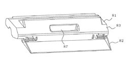
図3は塵埃回収ケース80の外観を示す斜視図である。図3に示すように、塵埃回収ケース80は、塵埃を溜める容器部81と、容器部81の下側の端部から延長された正面カバー部82を備える。正面カバー部82は、塵埃回収ケース80が空気調和機100の筐体10に取り付けられた場合に、空気調和機100の前面側を覆うような態様に形成されている。
容器部81には塵埃回収ケース80を空気調和機100の筐体10に取り付けたり、取り外したりする際に利用する凹形状の取手部87が形成されている。
ここで使用している正面カバー部82は、塵埃回収ケース80を構成する外側ケース81の一部からなり、容器部81と一体成形されたものであるが、正面カバー部82は容器部81の端部から延長された板状の別部材から形成してもよい。
FIG. 3 is a perspective view showing the appearance of the
The
The
ここでは、塵埃回収ケース80は外側ケース83と内側ケース84とから構成されており、外側ケース83が正面カバー部82となる部分も備えた形状となっている。
なお、外側ケース83と内側ケース84とを透明材から構成すると、移動中のフィルタ40が確認できるため、前面扉13を開けて作業中の作業者の安全が確保されやすい。
Here, the
If the
空気調和機100の前面にある前面扉13を開くと、その最前部には空間150が形成された状態となっている。従来、この空間150は熱交換器30への空気の吸い込み用開口部としていたものであるが、本実施の形態では、吸気口11を天面側に形成し、この空間150に、正面カバー部82を配置している。この正面カバー部82は、フィルタ40が天面側から前面側に移動した場合に、室内にいる人がフィルタ40に接触しないような形状とする。
When the
上記の空気調和機100においては、空気調和機100の動作時、例えば、予め定めた所定の間隔で、フィルタ移動機構部60が作動して、フィルタ40を、天面側から塵埃除去部70、塵埃回収ケース80、及び正面カバー部82に沿って円弧状に往復移動させる。このとき、塵埃除去部70がフィルタ40に当接し、フィルタ40から塵埃を剥離させてフィルタ40を清掃することで、剥離した塵埃が容器部81内に蓄えられる。なお、容器部81内に蓄えられた塵埃は、塵埃回収ケース80を外して回収することができる。
以上に説明した実施の形態1の空気調和機100及びそれに採用されているフィルタ清掃装置50によれば、フィルタ40の清掃時、空気調和機100の利用者がフィルタ40に容易には触れることがないため、空気調和機100の安全性やフィルタ40の耐久性が向上する。
In the
According to the
実施の形態2.
ここでは、フィルタ清掃装置50のフィルタ移動機構について説明する。図4はフィルタ清掃装置50のフィルタ移動機構を構成するフィルタ移動機構部60と、清掃対象であるフィルタ40の関係を示す斜視図、図5は図4のフィルタ移動機構部60の構成を説明するための模式図である。
フィルタ移動機構部60は、フィルタ40に形成されているフィルタ従動歯車45に噛み合うフィルタ駆動歯車61と、フィルタ駆動歯車61が略中央に固定されたフィルタ駆動軸62と、フィルタ駆動軸62の一方の端部に固定された回転力入力歯車63と、回転力入力歯車63及び回転力伝達歯車68を介してフィルタ駆動軸62に回転力を与える電動機64と、フィルタ駆動軸62を回転自在に支持するフィルタ移動機構部本体65とを備えている。
Embodiment 2. FIG.
Here, the filter moving mechanism of the
The filter
フィルタ移動機構部本体65には、フィルタ駆動軸62と平行に配置されて、フィルタ40を押圧するためのフィルタ押さえ軸66が設置されている。フィルタ押さえ軸66は例えば次のような態様に設置されている。すなわち、フィルタ押さえ軸66の両端部が、フィルタ移動機構部本体65に設けられた弾性部材67によって浮き上がり方向に付勢されて支持されており、フィルタ押さえ軸66をその上側から押圧することで、フィルタ押さえ軸66は弾性部材67の浮き上がり力に抗して、その押圧方向へ押しつけられる構造である。
The filter moving mechanism section
このフィルタ清掃装置50においては、筐体10に取り付けられている塵埃回収ケース80の内側ケースの一部が、フィルタ押さえ軸66を押圧するように配置されている。それにより、フィルタ押さえ軸66は弾性部材67の浮き上がり力に抗して、フィルタ40のフィルタ従動歯車45を、フィルタ駆動軸62に備えられているフィルタ駆動歯車61側へ押圧して、それらの歯車45,61を適切に噛み合わせる作用を果たしている。
In the
従って、塵埃回収ケース80から塵埃を回収するために、筐体10から塵埃回収ケース80を外した場合には、フィルタ押さえ軸66に対する押圧力が無くなり、フィルタ押さえ軸66は弾性部材67によって上方に押し上げられることになる。このため、フィルタ40に対するフィルタ押さえ軸66の押さえが無くなる。従って、樹脂等で成形されたフィルタ40はそれ自身の弾性力により手前に持ち上がり、フィルタ駆動歯車61とフィルタ従動歯車45との噛み合いが外れて、フィルタ40の移動が止まる。
このようにする事で、塵埃回収ケース80を外して塵埃を回収する作業中には、フィルタ40の移動が停止するため、作業者の安全性や作業性が確保できる。
なお、ここで説明したフィルタ移動機構部60の構成は一例であり、以上に説明したものと同等の作用を果たす他の機構を採用してもよいことは言うまでもない。
Therefore, when the
By doing so, the movement of the
Note that the configuration of the filter moving
10 筐体、11 吸気口、12 排気口、13 前面扉、20 送風ファン、30 熱交換器、40 フィルタ、40a フィルタの移動軌道、41 フィルタ通気体、42 フィルタ枠体、45 フィルタ従動歯車、50 フィルタ清掃装置、60 フィルタ移動機構部、61 フィルタ駆動歯車、62 フィルタ駆動軸、63 回転力入力歯車、64 電動機、65 フィルタ移動機構部筐体、66 フィルタ押さえ軸、67 弾性部材、68 回転力伝達歯車、70 塵埃除去部、80 塵埃回収ケース、81 容器部、82 正面カバー部、83 外側ケース、84 内側ケース、87 取手部、90 空間、100 空気調和機。
DESCRIPTION OF
Claims (9)
前記フィルタに当接して前記フィルタに捕捉された塵埃を除去する塵埃除去部と、
前記塵埃除去部によって除去された塵埃を蓄える容器部と移動されてきた前記フィルタを前記機器の前面側からカバーする正面カバー部とを有した塵埃回収部と、
前記フィルタを前記塵埃除去部および前記塵埃回収部に沿って往復移動させるフィルタ移動機構部と、を備え、
少なくとも前記塵埃回収部が前記機器の筐体に着脱自在に装着されること特徴とするフィルタ清掃装置。 Dust trapped in the filter is removed by moving the filter from a position corresponding to the air inlet to another position, which is attached to a device having an air inlet formed and provided with a filter corresponding to the air inlet. A filter cleaning device to be removed,
A dust removing unit that contacts the filter and removes the dust trapped by the filter;
A dust collecting section having a container section for storing the dust removed by the dust removing section and a front cover section for covering the moved filter from the front side of the device ;
A filter moving mechanism that reciprocates the filter along the dust removing unit and the dust collecting unit ,
At least the dust collection unit is detachably attached to the housing of the device.
前記塵埃回収部を前記筐体から外した場合には、前記弾性部材の弾性力により、前記フィルタ押さえ軸の前記フィルタ駆動歯車側への押圧力が解放される態様となっていることを特徴とする請求項5記載のフィルタ清掃装置。 While the dust collecting part is mounted on the housing, a part of the dust collecting part presses the filter holding shaft of the filter moving mechanism part against the filter driving gear side against the elastic force of the elastic member. And
When the dust collecting part is removed from the housing , the pressing force of the filter pressing shaft toward the filter driving gear is released by the elastic force of the elastic member. The filter cleaning apparatus according to claim 5.
前記フィルタ移動機構部が、
前記フィルタに設けられたフィルタ従動歯車に噛み合うフィルタ駆動歯車と、
前記フィルタ駆動歯車が固定されたフィルタ駆動軸と、
前記フィルタ駆動軸に回転力を与える電動機と、
前記フィルタ駆動軸と前記フィルタが通る隙間を隔てて配置され、前記フィルタ従動歯車を前記フィルタ駆動歯車に押圧するフィルタ押さえ軸と、を備え、
前記塵埃回収部は、前記フィルタの移動経路の途中位置において前記機器の筐体に着脱自在に設置されるものであり、
前記塵埃回収部が前記筐体に装着されている間は、前記塵埃回収部の一部が前記フィルタ押さえ軸を弾性部材の弾性力に抗して前記フィルタ駆動歯車側へ押圧し、
前記塵埃回収部が前記筐体から外された場合には、前記弾性部材の弾性力により前記フィルタ押さえ軸の前記フィルタ駆動歯車側への押圧力が解放され、前記フィルタ駆動歯車と前記フィルタ従動歯車との噛み合いが外れることを特徴とするフィルタ清掃装置。 A dust removing unit that is attached to a device equipped with a filter corresponding to the air inlet and that contacts the filter to remove dust trapped by the filter, and a container unit that stores the dust removed by the dust removing unit A dust collecting part having a front cover part that covers the moved filter from the front side of the device, and a filter moving mechanism part for reciprocating the filter along the dust removing part and the dust collecting part A filter cleaning device that removes dust trapped in the filter by moving the filter from a position corresponding to the air inlet to another position,
The filter moving mechanism is
A filter driving gear meshing with a filter driven gear provided in the filter;
A filter drive shaft to which the filter drive gear is fixed;
An electric motor for applying a rotational force to the filter drive shaft;
A filter pressing shaft that is disposed across a gap through which the filter drive shaft and the filter pass, and that presses the filter driven gear against the filter drive gear,
The dust collection unit is detachably installed in the housing of the device at a midway position in the movement path of the filter,
While the dust collecting part is mounted on the housing, a part of the dust collecting part presses the filter pressing shaft against the filter driving gear side against the elastic force of the elastic member ,
When the dust collecting part is removed from the housing, the pressing force of the filter pressing shaft toward the filter driving gear is released by the elastic force of the elastic member, and the filter driving gear and the filter driven gear are released. The filter cleaning device is characterized in that the engagement with is disengaged.
前記筐体内に設置され前記吸気口から空気を吸引する送風ファンと、
吸引された空気に含まれる塵埃を捕捉するフィルタと、
前記送風ファンが形成する風路内に設置され吸引された前記空気を調和する熱交換器と、
前記フィルタに付着した塵埃を清掃する請求項1〜7のいずれかに記載のフィルタ清掃装置と、
を具備したことを特徴とする空気調和機。 A housing in which an air inlet is formed;
A blower fan installed in the housing and sucking air from the intake port;
A filter for capturing dust contained in the sucked air;
A heat exchanger for harmonizing the sucked air installed in the air passage formed by the blower fan;
The filter cleaning device according to any one of claims 1 to 7, wherein dust attached to the filter is cleaned.
An air conditioner comprising:
Priority Applications (1)
| Application Number | Priority Date | Filing Date | Title |
|---|---|---|---|
| JP2006294416A JP4494388B2 (en) | 2006-10-30 | 2006-10-30 | Filter cleaning device and air conditioner |
Applications Claiming Priority (1)
| Application Number | Priority Date | Filing Date | Title |
|---|---|---|---|
| JP2006294416A JP4494388B2 (en) | 2006-10-30 | 2006-10-30 | Filter cleaning device and air conditioner |
Publications (3)
| Publication Number | Publication Date |
|---|---|
| JP2008111583A JP2008111583A (en) | 2008-05-15 |
| JP2008111583A5 JP2008111583A5 (en) | 2008-08-21 |
| JP4494388B2 true JP4494388B2 (en) | 2010-06-30 |
Family
ID=39444185
Family Applications (1)
| Application Number | Title | Priority Date | Filing Date |
|---|---|---|---|
| JP2006294416A Active JP4494388B2 (en) | 2006-10-30 | 2006-10-30 | Filter cleaning device and air conditioner |
Country Status (1)
| Country | Link |
|---|---|
| JP (1) | JP4494388B2 (en) |
Cited By (1)
| Publication number | Priority date | Publication date | Assignee | Title |
|---|---|---|---|---|
| CN109405091A (en) * | 2018-10-30 | 2019-03-01 | 四川长虹空调有限公司 | A kind of air-conditioning internal machine |
Families Citing this family (3)
| Publication number | Priority date | Publication date | Assignee | Title |
|---|---|---|---|---|
| JP5099030B2 (en) * | 2009-01-30 | 2012-12-12 | 株式会社富士通ゼネラル | Air conditioner |
| JP5498343B2 (en) * | 2010-10-05 | 2014-05-21 | 株式会社コロナ | Air conditioner |
| JP6068788B2 (en) * | 2011-10-04 | 2017-01-25 | 野崎 淳夫 | Pollutant cleaning device and pollutant cleaning control system using the same |
Citations (6)
| Publication number | Priority date | Publication date | Assignee | Title |
|---|---|---|---|---|
| JPH1147547A (en) * | 1997-08-05 | 1999-02-23 | Hitachi Ltd | Air-conditioner |
| JP2002250537A (en) * | 2002-02-26 | 2002-09-06 | Hitachi Ltd | Air conditioner |
| JP2004028487A (en) * | 2002-06-27 | 2004-01-29 | Fujitsu General Ltd | Air conditioner |
| JP2004044933A (en) * | 2002-07-12 | 2004-02-12 | Fujitsu General Ltd | Air conditioner |
| JP2005024134A (en) * | 2003-06-30 | 2005-01-27 | Fujitsu General Ltd | Air conditioner |
| JP2005155954A (en) * | 2003-11-21 | 2005-06-16 | Fujitsu General Ltd | Air conditioner |
Family Cites Families (1)
| Publication number | Priority date | Publication date | Assignee | Title |
|---|---|---|---|---|
| CN1906449B (en) * | 2004-10-27 | 2010-04-07 | 松下电器产业株式会社 | Air conditioner having indoor unit with automatic air filter cleaning function |
-
2006
- 2006-10-30 JP JP2006294416A patent/JP4494388B2/en active Active
Patent Citations (6)
| Publication number | Priority date | Publication date | Assignee | Title |
|---|---|---|---|---|
| JPH1147547A (en) * | 1997-08-05 | 1999-02-23 | Hitachi Ltd | Air-conditioner |
| JP2002250537A (en) * | 2002-02-26 | 2002-09-06 | Hitachi Ltd | Air conditioner |
| JP2004028487A (en) * | 2002-06-27 | 2004-01-29 | Fujitsu General Ltd | Air conditioner |
| JP2004044933A (en) * | 2002-07-12 | 2004-02-12 | Fujitsu General Ltd | Air conditioner |
| JP2005024134A (en) * | 2003-06-30 | 2005-01-27 | Fujitsu General Ltd | Air conditioner |
| JP2005155954A (en) * | 2003-11-21 | 2005-06-16 | Fujitsu General Ltd | Air conditioner |
Cited By (1)
| Publication number | Priority date | Publication date | Assignee | Title |
|---|---|---|---|---|
| CN109405091A (en) * | 2018-10-30 | 2019-03-01 | 四川长虹空调有限公司 | A kind of air-conditioning internal machine |
Also Published As
| Publication number | Publication date |
|---|---|
| JP2008111583A (en) | 2008-05-15 |
Similar Documents
| Publication | Publication Date | Title |
|---|---|---|
| JP4757730B2 (en) | Air conditioner | |
| JP5294440B2 (en) | Air conditioner | |
| JP4494388B2 (en) | Filter cleaning device and air conditioner | |
| KR20150125223A (en) | A cleaner | |
| JP4971757B2 (en) | Air conditioner indoor unit | |
| JP2009106908A5 (en) | ||
| JP4485509B2 (en) | Filter cleaning device and air conditioner | |
| JP2008104633A (en) | Apparatus provided with cleaning device and filter | |
| JP5720611B2 (en) | Air conditioning indoor unit | |
| JP4533366B2 (en) | Filter, filter cleaning device, and air conditioner | |
| JP2008111583A5 (en) | ||
| JP6037150B2 (en) | Air conditioner | |
| JP5765513B2 (en) | Air conditioner | |
| JP4755065B2 (en) | Air conditioner | |
| JP4428031B2 (en) | Air conditioner | |
| JP5118452B2 (en) | Air conditioner | |
| JP4928847B2 (en) | Vacuum cleaner | |
| TWI500530B (en) | Eraser machine | |
| JP6464019B2 (en) | Air cleaner | |
| JP2007117465A (en) | Dust collector and vacuum cleaner having the same | |
| JP5387855B2 (en) | Air conditioner | |
| JP4763574B2 (en) | Air conditioner | |
| JP5532221B2 (en) | Air conditioner | |
| JP2007155273A (en) | Filter cleaning device | |
| JP2008022933A (en) | Filter unit and vacuum cleaner using the filter unit |
Legal Events
| Date | Code | Title | Description |
|---|---|---|---|
| A521 | Request for written amendment filed |
Free format text: JAPANESE INTERMEDIATE CODE: A523 Effective date: 20080708 |
|
| A621 | Written request for application examination |
Free format text: JAPANESE INTERMEDIATE CODE: A621 Effective date: 20080708 |
|
| A977 | Report on retrieval |
Free format text: JAPANESE INTERMEDIATE CODE: A971007 Effective date: 20091029 |
|
| A131 | Notification of reasons for refusal |
Free format text: JAPANESE INTERMEDIATE CODE: A131 Effective date: 20091110 |
|
| A521 | Request for written amendment filed |
Free format text: JAPANESE INTERMEDIATE CODE: A523 Effective date: 20091215 |
|
| TRDD | Decision of grant or rejection written | ||
| A01 | Written decision to grant a patent or to grant a registration (utility model) |
Free format text: JAPANESE INTERMEDIATE CODE: A01 Effective date: 20100330 |
|
| A01 | Written decision to grant a patent or to grant a registration (utility model) |
Free format text: JAPANESE INTERMEDIATE CODE: A01 |
|
| A61 | First payment of annual fees (during grant procedure) |
Free format text: JAPANESE INTERMEDIATE CODE: A61 Effective date: 20100407 |
|
| R150 | Certificate of patent or registration of utility model |
Ref document number: 4494388 Country of ref document: JP Free format text: JAPANESE INTERMEDIATE CODE: R150 Free format text: JAPANESE INTERMEDIATE CODE: R150 |
|
| FPAY | Renewal fee payment (event date is renewal date of database) |
Free format text: PAYMENT UNTIL: 20130416 Year of fee payment: 3 |
|
| FPAY | Renewal fee payment (event date is renewal date of database) |
Free format text: PAYMENT UNTIL: 20130416 Year of fee payment: 3 |
|
| FPAY | Renewal fee payment (event date is renewal date of database) |
Free format text: PAYMENT UNTIL: 20140416 Year of fee payment: 4 |
|
| R250 | Receipt of annual fees |
Free format text: JAPANESE INTERMEDIATE CODE: R250 |
|
| R250 | Receipt of annual fees |
Free format text: JAPANESE INTERMEDIATE CODE: R250 |
|
| R250 | Receipt of annual fees |
Free format text: JAPANESE INTERMEDIATE CODE: R250 |
|
| R250 | Receipt of annual fees |
Free format text: JAPANESE INTERMEDIATE CODE: R250 |
|
| R250 | Receipt of annual fees |
Free format text: JAPANESE INTERMEDIATE CODE: R250 |
|
| R250 | Receipt of annual fees |
Free format text: JAPANESE INTERMEDIATE CODE: R250 |
|
| R250 | Receipt of annual fees |
Free format text: JAPANESE INTERMEDIATE CODE: R250 |
|
| R250 | Receipt of annual fees |
Free format text: JAPANESE INTERMEDIATE CODE: R250 |