JP4491943B2 - Optical disk drive and optical disk identification method - Google Patents
Optical disk drive and optical disk identification method Download PDFInfo
- Publication number
- JP4491943B2 JP4491943B2 JP2000289348A JP2000289348A JP4491943B2 JP 4491943 B2 JP4491943 B2 JP 4491943B2 JP 2000289348 A JP2000289348 A JP 2000289348A JP 2000289348 A JP2000289348 A JP 2000289348A JP 4491943 B2 JP4491943 B2 JP 4491943B2
- Authority
- JP
- Japan
- Prior art keywords
- signal
- optical disc
- optical disk
- level
- disc
- Prior art date
- Legal status (The legal status is an assumption and is not a legal conclusion. Google has not performed a legal analysis and makes no representation as to the accuracy of the status listed.)
- Expired - Fee Related
Links
Images


Classifications
-
- G—PHYSICS
- G11—INFORMATION STORAGE
- G11B—INFORMATION STORAGE BASED ON RELATIVE MOVEMENT BETWEEN RECORD CARRIER AND TRANSDUCER
- G11B19/00—Driving, starting, stopping record carriers not specifically of filamentary or web form, or of supports therefor; Control thereof; Control of operating function ; Driving both disc and head
- G11B19/02—Control of operating function, e.g. switching from recording to reproducing
- G11B19/12—Control of operating function, e.g. switching from recording to reproducing by sensing distinguishing features of or on records, e.g. diameter end mark
Description
【0001】
【発明の属する技術分野】
この発明は、例えばDVD−RW、DVD+RW、DVD−ROMなどの光ディスクが装着される光ディスクドライブおよび光ディスク判別方法に関する。詳しくは、装着された光ディスクより再生されたグルーブウォブルに対応する信号より記録可能な複数種類の光ディスクのグルーブウォブルの周波数に対応した複数の周波数成分をそれぞれ抽出し、抽出された複数の周波数成分に基づいて、装着された光ディスクが記録可能な光ディスクであるか否かの判定を行うことによって、装着された光ディスクが記録可能な光ディスクであるか否かを、短時間かつ確実に判定し得るようにした光ディスクドライブ等に係るものである。
【0002】
【従来の技術】
DVD系の光ディスクとして、DVD−RWディスク、DVD+RWディスク等の記録可能な光ディスクがあると共に、DVD−ROMディスク等の再生専用の光ディスクがある。これらのDVD系の光ディスクは、直径が12cmであって外形が同一とされている。また、DVD系の光ディスクドライブとして、記録再生を行う光ディスク記録再生装置や再生のみを行う光ディスク再生装置がある。
【0003】
【発明が解決しようとする課題】
上述したようにDVD系の光ディスクは外形が同一であることから、上述したDVD系の光ディスク記録再生装置や光ディスク再生装置には特性等が異なる数種類の光ディスクが装着されることとなる。したがって、装置側では、装着された光ディスクの判定をし、その判定結果に基づいて装着された光ディスクを取り扱うことが必要となる。
【0004】
例えば、複製禁止のディジタルビデオ信号が複製禁止を無視して記録された記録可能な光ディスクが装着された場合、その光ディスクが記録可能な光ディスクであると判定して、その光ディスクからは、記録されているディジタルビデオ信号の再生を行わないようにする。
【0005】
そこで、この発明では、装着された光ディスクが記録可能な光ディスクであるか否かを、短時間かつ確実に判定し得る光ディスクドライブ等を提供することを目的とする。
【0006】
【課題を解決するための手段】
上記課題を解決し、本発明の目的を達成するため、本発明の光ディスクドライブは、装着された光ディスクを所定の回転速度で回転させた状態で、光ディスクの半径方向の所定位置より、グルーブウォブルに対応した信号を再生するウォブル信号再生手段と、ウォブル信号再生手段の出力信号より、記録可能な複数種類の光ディスクのグルーブウォブルの周波数に対応した複数の周波数成分を抽出する複数のフィルタ手段と、この複数のフィルタ手段の出力信号の振幅レベルもしくは周波数レベルを検出する検出手段と、検出手段の検出信号を用いて上記装着された光ディスクの判別をするディスク判別手段と、を備える。
そして、この検出手段で、複数のフィルタ手段の出力信号の振幅レベルをそれぞれ検出し、検出手段で検出された第1の信号の振幅レベルが、第2の信号の振幅レベルより大きく、かつ所定の閾値より大きい場合に、ディスク判別手段は、その光ディスクを第1の光ディスクであると判別する。また、検出手段で検出された第2の信号の振幅レベルが、第1の信号の振幅レベルより大きく、かつ所定の閾値より大きい場合に、ディスク判別手段は、その光ディスクを第2の光ディスクであると判別する。そして、検出手段で検出された第1の信号の振幅レベル及び第2の信号の振幅レベルが、いずれも所定の閾値より低い場合には、ディスク判別手段は、光ディスクが第3の光ディスクであると判別する。
【0007】
また、本発明の光ディスク判別方法は、装着された光ディスクを所定の回転速度で回転させた状態で、光ディスクの半径方向の所定位置より、グルーブウォブルに対応した信号を再生する工程と、この再生された信号から、記録可能な複数種類の光ディスクのグルーブウォブルの周波数に対応した複数の周波数成分を複数のフィルタ手段によりそれぞれ抽出する工程と、この複数のフィルタ手段で抽出されたそれぞれの周波数成分の振幅レベルを検出する工程と、検出した複数の周波数成分の振幅レベルにより、装着された光ディスクを判別する工程と、を含む。
そして、この光ディスクを判別する工程において、複数のフィルタ手段の出力信号の振幅レベルの中で、第1の信号の振幅レベルが、第2の信号の振幅レベルより大きく、かつ所定の閾値より大きいと検出された場合に、装着されている光ディスクを第1の光ディスクであると判別し、複数のフィルタ手段の出力信号の振幅レベルの中で、第2の信号の振幅レベルが、第1の信号の振幅レベルより大きく、かつ所定の閾値より大きいと検出された場合に、装着されている光ディスクが第2の光ディスクであると判別する。また、複数のフィルタ手段の出力信号の振幅レベルの中で、第1の信号の振幅レベル及び第2の信号の振幅レベルのいずれも所定の閾値より低いと検出された場合には、装着されている光ディスクが第3の光ディスクであると判別する。
【0008】
この発明においては、記録可能な複数種類の光ディスクおよび再生専用の光ディスクの装着が可能とされる。記録可能なある種類の光ディスクが装着される場合には、再生されたグルーブウォブルに対応した信号は、その光ディスクのグルーブウォブルの周波数に対応した周波数成分のレベルが大きなものとなる。
【0009】
例えば、光ディスクを1389rpmで回転駆動し、この光ディスクの半径24mmの位置を再生して信号を得るものとすると、その信号は、DVD−RWディスクが装着されている場合には約140kHzの周波数成分のレベルが大きなものとなり、DVD+RWディスクが装着されている場合には約810kHzの周波数成分のレベルが大きなものとなる。
【0010】
このように再生されたグルーブウォブルに対応した信号より、記録可能な複数種類の光ディスクのグルーブウォブルの周波数に対応した複数の周波数成分がそれぞれ抽出される。例えば、記録可能な複数種類の光ディスクがDVD−RWディスク、DVD+RWディスクである場合には、約140kHzの周波数成分と、約810kHzの周波数成分が抽出される。
【0011】
そして、これら抽出された複数の周波数成分に基づいて、装着された光ディスクが記録可能な光ディスクであるか否かが判定される。この場合、複数の周波数成分のいずれかのレベルが大きいときには、その周波数成分に対応した記録可能な光ディスクが装着されていることが分かる。また、複数の周波数成分のいずれのレベルも大きくないときは、記録可能な複数種類の光ディスクのいずれも装着されていないことが分かる。
【0012】
このように、装着された光ディスクより再生されたグルーブウォブルに対応する信号より記録可能な複数種類の光ディスクのグルーブウォブルの周波数に対応した複数の周波数成分をそれぞれ抽出し、抽出された複数の周波数成分に基づいて、装着された光ディスクが記録可能な光ディスクであるか否かの判定を行うことにより、装着された光ディスクが記録可能な光ディスクであるか否かを短時間かつ確実に判定することが可能となる。
【0013】
【発明の実施の形態】
以下、図面を参照しながら、この発明の実施の形態について説明する。図1は、DVD系の光ディスクの装着が可能な光ディスクドライブ100の一部の構成を示している。
【0014】
ドライブ100は、装着された光ディスク101を回転駆動するためのスピンドルモータ102と、半導体レーザ、対物レンズ、フォトディテクタ等から構成される光ピックアップ103と、この光ピックアップ103を光ディスク101の半径方向(ラジアル方向)に移動させるための送りモータ104とを有している。この場合、光ピックアップ103を構成する半導体レーザからのレーザビームが光ディスク101の記録面に照射され、その反射光(戻り光)が光ピックアップ103を構成するフォトディテクタに照射される。
【0015】
また、ドライブ100は、ドライブ全体の動作を制御するコントローラ105と、サーボコントローラ106とを有している。コントローラ105には、液晶表示素子等で構成される表示部107および複数の操作キーが配された操作キー部108が接続されている。サーボコントローラ106は、光ピックアップ103におけるトラッキングやフォーカスを制御し、また送りモータ104の動作を制御する。さらに、サーボコントローラ106はスピンドルモータ102の回転を制御し、光ディスク101は、記録時や再生時には、CLV(Constant Linear Velocity)で回転駆動される。
【0016】
また、ドライブ100は、光ピックアップ103を構成するフォトディテクタの出力信号を処理して再生RF信号SRF、フォーカスエラー信号SFE、トラッキングエラー信号STEおよびプッシュプル信号SPPを作成するRFアンプ部109を有している。ここで、フォーカスエラー信号SFEは、アスティグマ法(非点収差法)によって作成される。また、トラッキングエラー信号STEは、再生時にはDPD法(位相差法)によって作成され、記録時にはプッシュプル法によって作成される。
【0017】
このようにRFアンプ部109で作成されるフォーカスエラー信号SFEおよびトラッキングエラー信号STEはサーボコントローラ106に供給され、このサーボコントローラ106では、これらのエラー信号を用いて、上述したように光ピックアップ103におけるトラッキングやフォーカスを制御する。
【0018】
ここで、光ピックアップ103を構成するフォトディテクタとして、図2に示すように、4分割フォトディテクタPDが用いられている。このフォトディテクタPDには、光ディスク101からの戻り光によるスポットSPが形成される。フォトディテクタPDを構成する4個のフォトダイオードDa〜Ddの検出信号をSa〜Sdとするとき、プッシュプル信号SPPは、以下の演算によって得られる。
【0019】
すなわち、検出信号Sa,Scが加算器111で加算されると共に、検出信号Sb,Sdが加算器112で加算される。そして、減算器113で加算器111の出力信号より加算器112の出力信号が減算されて、プッシュプル信号SPPが得られる。
【0020】
また、図1に戻って、ドライブ100は、RFアンプ部109で作成された再生RF信号の2値化スライス、その後のPLL(Phase-Locked Loop)による同期データの生成等、一連のアナログ信号処理を行うリードチャネル部115と、リードチャネル部108で生成された同期データ(8/16変調データ)の復調、その後の誤り訂正等の処理を行う復調/ECC部109とを有している。この復調/ECC部109の出力データは、図示しない再生データ処理系に供給される。
【0021】
また、ドライブ100は、再生RF信号SRFよりリードチャネル部115で抽出されるアドレス情報をコントローラ105に転送したり、プッシュプル信号SPPを処理してアドレス情報を得て、このアドレス情報をコントローラ105に転送するアドレス処理部117を有している。
【0022】
また、ドライブ100は、RFアンプ部109で作成されたプッシュプル信号SPPよりウォブル信号を検出するウォブル検出部118を有している。図3は、このウォブル検出部118の構成を示している。
【0023】
ウォブル検出部118は、中心周波数f1が140kHzであるバンドパスフィルタ121と、中心周波数f2が810kHzであるバンドパスフィルタ122とを有している。
【0024】
なお、光ディスク101がDVD−RWディスクである場合、この光ディスク101を1389rpmで回転駆動した場合、光ディスク101の半径24mmの位置におけるグルーブウォブルの周波数は約140kHzとなる。したがって、この場合におけるプッシュプル信号SPPは、約140kHzの周波数成分のレベルが大きなものとなる。
【0025】
また、光ディスク101がDVD+RWディスクである場合、この光ディスク101を1389rpmで回転駆動した場合、光ディスク101の半径24mmの位置におけるグルーブウォブルの周波数は約810kHzとなる。したがって、この場合におけるプッシュプル信号SPPは、約810kHzの周波数成分のレベルが大きなものとなる。
【0026】
また、ウォブル検出部118は、バンドパスフィルタ121の出力信号SF1の振幅レベルを検出するレベル検出部123と、バンドパスフィルタ122の出力信号SF2の振幅レベルを検出するレベル検出部124とを有している。これらレベル検出部123,124は、例えば整流平滑回路で構成されている。
【0027】
また、ウォブル検出部118は、レベル検出部123の出力信号を、コントローラ105より所定のタイミングで供給されるサンプルパルスSMPでサンプリングし、そのサンプル値を検出レベルLV1としてホールドするサンプルホールド回路125と、レベル検出部124の出力信号を、上述のサンプルパルスSMPでサンプリングし、そのサンプル値を検出レベルLV2としてホールドするサンプルホールド回路126とを有している。
【0028】
また、ウォブル検出部118は、サンプルホールド回路125でホールドされた検出レベルLV1をディジタル信号に変換してコントローラ105に供給するA/Dコンバータ127と、サンプルホールド回路126でホールドされた検出レベルLV2をディジタル信号に変換してコントローラ105に供給するA/Dコンバータ128とを有している。
【0029】
図1に示す光ディスクドライブ100におけるディスク判定動作について説明する。コントローラ105は、光ディスク101が装着される際に、この光ディスク101が、記録可能なディスク、すなわちDVD−RWディスクまたはDVD+RWディスクであるか、あるいは再生専用のディスク、すなわちDVD−ROMディスクであるかを判定する。
【0030】
この場合、コントローラ105は、サーボコントローラ106を制御し、光ピックアップ103を半径24mmの位置に移動させ、光ディスク101を1389rpmで回転駆動させ、光ピックアップ103で半導体レーザよりレーザビームを発光させ、さらにフォーカスやトラッキングのサーボを行わせる。この状態で、RFアンプ部109で作成されるプッシュプル信号SPPはウォブル検出部118(図2参照)に供給される。ウォブル検出部118では、プッシュプル信号SPPが処理されて検出レベルLV1,LV2が生成され、この検出レベルLV1,LV2がコントローラ105に供給される。
【0031】
すなわち、プッシュプル信号SPPより、バンドパスフィルタ121で、約140kHzの周波数成分が抽出される。そして、このフィルタ121の出力信号SF1の振幅レベルがレベル検出部123で検出され、さらにレベル検出部123の出力信号がサンプルホールド回路125でサンプリングされて検出レベルLV1が得られる。そして、この検出レベルLV1が、A/Dコンバータ127でディジタル信号に変換されてコントローラ105に供給される。
【0032】
同様に、プッシュプル信号SPPより、バンドパスフィルタ122で、約810kHzの周波数成分が抽出される。そして、このフィルタ122の出力信号SF2の振幅レベルがレベル検出部124で検出され、さらにそのレベル検出部124の出力信号がサンプルホールド回路126でサンプリングされて検出レベルLV2が得られる。この検出レベルLV2が、A/Dコンバータ128でディジタル信号に変換されてコントローラ105に供給される。
【0033】
コントローラ105では、検出レベルLV1,LV2を用いて、装着された光ディスク101の判定が、以下のように行われる。すなわち、LV1>LV2であって、LV1が規定レベル以上であるとき、装着された光ディスク101は、記録可能なディスクであるDVD−RWディスクであると判定される。また、LV2>LV1であって、LV2が規定レベル以上であるとき、装着された光ディスク101は、記録可能なディスクであるDVD+RWディスクであると判定される。さらに、LV1,LV2の双方が規定レベルより小さいとき、装着された光ディスク101は、再生専用のディスクであるDVD−ROMディスクであると判定される。このような判定結果は、コントローラ105の制御で、例えば表示部107に表示され、ユーザに報知される。
【0034】
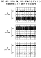
ここで、光ディスク101としてDVD−RWディスクが装着される場合、プッシュプル信号SPPは約140kHzの周波数成分のレベルが大きなものとなるため、バンドパスフィルタ121の出力信号SF1およびバンドパスフィルタ122の出力信号SF2は、図4Aに示すように得られる(例えばSF1は180mVp-p、SF2は30mVp-p)。したがって、この場合には、LV1>LV2であって、LV1が規定レベル以上となるため(規定レベルは、例えば100mVp-pに対応するレベル)、DVD−RWディスクが装着されていると判定されることとなる。
【0035】
また、光ディスク101としてDVD+RWディスクが装着される場合、プッシュプル信号SPPは約810kHzの周波数成分のレベルが大きなものとなるため、バンドパスフィルタ121の出力信号SF1およびバンドパスフィルタ122の出力信号SF2は、図4Bに示すように得られる(例えばSF1は30mVp-p、SF2は200mVp-p)。したがって、この場合には、LV2>LV1であって、LV2が規定レベル以上となるため、DVD+RWディスクが装着されていると判定されることとなる。
【0036】
さらに、光ディスク101としてDVD−ROMディスクが装着される場合、プッシュプル信号SPPは約140kHzおよび約810kHzの周波数成分の双方のレベルが小さいものとなるため、バンドパスフィルタ121の出力信号SF1およびバンドパスフィルタ122の出力信号SF2は、図4Cに示すように得られる。したがって、この場合には、LV1,LV2の双方が規定レベルより小さくなるため、DVD−ROMディスクが装着されていると判定されることとなる。
【0037】
以上説明したように、本実施の形態においては、ウォブル検出部118で、バンドパスフィルタ121,122によって、プッシュプル信号SPPより、DVD−RWディスク,DVD+RWディスクのグルーブウォブルの周波数成分がそれぞれ抽出される。そして、このウォブル検出部118よりコントローラ105に、抽出されたそれぞれの周波数成分の振幅レベルに対応した検出レベルLV1,LV2が供給される。そして、コントローラ105では、この検出レベルLV1,LV2に基づいて、装着された光ディスク101の判定が行われる。
【0038】
したがって、本実施の形態においては、装着された光ディスク101がDVD−RWディスクであるかの判定と、装着された光ディスク101がDVD+RWディスクであるかの判定とを並行して行うものであり、装着された光ディスク101が記録可能な光ディスク(DVD−RWディスク,DVD+RWディスク)であるか否かを、短時間かつ確実に判定することができる。これにより、例えば、複製禁止のディジタルビデオ信号が複製禁止を無視して記録可能なディスクに記録されていても、そのことを即座に判断できるようになる。
【0039】
また、本実施の形態においては、装着された光ディスク101が記録可能な光ディスクである場合、その種類を同時に知ることができる。これにより、誤って対応できない光ディスクに記録しようとしてしまう可能性を低減できる。
【0040】
なお、上述実施の形態において、ウォブル検出部118は、図3に示すように構成されていたが、図5に示すように構成してもよい。この図5において、図3と対応する部分には同一符号を付し、その詳細説明は省略する。
【0041】
このウォブル検出部118は、図3に示すウォブル検出部118と同様に、中心周波数f1が140kHzであるバンドパスフィルタ121と、中心周波数f2が810kHzであるバンドパスフィルタ122とを有している。
【0042】
また、このウォブル検出部118は、バンドパスフィルタ121の出力信号SF1を2値化する2値化回路131と、バンドパスフィルタ122の出力信号SF2を2値化する2値化回路132と、2値化回路131からの2値化信号を参照信号として周波数信号FO1を生成し、この周波数信号FO1をコントローラ105に供給するPLL回路133と、2値化回路132からの2値化信号を参照信号として周波数信号FO2を生成し、この周波数信号FO2をコントローラ105に供給するPLL回路134とを有している。
【0043】
装着された光ディスク101の判定動作を行う際に、ウォブル検出部118では、プッシュプル信号SPPが処理されて、周波数信号FO1,FO2が生成され、この周波数信号FO1,FO2がコントローラ105に供給される。
【0044】
すなわち、プッシュプル信号SPPより、バンドパスフィルタ121で、約140kHzの周波数成分が抽出される。そして、このフィルタ121の出力信号SF1が2値化回路131で2値化され、この2値化回路131からの2値化信号がPLL回路133に参照信号として供給される。そして、このPLL回路133より出力される周波数信号FO1がコントローラ105に供給される。
【0045】
この場合、バンドパスフィルタ121の出力信号SF1における約140kHzの周波数成分のレベルが大きいとき、PLL回路133に供給される2値化信号は約140kHzの単一周波数を持つものとなり、周波数信号FO1として約140kHzの周波数信号が得られる。これに対して、バンドパスフィルタ121の出力信号SF1における約140kHzの周波数成分のレベルが小さいとき、ノイズ成分のためにPLL回路133に供給される2値化信号は約140kHzの単一周波数を持つものとはならず、周波数信号FO1として約140kHzの周波数信号は得られない。
【0046】
同様に、プッシュプル信号SPPより、バンドパスフィルタ122で、約810kHzの周波数成分が抽出される。そして、このフィルタ122の出力信号SF1が2値化回路132で2値化され、この2値化回路132からの2値化信号がPLL回路134に参照信号として供給される。そして、このPLL回路134より出力される周波数信号FO2がコントローラ105に供給される。
【0047】
この場合、バンドパスフィルタ122の出力信号SF1における約810kHzの周波数成分のレベルが大きいとき、PLL回路134に供給される2値化信号は約810kHzの単一周波数を持つものとなり、周波数信号FO2として約810kHzの周波数信号が得られる。これに対して、バンドパスフィルタ122の出力信号SF2における約810kHzの周波数成分のレベルが小さいとき、ノイズ成分のためにPLL回路134に供給される2値化信号は約810kHzの単一周波数を持つものとはならず、周波数信号FO2として約810kHzの周波数信号は得られない。
【0048】
コントローラ105では、周波数信号FO1,FO2を用いて、装着された光ディスク101の判定が、以下のように行われる。すなわち、周波数信号FO1が約140kHzの周波数信号であるとき、装着された光ディスク101は、記録可能なディスクであるDVD−RWディスクであると判定される。また、周波数信号FO2が約810kHzの周波数信号であるとき、装着された光ディスク101は、記録可能なディスクであるDVD+RWディスクであると判定される。さらに、周波数信号FO1が約140kHzの周波数信号でもなく、周波数信号FO2が約810kHzの周波数信号でもないとき、装着された光ディスク101は、再生専用のディスクであるDVD−ROMディスクであると判定される。
【0049】
コントローラ105では、周波数信号FO1,FO2の周波数の判断を、例えば水晶精度のクロックを使用し、周波数信号FO1,FO2の周期をカウントすることで行う。例えば、周波数信号FO2の周期を100MHzのクロックでカウントしたとき、118〜129の範囲のカウントであれば、周波数信号FO2の周波数は775.2kHz〜847.5kHzであり、810kHzの±5%以内にあることから、コントローラ105は周波数信号FO2の周波数が約810kHzであると判断する。±5%の幅を持たせるのは、光ディスク101における測定個所、回転数等の較差を考慮したものである。なお、詳細な数値は示さないが、周波数信号FO1の周波数を判断する際にも、同様に±5%の幅を持たせる。
【0050】
ここで、光ディスク101としてDVD−RWディスクが装着される場合、プッシュプル信号SPPは約140kHzの周波数成分のレベルが大きなものとなるため、バンドパスフィルタ121の出力信号SF1およびバンドパスフィルタ122の出力信号SF2は、図4Aに示すように得られる。したがって、この場合には、周波数信号FO1が約140kHzの周波数信号となるため、DVD−RWディスクが装着されていると判定されることとなる。
【0051】
また、光ディスク101としてDVD+RWディスクが装着される場合、プッシュプル信号SPPは約810kHzの周波数成分のレベルが大きなものとなるため、バンドパスフィルタ121の出力信号SF1およびバンドパスフィルタ122の出力信号SF2は、図4Bに示すように得られる。したがって、この場合には、周波数信号FO2が約810kHzの周波数信号となるため、DVD+RWディスクが装着されていると判定されることとなる。
【0052】
さらに、光ディスク101としてDVD−ROMディスクが装着される場合、プッシュプル信号SPPは約140kHzおよび約810kHzの周波数成分のレベルが小さいものとなるため、バンドパスフィルタ121の出力信号SF1およびバンドパスフィルタ122の出力信号SF2は、図4Cに示すように得られる。したがって、この場合には、周波数信号FO1が約140kHzの周波数信号とならず、また周波数信号FO2が約810kHzの周波数信号とならず、DVD−ROMディスクが装着されていると判定されることとなる。
【0053】
また、上述実施の形態においては、記録可能な2種類の光ディスク(DVD−RW,DVD+RW)を並行して判定するものを示したが、同様にして、記録可能な複数種類の光ディスクを並行して判定することができる。ただしこの場合、複数種類の光ディスクは互いにグルーブウォブルの周波数が異なっている必要がある。
【0054】
また、上述実施の形態においては、この発明を、DVD系の光ディスクドライブ100に適用したものであるが、この発明は、CD系の光ディスクドライブ等にも同様に適用できることは勿論である。
【0055】
【発明の効果】
この発明によれば、装着された光ディスクより再生されたグルーブウォブルに対応する信号より記録可能な複数種類の光ディスクのグルーブウォブルの周波数に対応した複数の周波数成分をそれぞれ抽出し、抽出された複数の周波数成分に基づいて、装着された光ディスクが記録可能な光ディスクであるか否かの判定を行うものであり、装着された光ディスクが記録可能な光ディスクであるか否かを短時間かつ確実に判定できる。
【図面の簡単な説明】
【図1】光ディスクドライブの一部の構成を示すブロック図である。
【図2】プッシュプル信号の作成を説明するための図である。
【図3】ウォブル検出部の構成を示すブロック図である。
【図4】DVD−RW,DVD+RW,DVD−ROMの各ディスクの装着時におけるバンドパスフィルタの出力信号を示す図である。
【図5】ウォブル検出部の他の構成を示すブロック図である。
【符号の説明】
100・・・光ディスクドライブ、101・・・光ディスク、103・・・光ピックアップ、105・・・コントローラ、106・・・サーボコントローラ、107・・・表示部、109・・・RFアンプ部、115・・・リードチャネル部、116・・・復調/ECC部、117・・・アドレス処理部、118・・・ウォブル検出部、121,122・・・バンドパスフィルタ、123,124・・・レベル検出部、125,126・・・サンプルホールド回路、127,128・・・A/Dコンバータ、131,132・・・2値化回路、133,134・・・PLL回路[0001]
BACKGROUND OF THE INVENTION
The present invention relates to an optical disc drive to which an optical disc such as DVD-RW, DVD + RW, DVD-ROM, etc. is mounted and an optical disc discrimination method . Specifically, a plurality of frequency components corresponding to the groove wobble frequencies of a plurality of types of optical discs that can be recorded are extracted from signals corresponding to the groove wobble reproduced from the mounted optical disc, and the extracted plurality of frequency components are extracted. Based on this, it is determined whether or not the mounted optical disc is a recordable optical disc by determining whether or not the mounted optical disc is a recordable optical disc. This relates to the optical disk drive and the like.
[0002]
[Prior art]
As DVD-type optical discs, there are recordable optical discs such as DVD-RW discs and DVD + RW discs, and there are read-only optical discs such as DVD-ROM discs. These DVD optical disks have a diameter of 12 cm and the same outer shape. As DVD-type optical disk drives, there are an optical disk recording / reproducing apparatus that performs recording and reproduction and an optical disk reproducing apparatus that performs only reproduction.
[0003]
[Problems to be solved by the invention]
As described above, since the DVD-type optical disc has the same outer shape, several types of optical discs having different characteristics and the like are mounted on the above-described DVD-type optical disc recording / playback apparatus and optical disc playback apparatus. Therefore, the apparatus side needs to determine the mounted optical disk and handle the mounted optical disk based on the determination result.
[0004]
For example, if a recordable optical disc recorded with a copy-prohibited digital video signal ignoring copy-prohibition is installed, it is determined that the optical disc is a recordable optical disc and is recorded from the optical disc. The digital video signal is not reproduced.
[0005]
Therefore, an object of the present invention is to provide an optical disk drive or the like that can determine whether or not the loaded optical disk is a recordable optical disk in a short time.
[0006]
[Means for Solving the Problems]
In order to solve the above-described problems and achieve the object of the present invention, the optical disk drive of the present invention has a groove wobble from a predetermined position in the radial direction of the optical disk in a state where the loaded optical disk is rotated at a predetermined rotation speed. a wobble signal reproducing means for reproducing the corresponding signals, and a plurality of filter means to extract from the output signal of the wobble signal reproduction means, a plurality of frequency components corresponding to the frequency of the groove wobble recordable plurality of types of optical discs, And a detection means for detecting the amplitude level or frequency level of the output signals of the plurality of filter means, and a disc discrimination means for discriminating the mounted optical disc using the detection signal of the detection means.
Then, the detection means detects the amplitude levels of the output signals of the plurality of filter means, respectively, and the amplitude level of the first signal detected by the detection means is larger than the amplitude level of the second signal and has a predetermined value. If it is larger than the threshold value, the disc discriminating unit discriminates that the optical disc is the first optical disc. Further, when the amplitude level of the second signal detected by the detection means is greater than the amplitude level of the first signal and greater than a predetermined threshold value, the disc determination means uses the optical disc as the second optical disc. Is determined. When the amplitude level of the first signal and the amplitude level of the second signal detected by the detection unit are both lower than the predetermined threshold, the disc determination unit determines that the optical disc is the third optical disc. Determine.
[0007]
The optical disc discrimination method of the present invention includes a step of reproducing a signal corresponding to the groove wobble from a predetermined position in the radial direction of the optical disc in a state where the loaded optical disc is rotated at a predetermined rotational speed, from the signal, the steps of extracting each of a plurality of filter means a plurality of frequency components corresponding to the frequency of the groove wobble recordable plurality of types of optical disks, the amplitude of each frequency component extracted by the plurality of filter means A step of detecting a level, and a step of discriminating a mounted optical disc based on the detected amplitude levels of a plurality of frequency components.
In the step of discriminating the optical disk, if the amplitude level of the first signal is greater than the amplitude level of the second signal among the amplitude levels of the output signals of the plurality of filter means, and greater than a predetermined threshold value. If detected, it is determined that the mounted optical disk is the first optical disk, and among the amplitude levels of the output signals of the plurality of filter means, the amplitude level of the second signal is equal to that of the first signal. When it is detected that it is larger than the amplitude level and larger than the predetermined threshold value, it is determined that the mounted optical disk is the second optical disk. In addition, when it is detected that both the amplitude level of the first signal and the amplitude level of the second signal are lower than a predetermined threshold among the amplitude levels of the output signals of the plurality of filter means, it is attached. It is determined that the existing optical disk is the third optical disk.
[0008]
In the present invention, it is possible to mount a plurality of types of recordable optical discs and a read-only optical disc. When a recordable optical disc of a certain type is loaded, the signal corresponding to the reproduced groove wobble has a high level of the frequency component corresponding to the frequency of the groove wobble of the optical disc.
[0009]
For example, when an optical disk is driven to rotate at 1389 rpm and a signal is obtained by reproducing the position of a radius of 24 mm of the optical disk, the signal has a frequency component of about 140 kHz when a DVD-RW disk is mounted. When the DVD + RW disc is mounted, the level of the frequency component of about 810 kHz becomes large.
[0010]
A plurality of frequency components corresponding to the frequency of the groove wobble of a plurality of types of recordable optical discs are extracted from the signal corresponding to the groove wobble reproduced in this way. For example, when the plural types of recordable optical discs are DVD-RW discs and DVD + RW discs, a frequency component of about 140 kHz and a frequency component of about 810 kHz are extracted.
[0011]
Then, based on the plurality of extracted frequency components, it is determined whether or not the mounted optical disc is a recordable optical disc. In this case, when the level of any one of the plurality of frequency components is high, it can be seen that a recordable optical disc corresponding to the frequency component is loaded. Further, when none of the levels of the plurality of frequency components is high, it can be understood that none of the plural types of recordable optical disks is loaded.
[0012]
In this way, a plurality of frequency components corresponding to the groove wobble frequencies of a plurality of types of optical discs that can be recorded are extracted from a signal corresponding to the groove wobble reproduced from the mounted optical disc, and the plurality of extracted frequency components Based on the above, it can be determined in a short time and reliably whether or not the mounted optical disk is a recordable optical disk by determining whether or not the mounted optical disk is a recordable optical disk It becomes.
[0013]
DETAILED DESCRIPTION OF THE INVENTION
Hereinafter, embodiments of the present invention will be described with reference to the drawings. FIG. 1 shows a configuration of a part of an
[0014]
The
[0015]
The
[0016]
Further, the
[0017]
The focus error signal S FE and the tracking error signal S TE which are created by the
[0018]
Here, as shown in FIG. 2, a four-divided photodetector PD is used as the photodetector constituting the optical pickup 103. On this photodetector PD, a spot SP is formed by the return light from the
[0019]
That is, the detection signals Sa and Sc are added by the adder 111 and the detection signals Sb and Sd are added by the
[0020]
Returning to FIG. 1, the
[0021]
Further, the
[0022]
The
[0023]
The
[0024]
When the
[0025]
When the
[0026]
The
[0027]
The
[0028]
The
[0029]
A disc determination operation in the
[0030]
In this case, the
[0031]
That is, from the push-pull signal S PP, the band-
[0032]
Similarly, a frequency component of about 810 kHz is extracted from the push-pull signal SPP by the
[0033]
In the
[0034]
Here, if the DVD-RW disk is mounted as the
[0035]
Also, if the DVD + RW disk is mounted as the
[0036]
Moreover, if the DVD-ROM disk is mounted as the
[0037]
As described above, in the present embodiment, in the
[0038]
Therefore, in the present embodiment, determination as to whether or not the mounted
[0039]
In the present embodiment, when the mounted
[0040]
In the above-described embodiment, the
[0041]
Similar to the
[0042]
The
[0043]
When performing the determination operation of the mounted
[0044]
That is, from the push-pull signal S PP, the band-
[0045]
In this case, when the level of the frequency component of about 140 kHz in the output signal SF1 of the
[0046]
Similarly, a frequency component of about 810 kHz is extracted from the push-pull signal SPP by the
[0047]
In this case, when the level of the frequency component of about 810 kHz in the output signal SF1 of the
[0048]
In the
[0049]
The
[0050]
Here, if the DVD-RW disk is mounted as the
[0051]
Also, if the DVD + RW disk is mounted as the
[0052]
Moreover, if the DVD-ROM disk is mounted as the
[0053]
In the above-described embodiment, two types of recordable optical discs (DVD-RW, DVD + RW) are determined in parallel. Similarly, a plurality of recordable optical discs are determined in parallel. Can be determined. In this case, however, the plurality of types of optical disks need to have different groove wobble frequencies.
[0054]
In the above-described embodiment, the present invention is applied to the DVD-type
[0055]
【The invention's effect】
According to the present invention, a plurality of frequency components corresponding to the frequency of the groove wobble of a plurality of types of optical discs that can be recorded are extracted from a signal corresponding to the groove wobble reproduced from the mounted optical disc, and a plurality of extracted plurality of frequency components are extracted. Based on the frequency component, it is determined whether or not the mounted optical disk is a recordable optical disk, and it can be determined in a short time and reliably whether or not the mounted optical disk is a recordable optical disk. .
[Brief description of the drawings]
FIG. 1 is a block diagram showing a partial configuration of an optical disk drive.
FIG. 2 is a diagram for explaining creation of a push-pull signal.
FIG. 3 is a block diagram illustrating a configuration of a wobble detection unit.
FIG. 4 is a diagram showing an output signal of a band-pass filter when a DVD-RW, DVD + RW, or DVD-ROM disc is mounted.
FIG. 5 is a block diagram showing another configuration of the wobble detection unit.
[Explanation of symbols]
DESCRIPTION OF
Claims (2)
上記ウォブル信号再生手段の出力信号より、記録可能な複数種類の光ディスクの上記グルーブウォブルの周波数に対応した複数の周波数成分を抽出する複数のフィルタ手段と、
上記複数のフィルタ手段の出力信号の振幅レベルもしくは周波数レベルを検出する検出手段と、
上記検出手段の検出信号を用いて上記装着された光ディスクの判別をするディスク判別手段と、を備え、
上記検出手段で、上記複数のフィルタ手段の出力信号の振幅レベルをそれぞれ検出し、上記検出手段で検出された第1の信号の振幅レベルが、第2の信号の振幅レベルより大きく、かつ所定の閾値より大きい場合に、上記ディスク判別手段は、上記装着された光ディスクを第1の光ディスクであると判別し、
上記検出手段で検出された上記第2の信号の振幅レベルが、上記第1の信号の振幅レベルより大きく、かつ所定の閾値より大きい場合に、上記ディスク判別手段は、上記装着された光ディスクを第2の光ディスクであると判別し、
上記検出手段で検出された上記第1の信号の振幅レベル及び上記第2の信号の振幅レベルが、いずれも所定の閾値より低い場合には、上記ディスク判別手段は、上記装着された光ディスクを第3の光ディスクであると判別する、
光ディスクドライブ。Wobble signal reproducing means for reproducing a signal corresponding to the groove wobble from a predetermined position in the radial direction of the optical disk in a state where the mounted optical disk is rotated at a predetermined rotation speed;
A plurality of filter means to extract from the output signal of the wobble signal reproduction means, a plurality of frequency components corresponding to the frequency of the groove wobble of the plurality of types recordable optical disc,
Detecting means for detecting amplitude levels or frequency levels of output signals of the plurality of filter means;
Disc discriminating means for discriminating the mounted optical disc using a detection signal of the detecting means,
The detection means detects the amplitude levels of the output signals of the plurality of filter means, respectively, the amplitude level of the first signal detected by the detection means is greater than the amplitude level of the second signal, and a predetermined level The disc discriminating unit discriminates that the loaded optical disc is the first optical disc when the threshold value is larger than the threshold;
When the amplitude level of the second signal detected by the detection unit is greater than the amplitude level of the first signal and greater than a predetermined threshold, the disc determination unit determines that the loaded optical disc is the first level. 2 is determined to be an optical disc,
When the amplitude level of the first signal and the amplitude level of the second signal detected by the detection unit are both lower than a predetermined threshold, the disc determination unit sets the loaded optical disc to the first level. 3 is discriminated as an optical disc ,
Optical disk drive.
上記再生された信号より、記録可能な複数種類の光ディスクの上記グルーブウォブルの周波数に対応した複数の周波数成分を複数のフィルタ手段によりそれぞれ抽出する工程と、
上記複数のフィルタ手段で抽出されたそれぞれの周波数成分の振幅レベルを検出する工程と、
上記検出した複数の周波数成分の振幅レベルにより、上記装着された光ディスクを判別する工程と、を含み、
上記光ディスクを判別する工程において、上記複数のフィルタ手段の出力信号の振幅レベルの中で、第1の信号の振幅レベルが、第2の信号の振幅レベルより大きく、かつ所定の閾値より大きいと検出された場合に、上記装着された光ディスクを第1の光ディスクであると判別し、
上記複数のフィルタ手段の出力信号の振幅レベルの中で、上記第2の信号の振幅レベルが、上記第1の信号の振幅レベルより大きく、かつ所定の閾値より大きいと検出された場合に、上記装着された光ディスクを第2の光ディスクであると判別し、
上記複数のフィルタ手段の出力信号の振幅レベルの中で、上記第1の信号の振幅レベル及び上記第2の信号の振幅レベルが、いずれも所定の閾値より低いと検出され場合には、上記装着された光ディスクを第3の光ディスクであると判別する、
光ディスク判別方法。A step of reproducing a signal corresponding to the groove wobble from a predetermined position in the radial direction of the optical disk in a state where the mounted optical disk is rotated at a predetermined rotation speed;
Extracting a plurality of frequency components corresponding to the frequency of the groove wobble of a plurality of types of recordable optical discs from a plurality of filter means, respectively, from the reproduced signal;
Detecting the amplitude level of each frequency component extracted by the plurality of filter means;
Discriminating the mounted optical disc based on the detected amplitude levels of the plurality of frequency components, and
In the step of discriminating the optical disc, it is detected that the amplitude level of the first signal is greater than the amplitude level of the second signal and greater than a predetermined threshold among the amplitude levels of the output signals of the plurality of filter means. Is determined to be the first optical disk, and
Among the amplitude levels of the output signals of the plurality of filter means, when it is detected that the amplitude level of the second signal is greater than the amplitude level of the first signal and greater than a predetermined threshold, The mounted optical disk is determined as the second optical disk,
When it is detected that the amplitude level of the first signal and the amplitude level of the second signal are both lower than a predetermined threshold among the amplitude levels of the output signals of the plurality of filter means, the mounting Discriminating the recorded optical disc as a third optical disc ,
Optical disc identification method.
Priority Applications (8)
| Application Number | Priority Date | Filing Date | Title |
|---|---|---|---|
| JP2000289348A JP4491943B2 (en) | 2000-09-22 | 2000-09-22 | Optical disk drive and optical disk identification method |
| DE60110706T DE60110706T2 (en) | 2000-09-22 | 2001-09-18 | Optical disk drive and method of detecting the optical disks mounted thereon |
| EP01307941A EP1191529B1 (en) | 2000-09-22 | 2001-09-18 | Optical disk drive, and method for identifying optical disks mounted thereto |
| KR1020010058590A KR100859625B1 (en) | 2000-09-22 | 2001-09-21 | Optical disk drive, and method for identifying optical disks mounted thereto |
| CNB011406887A CN1186774C (en) | 2000-09-22 | 2001-09-21 | CD driver and mehtod for distinguishing the CD mounted on the same |
| TW090123388A TW544655B (en) | 2000-09-22 | 2001-09-21 | Optical disk drive, and method for identifying optical disks mounted thereof |
| MYPI20014437 MY127078A (en) | 2000-09-22 | 2001-09-21 | Optical disk drive, and method for identifying optical disks mounted thereto |
| US09/957,935 US6868051B2 (en) | 2000-09-22 | 2001-09-21 | Optical disk drive, and method for identifying optical disks mounted thereto |
Applications Claiming Priority (1)
| Application Number | Priority Date | Filing Date | Title |
|---|---|---|---|
| JP2000289348A JP4491943B2 (en) | 2000-09-22 | 2000-09-22 | Optical disk drive and optical disk identification method |
Related Child Applications (1)
| Application Number | Title | Priority Date | Filing Date |
|---|---|---|---|
| JP2010027484A Division JP4831237B2 (en) | 2010-02-10 | 2010-02-10 | Optical disk drive and optical disk determination method |
Publications (3)
| Publication Number | Publication Date |
|---|---|
| JP2002100041A JP2002100041A (en) | 2002-04-05 |
| JP2002100041A5 JP2002100041A5 (en) | 2007-11-01 |
| JP4491943B2 true JP4491943B2 (en) | 2010-06-30 |
Family
ID=18772773
Family Applications (1)
| Application Number | Title | Priority Date | Filing Date |
|---|---|---|---|
| JP2000289348A Expired - Fee Related JP4491943B2 (en) | 2000-09-22 | 2000-09-22 | Optical disk drive and optical disk identification method |
Country Status (8)
| Country | Link |
|---|---|
| US (1) | US6868051B2 (en) |
| EP (1) | EP1191529B1 (en) |
| JP (1) | JP4491943B2 (en) |
| KR (1) | KR100859625B1 (en) |
| CN (1) | CN1186774C (en) |
| DE (1) | DE60110706T2 (en) |
| MY (1) | MY127078A (en) |
| TW (1) | TW544655B (en) |
Families Citing this family (30)
| Publication number | Priority date | Publication date | Assignee | Title |
|---|---|---|---|---|
| JP2002230753A (en) * | 2001-01-29 | 2002-08-16 | Nec Corp | Optical disk, optical disk discrimination method, and program |
| JP2003036543A (en) * | 2001-07-24 | 2003-02-07 | Pioneer Electronic Corp | Recording disk and device for reproducing recorded information |
| EP1492099A1 (en) * | 2002-03-29 | 2004-12-29 | Sony Corporation | Optical disk identifying device, optical disk identifying method, optical disk recorder, and optical disk reproducing device |
| JP2004110901A (en) | 2002-09-17 | 2004-04-08 | Sanyo Electric Co Ltd | Method for determining type of disk, and disk device |
| TWI298156B (en) | 2002-10-24 | 2008-06-21 | Tian Holdings Llc | Discrimination method for light storage device |
| KR100518539B1 (en) * | 2002-11-12 | 2005-10-04 | 삼성전자주식회사 | Method for discriminating type of disc in the disc drive and apparatus thereof |
| KR100518540B1 (en) * | 2002-11-12 | 2005-10-04 | 삼성전자주식회사 | Apparatus for discriminating type of disc in the disc drive and method thereof |
| KR100958582B1 (en) | 2003-05-02 | 2010-05-18 | 삼성전자주식회사 | Method of discriminating writable disc and apparatus thereof |
| JP2004342158A (en) * | 2003-05-13 | 2004-12-02 | Pioneer Electronic Corp | Recording medium discriminating device, information reproducing device, and information recording device |
| JP2004342157A (en) * | 2003-05-13 | 2004-12-02 | Pioneer Electronic Corp | Recording medium discriminating device, information reproducing device, and information recording device |
| JP3812554B2 (en) * | 2003-08-13 | 2006-08-23 | 船井電機株式会社 | Optical disk playback device |
| TWI316702B (en) * | 2003-09-15 | 2009-11-01 | Tian Holdings Llc | Discriminating method of an optical disc device for ascertaining the format of an loaded optical disc |
| US20050226114A1 (en) * | 2004-03-31 | 2005-10-13 | Stanley Liow | Method and apparatus for generating absolute time in pregroove data |
| US7746745B2 (en) * | 2004-05-25 | 2010-06-29 | Ricky Chang | Method for determining the type of digital versatile disc |
| TWI340964B (en) * | 2004-05-25 | 2011-04-21 | Tian Holdings Llc | Method for type determination of digital versatile discs |
| US7626907B2 (en) * | 2004-05-25 | 2009-12-01 | Ricky Chang | Method and apparatus for determining type of digital versatile disc |
| US7570561B2 (en) * | 2004-05-25 | 2009-08-04 | Bryan Tai | Method for determining type of digital versatile discs |
| WO2005117008A1 (en) * | 2004-05-25 | 2005-12-08 | Via Technologies, Inc. | Method and apparatus for type determination of digital versatile discs |
| TWI237998B (en) | 2004-06-09 | 2005-08-11 | Via Tech Inc | Operation of imaging-sensing unit and imaging-sensing device with the same |
| KR100626489B1 (en) * | 2004-09-17 | 2006-09-20 | 주식회사 히타치엘지 데이터 스토리지 코리아 | Method and apparatus of identifying disc types |
| JP2006092615A (en) * | 2004-09-22 | 2006-04-06 | Sony Corp | Disk driving device and method, recording medium, and program |
| KR100752882B1 (en) * | 2005-02-02 | 2007-08-28 | 엘지전자 주식회사 | Disk distinction method of optical pick-up apparatus |
| TWI303813B (en) * | 2005-09-02 | 2008-12-01 | Lite On It Corp | Apparatus and method for determining type of an optical disk |
| CN1932998B (en) * | 2005-09-14 | 2010-12-22 | 建兴电子科技股份有限公司 | Apparatus and method for identifying optical disc kinds |
| TW200739518A (en) * | 2006-04-10 | 2007-10-16 | Benq Corp | Digital video disk (DVD) type identification systems and methods thereof |
| KR20080002277A (en) * | 2006-06-30 | 2008-01-04 | 삼성전자주식회사 | Apparatus for distinguishing the kind of optical disc and method thereof |
| JP4557928B2 (en) * | 2006-07-03 | 2010-10-06 | シャープ株式会社 | Discriminating apparatus and discriminating method for optical disc |
| US20080080332A1 (en) * | 2006-09-29 | 2008-04-03 | Media Tek Inc. | Recording medium type identification method and device |
| JP2008108400A (en) * | 2006-10-27 | 2008-05-08 | Sony Corp | Disk drive apparatus and disk recording capacity discrimination method |
| JP2009193618A (en) * | 2008-02-13 | 2009-08-27 | Hitachi-Lg Data Storage Inc | Optical disc apparatus and method for discriminating optical disc |
Citations (3)
| Publication number | Priority date | Publication date | Assignee | Title |
|---|---|---|---|---|
| JPH0440630A (en) * | 1990-06-05 | 1992-02-12 | Matsushita Graphic Commun Syst Inc | Optical disk recording and reproducing device |
| JPH05342590A (en) * | 1992-06-12 | 1993-12-24 | Matsushita Electric Ind Co Ltd | Switching amplifier |
| JPH09198779A (en) * | 1996-01-18 | 1997-07-31 | Pioneer Electron Corp | Disk discriminating device |
Family Cites Families (5)
| Publication number | Priority date | Publication date | Assignee | Title |
|---|---|---|---|---|
| AU8821382A (en) * | 1981-08-17 | 1983-03-08 | Minnesota Mining And Manufacturing Company | Elastic cover for pressurized couplings |
| JP3831063B2 (en) * | 1997-04-25 | 2006-10-11 | パイオニア株式会社 | Optical disc discrimination device |
| KR100285315B1 (en) * | 1997-09-24 | 2001-04-02 | 구자홍 | Method and device for inspecting quality of optical disc |
| JPH11238245A (en) * | 1998-02-24 | 1999-08-31 | Sony Corp | Photodetection signal processor |
| JP2000030353A (en) * | 1998-07-09 | 2000-01-28 | Sony Corp | Optical recording medium discrimination method and optical disk device |
-
2000
- 2000-09-22 JP JP2000289348A patent/JP4491943B2/en not_active Expired - Fee Related
-
2001
- 2001-09-18 DE DE60110706T patent/DE60110706T2/en not_active Expired - Lifetime
- 2001-09-18 EP EP01307941A patent/EP1191529B1/en not_active Expired - Lifetime
- 2001-09-21 CN CNB011406887A patent/CN1186774C/en not_active Expired - Fee Related
- 2001-09-21 MY MYPI20014437 patent/MY127078A/en unknown
- 2001-09-21 TW TW090123388A patent/TW544655B/en not_active IP Right Cessation
- 2001-09-21 US US09/957,935 patent/US6868051B2/en not_active Expired - Fee Related
- 2001-09-21 KR KR1020010058590A patent/KR100859625B1/en not_active IP Right Cessation
Patent Citations (3)
| Publication number | Priority date | Publication date | Assignee | Title |
|---|---|---|---|---|
| JPH0440630A (en) * | 1990-06-05 | 1992-02-12 | Matsushita Graphic Commun Syst Inc | Optical disk recording and reproducing device |
| JPH05342590A (en) * | 1992-06-12 | 1993-12-24 | Matsushita Electric Ind Co Ltd | Switching amplifier |
| JPH09198779A (en) * | 1996-01-18 | 1997-07-31 | Pioneer Electron Corp | Disk discriminating device |
Also Published As
| Publication number | Publication date |
|---|---|
| CN1348181A (en) | 2002-05-08 |
| CN1186774C (en) | 2005-01-26 |
| EP1191529A2 (en) | 2002-03-27 |
| DE60110706T2 (en) | 2006-01-26 |
| MY127078A (en) | 2006-11-30 |
| EP1191529B1 (en) | 2005-05-11 |
| EP1191529A3 (en) | 2002-12-11 |
| US6868051B2 (en) | 2005-03-15 |
| DE60110706D1 (en) | 2005-06-16 |
| JP2002100041A (en) | 2002-04-05 |
| US20020075780A1 (en) | 2002-06-20 |
| KR20020023658A (en) | 2002-03-29 |
| TW544655B (en) | 2003-08-01 |
| KR100859625B1 (en) | 2008-09-23 |
Similar Documents
| Publication | Publication Date | Title |
|---|---|---|
| JP4491943B2 (en) | Optical disk drive and optical disk identification method | |
| KR100571983B1 (en) | Disk discrimination apparatus and method for digital versatile disk system | |
| JPH10302381A (en) | Optical disk discriminating device | |
| JP2851597B2 (en) | Automatic disc discriminating method and apparatus in optical disc system | |
| KR100298929B1 (en) | Information recording/reproducing method and device | |
| JP2002117534A (en) | Optical disk reproducing device and kind of disk discriminating method | |
| EP1473720B1 (en) | Method of and apparatus for differentiating between writable disc types | |
| JP3670806B2 (en) | Disc player's eccentric gravity disc detection method | |
| JP2007058929A (en) | Disk device | |
| JP4831237B2 (en) | Optical disk drive and optical disk determination method | |
| KR20050050047A (en) | Optical disk reproducing device and optical disk reproducing method | |
| KR100295476B1 (en) | Recording medium, reproducing apparatus thereof, and apparatus and method for reproducing data | |
| KR100686066B1 (en) | Apparatus for controlling of optical record medium | |
| JP2003045027A (en) | Optical disk discriminating method and optical disk device | |
| JP3960908B2 (en) | Optical disk device | |
| JP2001118243A (en) | Optical disk device | |
| JP2005063567A (en) | Optical disk player | |
| JPH09259513A (en) | Method for detecting optical disk in optical disk apparatus | |
| JPH07320281A (en) | Optical disk device | |
| JPH1050011A (en) | Disk reproducing device | |
| JP2002063766A (en) | Information reproducing apparatus | |
| JP2000207818A (en) | Disk discriminating device of disk reproducing device | |
| JP2002329333A (en) | Optical disk device and optical disk discriminating method | |
| JP2005149672A (en) | Optical disk recording/reproducing device | |
| JPH11110892A (en) | Disk discriminating device |
Legal Events
| Date | Code | Title | Description |
|---|---|---|---|
| RD04 | Notification of resignation of power of attorney |
Free format text: JAPANESE INTERMEDIATE CODE: A7424 Effective date: 20060517 |
|
| A521 | Written amendment |
Free format text: JAPANESE INTERMEDIATE CODE: A523 Effective date: 20070918 |
|
| A621 | Written request for application examination |
Free format text: JAPANESE INTERMEDIATE CODE: A621 Effective date: 20070918 |
|
| A977 | Report on retrieval |
Free format text: JAPANESE INTERMEDIATE CODE: A971007 Effective date: 20090302 |
|
| A131 | Notification of reasons for refusal |
Free format text: JAPANESE INTERMEDIATE CODE: A131 Effective date: 20090421 |
|
| A521 | Written amendment |
Free format text: JAPANESE INTERMEDIATE CODE: A523 Effective date: 20090608 |
|
| RD02 | Notification of acceptance of power of attorney |
Free format text: JAPANESE INTERMEDIATE CODE: A7422 Effective date: 20090910 |
|
| RD04 | Notification of resignation of power of attorney |
Free format text: JAPANESE INTERMEDIATE CODE: A7424 Effective date: 20091029 |
|
| A02 | Decision of refusal |
Free format text: JAPANESE INTERMEDIATE CODE: A02 Effective date: 20091117 |
|
| A521 | Written amendment |
Free format text: JAPANESE INTERMEDIATE CODE: A523 Effective date: 20100210 |
|
| A911 | Transfer to examiner for re-examination before appeal (zenchi) |
Free format text: JAPANESE INTERMEDIATE CODE: A911 Effective date: 20100224 |
|
| TRDD | Decision of grant or rejection written | ||
| A01 | Written decision to grant a patent or to grant a registration (utility model) |
Free format text: JAPANESE INTERMEDIATE CODE: A01 Effective date: 20100316 |
|
| A01 | Written decision to grant a patent or to grant a registration (utility model) |
Free format text: JAPANESE INTERMEDIATE CODE: A01 |
|
| A61 | First payment of annual fees (during grant procedure) |
Free format text: JAPANESE INTERMEDIATE CODE: A61 Effective date: 20100329 |
|
| FPAY | Renewal fee payment (event date is renewal date of database) |
Free format text: PAYMENT UNTIL: 20130416 Year of fee payment: 3 |
|
| LAPS | Cancellation because of no payment of annual fees |