JP4491925B2 - Demultiplexer and receiver using the same - Google Patents
Demultiplexer and receiver using the same Download PDFInfo
- Publication number
- JP4491925B2 JP4491925B2 JP2000201402A JP2000201402A JP4491925B2 JP 4491925 B2 JP4491925 B2 JP 4491925B2 JP 2000201402 A JP2000201402 A JP 2000201402A JP 2000201402 A JP2000201402 A JP 2000201402A JP 4491925 B2 JP4491925 B2 JP 4491925B2
- Authority
- JP
- Japan
- Prior art keywords
- transport stream
- signal
- data
- packet
- byte
- Prior art date
- Legal status (The legal status is an assumption and is not a legal conclusion. Google has not performed a legal analysis and makes no representation as to the accuracy of the status listed.)
- Expired - Fee Related
Links
Images


Landscapes
- Compression Or Coding Systems Of Tv Signals (AREA)
- Time-Division Multiplex Systems (AREA)
- Data Exchanges In Wide-Area Networks (AREA)
- Television Systems (AREA)
Description
【0001】
【発明の属する技術分野】
この発明は、例えばディジタル放送受信機に使用して好適なデマルチプレクサおよびそれを使用する受信機に関する。詳しくは、トランスポートストリーム・パケットの先頭バイトを検出する検出手段に、トランスポートストリーム・スタート信号を使用してトランスポートストリーム・パケットの先頭バイトを検出する第1の検出部およびトランスポートストリーム・バリッド信号を使用してトランスポートストリーム・パケットの先頭バイトを検出する第2の検出部を設け、使用することが選択された検出部によってトランスポートストリーム・パケットの先頭バイトを検出する構成とすることによって、前段の回路による制約を受けることなく使用可能にしたデマルチプレクサ等に係るものである。
【0002】
【従来の技術】
図3は、従来のディジタル放送受信機に使用されているデマルチプレクサ200の構成を示している。このデマルチプレクサ200は、受信されたトランスポートストリーム信号(TS信号)より、所望のデータを抽出して出力するものである。
【0003】
このデマルチプレクサ200は、ホストCPU(Central Processing Unit)とのインタフェースを行うホストCPUインタフェース回路201を有している。すなわち、デマルチプレクサ200はインタフェース回路201を介してホストCPUに接続され、その動作はホストCPUによって制御される。
【0004】
また、デマルチプレクサ200は、TS信号が入力されるTSヘッダパーサ回路202を有している。このパーサ回路202は、TS信号に含まれるトランスポートストリーム・データ(TSデータ)を構成するトランスポートストリーム・パケット(TSパケット)の先頭バイトを検出するTSスタート検出回路203を含んでいる。
【0005】
ここで、TS信号としては、図4に示すように、TS信号AとTS信号Bの2種類が存在する。TS信号Aは、TSパケットが順次連続されたTSデータ、このTSデータと同期がとれているトランスポートストリーム・クロック信号(TSクロック信号)、TSデータの有効区間を示すトランスポートストリーム・バリッド信号(TSバリッド信号)およびTSパケットの先頭バイトの位置を示すトランスポートストリーム・スタート信号(TSスタート信号)からなっている。また、TS信号Bは、TSデータ、TSクロック信号およびTSバリッド信号からなっている。
【0006】
デマルチプレクサ200がTS信号Aを処理するタイプである場合、上述のTSスタート検出回路203は、TSスタート信号を使用してTSパケットの先頭バイトを検出する構成となっている。一方、デマルチプレクサ200がTS信号Bを処理するタイプである場合、上述のTSスタート検出回路203は、TSバリッド信号を使用してTSパケットの先頭バイトを検出する構成となっている。
【0007】
パーサ回路202は、TSスタート検出回路203で検出されたTSパケットの先頭バイトがMPEG規格通りの[0x47]であるか確認し、その後にインタフェース回路201を介してホストCPUから設定された分離抽出すべきTSパケットのPID(パケット識別子)とパケットヘッダに含まれているPIDを比較し、分離抽出すべきTSパケットであるときは、そのパケットを分離抽出して出力する。ここで、分離抽出すべきTSパケットとしては、ビデオのPES(Packetized Elementary Stream)パケットに係るTSパケット、オーディオのPESパケットに係るTSパケット、さらには番組情報、限定受信情報等を含んだセクションデータに係るTSパケットがある。
【0008】
また、デマルチプレクサ200は、TSヘッダパーサ回路202より出力されるビデオやオーディオのPESパケットに係るTSパケットPKv/aを入力し、PESパケットのパケットヘッダを解析し、ビデオのPESパケットまたはES(Elementary Stream)データと、オーディオのPESパケットまたはESデータとを、分離して出力するPESパーサ回路204を有している。
【0009】
また、デマルチプレクサ200は、パーサ回路204より出力されるビデオのPESパケットまたはESデータVDを、外部のビデオデコーダに出力するためのビデオデコーダインタフェース回路205と、パーサ回路204より出力されるオーディオのPESパケットまたはESデータADを、外部のオーディオデコーダに出力するためのオーディオデコーダインタフェース回路206とを有している。ここで、パーサ回路204よりESデータを出力する場合にあっては、パーサ回路204内でPESパケットよりパケットヘッダを除去してESデータを得るデコード処理も行われる。
【0010】
また、デマルチプレクサ200は、TSヘッダパーサ回路202より出力されるセクションデータに係るTSパケットPKsを入力し、インタフェース回路201を介してホストCPUから設定されたフィルタリングのための設定値(テーブルID等)とセクションデータ値とを比較し、所望のセクションデータを分離抽出して出力するセクションパーサ回路207と、このセクションパーサ回路207より出力されるセクションデータSCDを、外部メモリ(例えばDRAMまたはSDRAM)に出力するためのメモリインタフェース回路208とを有している。
【0011】
図3に示すデマルチプレクサ200の動作を、簡単に説明する。
受信されたTS信号は、デマルチプレクサ200のTSヘッダパーサ回路202に入力される。ここで、TS信号は、前段の回路としてのフロントエンドまたはデスクランブラより供給される。
【0012】
このパーサ回路202では、TSスタート検出回路203で、TSデータを構成するTSパケットの先頭バイトが検出される。ここで、デマルチプレクサ200がTS信号A(図4参照)を処理するタイプである場合、検出回路203では、TSスタート信号が使用されて、TSパケットの先頭バイトが検出される。一方、デマルチプレクサ200がTS信号B(図4参照)を処理するタイプである場合、検出回路203では、TSバリッド信号が使用されて、TSパケットの先頭バイトが検出される。
【0013】
そして、パーサ回路202では、TSスタート検出回路203で検出されたTSパケットの先頭バイトがMPEG規格通りの[0x47]であるか確認され、その後にインタフェース回路201を介してホストCPUから設定された分離抽出すべきTSパケットのPID(パケット識別子)とパケットヘッダに含まれているPIDが比較され、分離抽出すべきTSパケットであるときは、そのパケットが分離抽出されて出力される。
【0014】
パーサ回路202で分離抽出されたビデオやオーディオのPESパケットに係るTSパケットPKv/aはPESパーサ回路204に供給される。このパーサ回路204では、PESパケットのパケットヘッダが解析され、ビデオのPESパケットまたはESデータと、オーディオのPESパケットまたはESデータとが分離されて出力される。
【0015】
そして、パーサ回路204より出力されるビデオのPESパケットまたはESデータVDは、インタフェース回路205を介して、デマルチプレクサ200の後段に配置されたビデオデコーダに出力される。このビデオデコーダでは、データVDに対してデータ伸長処理が施され、ビデオ信号が得られる。同様に、パーサ回路204より出力されるオーディオのPESパケットまたはESデータADは、インタフェース回路206を介して、デマルチプレクサ200の後段に配置されたオーディオデコーダに出力される。このオーディオデコーダでは、データADに対してデータ伸長処理が施され、オーディオ信号が得られる。
【0016】
また、パーサ回路202で分離抽出されたセクションデータに係るTSパケットPKsは、セクションパーサ回路207に供給される。このパーサ回路207では、インタフェース回路201を介してホストCPUから設定されたフィルタリングのための設定値(テーブルID等)とセクションデータ値とが比較され、所望のセクションデータが分離抽出される。そして、パーサ回路207で抽出されたセクションデータSCDは、インタフェース回路208を介して、外部メモリに出力される。
【0017】
【発明が解決しようとする課題】
上述したように、図3に示すデマルチプレクサ200は、TS信号Aを処理するタイプと、TS信号Bを処理するタイプとで、TSスタート検出回路203の構成が異なるものとなっている。したがって、TS信号を出力する前段の回路(フロントエンドまたはデスクランブラ)によって、いずれのタイプのデマルチプレクサ200を使用するか制約を受けることとなる。
【0018】
例えば、前段の回路がTS信号Bを出力する場合、TS信号Aを処理するタイプのデマルチプレクサ200はそのままでは使用できない。使用する場合には、前段の回路とデマルチプレクサ200との間にTSバリッド信号からTSスタート信号を生成する回路を設ける必要があり、コストアップの要因となる。
【0019】
そこで、この発明では、前段の回路による制約を受けることなく使用可能にしたデマルチプレクサ等を提供することを目的とする。
【0020】
【課題を解決するための手段】
この発明に係るデマルチプレクサは、少なくともTSパケットが順次連続されたTSデータ、このTSデータと同期がとれているTSクロック信号、TSデータの有効区間を示すTSバリッド信号およびTSパケットの先頭バイトの位置を示すTSスタート信号を入力するための入力手段と、TSデータとTSクロック信号とTSバリッド信号とTSスタート信号からなるTS信号が入力される場合に、TSスタート信号を使用してTSパケットの先頭バイトを検出する第1の検出部およびTSデータとTSクロック信号とTSバリッド信号からなるTS信号が入力される場合に、TSバリッド信号を使用してTSパケットの先頭バイトを検出する第2の検出部が設けられ、使用することが選択された検出部によってTSパケットの先頭バイトを検出する検出手段と、この検出手段で第1の検出部または第2の検出部を使用するように選択する選択手段と、検出手段の検出結果に基づいて、TSパケットのヘッダを解析し、TSデータより所望のデータを抽出して出力する出力手段とを備えるものである。例えば、TSパケットは、MPEG2TSパケットである。
【0021】
また、この発明に係る受信機は、放送信号を受信して、TSパケットが順次連続されたTSデータを含むTS信号を出力する受信部と、この受信部より出力されるTS信号より所望のデータを抽出して出力するデマルチプレクサとを備えるものである。そして、デマルチプレクサは、少なくともTSパケットが順次連続されたTSデータ、このTSデータと同期がとれているTSクロック信号、TSデータの有効区間を示すTSバリッド信号およびTSパケットの先頭バイトの位置を示すTSスタート信号を入力するための入力手段と、TSデータとTSクロック信号とTSバリッド信号とTSスタート信号からなるTS信号が入力される場合に、TSスタート信号を使用してTSパケットの先頭バイトを検出する第1の検出部およびTSデータとTSクロック信号とTSバリッド信号からなるTS信号が入力される場合に、TSバリッド信号を使用してTSパケットの先頭バイトを検出する第2の検出部が設けられ、使用することが選択された検出部によってTSパケットの先頭バイトを検出する検出手段と、この検出手段で第1の検出部または第2の検出部を使用するように選択する選択手段と、検出手段の検出結果に基づいて、TSパケットのヘッダを解析し、TSデータより所望のデータを抽出して出力する出力手段とを有するものである。
【0022】
この発明において、受信部より出力されるTS信号がデマルチプレクサに入力される。このTS信号としては、TS信号AとTS信号Bの2種類が存在する。TS信号AはTSデータ、TSクロック信号、TSバリッド信号およびTSスタート信号からなり、TS信号BはTSデータ、TSクロック信号およびTSバリッド信号からなっている。
【0023】
検出手段には、TSスタート信号を使用してTSパケットの先頭バイトを検出する第1の検出部およびTSバリッド信号を使用してTSパケットの先頭バイトを検出する第2の検出部が設けられている。TS信号Aが入力される場合には、検出手段で第1の検出部を使用することが選択され、検出手段ではTSスタート信号が使用されてTSパケットの先頭バイトが検出される。一方、TS信号Bが入力される場合には、検出手段で第2の検出部を使用することが選択され、検出手段ではTSバリッド信号が使用されてTSパケットの先頭バイトが検出される。
【0024】
そして、デマルチプレクサでは、検出手段の検出結果に基づいて、TSパケットのヘッダの解析が行われ、TSデータより所望のデータが分離抽出されて出力される。
【0025】
このように、デマルチプレクサの検出手段には、TSスタート信号を使用してTSパケットの先頭バイトを検出する第1の検出部およびTSバリッド信号を使用してTSパケットの先頭バイトを検出する第2の検出部が設けられ、使用することが選択された検出部によってTSパケットの先頭バイトが検出されるものであり、このデマルチプレクサは前段の回路による制約を受けることなく使用することが可能となる。
【0026】
【発明の実施の形態】
以下、図面を参照しながら、この発明の実施の形態について説明する。
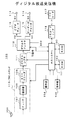
図1は、実施の形態としてのディジタル放送受信機100の構成を示している。
この受信機100は、全体の動作を制御するためのコントローラを構成するホストCPU101を有している。このCPU101には、CPU101の動作に必要なデータやプログラム等が格納されたROM(Read Only Memory)102と、CPU101の制御に伴って生成されるデータや後述するようにTSデータより取得されるセクションデータ等を格納したり、ワーキングエリアとして用いられるRAM(Random Access Memory)103と、複数の操作キー等が配された操作部104と、液晶表示素子等で構成され、受信機100の状態等を表示する表示部105とが接続されている。
【0027】
また、受信機100は、ディジタル放送信号を受信するためのアンテナ106と、このアンテナ106で受信される複数のRFチャネルのディジタル放送信号より所定のRFチャネルの放送信号を選択し、その所定のRFチャネルの放送信号に対応したディジタル変調データを出力するチューナ107とを有している。チューナ107における選局動作は、ユーザの操作部104の操作に基づき、CPU101によって制御される。
【0028】
また、受信機100は、チューナ107より出力されるディジタル変調データに対して復調処理をする復調器108と、この復調器108の出力データに対して誤り訂正処理をし、上述の所定のRFチャネルの放送信号に対応したMPEG2(Moving Picture Experts Group 2)TSデータを得るECC(Error Correction Code)デコーダ109とを有している。MPEG2TSデータは、MPEG2TSパケットが順次連続されてなるものである。ここで、チューナ107、復調器108およびECCデコーダ109で、フロントエンド110が構成されている。
【0029】
また、受信機100は、ECCデコーダ109より出力されるMPEG2TSデータを構成する、スクランブルされているビデオデータやオーディオデータのパケットに対してスクランブルの解除処理をするデスクランブラ111を有している。このデスクランブラ111からは、TS信号AまたはTS信号Bが出力される(図4参照)。TS信号Aは、上述のMPEG2TSパケットが順次連続されたMPEG2TSデータの他に、このTSデータと同期がとれているTSクロック信号、TSデータの有効区間を示すTSバリッド信号およびTSパケットの先頭バイトの位置を示すTSスタート信号を含んでいる。TS信号Bは、MPEG2TSデータの他に、このTSデータと同期がとれているTSクロック信号およびTSデータの有効区間を示すTSバリッド信号を含んでいる。
【0030】
また、受信機100は、デスクランブラ111より出力されるTS信号より、ユーザの操作部104の操作によって指定されたプログラム番号(チャネル)のビデオデータやオーディオデータのパケットを分離抽出し、それらのパケットより得られるビデオのPESパケットまたはESデータVDやオーディオのPESパケットまたはESデータADを出力すると共に、番組情報、限定受信情報等のセクションデータを含むパケットを分離抽出し、それらのパケットより得られるセクションデータSCDを出力するデマルチプレクサ112を有している。
【0031】
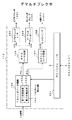
図2は、デマルチプレクサ112の構成を示している。このデマルチプレクサ112は、ホストCPU101とのインタフェースを行うホストCPUインタフェース回路151を有している。すなわち、デマルチプレクサ112はインタフェース回路151を介してCPU101に接続され、その動作はCPU101によって制御される。
【0032】
また、デマルチプレクサ112は、TSパケットのヘッダの分離解析をするTSヘッダパーサ回路152を有している。このパーサ回路152は、入力されるTS信号に含まれるTSデータを構成するTSパケットの先頭バイトを検出するTSスタート検出回路153を含んでいる。
【0033】
上述したようにデマルチプレクサ112に入力されるTS信号としては、2種類(TS信号A、TS信号B)がある(図4参照)。入力されるTS信号がTS信号Aである場合、パーサ回路152には、MPEG2TSデータの他に、TSクロック信号、TSバリッド信号およびTSスタート信号が入力される。一方、入力されるTS信号がTS信号Bである場合、パーサ回路152には、MPEG2TSデータの他に、TSクロック信号およびTSバリッド信号が入力される。このことから、パーサ回路152は、少なくとも、MPEG2TSデータ、TSクロック信号、TSバリッド信号およびTSスタート信号を入力するための端子を備えていることとなる。
【0034】
また、TSスタート検出回路153には、TSスタート信号を使用してTSパケットの先頭バイトを検出する第1の検出部153aおよびTSバリッド信号を使用してTSパケットの先頭バイトを検出する第2の検出部153bが設けられている。パーサ回路152にTS信号Aが入力される場合には、検出回路153で第1の検出部153aを使用することが選択され、一方、パーサ回路152にTS信号Bが入力される場合には、検出回路153で第2の検出部153bを使用することが選択される。この選択は、例えば、ホストCPU101より、インタフェース回路151を介して行われる。
【0035】
パーサ回路152は、TSスタート検出回路153で検出されたTSパケットの先頭バイトがMPEG規格通りの[0x47]であるか確認し、その後にインタフェース回路151を介してホストCPU101から設定された分離抽出すべきTSパケットのPID(パケット識別子)とパケットヘッダに含まれているPIDを比較し、分離抽出すべきTSパケットであるときは、そのパケットを分離抽出して出力する。ここで、分離抽出すべきTSパケットとしては、ビデオのPESパケットに係るTSパケット、オーディオのPESパケットに係るTSパケット、さらには番組情報、限定受信情報等を含んだセクションデータに係るTSパケットがある。
【0036】
また、デマルチプレクサ112は、TSヘッダパーサ回路152より出力されるビデオやオーディオのPESパケットに係るTSパケットPKv/aを入力し、PESパケットのパケットヘッダを解析し、ビデオのPESパケットまたはESデータと、オーディオのPESパケットまたはESデータとを、分離して出力するPESパーサ回路154を有している。
【0037】
また、デマルチプレクサ112は、パーサ回路154より出力されるビデオのPESパケットまたはESデータVDを、外部のビデオデコーダ113に出力するためのビデオデコーダインタフェース回路155と、パーサ回路154より出力されるオーディオのPESパケットまたはESデータADを、外部のオーディオデコーダ115に出力するためのオーディオデコーダインタフェース回路156とを有している。ここで、パーサ回路154よりESデータを出力する場合にあっては、パーサ回路154内でPESパケットよりパケットヘッダを除去してESデータを得るデコード処理も行われる。
【0038】
また、デマルチプレクサ112は、TSヘッダパーサ回路152より出力されるセクションデータに係るTSパケットPKsを入力し、インタフェース回路151を介してホストCPU101から設定されたフィルタリングのための設定値(テーブルID等)とセクションデータ値とを比較し、所望のセクションデータを分離抽出して出力するセクションパーサ回路157と、このセクションパーサ回路157より出力されるセクションデータSCDを、外部メモリ(RAM)103に出力するためのメモリインタフェース回路158とを有している。
【0039】
図2に示すデマルチプレクサ112の動作を、簡単に説明する。
TSヘッダパーサ回路152にTS信号が入力されると、TSスタート検出回路153では、TSデータを構成するTSパケットの先頭バイトが検出される。この場合、検出回路153では、使用することが選択された検出部で先頭バイトの検出が行われる。したがって、TS信号Aが入力される場合には、第1の検出部153aで、TSスタート信号が使用されてTSパケットの先頭バイトが検出される。一方、TS信号Bが入力される場合には、第2の検出部153bで、TSバリッド信号が使用されてTSパケットの先頭バイトが検出される。
【0040】
そして、パーサ回路152では、TSスタート検出回路153で検出されたTSパケットの先頭バイトがMPEG規格通りの[0x47]であるか確認され、その後にインタフェース回路151を介してホストCPUから設定された分離抽出すべきTSパケットのPID(パケット識別子)とパケットヘッダに含まれているPIDが比較され、分離抽出すべきTSパケットであるときは、そのパケットが分離抽出されて出力される。
【0041】
パーサ回路152で分離抽出されたビデオやオーディオのPESパケットに係るTSパケットPKv/aはPESパーサ回路154に供給される。このパーサ回路154では、PESパケットのパケットヘッダが解析され、ビデオのPESパケットまたはESデータと、オーディオのPESパケットまたはESデータとが分離されて出力される。
【0042】
そして、パーサ回路154より出力されるビデオのPESパケットまたはESデータVDは、インタフェース回路155を介して、デマルチプレクサ112の後段に配置された、ビデオデコーダ113に出力される。同様に、パーサ回路154より出力されるオーディオのPESパケットまたはESデータADは、インタフェース回路156を介して、デマルチプレクサ112の後段に配置された、オーディオデコーダ115に出力される。
【0043】
また、パーサ回路152で分離抽出されたセクションデータに係るTSパケットPKsは、セクションパーサ回路157に供給される。このパーサ回路157では、インタフェース回路151を介してホストCPU101から設定されたフィルタリングのための設定値(テーブルID等)とセクションデータ値とが比較され、所望のセクションデータが分離抽出される。そして、パーサ回路157で抽出されたセクションデータSCDは、インタフェース回路158を介して、外部メモリとしてのRAM103に出力される。
【0044】
また、図1に戻って、受信機100は、デマルチプレクサ112より出力されるビデオのPESパケットまたはESデータVDに対してデータ伸長処理等をしてビデオ信号SVを得るビデオデコーダ113と、そのビデオ信号SVを出力する出力端子114と、デマルチプレクサ112より出力されるオーディオのPESパケットまたはESデータADに対してデータ伸長処理等をしてオーディオ信号SAを得るオーディオデコーダ115と、そのオーディオ信号SAを出力する出力端子116とを有している。
【0045】
また、受信機100は、ICカード117が接続されるICカードインタフェース部118を有している。ICカードインタフェース部118は、CPU101に接続されている。ICカード117は、スクランブルの鍵情報を記憶していると共に、CPU101よりICカードインタフェース部118を介して送られてくる限定受信情報に基づき視聴の可/不可を判断し、可の場合にはスクランブルの鍵情報をICカードインタフェース部118を介してCPU101に送る機能を持っている。
【0046】
図1に示すディジタル放送受信機100の動作を説明する。
アンテナ106で受信された複数のRFチャネルのディジタル放送信号がチューナ107に供給され、所定のRFチャネルの放送信号が選択され、チューナ107からその放送信号に対応したディジタル変調データが出力される。そして、このディジタル変調データに対して復調器108で復調処理が行われ、この復調器108の出力データに対してECCデコーダ109で誤り訂正処理が行われてMPEG2TSデータが得られる。
【0047】
そして、このMPEG2TSデータがデスクランブラ111を介してデマルチプレクサ112に供給される。このデマルチプレクサ112では、ユーザの操作で指定されたプログラム番号(チャネル)のビデオデータやオーディオデータのTSパケットが分離され、それらのTSパケットより得られるビデオのPESパケットまたはESデータVDや、オーディオのPESパケットまたはESデータADが出力される。
【0048】
また、デマルチプレクサ112では、番組情報、限定受信情報等のセクションデータを含むTSパケットが分離抽出され、そのTSパケットより得られるセクションデータSCDが出力される。このセクションデータはCPU101を介してRAM103に格納される。CPU101は、このセクションデータに含まれる限定受信情報をICカードインタフェース部118を介してICカード117に供給する。
【0049】
ICカード117では、その限定受信情報に基づき視聴の可/不可が判断される。そして、可の場合には、ICカード117より、スクランブルの鍵情報がICカードインタフェース部118を介してCPU101に送られる。この鍵情報は、CPU101により、デスクランブラ111にセットされる。これにより、デスクランブラ111では、スクランブルされているビデオデータやオーディオデータのパケットのスクランブルが解除され、従ってデマルチプレクサ112より出力されるビデオのPESパケットまたはESデータVDや、オーディオのPESパケットまたはESデータADは、スクランブルが解除されたデータに係るものとなる。
【0050】
また、デマルチプレクサ112より出力されるビデオのPESパケットまたはESデータVDに対してビデオデコーダ113でデータ伸長等の処理が行われてビデオ信号SVが生成され、このビデオ信号SVが出力端子114に出力される。また、デマルチプレクサ112より出力されるオーディオのPESパケットまたはESデータADに対してオーディオデコーダ115でデータ伸長等の処理が行われてオーディオ信号SAが生成され、このオーディオ信号SAが出力端子116に出力される。
【0051】
以上説明したように、本実施の形態においては、デマルチプレクサ112のTSヘッダパーサ回路152のTSスタート検出回路153に、TSスタート信号を使用してTSパケットの先頭バイトを検出する第1の検出部153aおよびTSバリッド信号を使用してTSパケットの先頭バイトを検出する第2の検出部153bが設けられ、このTSスタート検出回路153ではデマルチプレクサ112の前段の回路であるデスクランブラ111より供給されるTS信号の種類(TS信号A、TS信号B)に応じた検出部が選択されて使用される。したがって、前段の回路であるデスクランブラ111よりTS信号Aが出力されるかTS信号Bが出力されるかによって使用の制約を受けることなく、同一構成のデマルチプレクサ112を使用することができる。
【0052】
なお、上述実施の形態においては、デマルチプレクサ112の前段の回路がデスクランブラ111であるものを示したが、デマルチプレクサ112の前段の回路がフロントエンド110であるものも考えられる。その場合にも、フロントエンド110がTS信号Aを出力するかTS信号Bを出力するかに依らず、同一構成のデマルチプレクサ112を使用することができる。
【0053】
また、上述実施の形態においては、デマルチプレクサ112をハードウェアで実現することを前提に説明したが(図2参照)、上述したデマルチプレクサ112の処理をソフトウエア処理で実現してもよいことは勿論である。
【0054】
【発明の効果】
この発明によれば、デマルチプレクサのTSパケットの先頭バイトを検出する検出手段に、TSスタート信号を使用してTSパケットの先頭バイトを検出する第1の検出部およびTSバリッド信号を使用してTSパケットの先頭バイトを検出する第2の検出部を設け、使用することが選択された検出部によってTSパケットの先頭バイトを検出する構成としたものであり、前段の回路による制約を受けることなく使用でき、設計の自由度が向上する。
【図面の簡単な説明】
【図1】実施の形態としてのディジタル放送受信機の構成を示すブロック図である。
【図2】ディジタル放送受信機に使用されているデマルチプレクサの構成を示すブロック図である。
【図3】ディジタル放送受信機に使用されている従来のデマルチプレクサの構成を示すブロック図である。
【図4】トランスポートストリーム信号(TS信号)の種類を説明するための図である。
【符号の説明】
100・・・ディジタル放送受信機、101・・・ホストCPU、106・・・アンテナ、107・・・チューナ、108・・・復調器、109・・・ECCデコーダ、110・・・フロントエンド、111・・・デスクランブラ、112・・・デマルチプレクサ、113・・・ビデオデコーダ、115・・・オーディオデコーダ、114,116・・・出力端子、117・・・ICカード、118・・・ICカードインタフェース部、151・・・ホストCPUインタフェース回路、152・・・TSヘッダパーサ回路、153・・・TSスタート検出回路、153a・・・第1の検出部、153b・・・第2の検出部、154・・・PESパーサ回路、155・・・ビデオデコーダインタフェース回路、156・・・オーディオデコーダインタフェース回路、157・・・セクションパーサ回路、158・・・メモリインタフェース回路[0001]
BACKGROUND OF THE INVENTION
The present invention relates to a demultiplexer suitable for use in, for example, a digital broadcast receiver and a receiver using the same. Specifically, the detection means for detecting the first byte of the transport stream packet includes a first detection unit for detecting the first byte of the transport stream packet using the transport stream start signal and the transport stream valid. By providing a second detection unit that detects the first byte of the transport stream packet using a signal and detecting the first byte of the transport stream packet by the detection unit selected to be used. The present invention relates to a demultiplexer that can be used without being restricted by the circuit in the previous stage.
[0002]
[Prior art]
FIG. 3 shows the configuration of a
[0003]
The
[0004]
The
[0005]
Here, there are two types of TS signals, TS signal A and TS signal B, as shown in FIG. The TS signal A includes TS data in which TS packets are sequentially continued, a transport stream clock signal (TS clock signal) synchronized with the TS data, and a transport stream valid signal (TS stream signal) indicating an effective section of the TS data ( TS valid signal) and a transport stream start signal (TS start signal) indicating the position of the first byte of the TS packet. The TS signal B includes TS data, a TS clock signal, and a TS valid signal.
[0006]
When the
[0007]
The
[0008]
Further, the
[0009]
The
[0010]
Further, the
[0011]
The operation of the
The received TS signal is input to the TS
[0012]
In the
[0013]
The
[0014]
The TS packet PKv / a related to the video or audio PES packet separated and extracted by the
[0015]
Then, the video PES packet or ES data VD output from the
[0016]
The TS packet PKs related to the section data separated and extracted by the
[0017]
[Problems to be solved by the invention]
As described above, the
[0018]
For example, when the preceding circuit outputs the TS signal B, the
[0019]
Therefore, an object of the present invention is to provide a demultiplexer or the like that can be used without being restricted by the preceding circuit.
[0020]
[Means for Solving the Problems]
The demultiplexer according to the present invention includes at least TS data in which TS packets are sequentially continued, a TS clock signal synchronized with the TS data, a TS valid signal indicating an effective section of the TS data, and a position of the first byte of the TS packet. Input means for inputting a TS start signal indicating When TS signal consisting of TS data, TS clock signal, TS valid signal and TS start signal is input, A first detector for detecting a first byte of a TS packet using a TS start signal; When TS signal consisting of TS data, TS clock signal and TS valid signal is input, A second detection unit for detecting the first byte of the TS packet using the TS valid signal is provided, and a detection unit for detecting the first byte of the TS packet by the detection unit selected to be used, Based on the selection means for selecting to use the first detection unit or the second detection unit and the detection result of the detection unit, the header of the TS packet is analyzed, and desired data is extracted from the TS data and output. Output means. For example, the TS packet is an MPEG2 TS packet.
[0021]
In addition, the receiver according to the present invention receives a broadcast signal and outputs a TS signal including TS data in which TS packets are sequentially continued, and desired data from the TS signal output from the receiver. And a demultiplexer for extracting and outputting. The demultiplexer indicates at least the TS data in which TS packets are sequentially continued, the TS clock signal synchronized with the TS data, the TS valid signal indicating the valid section of the TS data, and the position of the first byte of the TS packet. Input means for inputting a TS start signal; When TS signal consisting of TS data, TS clock signal, TS valid signal and TS start signal is input, A first detector for detecting a first byte of a TS packet using a TS start signal; When TS signal consisting of TS data, TS clock signal and TS valid signal is input, A second detection unit for detecting the first byte of the TS packet using the TS valid signal is provided, and a detection unit for detecting the first byte of the TS packet by the detection unit selected to be used, Based on the selection means for selecting to use the first detection unit or the second detection unit and the detection result of the detection unit, the header of the TS packet is analyzed, and desired data is extracted from the TS data and output. Output means.
[0022]
In the present invention, the TS signal output from the receiving unit is input to the demultiplexer. There are two types of TS signals, TS signal A and TS signal B. The TS signal A is composed of TS data, a TS clock signal, a TS valid signal, and a TS start signal, and the TS signal B is composed of TS data, a TS clock signal, and a TS valid signal.
[0023]
The detection means includes a first detection unit that detects the first byte of the TS packet using the TS start signal and a second detection unit that detects the first byte of the TS packet using the TS valid signal. Yes. When the TS signal A is input, the detection unit selects to use the first detection unit, and the detection unit uses the TS start signal to detect the first byte of the TS packet. On the other hand, when the TS signal B is input, the detection unit selects to use the second detection unit, and the detection unit uses the TS valid signal to detect the first byte of the TS packet.
[0024]
In the demultiplexer, the header of the TS packet is analyzed based on the detection result of the detection means, and desired data is separated and extracted from the TS data and output.
[0025]
As described above, the detection means of the demultiplexer includes the first detection unit that detects the first byte of the TS packet using the TS start signal and the second detection unit that detects the first byte of the TS packet using the TS valid signal. The first byte of the TS packet is detected by the detection unit selected to be used, and this demultiplexer can be used without being restricted by the previous circuit. .
[0026]
DETAILED DESCRIPTION OF THE INVENTION
Hereinafter, embodiments of the present invention will be described with reference to the drawings.
FIG. 1 shows a configuration of a
The
[0027]
The
[0028]
Further, the
[0029]
The
[0030]
The
[0031]
FIG. 2 shows the configuration of the
[0032]
Further, the
[0033]
As described above, there are two types of TS signals (TS signal A and TS signal B) input to the demultiplexer 112 (see FIG. 4). When the input TS signal is the TS signal A, the
[0034]
The TS start
[0035]
The
[0036]
Further, the
[0037]
The
[0038]
Further, the
[0039]
The operation of the
When a TS signal is input to the TS
[0040]
The
[0041]
The TS packet PKv / a related to the video or audio PES packet separated and extracted by the
[0042]
Then, the video PES packet or ES data VD output from the
[0043]
The TS packet PKs related to the section data separated and extracted by the
[0044]
Returning to FIG. 1, the
[0045]
The
[0046]
The operation of the
Digital broadcast signals of a plurality of RF channels received by the
[0047]
The MPEG2TS data is supplied to the
[0048]
The
[0049]
The IC card 117 determines whether viewing is possible or not based on the limited reception information. Then, if it is possible, the IC card 117 sends scramble key information to the
[0050]
Further, the video decoder 113 performs a process such as data decompression on the video PES packet or ES data VD output from the
[0051]
As described above, in the present embodiment, the first detection unit 153a that detects the first byte of the TS packet by using the TS start signal to the TS
[0052]
In the above-described embodiment, the circuit preceding the
[0053]
In the above-described embodiment, the
[0054]
【The invention's effect】
According to the present invention, the detection means for detecting the first byte of the TS packet of the demultiplexer uses the first detection unit that detects the first byte of the TS packet using the TS start signal and the TS valid signal as the TS valid signal. A second detection unit for detecting the first byte of the packet is provided, and the first byte of the TS packet is detected by the detection unit selected to be used, and is used without being restricted by the previous circuit. And the degree of freedom in design is improved.
[Brief description of the drawings]
FIG. 1 is a block diagram showing a configuration of a digital broadcast receiver as an embodiment.
FIG. 2 is a block diagram showing a configuration of a demultiplexer used in a digital broadcast receiver.
FIG. 3 is a block diagram showing a configuration of a conventional demultiplexer used in a digital broadcast receiver.
FIG. 4 is a diagram for explaining the types of transport stream signals (TS signals).
[Explanation of symbols]
DESCRIPTION OF
Claims (3)
上記トランスポートストリーム・データと上記トランスポートストリーム・クロック信号と上記トランスポートストリーム・バリッド信号と上記トランスポートストリーム・スタート信号とからなるトランスポートストリーム信号が入力される場合に、上記トランスポートストリーム・スタート信号を使用して上記トランスポートストリーム・パケットの先頭バイトを検出する第1の検出部および上記トランスポートストリーム・データと上記トランスポートストリーム・クロック信号と上記トランスポートストリーム・バリッド信号とからなるトランスポートストリーム信号が入力される場合に、トランスポートストリーム・バリッド信号を使用して上記トランスポートストリーム・パケットの先頭バイトを検出する第2の検出部が設けられ、使用することが選択された検出部によって上記トランスポートストリーム・パケットの先頭バイトを検出する検出手段と、
上記検出手段で上記第1の検出部または上記第2の検出部を使用するように選択する選択手段と、
上記検出手段により検出された先頭バイトが所定値であるかを確認した後で当該検出手段の検出結果に基づいて、上記トランスポートストリーム・パケットのヘッダを解析し、上記トランスポートストリーム・データより所望のデータを抽出して出力する出力手段と、
を備える、
デマルチプレクサ。Transport stream data in which at least transport stream packets are sequentially continued, a transport stream clock signal synchronized with the transport stream data, and a transport stream indicating a valid section of the transport stream data Input means for inputting a valid signal and a transport stream start signal indicating the position of the first byte of the transport stream packet;
When the transport stream signal composed of the transport stream data, the transport stream clock signal, the transport stream valid signal, and the transport stream start signal is input, the transport stream start A first detector for detecting the first byte of the transport stream packet using a signal, and a transport comprising the transport stream data, the transport stream clock signal, and the transport stream valid signal; When a stream signal is input, a second detection unit is provided that detects the first byte of the transport stream packet using the transport stream valid signal. A detecting means for detecting a first byte of the transport stream packet by the detection unit to be used is selected,
Selection means for selecting to use the first detection unit or the second detection unit in the detection unit;
After confirming whether the first byte detected by the detection means is a predetermined value, the header of the transport stream packet is analyzed based on the detection result of the detection means , and the desired value is obtained from the transport stream data. Output means for extracting and outputting the data of
Comprising
Demultiplexer.
請求項1に記載のデマルチプレクサ。The transport stream packet is an MPEG2 transport stream packet.
The demultiplexer according to claim 1.
上記受信部より出力される上記トランスポートストリーム信号より所望のデータを抽出して出力するデマルチプレクサと、
を備え、
上記デマルチプレクサは、
少なくともトランスポートストリーム・パケットが順次連続されたトランスポートストリーム・データ、該トランスポートストリーム・データと同期がとれているトランスポートストリーム・クロック信号、上記トランスポートストリーム・データの有効区間を示すトランスポートストリーム・バリッド信号および上記トランスポートストリーム・パケットの先頭バイトの位置を示すトランスポートストリーム・スタート信号を入力するための入力手段と、
上記トランスポートストリーム・データと上記トランスポートストリーム・クロック信号と上記トランスポートストリーム・バリッド信号と上記トランスポートストリーム・スタート信号からなるトランスポートストリーム信号が入力される場合に、上記トランスポートストリーム・スタート信号を使用して上記トランスポートストリーム・パケットの先頭バイトを検出する第1の検出部および上記トランスポートストリーム・データと上記トランスポートストリーム・クロック信号と上記トランスポートストリーム・バリッド信号からなるトランスポートストリーム信号が入力される場合に、トランスポートストリーム・バリッド信号を使用して上記トランスポートストリーム・パケットの先頭バイトを検出する第2の検出部が設けられ、使用することが選択された検出部によって上記トランスポートストリーム・パケットの先頭バイトを検出する検出手段と、
上記検出手段で上記第1の検出部または上記第2の検出部を使用するように選択する選択手段と、
上記検出手段により検出された先頭バイトが所定値であるかを確認した後で当該検出手段の検出結果に基づいて、上記トランスポートストリーム・パケットのヘッダを解析し、上記トランスポートストリーム・データより所望のデータを抽出して出力する出力手段と、
を有する、
受信機。A receiving unit that receives a broadcast signal and outputs a transport stream signal including transport stream data in which transport stream packets are sequentially continued;
A demultiplexer that extracts and outputs desired data from the transport stream signal output from the receiver;
With
The demultiplexer is
Transport stream data in which at least transport stream packets are sequentially continued, a transport stream clock signal synchronized with the transport stream data, and a transport stream indicating a valid section of the transport stream data Input means for inputting a valid signal and a transport stream start signal indicating the position of the first byte of the transport stream packet;
When the transport stream signal composed of the transport stream data, the transport stream clock signal, the transport stream valid signal, and the transport stream start signal is input, the transport stream start signal And a transport stream signal composed of the transport stream data, the transport stream clock signal, and the transport stream valid signal. Is provided, a second detector for detecting the first byte of the transport stream packet using a transport stream valid signal is provided, Detecting means for detecting the first byte of the transport stream packet by the detection unit it is selected to use,
Selection means for selecting to use the first detection unit or the second detection unit in the detection unit;
After confirming whether the first byte detected by the detection means is a predetermined value, the header of the transport stream packet is analyzed based on the detection result of the detection means , and the desired value is obtained from the transport stream data. Output means for extracting and outputting the data of
Having
Receiving machine.
Priority Applications (1)
| Application Number | Priority Date | Filing Date | Title |
|---|---|---|---|
| JP2000201402A JP4491925B2 (en) | 2000-07-03 | 2000-07-03 | Demultiplexer and receiver using the same |
Applications Claiming Priority (1)
| Application Number | Priority Date | Filing Date | Title |
|---|---|---|---|
| JP2000201402A JP4491925B2 (en) | 2000-07-03 | 2000-07-03 | Demultiplexer and receiver using the same |
Publications (2)
| Publication Number | Publication Date |
|---|---|
| JP2002026975A JP2002026975A (en) | 2002-01-25 |
| JP4491925B2 true JP4491925B2 (en) | 2010-06-30 |
Family
ID=18699102
Family Applications (1)
| Application Number | Title | Priority Date | Filing Date |
|---|---|---|---|
| JP2000201402A Expired - Fee Related JP4491925B2 (en) | 2000-07-03 | 2000-07-03 | Demultiplexer and receiver using the same |
Country Status (1)
| Country | Link |
|---|---|
| JP (1) | JP4491925B2 (en) |
Family Cites Families (7)
| Publication number | Priority date | Publication date | Assignee | Title |
|---|---|---|---|---|
| US5546399A (en) * | 1993-09-30 | 1996-08-13 | Kabushiki Kaisha Toshiba | Packet conversion apparatus and system |
| WO1997035393A1 (en) * | 1996-03-15 | 1997-09-25 | Hitachi, Ltd. | Data separating device |
| JP3490252B2 (en) * | 1997-05-16 | 2004-01-26 | 株式会社日立製作所 | Packet-multiplexed audio / video signal separation device |
| JPH11146354A (en) * | 1997-11-05 | 1999-05-28 | Toshiba Corp | Video / Audio decoding device |
| JPH11225315A (en) * | 1998-02-06 | 1999-08-17 | Fuji Xerox Co Ltd | Transmitter, receiver, transmission reception system, image forming device, image forming system, transmission method, reception method, transmission reception method and image forming method |
| JP3564309B2 (en) * | 1998-11-18 | 2004-09-08 | 松下電器産業株式会社 | Data processing device and control method thereof |
| JP2000183963A (en) * | 1998-12-14 | 2000-06-30 | Nec Corp | Transport stream switching circuit, multiplexing device and multiplexing method |
-
2000
- 2000-07-03 JP JP2000201402A patent/JP4491925B2/en not_active Expired - Fee Related
Also Published As
| Publication number | Publication date |
|---|---|
| JP2002026975A (en) | 2002-01-25 |
Similar Documents
| Publication | Publication Date | Title |
|---|---|---|
| US20050172314A1 (en) | Apparatus and method for data caching to reduce channel change delay | |
| JPH09162859A (en) | Scramble method and apparatus, descramble method and apparatus, and data transmission method and system | |
| KR100555658B1 (en) | Stream decode device | |
| KR20060060014A (en) | Pre-processing of descrambling data to reduce channel-change time | |
| JP2001069106A (en) | Stream demultiplexer | |
| JP2012005144A (en) | Adaptable transport protocol decoder | |
| JP2000013696A (en) | Digital broadcast receiver, channel selection method thereof, and data transmission method | |
| JPH11331721A (en) | Digital broadcast receiving terminal device | |
| CN100591092C (en) | Apparatus and method for outputting received broadcast signal | |
| US7349429B2 (en) | Method and apparatus for detecting format of closed caption data automatically and displaying the caption data | |
| JP4491925B2 (en) | Demultiplexer and receiver using the same | |
| US20070143862A1 (en) | Apparatuses and methods for copy protection | |
| JP4186514B2 (en) | Broadcast receiver | |
| JP3490252B2 (en) | Packet-multiplexed audio / video signal separation device | |
| US20070133541A1 (en) | Multiplexing and demultiplexing apparatus for delivering MPEG-2 TS packet error signal through cablecard interface and multiplexing and demultiplexing method using the same | |
| JP4293073B2 (en) | Television broadcast receiver | |
| KR100598360B1 (en) | Device and method for reducing video display delay time when switching channels | |
| EP1734751A2 (en) | Apparatuses, methods, and data structures for hard reset | |
| JP5455330B2 (en) | Image processing system, image processing method, and program | |
| JP2012070344A (en) | Digital broadcast reception device and digital broadcast reception method | |
| US20070136747A1 (en) | Broadcasting receiving apparatus and broadcasting receiving method | |
| JP4816008B2 (en) | Receiver | |
| JP4990658B2 (en) | Receiver | |
| JP2008147985A (en) | Digital broadcast receiving apparatus, digital broadcast system, control program, and readable recording medium | |
| JP4788279B2 (en) | Digital broadcast receiving apparatus and digital broadcast receiving method |
Legal Events
| Date | Code | Title | Description |
|---|---|---|---|
| RD04 | Notification of resignation of power of attorney |
Free format text: JAPANESE INTERMEDIATE CODE: A7424 Effective date: 20060517 |
|
| A621 | Written request for application examination |
Free format text: JAPANESE INTERMEDIATE CODE: A621 Effective date: 20070620 |
|
| A977 | Report on retrieval |
Free format text: JAPANESE INTERMEDIATE CODE: A971007 Effective date: 20090515 |
|
| A131 | Notification of reasons for refusal |
Free format text: JAPANESE INTERMEDIATE CODE: A131 Effective date: 20090526 |
|
| A521 | Request for written amendment filed |
Free format text: JAPANESE INTERMEDIATE CODE: A523 Effective date: 20090724 |
|
| RD03 | Notification of appointment of power of attorney |
Free format text: JAPANESE INTERMEDIATE CODE: A7423 Effective date: 20090916 |
|
| RD04 | Notification of resignation of power of attorney |
Free format text: JAPANESE INTERMEDIATE CODE: A7424 Effective date: 20091029 |
|
| A02 | Decision of refusal |
Free format text: JAPANESE INTERMEDIATE CODE: A02 Effective date: 20091117 |
|
| A521 | Request for written amendment filed |
Free format text: JAPANESE INTERMEDIATE CODE: A523 Effective date: 20100217 |
|
| A911 | Transfer to examiner for re-examination before appeal (zenchi) |
Free format text: JAPANESE INTERMEDIATE CODE: A911 Effective date: 20100224 |
|
| TRDD | Decision of grant or rejection written | ||
| A01 | Written decision to grant a patent or to grant a registration (utility model) |
Free format text: JAPANESE INTERMEDIATE CODE: A01 Effective date: 20100316 |
|
| A01 | Written decision to grant a patent or to grant a registration (utility model) |
Free format text: JAPANESE INTERMEDIATE CODE: A01 |
|
| A61 | First payment of annual fees (during grant procedure) |
Free format text: JAPANESE INTERMEDIATE CODE: A61 Effective date: 20100329 |
|
| FPAY | Renewal fee payment (event date is renewal date of database) |
Free format text: PAYMENT UNTIL: 20130416 Year of fee payment: 3 |
|
| LAPS | Cancellation because of no payment of annual fees |