JP4186514B2 - Broadcast receiver - Google Patents
Broadcast receiver Download PDFInfo
- Publication number
- JP4186514B2 JP4186514B2 JP2002154867A JP2002154867A JP4186514B2 JP 4186514 B2 JP4186514 B2 JP 4186514B2 JP 2002154867 A JP2002154867 A JP 2002154867A JP 2002154867 A JP2002154867 A JP 2002154867A JP 4186514 B2 JP4186514 B2 JP 4186514B2
- Authority
- JP
- Japan
- Prior art keywords
- signal
- audio
- signal processing
- video
- decoding
- Prior art date
- Legal status (The legal status is an assumption and is not a legal conclusion. Google has not performed a legal analysis and makes no representation as to the accuracy of the status listed.)
- Expired - Fee Related
Links
Images


Landscapes
- Television Systems (AREA)
- Compression Or Coding Systems Of Tv Signals (AREA)
- Television Receiver Circuits (AREA)
- Television Signal Processing For Recording (AREA)
Description
【0001】
【発明の属する技術分野】
テレビジョン放送を受信する放送受信機に関し、特に、デジタル信号を復号して出力する放送受信機に関する。
【0002】
【従来の技術】
BSデジタルテレビジョン放送などのデジタルテレビジョン放送が、多チャンネルや高画質が好評で、近年急速に普及しつつある。
【0003】
図4は、従来のデジタルテレビジョン放送を受信する放送受信機の構成図である。
放送受信機50は、放送を選局し受信するチューナ51と、スクランブルを解くデスクランブラ52と、TS(トランスポートストリーム)信号の多重化を解くデマルチプレクサ53と、圧縮符号化された映像信号を復号するビデオデコーダ54と、圧縮符号化された音声信号を復号するオーディオデコーダ55と、付加情報などを格納するメモリ56と、復号された映像信号の処理を行う信号処理装置57と、CPU58と、メモリ59と、デスクランブラ52でスクランブルを解くための情報が格納されたICカード60aとの情報の送受信を行うカードインターフェース60と、から構成される。
【0004】
さらに、デマルチプレクサ53は、TSのヘッダーのPID(Packet IDentification)を参照し、PES(Packetized Elementary Stream)またはセクションに振り分けるTSヘッダーパーサ53aと、映像信号及び音声信号またはメモリ59に格納する信号を振り分けるPESパーサ53bと、セクション信号をメモリ59に格納するセクションパーサ53cと、ビデオデコーダインターフェース53d、オーディオデコーダインターフェース53e、メモリインターフェース53fからなる。
【0005】
以下従来の放送受信機50の動作を説明する。
図示しないアンテナで受信されたRF(Radio Frequency)信号は、チューナ51に供給される。チューナ51では、選局、検波、復調された結果、TS信号が出力される。TS信号はデスクランブラ52に入力される。ここで、受信したデジタルテレビジョン放送が、有料放送などのようにスクランブルされていた場合、デスクランブラ52では、ICカード60aに格納された、暗号化を解く情報を元に、スクランブルを解く。スクランブルが解かれたTS信号はデマルチプレクサ53に入力される。ここで、TSヘッダーパーサ53aは、TSを構成するヘッダーに記載されているPIDを参照して、PESデータか、セクションデータかに分類し、PESの場合はPESパーサ53bに入力し、セクションの場合はセクションパーサ53cに入力する。PESパーサ53bは、PESのパケットを映像、音声または、メモリ56に格納してから実行するパケットかを判断し、それぞれ、ビデオデコーダインターフェース53d、オーディオデコーダインターフェース53e、メモリインターフェース53fに入力する。また、セクションの場合は、セクションパーサ53cによりセクションデータを取り込み、メモリインターフェース53fを介してメモリ56に入力する。デマルチプレクサ53で取り出された映像信号は、ビデオデコーダ54でデコードされ、音声信号は、オーディオデコーダ55でデコードされる。デコードされた映像信号は、さらに、信号処理装置57で映像信号の処理が行われる。例えば、図示しない表示デバイスの解像度にあわせるような解像度変換や、画素の補間などを行う。ここで、処理された映像信号は、図示しない表示デバイスに出力されて表示される。また、デコードされた音声信号は、スピーカなどの図示しない音声再生デバイスで出力される。
【0006】
上記のように、映像信号の場合、ビデオデコーダ54の後段に存在する信号処理装置57を介して図示しない表示デバイスに出力するため、デコードされた映像と音声の出力同期がずれるという問題があった。
【0007】
これを解決するため、従来では、オーディオデコーダ55でデコードの前にメモリやバッファなどの一時記憶領域を設け、映像信号の出力との同期を図るためデコードを遅延する機能を有するものがあった。
【0008】
【発明が解決しようとする課題】
しかし、従来の遅延の仕方は、デコード前に遅延させているため、内部の効果音などの他のPCM(Pulse Code Modulation)音声とのミキシングを行った後に遅延させることができないという問題があった。
【0009】
また、デコード前の遅延では、出力ポートが複数存在した場合に、同じ遅延時間でしか設定できないため、出力ポートごとに映像信号と音声信号の遅延時間を設定することができないという問題があった。
【0010】
また、システムによって異なる映像信号の遅延を自動的に検出して音声信号の出力遅延を設定することができないという問題があった。
本発明はこのような点に鑑みてなされたものであり、映像信号と音声信号とを正確に同期して出力することが可能な放送受信機を提供することを目的とする。
【0011】
【課題を解決するための手段】
本発明では上記課題を解決するために、テレビジョン放送を受信する放送受信機において、圧縮または符号化された映像信号を復号する映像復号手段と、圧縮または符号化された音声信号を復号する音声復号手段と、復号された前記映像信号の垂直ブランキングインターバルまたは水平ブランキングに時間情報を付加する時間情報付加手段と、前記時間情報が付加された前記映像信号について、表示デバイスに対応した信号処理を行う信号処理手段と、前記信号処理後の前記時間情報を検出し、前記信号処理前の前記時間情報と比較することによって、前記信号処理により経過した経過時間を算出する経過時間算出手段と、前記経過時間に応じて、復号された前記音声信号を一時蓄積する一時蓄積手段と、を有し、前記音声復号手段は複数の出力端子を有し、前記一時蓄積手段は、前記出力端子ごとの前記音声信号を、前記経過時間に応じて、別々に一時蓄積することを特徴とする放送受信機が提供される。
【0012】
上記構成によれば、映像復号手段で復号した映像信号の垂直ブランキングインターバルまたは水平ブランキングに付加された時間情報は、信号処理手段を介したのち、経過時間算出手段で検出され、信号処理手段での処理の経過時間が算出され、音声復号手段で復号された音声が出力端子ごとに、経過時間に応じて、別々に一時蓄積手段で一時蓄積されてから出力される。
【0013】
【発明の実施の形態】
以下本発明の実施の形態を図面を参照して説明する。
図1は本発明の実施の形態の放送受信機の原理構成図である。
【0014】
なお、図1では、放送を受信する部分などは省略している。
放送受信機1は、圧縮または符号化された映像信号を復号する映像復号手段2と、圧縮または符号化された音声信号を復号する音声復号手段3と、復号した映像信号を表示デバイスと対応するように、信号処理を行う信号処理手段4と、信号処理の前に復号した映像信号に時間情報を付加する時間情報付加手段5と、信号処理により経過した時間を算出する経過時間算出手段6と、復号された音声信号を一時蓄積する一時蓄積手段7と、を有する。
【0015】
映像復号手段2は信号処理手段4に復号した映像信号を入力するように接続され、信号処理手段4は、図示しない表示デバイスに映像信号を出力するように接続される。一方音声復号手段3は一時蓄積手段7に復号した音声信号を入力するように接続され、一時蓄積手段7は、図示しない音声出力デバイスに音声信号を出力するように接続される。また、時間情報付加手段5は、映像復号手段2により復号された映像信号が信号処理手段4に入力される前に、映像信号に時間情報の付加が可能なように配置される。経過時間算出手段6は、信号処理手段4で処理された映像信号から時間情報を検出可能なように配置され、さらに、時間情報付加手段5と接続され時間情報付加手段5からの信号を受信可能であり、一時蓄積手段7と接続され、信号を一時蓄積手段7に送信することが可能である。
【0016】
ここで、信号処理手段4は、図示しない表示デバイスの解像度と一致するような解像度変換や、解像度変換に伴う画素の補間などを行う。
以下放送受信機1の動作を説明する。
【0017】
圧縮または符号化された映像信号と音声信号が、それぞれ映像復号手段2、音声復号手段3に入力されると、復号が行われる。このとき映像信号と、音声信号の同期は図示しないタイミング信号により保たれている。映像復号手段2で、復号された映像信号は、信号処理手段4を介するため遅延が生じ、音声復号手段3より出力される音声信号との同期がとれなくなる。そこで、本発明の実施の形態の放送受信機1は、時間情報付加手段5により、映像復号手段2で出力された映像信号に時間情報を付加する。例えば、映像信号のVBI(垂直ブランキングインターバル)あるいはHBLK(水平ブランキング)などのブランキング期間に時間情報を付加する。信号処理手段4により映像信号の処理が行われた後、経過時間算出手段6により、付加された時間情報が映像信号より検出される。ここで、経過時間算出手段6は、時間情報付加手段5から映像信号に付加した時間情報を参照し、検出した時間情報と比較し、信号処理手段4での信号処理にかかった経過時間を算出する。算出された経過時間は、一時蓄積手段7に入力され、一時蓄積手段7では、入力された経過時間だけ、音声復号手段3で復号した音声信号を蓄積して図示しない音声出力デバイスに出力する。
【0018】
上記のように、信号処理手段4での信号処理の前に映像信号に時間情報を付加し、信号処理後に取り出し、信号処理にかかった時間を算出し、その時間だけ、音声復号手段3で復号した音声データを一時蓄積手段7に蓄積して出力を遅延させることで、出力する映像信号と音声信号を、正確に同期させることができる。
【0019】
以下、本発明の実施の形態の詳細を説明する。
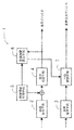
図2は、本発明の実施の形態の放送受信機のハードウェア構成図である。
放送受信機10は、放送を選局し受信するチューナ11と、スクランブルを解くデスクランブラ12と、TS信号の多重化を解くデマルチプレクサ13と、圧縮符号化された映像信号を復号するビデオデコーダ14と、圧縮符号化された音声信号を復号するオーディオデコーダ30と、オーディオデコーダ30に付随したメモリ30aと、付加情報などを格納するメモリ15と、復号された映像信号の処理を行う信号処理装置16と、タイムスタンプ設定装置17と、タイムスタンプ検出装置18と、CPU19と、メモリ20と、デスクランブラ12でスクランブルを解くための情報が格納されたICカード21aとの情報の送受信を行うカードインターフェース21と、から構成される。
【0020】
また、図2において、図1の映像復号手段2がビデオデコーダ14、音声復号手段3がオーディオデコーダ30、信号処理手段4が信号処理装置16、時間情報付加手段5がタイムスタンプ設定装置17、経過時間算出手段6がタイムスタンプ検出装置18、にそれぞれ対応している。なお、図1の一時蓄積手段7との対応部分については後述する。
【0021】
タイムスタンプ設定装置17は、ビデオデコーダ14と信号処理装置16の間で、デコードされた映像信号に時間情報(以下タイムスタンプという)を付加することが可能なように設置される。また、タイムスタンプ検出装置18は信号処理装置16で処理後の映像信号よりタイムスタンプを検出することが可能なように設置される。また、タイムスタンプ検出装置18は、タイムスタンプ設定装置17及びオーディオデコーダ30と接続されている。
【0022】
以下オーディオデコーダ30の詳細を以下説明する。
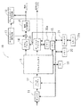
図3は、本発明の実施の形態のオーディオデコーダ構成図である。
ここでは、2つの出力ポートが存在する場合のオーディオデコーダ30の構成を示す。この2つの出力ポートは、例えば、テレビジョンのスピーカのための出力や、デジタルVTR(VideoTape Recorder)の出力のために用いられる。また、映像及び音声信号は、MPEG−2(Moving Picture Experts Group-2)形式で圧縮符号化されているとして説明する。
【0023】
オーディオデコーダ30は、図2では省略したPLL(位相同期回路)40より、TSパケットのPCR(Program Clock Reference)を参照して生成される、映像と音声を同期再生させるためのSTC(System Time Clock)を受信するタイマー31と、図示しないバッファやメモリ20とのインターフェースであるメモリインターフェース32と、入力がPES(Packetized Elementary Stream)の場合、時間管理情報であるPTS(Presentation Time Stamp)と、ES(Elementary Stream)を分離して取り出すPESデコーダ33と、タイマー31の時間と、PTSを比較して、映像との同期制御を行うAV同期制御部34と、MPEG−2形式の音声信号を復号するデコーダ35と、デコードした音声信号と混合するPCM(Pulse Code Modulation)形式の音声信号のサンプリング周波数を変換するサンプリング周波数変換部36と、デコードした音声信号と、外部からの音声信号を混合するPCM混合部37と、PCM形式の音声信号を出力時のバッファであるPCM出力バッファ38とを有する。さらに、メモリインターフェース32内に、遅延制御部32a、32bを有する。
【0024】
なお、図3において、遅延制御部32a、32bとメモリ30aは、図1の一時蓄積手段7と対応している。
遅延制御部32aは、デコーダ35の出力1側で、PCM混合部37とPCM出力バッファとの間に並列に接続されている。また、遅延制御部32bは、デコーダ35の出力2側で、PCM混合部37とPCM出力バッファとの間に並列に接続されている。また、遅延制御部32a、32bは、図2のタイムスタンプ検出装置18から遅延制御信号を受信し、信号処理装置16での処理遅延に対応した時間だけ、メモリ30aに音声信号を送信し、遅延時間の経過後にメモリ30aから音声信号を取り出し、PCM出力バッファ38に入力する機能を持つ。
【0025】
また、PESデコーダ33には、受信したPESやESのほか、あらかじめ図2で示したメモリ20などに記録されているAAC(Advanced Audio Coding)形式の音声信号などが入力される。
【0026】
以下、図2及び図3を用いて本発明の放送受信機10の動作を説明する。
図示しないアンテナで受信されたRF信号は、チューナ11に入力される。チューナ11では、選局、検波、復調された結果、TS信号が出力される。TS信号はデスクランブラ12に入力される。ここで、受信したデジタルテレビジョン放送が、有料放送などのようにスクランブルされていた場合、デスクランブラ12では、ICカード21aに格納された、暗号化を解く情報を元に、スクランブルを解く。スクランブルが解かれたTS信号はデマルチプレクサ13に入力される。デマルチプレクサ13では、TS信号から映像信号、音声信号、または番組情報などのセクションデータを分離する。デマルチプレクサ13でTSから分離された映像信号はビデオデコーダ14に入力されると、デコードが行われる。ビデオデコーダ14でデコードされた映像信号には、タイムスタンプ設定装置17によりタイムスタンプが、映像信号のVBIあるいはHBLKなどのブランキング期間に付加される。その後、図示しない表示デバイスの解像度にあわせた解像度変換や、それに伴う画素の補間などが信号処理装置16で行われる。信号処理装置16で処理が行われた映像信号は、図示しない表示デバイスに出力されるが、その前にタイムスタンプ検出装置18により、タイムスタンプ設定装置17で設定されたタイムスタンプがVBIやHBLKから抜き出され、信号処理装置16に入力される前のタイムスタンプと比較される。これにより、信号処理装置16での遅延時間が自動的に算出される。次にタイムスタンプ検出装置18で算出された遅延時間に関する情報が、遅延制御信号としてオーディオデコーダ30に出力される。
【0027】
オーディオデコーダ30は、遅延制御信号を遅延制御部32aまたは32bで受信すると、デコードされて、PCM混合部37で混合された音声信号を、PCM出力バッファ38にはすぐに出力せず、メモリ30aに蓄積する。つまり、遅延制御信号に含まれる信号処理装置16での遅延時間に対応した時間だけ、一時的に音声信号を保持する。ここで、遅延制御部32a、32bでは、メモリ30aに蓄積する時間を、別々に設定することができる。遅延時間に対応した時間が経過すると、遅延制御部32a、32bではメモリ30aに一時的に蓄積しておいた音声信号をPCM出力バッファ38に出力し、図示しない音声再生デバイスに出力する。
【0028】
このように、信号処理装置16での信号処理の前に映像信号に、タイムスタンプを付加し、信号処理後に取り出し、信号処理にかかった時間を算出し、その時間だけ、遅延制御部32aまたは32bの制御のもと、オーディオデコーダ30で復号した音声信号をメモリ30aに蓄積して出力を遅延させることで、出力する映像信号と音声信号を、正確に同期させることができる。
【0029】
また、上記の構成によれば、PCM混合部37で混合後の音声信号を、一時蓄積して遅延させて、映像信号と同期をとって再生することができる。
また、上記の構成によれば、オーディオデコーダ30に複数の出力ポートが存在した場合に、出力ポートごとに、遅延時間を設定することができる。
【0030】
なお、上記の説明では、遅延させるためのメモリ30aを独立に設けたが、メモリ20を用いても良いし、オーディオデコーダ30のバッファなどを一時蓄積領域として用いるようにしても良い。
【0031】
また、上記の説明では、オーディオデコーダ30は2つの出力ポートを持つとして説明したが、この数に限定されることはなく、1つでも、2以上でも良い。
【0032】
【発明の効果】
以上説明したように本発明では、復号された映像信号に時間情報を付加して、表示デバイスに対応した信号処理を行った後に、その時間情報を検出して信号処理の経過時間を自動的に算出し、経過時間に対応して、復号された音声信号を一時的に蓄積してから出力するようにしたので、映像信号と音声信号を正確に同期させて出力することが可能である。
【0033】
また、本発明によれば、PCM音声を混合後の音声信号を、一時蓄積して遅延させて、映像信号と同期をとって再生することができる。
また、本発明によれば、音声復号手段に複数の出力端子が存在した場合に、出力端子ごとに、遅延時間を設定することができる。
【図面の簡単な説明】
【図1】本発明の実施の形態の放送受信機の原理構成図である。
【図2】本発明の実施の形態の放送受信機のハードウェア構成図である。
【図3】本発明の実施の形態のオーディオデコーダ構成図である。
【図4】従来のデジタルテレビジョン放送を受信する放送受信機の構成図である。
【符号の説明】
1……放送受信機、2……映像復号手段、3……音声復号手段、4……信号処理手段、5……時間情報付加手段、6……経過時間算出手段、7……一時蓄積手段[0001]
BACKGROUND OF THE INVENTION
The present invention relates to a broadcast receiver that receives a television broadcast, and more particularly, to a broadcast receiver that decodes and outputs a digital signal.
[0002]
[Prior art]
Digital television broadcasts such as BS digital television broadcasts have gained popularity due to their multi-channel and high image quality, and have been rapidly spreading in recent years.
[0003]
FIG. 4 is a configuration diagram of a broadcast receiver that receives a conventional digital television broadcast.
The
[0004]
Further, the
[0005]
The operation of the
An RF (Radio Frequency) signal received by an antenna (not shown) is supplied to the
[0006]
As described above, in the case of a video signal, since it is output to a display device (not shown) via the
[0007]
In order to solve this problem, some
[0008]
[Problems to be solved by the invention]
However, since the conventional delay method is delayed before decoding, there is a problem that it cannot be delayed after mixing with another PCM (Pulse Code Modulation) sound such as an internal sound effect. .
[0009]
In addition, when there are a plurality of output ports, the delay before decoding has the problem that the delay time of the video signal and the audio signal cannot be set for each output port because it can be set only with the same delay time.
[0010]
In addition, there is a problem in that it is impossible to automatically detect the delay of the video signal that differs depending on the system and set the output delay of the audio signal.
The present invention has been made in view of such a point, and an object thereof is to provide a broadcast receiver capable of outputting a video signal and an audio signal in synchronization with each other accurately.
[0011]
[Means for Solving the Problems]
In the present invention, in order to solve the above-mentioned problem, in a broadcast receiver for receiving a television broadcast, video decoding means for decoding a compressed or encoded video signal and audio for decoding the compressed or encoded audio signal Decoding means, time information adding means for adding time information to a vertical blanking interval or horizontal blanking of the decoded video signal, and signal processing corresponding to a display device for the video signal to which the time information is added Signal processing means for performing, and by detecting the time information after the signal processing and comparing with the time information before the signal processing, an elapsed time calculating means for calculating an elapsed time by the signal processing, depending on the elapsed time, it has a, a temporary storage means for temporarily storing the audio signal decoded, the audio decoding means includes a plurality of Has a force terminal, the temporary storage means, said voice signal for each of the output terminals in response to the elapsed time, the broadcast receiver is provided, which comprises temporarily stored separately.
[0012]
According to the above configuration, the time information added to the vertical blanking interval or horizontal blanking of the video signal decoded by the video decoding means is detected by the elapsed time calculating means after passing through the signal processing means, and the signal processing means elapsed time of processing is calculated in, audio decoded by the audio decoding unit for each output terminal, depending on the elapsed time, and output after being temporarily stored in separate temporary storage means.
[0013]
DETAILED DESCRIPTION OF THE INVENTION
Embodiments of the present invention will be described below with reference to the drawings.
FIG. 1 is a principle configuration diagram of a broadcast receiver according to an embodiment of the present invention.
[0014]
In FIG. 1, a part for receiving a broadcast is omitted.
The
[0015]
The video decoding means 2 is connected to the signal processing means 4 so as to input the decoded video signal, and the signal processing means 4 is connected so as to output the video signal to a display device (not shown). On the other hand, the
[0016]
Here, the signal processing means 4 performs resolution conversion that matches the resolution of a display device (not shown), interpolation of pixels associated with the resolution conversion, and the like.
Hereinafter, the operation of the
[0017]
When the compressed or encoded video signal and audio signal are input to the
[0018]
As described above, time information is added to the video signal before the signal processing by the signal processing means 4, taken out after the signal processing, the time required for the signal processing is calculated, and only the time is decoded by the audio decoding means 3. By storing the audio data in the temporary storage means 7 and delaying the output, the output video signal and audio signal can be accurately synchronized.
[0019]
Details of the embodiment of the present invention will be described below.
FIG. 2 is a hardware configuration diagram of the broadcast receiver according to the embodiment of the present invention.
The
[0020]
2, the video decoding means 2 in FIG. 1 is a
[0021]
The time
[0022]
Details of the
FIG. 3 is an audio decoder configuration diagram according to the embodiment of the present invention.
Here, the configuration of the
[0023]
The
[0024]
In FIG. 3, the
The
[0025]
In addition to the received PES and ES, the
[0026]
Hereinafter, the operation of the
An RF signal received by an antenna (not shown) is input to the
[0027]
When the
[0028]
As described above, the time stamp is added to the video signal before the signal processing in the
[0029]
Moreover, according to said structure, the audio | voice signal after mixing by the
Further, according to the above configuration, when there are a plurality of output ports in the
[0030]
In the above description, the
[0031]
In the above description, the
[0032]
【The invention's effect】
As described above, in the present invention, time information is added to the decoded video signal, signal processing corresponding to the display device is performed, the time information is detected, and the elapsed time of signal processing is automatically determined. Since the calculated audio signal is temporarily stored and output in correspondence with the elapsed time, the video signal and the audio signal can be output in synchronization with each other.
[0033]
Further, according to the present invention, the audio signal after mixing the PCM audio can be temporarily accumulated and delayed and reproduced in synchronization with the video signal.
Further, according to the present invention, when there are a plurality of output terminals in the speech decoding means, a delay time can be set for each output terminal.
[Brief description of the drawings]
FIG. 1 is a principle configuration diagram of a broadcast receiver according to an embodiment of the present invention.
FIG. 2 is a hardware configuration diagram of a broadcast receiver according to the embodiment of this invention.
FIG. 3 is a configuration diagram of an audio decoder according to the embodiment of this invention.
FIG. 4 is a configuration diagram of a broadcast receiver that receives a conventional digital television broadcast.
[Explanation of symbols]
DESCRIPTION OF
Claims (2)
圧縮または符号化された映像信号を復号する映像復号手段と、
圧縮または符号化された音声信号を復号する音声復号手段と、
復号された前記映像信号の垂直ブランキングインターバルまたは水平ブランキングに時間情報を付加する時間情報付加手段と、
前記時間情報が付加された前記映像信号について、表示デバイスに対応した信号処理を行う信号処理手段と、
前記信号処理後の前記時間情報を検出し、前記信号処理前の前記時間情報と比較することによって、前記信号処理により経過した経過時間を算出する経過時間算出手段と、
前記経過時間に応じて、復号された前記音声信号を一時蓄積する一時蓄積手段と、
を有し、
前記音声復号手段は複数の出力端子を有し、前記一時蓄積手段は、前記出力端子ごとの前記音声信号を、前記経過時間に応じて、別々に一時蓄積することを特徴とする放送受信機。In a broadcast receiver that receives television broadcasts,
Video decoding means for decoding the compressed or encoded video signal;
Audio decoding means for decoding a compressed or encoded audio signal;
Time information adding means for adding time information to the vertical blanking interval or horizontal blanking of the decoded video signal;
Signal processing means for performing signal processing corresponding to a display device for the video signal to which the time information is added,
Elapsed time calculating means for detecting the time information after the signal processing and calculating the elapsed time by the signal processing by comparing with the time information before the signal processing;
Temporary storage means for temporarily storing the decoded audio signal according to the elapsed time;
I have a,
The broadcast receiver characterized in that the audio decoding means has a plurality of output terminals, and the temporary storage means temporarily stores the audio signals for each of the output terminals separately according to the elapsed time .
Priority Applications (1)
| Application Number | Priority Date | Filing Date | Title |
|---|---|---|---|
| JP2002154867A JP4186514B2 (en) | 2002-05-29 | 2002-05-29 | Broadcast receiver |
Applications Claiming Priority (1)
| Application Number | Priority Date | Filing Date | Title |
|---|---|---|---|
| JP2002154867A JP4186514B2 (en) | 2002-05-29 | 2002-05-29 | Broadcast receiver |
Publications (2)
| Publication Number | Publication Date |
|---|---|
| JP2003348489A JP2003348489A (en) | 2003-12-05 |
| JP4186514B2 true JP4186514B2 (en) | 2008-11-26 |
Family
ID=29771514
Family Applications (1)
| Application Number | Title | Priority Date | Filing Date |
|---|---|---|---|
| JP2002154867A Expired - Fee Related JP4186514B2 (en) | 2002-05-29 | 2002-05-29 | Broadcast receiver |
Country Status (1)
| Country | Link |
|---|---|
| JP (1) | JP4186514B2 (en) |
Families Citing this family (8)
| Publication number | Priority date | Publication date | Assignee | Title |
|---|---|---|---|---|
| JP4536653B2 (en) * | 2003-02-27 | 2010-09-01 | パナソニック株式会社 | Data processing apparatus and method |
| JP4660184B2 (en) * | 2004-12-27 | 2011-03-30 | 株式会社東芝 | Signal relay apparatus and signal relay method |
| JP4679372B2 (en) * | 2006-01-20 | 2011-04-27 | 株式会社日立製作所 | Image noise reduction processing apparatus and image display apparatus |
| JP2007312192A (en) * | 2006-05-19 | 2007-11-29 | Oki Electric Ind Co Ltd | Lip-sync evaluation apparatus and lip-sync adjustment apparatus |
| WO2009157078A1 (en) * | 2008-06-26 | 2009-12-30 | 富士通マイクロエレクトロニクス株式会社 | Video/audio data output device and video/audio data output method |
| JP5178375B2 (en) * | 2008-07-30 | 2013-04-10 | パナソニック株式会社 | Digital broadcast reproduction apparatus and digital broadcast reproduction method |
| JP2010062947A (en) * | 2008-09-04 | 2010-03-18 | Sony Corp | Audio-visual system and decoder |
| JP2011078136A (en) * | 2011-01-11 | 2011-04-14 | Hitachi Ltd | Video image noise reduction processing unit and video processing device |
-
2002
- 2002-05-29 JP JP2002154867A patent/JP4186514B2/en not_active Expired - Fee Related
Also Published As
| Publication number | Publication date |
|---|---|
| JP2003348489A (en) | 2003-12-05 |
Similar Documents
| Publication | Publication Date | Title |
|---|---|---|
| US6285408B1 (en) | Digital audio/video system and method integrates the operations of several digital devices into one simplified system | |
| KR100663049B1 (en) | Data processing device, its method and recording medium | |
| JP2006345169A (en) | Digital television receiving terminal device | |
| CN101483782B (en) | Digital broadcast receiver and digital broadcast receiving method | |
| US8331763B2 (en) | Apparatus and method for synchronizing reproduction time of time-shifted content with reproduction time of real-time content | |
| JP4186514B2 (en) | Broadcast receiver | |
| JP4257478B2 (en) | Recording / playback device | |
| US8224148B2 (en) | Decoding apparatus and decoding method | |
| JP5283914B2 (en) | Display control apparatus and display control method | |
| JP4366912B2 (en) | Decoding device and decoding method | |
| JP4723715B2 (en) | Multi-channel display data creation device and multi-channel display data creation method | |
| JP2001309255A (en) | Receiver of digital tv broadcasting | |
| JP2007096896A (en) | Broadcast recorder, broadcast recording and reproducing device and broadcast recording and reproduction program | |
| JP2002033712A (en) | Packet processor and packet output method therefor | |
| JP2007267420A (en) | Muting method for video signal | |
| JP2001044866A (en) | Information reception method and system thereof | |
| JP2005080142A (en) | Descrambling device | |
| WO2009119031A1 (en) | Digital television broadcast reception device | |
| JP2005012293A (en) | Decoding device | |
| JP4210997B2 (en) | Digital broadcast receiver | |
| KR100539731B1 (en) | Transport stream storage device and method | |
| JP2003209791A (en) | Device and method for recording and reproducing video signal | |
| JP2008252832A (en) | Receiver, data stream output apparatus, broadcasting system, control method of receiver, control method of data stream output apparatus, control program and recording medium | |
| JP2006148969A (en) | Muting method for video signal | |
| JP2004343516A (en) | Recording and playback processing apparatus |
Legal Events
| Date | Code | Title | Description |
|---|---|---|---|
| A621 | Written request for application examination |
Free format text: JAPANESE INTERMEDIATE CODE: A621 Effective date: 20050426 |
|
| A131 | Notification of reasons for refusal |
Free format text: JAPANESE INTERMEDIATE CODE: A131 Effective date: 20080603 |
|
| A521 | Written amendment |
Free format text: JAPANESE INTERMEDIATE CODE: A523 Effective date: 20080724 |
|
| TRDD | Decision of grant or rejection written | ||
| A01 | Written decision to grant a patent or to grant a registration (utility model) |
Free format text: JAPANESE INTERMEDIATE CODE: A01 Effective date: 20080819 |
|
| A01 | Written decision to grant a patent or to grant a registration (utility model) |
Free format text: JAPANESE INTERMEDIATE CODE: A01 |
|
| A61 | First payment of annual fees (during grant procedure) |
Free format text: JAPANESE INTERMEDIATE CODE: A61 Effective date: 20080901 |
|
| FPAY | Renewal fee payment (event date is renewal date of database) |
Free format text: PAYMENT UNTIL: 20110919 Year of fee payment: 3 |
|
| LAPS | Cancellation because of no payment of annual fees |