JP4491781B2 - Folding stand type display - Google Patents
Folding stand type display Download PDFInfo
- Publication number
- JP4491781B2 JP4491781B2 JP2004251120A JP2004251120A JP4491781B2 JP 4491781 B2 JP4491781 B2 JP 4491781B2 JP 2004251120 A JP2004251120 A JP 2004251120A JP 2004251120 A JP2004251120 A JP 2004251120A JP 4491781 B2 JP4491781 B2 JP 4491781B2
- Authority
- JP
- Japan
- Prior art keywords
- wall portion
- back wall
- folding
- front wall
- fold line
- Prior art date
- Legal status (The legal status is an assumption and is not a legal conclusion. Google has not performed a legal analysis and makes no representation as to the accuracy of the status listed.)
- Expired - Fee Related
Links
Images
Landscapes
- Display Racks (AREA)
Description
この発明は前壁部と背壁部との間を脹らませて自立出来るようにし且つ収納時や運搬時には折り畳んで小さくすることが出来るようにした、スタンド型表示体に関する。 The present invention relates to a stand-type display body that can be self-supported by being inflated between a front wall portion and a back wall portion, and can be folded and reduced during storage or transportation.
紙製の円筒などでは両側から均一に圧力が加えられると平面状に潰れることが知られている。この加圧方向とは直角の両側部方向からの圧力によって元の円筒に近い形状に復元させることが出来る。この原理を応用して、前記平面状のものの上下端部を外側に突出する円弧状に成形し、この円弧状の突出片をやはり円弧状の折り線を付けるようにして内側へ折り込むことによって、円筒に近い形状のものを形成することが出来る。 It is known that a paper cylinder or the like is flattened when pressure is applied uniformly from both sides. The pressure can be restored to a shape close to the original cylinder by pressure from both sides perpendicular to the pressing direction. By applying this principle, the upper and lower ends of the planar object are formed into an arc shape projecting outward, and the arc-shaped projecting piece is also folded inward with an arc-shaped folding line. A shape close to a cylinder can be formed.
このようにして形成される略円筒は、図面などの書類を丸めて入れる紙管などとして利用されている。 The substantially cylinder formed in this way is used as a paper tube or the like for rounding a document such as a drawing.
ところでこのような略円筒を立ててスタンド型表示体として利用しようと考えた時に問題となるのがその両端部の円弧部分であり、このままでは自立させることが出来ないため、この少なくとも下側と成る端部を略円筒に対して直角に切断したものとしなくてはならない。すると前記円弧状の突出片に代わって略円筒形状を保つものを端部にではなく中側に設ける必要がある。
さてこのようにして形成されるスタンド型表示体であるが、小は商品の宣伝用スタンドから大は等身大あるいはそれ以上の大型の広告塔などへの用途がある。しかしながら大型のものになればなるほど、運搬時や収納時に嵩張り取り扱いが容易でないと言う問題を生ずる。 Now, the stand-type display body formed in this way is used for a product such as a small advertisement stand from a product advertising stand to a large-sized advertising tower of a life size or more. However, the larger the size, the more difficult the bulk handling becomes during transportation and storage.
従ってこの発明では、運搬や収納が楽であり且つ組み立てや撤去が容易であるようなスタンド型表示体の提供を課題とする。 Accordingly, an object of the present invention is to provide a stand-type display body that is easy to transport and store and that can be easily assembled and removed.
上記課題は、各々の両側部で繋がる前壁部と背壁部と、前記前壁部または前記背壁部に設けられた前壁部と背壁部との間を脹らませるための折り込み部と、前記前壁部と前記背壁部とを平らに合わせた状態で折り畳み可能となるように前壁部と背壁部とに設けられた折り線とから成る折り畳み式のスタンド型表示体に於いて、背壁部側の前記折り線の左右の端部に、前記折り線から折り畳んだ際に前記折り線の部分に生ずる膨らみを逃がすための、前記両側部の各々の側に至る切り込み部が設けられていることを特徴とする、折り畳み式のスタンド型表示体とすることによって達成される。前壁部と背壁部とが両側部で繋がっていると言う場合、前壁部と背壁部とが別体でありそれ等が重合されて両側部で接着や蝶番止めが為されているもの、2つ折りによって前壁部と背壁部とが形成され両端部が接着されているもの、円筒を平らに潰して両側の折り目から前壁部と背壁部とが形成されているものなどを上げることが出来る。前壁部や背壁部の素材は任意であり、紙、合成樹脂板、金属板、木板等を必要に応じて選択したり混用することが可能である。また前記折り込み部、すなわち折り込み片は横向きだけでなく縦向きに形成することも可能である。The above-described problems include a front wall portion and a back wall portion that are connected to both sides, and a folding portion for inflating between the front wall portion or the back wall portion provided on the front wall portion or the back wall portion. When the front wall and the back wall section and foldable in a state where flat tailored to become like the front wall and the back wall portion formed Ru folding from the folding line and which is provided on the stand-type display of In this case , the left and right end portions of the fold line on the back wall portion side are cut to reach each side of the both side portions for releasing a bulge generated in the fold line portion when folded from the fold line. This is achieved by providing a foldable stand type display body characterized in that a portion is provided. When it says that the front wall part and the back wall part are connected on both sides, the front wall part and the back wall part are separate bodies, and they are superposed to be bonded and hinged on both sides The front wall and the back wall are formed by folding in two, and both ends are bonded, the cylinder is flattened and the front and back walls are formed from the folds on both sides, etc. Can be raised. The material of the front wall portion and the back wall portion is arbitrary, and paper, a synthetic resin plate, a metal plate, a wooden plate, or the like can be selected or mixed as necessary. The folded portion , that is, the folded piece can be formed not only horizontally but also vertically.
前記折り込み部を内側へ折り込むと折り込み片が形成されるが、この折り込み片が相対する側の壁部を押すため、前壁部と背壁部との間隔がこの折り込み片の分だけ開いて結果的に膨らみ立体化しこれにより全体が自立可能な状態と成る。
また膨らみが円に近くなるほど剛性が大きくなるため丈の高いものを提供することが出来る。前記折り込み部は前壁部または背壁部に折り込み片が形作られるようにその周囲に切り込みを設けて成るものであり、実質的に単なる切り込み片であるため、幾つ設けても重量が増加したり重心位置が変化するようなことが起こらず、追加部品を必要とせず、コストが安いと言う特長を有する。なお前記折り込み部の折り目と成る部位をミシン目として構成してもよい。When the folded portion is folded inward, a folded piece is formed, and since the folded piece presses the opposite wall portion, the distance between the front wall portion and the back wall portion is increased by the amount of the folded piece. It swells and becomes three-dimensional, and it becomes a state where the whole can become independent.
Moreover, since the rigidity becomes larger as the bulge becomes closer to a circle, it is possible to provide a product having a higher length. The folding portion is formed by providing notches around the front wall portion or the back wall portion so that the folding pieces are formed. Since the folding portion is substantially a mere notching piece, the number of the folding portions may increase the weight. The center of gravity position does not change, no additional parts are required, and the cost is low. In addition, you may comprise the site | part used as the fold of the said folding part as a perforation.
また前記内側へ折り込まれた折り込み部を元の状態に引き戻すことによって、前記前壁部と前記背壁部とを合わせた平らな状態にすることが出来る。更に前記折り線から折り返すことにより、全体をコンパクトに折り畳んで運搬したり収納したりすることが出来るように成る。この折り畳みの際に、前壁部と背壁部とが両側部で繋げられたものを折り返そうとすると、前記折り線の部分が膨らんで全く平らな状態に折り畳むことが出来にくく成ることがあるが、こうした場合でも背壁部側の前記折り線の左右の端部に前記両側部の各々の側に至る切り込み部を設けることによって、この膨らみを逃がすことが出来るのである。3つ折り以上に折り畳む場合にも有効である。Further, by pulling back the folded portion folded inward, the front wall portion and the back wall portion can be brought into a flat state. Furthermore, by folding back from the fold line, the whole can be folded compactly and transported or stored. When folding, if the front wall part and the back wall part are connected on both sides, the fold line part will swell and it will be difficult to fold it into a completely flat state. However, even in such a case, this bulge can be released by providing cut portions reaching the respective sides of the both side portions at the left and right ends of the folding line on the back wall side . This is also effective when folding in three or more folds.
以上この発明は、各々の両側部で繋がる前壁部と背壁部と、前記前壁部または前記背壁部に設けられた前壁部と背壁部との間を脹らませるための折り込み部と、前記前壁部と前記背壁部とを平らに合わせた状態で折り畳み可能となるように前壁部と背壁部とに設けられた折り線とから成る折り畳み式のスタンド型表示体に於いて、背壁部側の前記折り線の左右の端部に、前記折り線から折り畳んだ際に前記折り線の部分に生ずる膨らみを逃がすための、前記両側部の各々の側に至る切り込み部が設けられていることを特徴とする、折り畳み式のスタンド型表示体としたものである。前記折り線から折り返すことによって全体をコンパクトに折り畳むことが出来る。特に背壁部側の前記折り線の左右の端部に前記両側部の各々の側に至る切り込み部が設けられていることにより、前記折り線の部分に膨らみが生じた場合でもこれを逃がして平らな状態に折り畳むことが出来る効果がある。As described above, the present invention includes a front wall portion and a back wall portion that are connected to both sides, and a fold for inflating between the front wall portion and the front wall portion and the back wall portion provided on the back wall portion. parts and the front wall portion and the back wall section and the flat combined state collapsible so that it becomes formed Ru foldable stand display from the folding line provided on the front wall and the rear wall In the body, the left and right ends of the fold line on the back wall side reach the respective sides of the both sides for releasing the bulge generated in the fold line when folded from the fold line. A foldable stand-type display body is provided, which is provided with a cut portion. By folding back from the fold line, the whole can be folded compactly. In particular, the left and right end portions of the fold line on the back wall side are provided with cut portions that reach the respective sides of the fold line, so that even if the fold line portion bulges, this is escaped. There is an effect that can be folded flat.
この結果、運搬や収納が楽であり組み立てや撤去が容易であるようなスタンド型表示体を提供することに成功し、所期の目的を達成している。 As a result, the present invention has succeeded in providing a stand-type display body that is easy to transport and store and that can be easily assembled and removed, and achieves the intended purpose.
以下ではこの発明の一実施形態に付いて図面を参照しながら説明するが、この発明はこの実施形態にのみ限定されるものではない。Hereinafter, an embodiment of the present invention will be described with reference to the drawings, but the present invention is not limited to this embodiment .
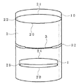
この実施形態のスタンド型表示体は、1枚の厚紙をその両側部で接着して筒状に成形すると共に、この接着部を一側としてこの筒状体を潰して前壁部1と背壁部2とを形成して成るものである。図中の符号10は前記前壁部1の頂部が背壁部2の頂部(実は後述する折り込み部20のラインである)よりも突出された冠部10を指す。また前壁部1と背壁部2とが潰れた平面状体の時に2つ折り可能と成るように中央部に折り線3が設けられている。この折り線3の左右の端部には、前記両側部の各々の側に至る切り込み部32,32が設けられている。更に背壁部2の中央部には、下側の折り込み部23と両側および上側の切り込み溝24とから構成される折り込み片25が設けられている。同様に前記背壁部2の頂部には折り込み部20が形成されている。The stand type display body of this embodiment is formed in a cylindrical shape by bonding one cardboard on both sides thereof, and the front wall portion 1 and the back wall are crushed by using this bonding portion as one side. It is formed by forming
前壁部1と背壁部2とが潰れた平面状体では、前記折り線3から2つ折りにすることが出来る。この状態から図1に示す立体構造に変化させるには、まず前記折り線3からの2つ折りを解いて細長い状態にして、次に前記折り込み片25を折り込み部23から内側に折り込むようにすると、折り込み片25の先端部が前壁部1の背面壁を押して前壁部1と背壁部2との間を膨らませるように作用する。同様に前記背壁部2の頂部が折り込み部20から内側に折り込まれることによって、折り込み片22の先端部の突き当て部21が前壁部1の背面壁を押して前壁部1と背壁部2との間を膨らませるように作用する。これによりこの実施形態のスタンド型表示体を自立させることが出来るのである。In the planar body in which the front wall portion 1 and the
またこの状態から折り畳むには先ほどと逆の手順で、まず前記折り込み片25を引き出して、前壁部1と背壁部2との間を潰し平面状体とし、前記折り線3から2つ折りにすればよい。この際に前記折り線3の左右の端部に前記両側部の各々の側に至る切り込み部32が設けられていることによって折り畳んだ時のテンションを逃がすことが出来るように成っている。すなわち前壁部1と背壁部2とが両側部分で繋げられたものを折り返そうとすると、前壁部1と背壁部2とが同一の大きさでその両側部で繋げられているため、前記折り線3の部分が膨らんで全く平らな状態に折り畳むことが出来にくく成る場合があるが、この問題を緩和するのがこの実施形態の折り線3及び左右の切り込み部32,32なのである。In order to fold from this state, the
このように2つ折りにして平らにすることが可能になっているので、単に前壁部1と背壁部2との間を潰しただけのものとは異なり運搬や収納が容易である。なおこの実施形態では前記折り込み部23の端部が前記両側部より内側に設けられている。これは内側へ折り込みやすくするための工夫であるが、この部位が前記折り込み部21のように両側部に至るように形成してもよいことは言うまでもない。 Thus, since it can be folded and flattened, it can be easily transported and stored, unlike the case in which the space between the front wall portion 1 and the
なおこの発明は上述の実施形態に限定されないから、例えば前記前壁部または前記背壁部にこの壁部が湾曲した時に壁部の一部を浮き出させるための切り込み部を設けることが可能である。また湾曲する壁部分に平板を貼り付けるなどしてこの平面を宣伝に利用することが可能である。 In addition, since this invention is not limited to the above-mentioned embodiment, when this wall part curves, for example, it is possible to provide the notch part for raising a part of wall part in the said front wall part or the said back wall part. . It is also possible to use this plane for advertising by sticking a flat plate to the curved wall portion.
1 前壁部
10 冠部
2 背壁部
20 折り込み部
21 突き当て部
22 折り込み片
23 折り込み部
24 切り込み溝
25 折り込み片
3 折り線
32 切り込み部DESCRIPTION OF SYMBOLS 1
Claims (1)
Priority Applications (1)
| Application Number | Priority Date | Filing Date | Title |
|---|---|---|---|
| JP2004251120A JP4491781B2 (en) | 2004-08-03 | 2004-08-03 | Folding stand type display |
Applications Claiming Priority (1)
| Application Number | Priority Date | Filing Date | Title |
|---|---|---|---|
| JP2004251120A JP4491781B2 (en) | 2004-08-03 | 2004-08-03 | Folding stand type display |
Related Parent Applications (1)
| Application Number | Title | Priority Date | Filing Date |
|---|---|---|---|
| JP2003185789A Division JP4362694B2 (en) | 2003-05-26 | 2003-05-26 | Folding stand type display |
Publications (3)
| Publication Number | Publication Date |
|---|---|
| JP2004355029A JP2004355029A (en) | 2004-12-16 |
| JP2004355029A5 JP2004355029A5 (en) | 2006-11-09 |
| JP4491781B2 true JP4491781B2 (en) | 2010-06-30 |
Family
ID=34056510
Family Applications (1)
| Application Number | Title | Priority Date | Filing Date |
|---|---|---|---|
| JP2004251120A Expired - Fee Related JP4491781B2 (en) | 2004-08-03 | 2004-08-03 | Folding stand type display |
Country Status (1)
| Country | Link |
|---|---|
| JP (1) | JP4491781B2 (en) |
Families Citing this family (1)
| Publication number | Priority date | Publication date | Assignee | Title |
|---|---|---|---|---|
| JP5141225B2 (en) * | 2007-12-10 | 2013-02-13 | 大日本印刷株式会社 | 3D advertisement |
Citations (2)
| Publication number | Priority date | Publication date | Assignee | Title |
|---|---|---|---|---|
| JPH0393422U (en) * | 1990-01-16 | 1991-09-24 | ||
| JP2002040940A (en) * | 2000-07-21 | 2002-02-08 | Tanakaya Inc | Bulging producer |
Family Cites Families (2)
| Publication number | Priority date | Publication date | Assignee | Title |
|---|---|---|---|---|
| JPS58195267U (en) * | 1982-06-22 | 1983-12-26 | 凸版印刷株式会社 | folding exhibit |
| JPH1195706A (en) * | 1997-09-25 | 1999-04-09 | Atlas Auto:Kk | Display plate |
-
2004
- 2004-08-03 JP JP2004251120A patent/JP4491781B2/en not_active Expired - Fee Related
Patent Citations (2)
| Publication number | Priority date | Publication date | Assignee | Title |
|---|---|---|---|---|
| JPH0393422U (en) * | 1990-01-16 | 1991-09-24 | ||
| JP2002040940A (en) * | 2000-07-21 | 2002-02-08 | Tanakaya Inc | Bulging producer |
Also Published As
| Publication number | Publication date |
|---|---|
| JP2004355029A (en) | 2004-12-16 |
Similar Documents
| Publication | Publication Date | Title |
|---|---|---|
| JP4491781B2 (en) | Folding stand type display | |
| JP6794676B2 (en) | Self-supporting packaging | |
| JP4362694B2 (en) | Folding stand type display | |
| US20090207112A1 (en) | Viewing device and book-type arrangement of a plurality of interconnected viewing devices | |
| JP6802026B2 (en) | Bag-in-box | |
| JP3223144U (en) | Folding container | |
| JP2012091841A (en) | Packaging box | |
| JP3129591U (en) | A self-supporting box-type stand-type advertising medium | |
| JP3137624U (en) | Printed matter | |
| JP4054628B2 (en) | Packaging box | |
| JP2006232402A (en) | Packaging | |
| JP6641743B2 (en) | Portable toilet for vehicles | |
| JP2004359277A (en) | Wrapping body | |
| JP6361325B2 (en) | Exhibit | |
| JP4430965B2 (en) | Collection container with fluorescent lamp waste collection tool | |
| JP3132384U (en) | Box-type display device | |
| JP2012140152A (en) | Collapsible enclosure member | |
| WO2022180769A1 (en) | Core material for commercial sample and commercial sample | |
| JP3151129U (en) | Containment bag | |
| JP2004354955A (en) | Stand type display material | |
| JP2009039343A (en) | Merchandise display stand | |
| JP2010095281A (en) | Roll receiver | |
| JP3140382U (en) | Folding cardboard boxes | |
| JP2005131058A (en) | Assembled file stand | |
| JP2001225874A (en) | Corrugated board cushion |
Legal Events
| Date | Code | Title | Description |
|---|---|---|---|
| A521 | Written amendment |
Free format text: JAPANESE INTERMEDIATE CODE: A523 Effective date: 20060523 |
|
| A621 | Written request for application examination |
Free format text: JAPANESE INTERMEDIATE CODE: A621 Effective date: 20060523 |
|
| A521 | Written amendment |
Free format text: JAPANESE INTERMEDIATE CODE: A523 Effective date: 20060801 |
|
| A131 | Notification of reasons for refusal |
Free format text: JAPANESE INTERMEDIATE CODE: A131 Effective date: 20090623 |
|
| A521 | Written amendment |
Free format text: JAPANESE INTERMEDIATE CODE: A523 Effective date: 20090820 |
|
| A02 | Decision of refusal |
Free format text: JAPANESE INTERMEDIATE CODE: A02 Effective date: 20091027 |
|
| A521 | Written amendment |
Free format text: JAPANESE INTERMEDIATE CODE: A523 Effective date: 20091225 |
|
| A911 | Transfer of reconsideration by examiner before appeal (zenchi) |
Free format text: JAPANESE INTERMEDIATE CODE: A911 Effective date: 20100217 |
|
| TRDD | Decision of grant or rejection written | ||
| A01 | Written decision to grant a patent or to grant a registration (utility model) |
Free format text: JAPANESE INTERMEDIATE CODE: A01 Effective date: 20100316 |
|
| A01 | Written decision to grant a patent or to grant a registration (utility model) |
Free format text: JAPANESE INTERMEDIATE CODE: A01 |
|
| A61 | First payment of annual fees (during grant procedure) |
Free format text: JAPANESE INTERMEDIATE CODE: A61 Effective date: 20100325 |
|
| R150 | Certificate of patent or registration of utility model |
Ref document number: 4491781 Country of ref document: JP Free format text: JAPANESE INTERMEDIATE CODE: R150 Free format text: JAPANESE INTERMEDIATE CODE: R150 |
|
| FPAY | Renewal fee payment (event date is renewal date of database) |
Free format text: PAYMENT UNTIL: 20130416 Year of fee payment: 3 |
|
| R250 | Receipt of annual fees |
Free format text: JAPANESE INTERMEDIATE CODE: R250 |
|
| R250 | Receipt of annual fees |
Free format text: JAPANESE INTERMEDIATE CODE: R250 |
|
| R250 | Receipt of annual fees |
Free format text: JAPANESE INTERMEDIATE CODE: R250 |
|
| R250 | Receipt of annual fees |
Free format text: JAPANESE INTERMEDIATE CODE: R250 |
|
| R250 | Receipt of annual fees |
Free format text: JAPANESE INTERMEDIATE CODE: R250 |
|
| LAPS | Cancellation because of no payment of annual fees |