JP4490303B2 - Biological light measurement device - Google Patents
Biological light measurement device Download PDFInfo
- Publication number
- JP4490303B2 JP4490303B2 JP2005036372A JP2005036372A JP4490303B2 JP 4490303 B2 JP4490303 B2 JP 4490303B2 JP 2005036372 A JP2005036372 A JP 2005036372A JP 2005036372 A JP2005036372 A JP 2005036372A JP 4490303 B2 JP4490303 B2 JP 4490303B2
- Authority
- JP
- Japan
- Prior art keywords
- light
- measurement
- probe
- subject
- control unit
- Prior art date
- Legal status (The legal status is an assumption and is not a legal conclusion. Google has not performed a legal analysis and makes no representation as to the accuracy of the status listed.)
- Expired - Fee Related
Links
Images


Description
この発明は、光を用いて生体内部情報を計測する生体光計測装置に関するものである。 The present invention relates to a biological light measuring device that measures internal biological information using light.
一般に、生体光計測装置では、被検体の頭皮上に入射させた近赤外光が約3cm離れた位置で検出される。そして、この検出光の強度に基づいて、頭表から20mmより浅い大脳表面を含む複数部位の血液量の変化が、2次元的な濃淡画像(トポグラフ)として表示画面に表示される。 In general, in a biological light measurement apparatus, near infrared light incident on the scalp of a subject is detected at a position about 3 cm away. Based on the intensity of the detected light, changes in blood volume at a plurality of sites including the cerebral surface shallower than 20 mm from the head surface are displayed on the display screen as a two-dimensional grayscale image (topograph).
このような生体光計測装置においては、脳の機能的局在性の考えに基づく診断装置としての実用価値を向上させるため、計測結果を示す濃淡画像が脳表面の構造(脳回gyrusや脳溝sulcus)とどのような位置関係にあるのかを示すことが求められている。これに対して、従来、MRIやX線CT装置により得た脳の3次元(3D)像の上に、生体光計測装置による濃淡画像を表示する機能を持つ生体光計測装置が提案されている(例えば、特許文献1参照)。 In such a biological optical measuring device, in order to improve the practical value as a diagnostic device based on the idea of the functional localization of the brain, the gray image showing the measurement result is the structure of the brain surface (cerebral gyrus and sulcus) It is required to indicate the positional relationship with (sulcus). On the other hand, a biological light measurement device having a function of displaying a grayscale image by a biological light measurement device on a three-dimensional (3D) image of a brain obtained by an MRI or X-ray CT device has been proposed. (For example, refer to Patent Document 1).
しかし、上記のような従来の生体光計測装置は、計測結果と脳表面の構造との位置関係を示すために、別のモダリティのデータを使用する必要があり、多くの手間がかかってしまう。即ち、従来の生体光計測装置自体には、計測部位と脳表面の構造との位置関係を測定する機能はなかった。また、簡便な方法として、頭の外観図の上にプローブホルダの取付位置を重ねて表示した図(いわゆる「ボディマーク」)を、表示データに添えて表示することも行われているが、あくまで目安に過ぎず、脳表面の構造との位置関係を正確に表示するものではなかった。 However, the conventional living body light measuring apparatus as described above needs to use data of another modality in order to indicate the positional relationship between the measurement result and the structure of the brain surface, which takes much time and effort. That is, the conventional biological light measurement device itself has no function of measuring the positional relationship between the measurement site and the structure of the brain surface. In addition, as a simple method, a figure (so-called “body mark”) in which the probe holder mounting position is superimposed on the external view of the head is displayed along with the display data. It is only a guide and does not accurately display the positional relationship with the structure of the brain surface.
この発明は、上記のような課題を解決するためになされたものであり、被検体における計測部位の位置をより正確に測定することができる生体光計測装置を得ることを目的とする。 The present invention has been made to solve the above-described problems, and an object of the present invention is to obtain a biological light measurement device that can more accurately measure the position of a measurement site in a subject.
この発明に係る生体光計測装置は、被検体に光を照射する複数の光照射プローブと、被検体から戻る光を検出する複数の光検出プローブとを有し、被検体に装着される装着部、光検出プローブでの検出光量を計測する制御部、及び制御部による計測結果を表示する表示部を備え、制御部は、装着部上で間隔が既知の第1及び第2の点間で被検体に対して光を照射・検出したときの検出光量と、被検体上の特徴点と第1の点との間で被検体に対して光を照射・検出したときの検出光量との変化から、第1の点と特徴点との間の距離を測定し、特徴点に対する計測部位の位置を表示部に表示させる。
また、この発明に係る生体光計測装置は、プローブホルダと、プローブホルダに取り付けられ被検体に光を照射する複数の光照射プローブと、プローブホルダに取り付けられ被検体から戻る光を検出する複数の光検出プローブとを有し、被検体に装着される装着部、光検出プローブでの検出光量を計測する制御部、及び制御部による計測結果を表示する表示部を備え、プローブホルダには、目盛が付されており、制御部は、被検体上の特徴点に対応する目盛の値を入力することにより、特徴点に対する計測部位の位置を表示部に表示させる。
A biological light measurement apparatus according to the present invention includes a plurality of light irradiation probes that irradiate light to a subject and a plurality of light detection probes that detect light returning from the subject, and a mounting portion that is attached to the subject A control unit that measures the amount of light detected by the light detection probe, and a display unit that displays a measurement result by the control unit, and the control unit covers between the first and second points having a known interval on the mounting unit. From the change in the amount of light detected when the sample is irradiated / detected and the amount of light detected when the sample is irradiated / detected between the feature point on the subject and the first point The distance between the first point and the feature point is measured, and the position of the measurement site with respect to the feature point is displayed on the display unit.
The biological light measurement apparatus according to the present invention includes a probe holder, a plurality of light irradiation probes attached to the probe holder for irradiating light to the subject, and a plurality of light attached to the probe holder for detecting light returning from the subject. The probe holder includes a mounting unit that is mounted on the subject, a control unit that measures the amount of light detected by the light detection probe, and a display unit that displays a measurement result by the control unit. The control unit causes the display unit to display the position of the measurement site with respect to the feature point by inputting a scale value corresponding to the feature point on the subject.
この発明の生体光計測装置は、装着部上で間隔が既知の第1及び第2の点間で被検体に対して光を照射・検出したときの検出光量と、被検体上の特徴点と第1の点との間で被検体に対して光を照射・検出したときの検出光量との変化から、第1の点と特徴点との間の距離を測定し、特徴点に対する計測部位の位置を表示部に表示させる制御部を用いたので、被検体における計測部位の位置をより正確に測定することができる。
また、プローブホルダに目盛を付し、被検体上の特徴点に対応する目盛の値を制御部に入力することにより、特徴点に対する計測部位の位置を表示部に表示させるようにしたので、被検体における計測部位の位置をより正確に測定することができる。
The biological light measurement apparatus according to the present invention includes a detected light amount when the subject is irradiated with light between the first and second points having a known interval on the mounting portion, and a feature point on the subject. The distance between the first point and the feature point is measured from the change in the detected light amount when the subject is irradiated with light and detected between the first point and the measurement site of the feature point. Since the control unit that displays the position on the display unit is used, the position of the measurement site in the subject can be measured more accurately.
In addition, since the scale is attached to the probe holder and the scale value corresponding to the feature point on the subject is input to the control unit, the position of the measurement site with respect to the feature point is displayed on the display unit. The position of the measurement site in the sample can be measured more accurately.
以下、この発明を実施するための最良の形態について、図面を参照して説明する。
実施の形態1。
図1はこの発明の実施の形態1による生体光計測装置の要部を示す斜視図である。生体光計測装置は、計測装置本体と、被検体に装着される装着部7と、計測装置本体と装着部7との間に接続された光ファイバ群8とを有している。
The best mode for carrying out the present invention will be described below with reference to the drawings.
1 is a perspective view showing a main part of a biological light measurement device according to
装着部7は、プローブホルダ1と、プローブホルダ1に取り付けられた複数の光照射プローブ2及び複数の光検出プローブ3と、プローブホルダ1を被検体の頭部に固定するための複数のベルト4とを有している。図1では、光照射プローブ2を白で、光検出プローブ3を黒で示している。プローブホルダ1は、頭部の表面形状に合わせた曲面形状を有している。
The
光ファイバ群8は、光照射プローブ2に接続された複数本の照射用光ファイバ5と、光検出プローブ3に接続された複数本の検出用光ファイバ6とを有している。
The
図2は図1のプローブ2,3のプローブホルダ1への平面的な配置状態を示す説明図である。この例では、光照射プローブ2は、第1〜第5の光照射プローブ2a〜2eを含んでいる。また、光検出プローブ3は、第1〜第4の光検出プローブ3a〜3dを含んでいる。光照射プローブ2a〜2e及び光検出プローブ3a〜3dは、予め定められた間隔をおいてマトリクス状に配置されている。また、光照射プローブ2a〜2eと光検出プローブ3a〜3dとは、交互に配置されている。
FIG. 2 is an explanatory view showing a planar arrangement of the
この例では、プローブ2,3の12対の組み合わせについて、12チャンネルのロックインアンプで光透過量を計測する。12対の組み合わせとは、プローブ2a,3a、プローブ2a,3b、プローブ2b,3a、プローブ2b,3c、プローブ2c,3a、プローブ2c,3b、プローブ2c,3c、プローブ2c,3d、プローブ2d,3b、プローブ2d,3d、プローブ2e,3c、及びプローブ2e,3dである。また、複数の波長を使用するときには波長毎に光透過量を計測するので、2波長であれば合計24チャンネルが用いられる。
In this example, the light transmission amount is measured with a 12-channel lock-in amplifier for 12 pairs of
図3は図1の生体光計測装置の計測装置本体を示すブロック図である。計測装置本体11は、光源部12、受光部13、制御部14及び表示部15を有している。光源部12は、光照射プローブ2に送る光を発生する。受光部13は、光検出プローブ3から送られた光を受光し電気信号に変換する。制御部14は、光源部12、受光部13及び表示部15を制御する。また、制御部14は、受光部13からの信号に基づいて生体内部情報を計測し計測結果を表示部15に表示させる。
FIG. 3 is a block diagram showing a measurement device main body of the biological light measurement device of FIG. The
制御部14は、コンピュータにより構成されている。制御部14の動作モードには、被検体の頭部における計測部位の位置を測定するための位置測定モードと、生体内部情報を計測するための通常計測モードとが含まれている。
The
次に、頭部における計測部位の位置を測定する方法について説明する。
生体光計測装置では、プローブ2,3の位置が固定されており、光照射プローブ2と光検出プローブ3との間の距離は一定である。このため、透過光量の変化は、主にプローブ2,3間の透光媒体物質の光吸収率の変化に依存する。即ち、検出される光の強度は照射される近赤外光を主に吸収する血色素(ヘモグロビン)濃度変化に依存する。従って、通常の計測では、プローブ2,3の位置を固定し、局所血液量の変化を求めている。
Next, a method for measuring the position of the measurement site on the head will be described.
In the biological light measurement device, the positions of the
これに対し、位置測定では、生体内部情報の計測とは逆に、光が透過する媒体物質の光吸収率を一定とみなし、プローブ2,3間の距離を変えたときの透過光量変化から、頭部表面の特徴点からのプローブ2,3の位置を求める。
On the other hand, in the position measurement, on the contrary to the measurement of in-vivo internal information, the light absorption rate of the medium substance through which light is transmitted is considered to be constant, and the transmitted light amount change when the distance between the
図4は媒体物質の光吸収率を一定としたときの図1のプローブ2,3間の距離と光透過量との関係を示すグラフである。図4に示すように、距離xが大きくなると、光透過量(検出光量)は減少する。プローブ2,3間の標準の間隔をx0(例えば30mm)とし、距離xが変化したときの光量の変化ΔF=F(x)−F(x0)を計測すれば、距離xの変化量Δxを知ることができる。即ち、既知の微分値(dF/dx)を用いて、Δx=ΔF/(dF/dx)(一次近似値)に近い値になる。
FIG. 4 is a graph showing the relationship between the distance between the
F(x)は計測の条件によってさまざまに変化するが、(dF/dx)は光の通る媒体(生体組織)の性質に依存し、被検体間でほぼ共通であるので、予め計測した(dF/dx)のデータを用いることにより、1次近似値が得られる。 F (x) varies depending on the measurement conditions, but (dF / dx) depends on the property of the medium (biological tissue) through which light passes and is almost common between subjects. / Dx) data is used to obtain a first order approximation.
このように、Δxが求められることから、1個の光照射プローブ2を可動とし、光照射プローブ2の移動に伴う2個(3個以上でもよい)の光検出プローブ3での検出光量変化を求めれば、移動後の光照射プローブ2の位置と2個の光検出プローブ3との間の距離が求められる。そして、移動後の光照射プローブ2の位置として頭部表面の特徴点を選択すれば、その特徴点と光検出プローブ3との位置関係を把握することができる。
Since Δx is thus obtained, one
特徴点としては、脳の構造との関連に代わるものとして、頭皮上の特徴部位、例えば眼(眼窩)、耳孔、正中線やOMライン上の点を選択することができる。また、頭骨計測に使われる各種の計測点又は線(nasion:鼻根点、inion:外後頭隆起点、bregma:冠状縫合矢状縫合交点)等を特徴点として選択することもできる。 As a feature point, a feature part on the scalp, for example, a point on the eye (orbit), ear canal, midline or OM line can be selected as an alternative to the relation with the structure of the brain. In addition, various measurement points or lines (nasion: nose root point, inion: external occipital ridge point, bregma: coronary suture sagittal intersection) used for skull measurement can be selected as feature points.
図5は図1の生体光計測装置による位置測定方法を示す説明図である。位置測定を行う場合、装着部7を被検体の頭部に装着した後、制御部14の動作モードを位置測定モードに切り換える。そして、まず、初期検出光量の測定を行う。即ち、例えば第1の光照射プローブ2aから光を照射させ、第1及び第2の光検出プローブ3a,3bによる検出光量を制御部14により測定させる。上述したように、初期検出光量は、その都度測定せず、常に同じ値を近似値として用いてもよい。
FIG. 5 is an explanatory view showing a position measuring method by the biological light measuring device of FIG. When performing position measurement, after mounting the mounting
次に、第1の光照射プローブ2aを第1の特徴点P1に移動させる。そして、移動後検出光量の測定を行う。即ち、特徴点P1において、第1の光照射プローブ2aから光を照射させ、第1及び第2の光検出プローブ3a,3bによる検出光量を制御部14により測定させる。ここで、検出光量の絶対値を確保するため、特徴点にできるだけ近いプローブ2,3の組み合わせを選択して測定するのが好適である。勿論、初期位置と特徴点P1とにおける第1の光照射プローブ2aからの照射光の照射条件(強度等)は同じである。
Next, the first
この後、制御部14では、第1の光検出プローブ3aにおける検出光量の差ΔFが求められ、ΔFから距離の変化量Δxが求められ、さらには第1の光検出プローブ3aから特徴点P1までの距離L1が求められる。同様に、制御部14により、第2の光検出プローブ3bから特徴点P1までの距離L2が求められる。即ち、制御部14では、装着部7上で間隔が既知の第1及び第2の点間で被検体に対して光を照射・検出したときの検出光量と、被検体上の特徴点と第1の点との間で被検体に対して光を照射・検出したときの検出光量との変化から、第1の点と特徴点との間の距離が測定される。
Thereafter, the
そして、第1の光検出プローブ3aを中心とする半径L1の円と、第2の光検出プローブ3bを中心とする半径L2の円との2つの交点のうちの1つを選択することにより、第1及び第2の光検出プローブ3a,3bに対する特徴点P1の位置が求められる。
Then, by selecting one of two intersections of a circle with a radius L1 centered on the first
次に、例えば第4の光照射プローブ2dを第1の特徴点P1とは異なる第2の特徴点P2に移動させ、第2及び第4の光検出プローブ3b,3dに対する特徴点P2の位置を求める。特徴点P1,P2の少なくともいずれか1点が頭皮上の絶対的な点であれば、特徴点P1,P2と光検出プローブ3との位置関係を求めることで、頭部における計測部位の絶対的な位置を求めることができる。また、特徴点P1,P2が例えば正中線上の点であるとすれば、正中線は図5の破線のように描くことができ、正中線に対するプローブ2,3の位置関係を把握することができる。
Next, for example, the fourth
ここで、上記のような位置測定は、媒体物質の光透過率が一定であると仮定したときに成立する。これに対し、大脳表面の血液量は位置測定中にも変化すると考えられるため、媒体物質の光透過率も完全には一定ではないと考えられるが、光透過率の変化による検出光量の変化量は、距離変動による検出光量の変化量に比べれば無視できる程度である。逆に言えば、光透過率の変化を精度良く計測するためには、プローブ2,3の位置をしっかりと固定する必要がある。
Here, the position measurement as described above is established when it is assumed that the light transmittance of the medium substance is constant. In contrast, the blood volume on the surface of the cerebrum is thought to change during position measurement, so the light transmittance of the medium substance is also considered to be not completely constant, but the amount of change in the detected light amount due to the change in light transmittance. Is negligible compared to the amount of change in the detected light amount due to the variation in distance. In other words, in order to accurately measure the change in light transmittance, it is necessary to firmly fix the positions of the
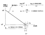
図6は図1のプローブ2,3間の距離と検出光量の対数との関係を示すグラフである。生体光計測装置では、プローブ2,3間の媒体物質の直線距離はx0=30mmである。光は、この中を多重散乱・吸収を受けながら、直線距離の5〜6倍(5倍としてr0=150mmとする)の実効光路長を進み、1/108〜1/109倍に減衰する。このような光の減衰曲線は、ランバート・ベールの法則が近似的に成り立ち、図6に示すように対数スケールでほぼ直線である。
FIG. 6 is a graph showing the relationship between the distance between the
生体内部情報の計測中に頭部で検出される検出光量の変化は1%のオーダーで、これが媒体物質、即ち大脳皮質内の血液量変化による光吸収率変化によるものである。これに等価の光量変化をもたらす実効光路長の変化は、図6に示す通りΔr=(150mm/9)×0.043=0.07mm程度となる。一方、位置測定の際には、プローブ2,3は、例えば1〜10mm程度変位するので、光路長の変化は5〜50mmで、光量の変化は1%よりもはるかに大きい。
The change in the amount of detected light detected by the head during the measurement of the in-vivo information is on the order of 1%, which is due to the change in light absorption rate due to the change in the amount of blood in the medium substance, that is, the cerebral cortex. As shown in FIG. 6, the change in the effective optical path length that brings about an equivalent light quantity change is about Δr = (150 mm / 9) × 0.043 = 0.07 mm. On the other hand, when the position is measured, the
従って、プローブ位置を変化させながら透過光量を測る条件と、プローブ間隔を変えずに透過光量を測る条件とでは、変動のスケールが違い、後者に比べて前者は大きいため、媒体物質の光透過率(光吸収率)を一定とみなして議論することは差し支えない。即ち、光透過率の変化による検出光量の変化量は、誤差と同等レベルであると考えられる。 Therefore, the conditions for measuring the amount of transmitted light while changing the probe position and the conditions for measuring the amount of transmitted light without changing the probe interval are different, and the former is larger than the latter. It is safe to argue that (light absorption rate) is constant. That is, the amount of change in the detected light amount due to the change in light transmittance is considered to be at the same level as the error.
また、計測部位、毛髪の有無、皮膚の色、年齢、性別、及びその他の要素によっても、dF/dxの値は変化するが、予め行った実験で求めたデータに基づいて補正を行えば、実用上十分な精度で位置決めを行うことができる。 In addition, the value of dF / dx varies depending on the measurement site, presence or absence of hair, skin color, age, gender, and other factors, but if correction is performed based on data obtained in a previous experiment, Positioning can be performed with practically sufficient accuracy.
次に、図7は図3の表示部15における第1の表示例(マップドグラフ形式表示)を示す説明図である。表示部15の画面には、頭部の左右2箇所の計測部位での計測結果が画面の左右に分けて表示されている。また、各計測部位について、12チャンネルの計測結果が12個のグラフ16として表示されている。各グラフ16には、各チャンネルにおける検出光量の時間変化が示されている。
Next, FIG. 7 is an explanatory diagram showing a first display example (mapped graph format display) on the
さらに、計測部位毎に、ボディマーク17も表示されている。さらにまた、位置測定の結果として、縦方向の破線で示す線状マーカ18a,18bにより、耳孔と頭頂とを結ぶ線、又は前頭葉と頭頂葉とを分ける中心溝と言われる脳溝の位置が表示されている。マーカ18a,18bの位置は、各グラフ16の中心座標を基準点として、2点又はそれ以上の計測から得られた位置情報に基づいて、ベストフィットとなるように決定される。線状マーカ18a,18bは、必要のないときには表示されないように選択できる。
Furthermore, a
また、図8は図3の表示部15における第2の表示例(濃淡地形図表示又はトポグラフィ画像表示)を示す説明図である。表示部15の画面には、頭部の左右2箇所の計測部位での計測結果が画面の左右(2列)に分けて表示されている。各計測部位での計測結果は、血液量情報を濃淡で示す上下3つの濃淡画像19として表示されており、上から順にオキシヘモグロビン、デオキシヘモグロビン、トータルヘモグロビンに関する情報が表示されている。血液量の変化は、色相の違い(例えば、増加している部位は赤、減少している部位は青、変化のない部位は白)で示される。
FIG. 8 is an explanatory diagram showing a second display example (shading topographic map display or topographic image display) on the
濃淡画像19内には、線状マーカ18c,18d,18eや点状マーカ18f,18gが重ねて表示されている。また、マーカ18c〜18gの近傍には、マーカの名称が添記されている。なお、Silvian fissure(シルビウス裂)は、前頭葉と側頭葉とを分ける脳溝、Broca(ブローカ野)は、言語を司ると言われる脳の部位、44−Brodmannは、ブロードマンの44をそれぞれ示している。マーカ18c〜18g及びその名称は、必要のないときには表示されないように選択できる。
In the
図7及び図8で示したマーカ18a〜18gは、位置測定により求められた特徴点の位置、又は複数の特徴点を結ぶ線、即ち頭皮上の基準点や基準線の位置を示している。
他の表示例として、正中線や耳孔−頭頂線を描き込んだ標準的な形状の人形の頭部の3次元グラフィック画像に、計測結果をその計測位置に対応して3次元的に貼り付けた表示を行うことも可能である。
The markers 18a to 18g shown in FIGS. 7 and 8 indicate the positions of feature points obtained by position measurement, or lines connecting a plurality of feature points, that is, the positions of reference points and reference lines on the scalp.
As another display example, the measurement result is pasted in a three-dimensional manner corresponding to the measurement position on a three-dimensional graphic image of a doll's head with a standard shape in which a median line or an ear canal-parietal line is drawn. It is also possible to display.
また、画面上の計測結果とマーカとの位置関係が、被検体の頭部の計測部位と特徴点との位置関係と同様になるように、計測結果の表示は、縮小・拡大が可能であるとともに、位置・方向の調整が可能になっている。 In addition, the display of the measurement result can be reduced or enlarged so that the positional relationship between the measurement result on the screen and the marker is the same as the positional relationship between the measurement part of the subject's head and the feature point. At the same time, the position and direction can be adjusted.
図9は図7及び図8のボディマーク17の種類を示す説明図である。ボディマーク17の全体形状は、計測位置に応じて、例えば左17a、右17b、前頭17c、後頭17d、頭頂17e等から選択することができる。また、ボディマーク17内のプローブホルダ形状は、使用するプローブホルダに応じて、例えば3×3マトリクスタイプ17f、3×5マトリクスタイプ17g、4×4マトリクスタイプ17h等から選択することができる。
FIG. 9 is an explanatory diagram showing the types of body marks 17 in FIGS. The overall shape of the
次に、計測及び解析の手順について説明する。図10は図1の生体光計測装置による計測及び解析の手順を示すフローチャートである。まず、電源をONにする(ステップS1)。次に、人体ファントムを用い、信号の送受信が正常であるかどうかを確認(試験)する(ステップS2)。信号の送受信が正常に行われることが確認されたら、被検体の頭部に装着部7を装着する(ステップS3)。即ち、プローブホルダ1を頭部に装着するとともに、プローブ2,3をプローブホルダ1に取り付ける。この後、必要に応じて、信号の送受信の確認、装置全体の状態のチェック、及び異常・不良への対応を実施する。
Next, measurement and analysis procedures will be described. FIG. 10 is a flowchart showing a procedure of measurement and analysis by the biological light measurement device of FIG. First, the power is turned on (step S1). Next, using a human phantom, it is confirmed (tested) whether or not signal transmission / reception is normal (step S2). When it is confirmed that signal transmission / reception is normally performed, the mounting
次に、制御部14の動作モードを位置測定モードとし、被検体の頭部における計測部位(即ち、プローブ2,3の取付位置)と頭皮上の特徴点との位置関係を測定する(ステップS4)。この後、制御部14の動作モードを通常計測モードとし、生体内部情報の計測、即ち大脳表面の血液量の計測を行う(ステップS5)。位置測定と生体内部情報の計測とは、逆の手順で行うことも可能である。また、位置測定及び生体内部情報の計測に際しては、各種のパラメータが設定される。さらに、位置測定及び生体内部情報の計測の後には、ボディマーク17の設定や取得データのセーブが行われる。
Next, the operation mode of the
ボディマーク17の設定は、表示部15の画面上でポインタを操作して設定画面を表示させ、全体形状の選択やプローブホルダ形状の選択を行う。ボディマーク17内のプローブホルダの位置は、ポインタを使って計測部位に近くなるようドラッグして調整することができる。このような選択・位置調整の後、OKボタンを押すことによりボディマーク設定が確定する。ボディマーク17の設定は、データ計測の後、データをセーブする前に適宜行うことができる。
The setting of the
上記のうち、被検体への装着部7の装着(ステップS3)から生体内部情報の計測(ステップS5)までの工程が計測に直接関わる工程であり、計測条件や被験者を変更して(ステップS6)、計測をまとめて実施する場合もある。
Among the above, the steps from the mounting of the mounting
生体内部情報の計測の後には、取得したデータの解析を行う(ステップS7)。そして、解析後にファイルの管理を行う(ステップS8)。ここで行うファイル管理には、例えば計測データの保存、解析データの保存、Hbファイルの保存、データの読み込み、データの削除、MO等の外部記録媒体へのデータの保存、外部記録媒体からのデータの読み込み、及びテキストデータの出力等が挙げられる。 After the measurement of the living body internal information, the acquired data is analyzed (step S7). Then, the file is managed after the analysis (step S8). The file management performed here includes, for example, measurement data storage, analysis data storage, Hb file storage, data reading, data deletion, data storage to an external recording medium such as MO, data from an external recording medium, etc. Reading, and outputting text data.
複数の計測条件や複数の被験者について計測をまとめて実施した場合、解析及びファイル管理についても、条件変更や被験者変更(ステップS9)を行いながらまとめて実施することができる。計測後にすぐに解析を行う場合には、図中破線矢印に示す流れとなる。また、新たに計測を行わず、保存された過去の計測済みデータの解析のみを行う場合は、電源をONにした後(ステップS1)、計測済みデータ解析(ステップS10)をすぐに行い、ファイル管理(ステップS8)を行えばよい。勿論、ファイル管理(ステップS8)のみを行うことも可能である。以上のような計測・解析が終了すると、電源をOFFにし(ステップS11)、全ての作業が終了する。 When measurement is collectively performed for a plurality of measurement conditions and a plurality of subjects, analysis and file management can also be performed collectively while changing conditions and subject changes (step S9). When analysis is performed immediately after measurement, the flow is indicated by a broken-line arrow in the figure. In addition, when only the analysis of the stored past measured data is performed without newly measuring, the measured data analysis (step S10) is immediately performed after turning on the power (step S1), and the file Management (step S8) may be performed. Of course, only file management (step S8) can be performed. When the above measurement / analysis is completed, the power is turned off (step S11), and all the operations are completed.
上記のような生体光計測装置では、被検体における計測部位の位置をより正確に測定することができる。これにより、プローブ2,3と頭皮上の特徴点との位置関係を計測データ内に反映させ、解析=診断時の情報として提供し、診断の精度を向上させることができる。即ち、別のモダリティのデータを使用することなく、プローブ2,3の位置と特徴点との関係を簡単な操作ながら十分な精度でモニタすることができ、計測結果を示す画像の読影が容易になる。また、複数の計測から得られた画像表示を比較・解析する際に、位置関係がはっきりして解析し易くなり、診断に対する信頼性が増す。
In the biological light measurement device as described above, the position of the measurement site in the subject can be measured more accurately. Thereby, the positional relationship between the
ここで、臨床で正確な診断を行う立場からは、計測に引き続いて解析を行うのが望ましい。これは、計測時に被検者の状態について銘記したい事柄があっても、その場で書き留めるなど、積極的な行動を取らない限り、解析までに時間が空くことにより記憶が失われてしまう可能性が高いからである。しかしながら、装置が臨床に使われている状況では、多数の計測を効率的に行う要求が強く、計測と解析とを別々に、それぞれをまとめて行うのは普通のことである。 Here, from the standpoint of accurate diagnosis in clinical practice, it is desirable to perform analysis subsequent to measurement. This means that even if there is something you want to keep in mind about the patient's condition at the time of measurement, if you do not take active action, such as writing it down on the spot, memory may be lost due to the time before analysis. Because it is expensive. However, in a situation where the apparatus is used in clinical practice, there is a strong demand for efficiently performing a large number of measurements, and it is normal to separately perform measurement and analysis separately.
これに対して、実施の形態1の生体光計測装置では、計測時の重要な情報の一つである計測部位の位置情報を装置内に残すことができるので、診断の精度を向上させることができる。 On the other hand, in the living body optical measurement device according to the first embodiment, the position information of the measurement site, which is one of important information at the time of measurement, can be left in the device, so that the accuracy of diagnosis can be improved. it can.
実施の形態2.
次に、図11はこの発明の実施の形態2による生体光計測装置の装着部を示す平面図である。図において、プローブホルダ1のプローブ2,3間の部分には、複数の開口部(窓)1aが設けられている。他の構成は、実施の形態1と同様である。
Next, FIG. 11 is a plan view showing a mounting portion of the biological light measurement device according to the second embodiment of the present invention. In the drawing, a plurality of openings (windows) 1 a are provided in a portion between the
このようなプローブホルダ1を用いることにより、例えば図11の特徴点P2のように、プローブホルダ1を被せた領域の内側に位置する特徴点P2上に光照射プローブ2を移動させて位置測定を実施することができ、特徴点の選択範囲を広げ、位置測定を容易にすることができる。
By using such a
なお、上記の例では、先に生体内部情報の計測位置での検出光量を計測してから、光照射プローブを特徴点に移動させたが、逆に、先に特徴点に光照射プローブを特徴点に置いたときの検出光量を計測してもよい。
また、上記の例では、光照射プローブを移動させたが、光照射プローブの位置を固定して光検出プローブを移動させてもよい。
In the above example, the light irradiation probe is moved to the feature point after measuring the detected light amount at the measurement position of the internal living body information first, but conversely, the light irradiation probe is first characterized as the feature point. The amount of light detected when placed at a point may be measured.
In the above example, the light irradiation probe is moved. However, the position of the light irradiation probe may be fixed and the light detection probe may be moved.
さらに、上記の例では、生体内部情報計測用のプローブを利用して位置測定を行ったが、位置測定専用のプローブ(照射用及び検出用のいずれか一方又は両方)を追加してもよい。このような専用プローブを追加する場合、光照射プローブ及び光検出プローブの取付部とは別に、複数の専用プローブ取付部をプローブホルダに設けてもよい。
さらにまた、専用プローブを用いる場合、専用プローブと光照射プローブ及び光検出プローブとの信号の相関を計測する回路を組み込み付加してもよい。このとき、位置測定用の制御部は、生体内部情報計測用の制御部と一体に構成しても、別体で構成してもよい。
Further, in the above example, the position measurement is performed using the probe for measuring internal biological information. However, a probe dedicated to position measurement (either one or both of irradiation and detection) may be added. When such a dedicated probe is added, a plurality of dedicated probe mounting portions may be provided in the probe holder separately from the mounting portions of the light irradiation probe and the light detection probe.
Furthermore, when a dedicated probe is used, a circuit that measures the correlation of signals between the dedicated probe, the light irradiation probe, and the light detection probe may be incorporated and added. At this time, the position measurement control unit may be configured integrally with the living body internal information measurement control unit or may be configured separately.
また、位置測定の際の光の波長や強度は、生体内部情報の計測時と同じでなくてもよい。
さらに、位置測定に関するデータは、生体内部情報の計測データと同じ記憶装置で収集しても、別の記憶装置で収集してもよい。
さらにまた、位置関係を求める特徴点の数は、計測部の位置を特定するための最小限の数に留める必要はなく、より多くの特徴点データを追加し、診断に利用することができる。
Further, the wavelength and intensity of light at the time of position measurement may not be the same as those at the time of measuring internal biological information.
Further, the data related to the position measurement may be collected by the same storage device as the measurement data of the internal biological information or may be collected by another storage device.
Furthermore, the number of feature points for obtaining the positional relationship need not be limited to the minimum number for specifying the position of the measurement unit, and more feature point data can be added and used for diagnosis.
実施の形態3.
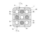
次に、図12はこの発明の実施の形態3による生体光計測装置の装着部を示す平面図である。図において、プローブホルダ1の表面には、直交格子状の目盛線20が付されている。
Next, FIG. 12 is a plan view showing a mounting portion of the biological light measurement device according to
この例では、頭皮上の特徴点に対する計測部位の位置を求める場合、特徴点と重なる目盛の座標を制御部14に入力する。これにより、制御部14は、計測結果の画像に重ねて特徴点の位置を表示部15に表示させることができる。例えば、図12の線分P1P2を特徴点とする場合、線分P1P2上にある目盛の座標、ここでは線分P1P2と交差するプローブホルダ1の2辺上の点Q1,Q2の座標(X1,Y1),(X2、Y2)を制御部14に入力すればよい。また、透明なプローブホルダ1に目盛線20を付ければ、プローブホルダ1の真下に位置する特徴点の座標も読むことができる。
In this example, when obtaining the position of the measurement site with respect to the feature point on the scalp, the coordinates of the scale overlapping the feature point are input to the
座標の入力は、キーボードで直接入力する方式のほか、PC画面上に点Q1,Q2を表示し、そのポインタをマウス又は矢印キーで移動させ、OKの指示で確定する間接的入力方式で行うことができる。特徴点の位置情報を含む計測データの扱いに関しては、実施の形態1と同様である。 In addition to the method of inputting the coordinates directly with the keyboard, the points Q1 and Q2 are displayed on the PC screen, the pointer is moved with the mouse or the arrow key, and the indirect input method is confirmed by the OK instruction. Can do. The handling of measurement data including position information of feature points is the same as in the first embodiment.
このような生体光計測装置によれば、被検体上の特徴点に対応する目盛の値を制御部14に入力することにより、特徴点に対する計測部位の位置が表示部15に表示され、光透過量の計測を行わずに、位置測定を容易に行うことができる。
According to such a biological light measurement device, by inputting a scale value corresponding to a feature point on the subject to the
なお、目盛は、直交格子状の座標に限定されるものではなく、極座標目盛(曲線座標)などでもよい。
また、目盛は、図12のようにプローブホルダの全体に設けても、縁部のみに設けてもよい。
The scale is not limited to the orthogonal grid coordinates, and may be a polar coordinate scale (curved coordinates).
Further, the scale may be provided on the entire probe holder as shown in FIG.
1 プローブホルダ、1a 開口部、2 光照射プローブ、3 光検出プローブ、7 装着部、14 制御部、15 表示部、20 目盛線。
DESCRIPTION OF
Claims (5)
上記光検出プローブでの検出光量を計測する制御部、及び
上記制御部による計測結果を表示する表示部
を備え、
上記制御部は、上記装着部上で間隔が既知の第1及び第2の点間で上記被検体に対して光を照射・検出したときの検出光量と、上記被検体上の特徴点と上記第1の点との間で上記被検体に対して光を照射・検出したときの検出光量との差から、上記第1の点と上記特徴点との間の距離を測定し、上記特徴点に対する計測部位の位置を上記表示部に表示させることを特徴とする生体光計測装置。 A mounting portion that has a plurality of light irradiation probes that irradiate light to the subject and a plurality of light detection probes that detect light returning from the subject, and is attached to the subject;
A control unit for measuring the amount of light detected by the light detection probe, and a display unit for displaying a measurement result by the control unit,
The control unit is configured to detect the amount of light when the subject is irradiated with light between the first and second points having a known interval on the mounting unit, and the feature point on the subject The distance between the first point and the feature point is measured from the difference between the detected light quantity when the subject is irradiated with light from the first point, and the feature point is measured. The biological light measuring device characterized by displaying the position of the measurement part to the above-mentioned display part.
上記光検出プローブでの検出光量を計測する制御部、及び
上記制御部による計測結果を表示する表示部
を備え、
上記プローブホルダには、目盛が付されており、
上記制御部は、上記被検体上の特徴点に対応する上記目盛の値を入力することにより、上記特徴点に対する計測部位の位置を上記表示部に表示させることを特徴とする生体光計測装置。 A probe holder, a plurality of light irradiation probes attached to the probe holder for irradiating light to the subject, and a plurality of light detection probes attached to the probe holder for detecting light returning from the subject, A mounting part to be mounted on the subject,
A control unit for measuring the amount of light detected by the light detection probe, and a display unit for displaying a measurement result by the control unit,
The probe holder has a scale,
The biological light measurement device, wherein the control unit displays the position of the measurement site with respect to the feature point on the display unit by inputting the scale value corresponding to the feature point on the subject.
Priority Applications (1)
| Application Number | Priority Date | Filing Date | Title |
|---|---|---|---|
| JP2005036372A JP4490303B2 (en) | 2005-02-14 | 2005-02-14 | Biological light measurement device |
Applications Claiming Priority (1)
| Application Number | Priority Date | Filing Date | Title |
|---|---|---|---|
| JP2005036372A JP4490303B2 (en) | 2005-02-14 | 2005-02-14 | Biological light measurement device |
Publications (3)
| Publication Number | Publication Date |
|---|---|
| JP2006218196A JP2006218196A (en) | 2006-08-24 |
| JP2006218196A5 JP2006218196A5 (en) | 2007-06-14 |
| JP4490303B2 true JP4490303B2 (en) | 2010-06-23 |
Family
ID=36980889
Family Applications (1)
| Application Number | Title | Priority Date | Filing Date |
|---|---|---|---|
| JP2005036372A Expired - Fee Related JP4490303B2 (en) | 2005-02-14 | 2005-02-14 | Biological light measurement device |
Country Status (1)
| Country | Link |
|---|---|
| JP (1) | JP4490303B2 (en) |
Families Citing this family (5)
| Publication number | Priority date | Publication date | Assignee | Title |
|---|---|---|---|---|
| JP2010252906A (en) * | 2009-04-22 | 2010-11-11 | Hitachi Medical Corp | Biological light measuring instrument |
| CN102469993B (en) * | 2009-07-21 | 2014-07-16 | 株式会社岛津制作所 | Organism optical measurement device |
| JP2013059437A (en) * | 2011-09-13 | 2013-04-04 | Shimadzu Corp | Optical biometric apparatus |
| US20150342461A1 (en) * | 2012-11-14 | 2015-12-03 | Shimadzu Corporation | Optical biometric device and position measuring device used therein |
| JP2015150186A (en) * | 2014-02-14 | 2015-08-24 | 株式会社日立メディコ | Biophotonic measurement apparatus |
-
2005
- 2005-02-14 JP JP2005036372A patent/JP4490303B2/en not_active Expired - Fee Related
Also Published As
| Publication number | Publication date |
|---|---|
| JP2006218196A (en) | 2006-08-24 |
Similar Documents
| Publication | Publication Date | Title |
|---|---|---|
| US10299710B2 (en) | Organism optical measurement device | |
| JP4968167B2 (en) | Optical biometric apparatus and holder arrangement support system used therefor | |
| EP1652470A1 (en) | Optical measuring instrument for living body | |
| JP5347448B2 (en) | Biometric device | |
| JP4490303B2 (en) | Biological light measurement device | |
| US20180360307A1 (en) | Apparatus for angiographic optical coherence tomography in retina or choroid, and method for diagnosing diseases by using same | |
| JP5159893B2 (en) | Biological light measurement device and light irradiation position and light detection position or measurement channel position display method | |
| KR102575294B1 (en) | Breast cancer diagnosis system | |
| JP4411208B2 (en) | Biological light measurement device | |
| JP2007196001A (en) | Optical measuring device for living body | |
| JP4978485B2 (en) | Optical biometric device | |
| JP4428786B2 (en) | Biological light measurement device | |
| KR101961147B1 (en) | Apparatus for measurements non-invasive blood sugar, method for measurements non-invasive blood glucose using the apparatus | |
| JP4327017B2 (en) | Screen reconstruction method | |
| WO2014076795A1 (en) | Optical biometric device | |
| RU2804287C2 (en) | Method for registration and processing of optical biopsy data in dynamic mode | |
| JP5729490B2 (en) | Optical biological measurement device | |
| JP2005328933A (en) | Transcranial brain function measuring apparatus | |
| JP3952275B2 (en) | Biological light measurement device | |
| JP5347312B2 (en) | Light measuring device |
Legal Events
| Date | Code | Title | Description |
|---|---|---|---|
| A521 | Request for written amendment filed |
Free format text: JAPANESE INTERMEDIATE CODE: A523 Effective date: 20070417 |
|
| A621 | Written request for application examination |
Free format text: JAPANESE INTERMEDIATE CODE: A621 Effective date: 20070417 |
|
| RD04 | Notification of resignation of power of attorney |
Free format text: JAPANESE INTERMEDIATE CODE: A7424 Effective date: 20091027 |
|
| TRDD | Decision of grant or rejection written | ||
| A01 | Written decision to grant a patent or to grant a registration (utility model) |
Free format text: JAPANESE INTERMEDIATE CODE: A01 Effective date: 20100302 |
|
| A01 | Written decision to grant a patent or to grant a registration (utility model) |
Free format text: JAPANESE INTERMEDIATE CODE: A01 |
|
| A61 | First payment of annual fees (during grant procedure) |
Free format text: JAPANESE INTERMEDIATE CODE: A61 Effective date: 20100401 |
|
| FPAY | Renewal fee payment (event date is renewal date of database) |
Free format text: PAYMENT UNTIL: 20130409 Year of fee payment: 3 |
|
| R150 | Certificate of patent or registration of utility model |
Free format text: JAPANESE INTERMEDIATE CODE: R150 |
|
| FPAY | Renewal fee payment (event date is renewal date of database) |
Free format text: PAYMENT UNTIL: 20140409 Year of fee payment: 4 |
|
| S111 | Request for change of ownership or part of ownership |
Free format text: JAPANESE INTERMEDIATE CODE: R313111 |
|
| S533 | Written request for registration of change of name |
Free format text: JAPANESE INTERMEDIATE CODE: R313533 |
|
| R350 | Written notification of registration of transfer |
Free format text: JAPANESE INTERMEDIATE CODE: R350 |
|
| LAPS | Cancellation because of no payment of annual fees |