JP2015150186A - Biophotonic measurement apparatus - Google Patents
Biophotonic measurement apparatus Download PDFInfo
- Publication number
- JP2015150186A JP2015150186A JP2014026092A JP2014026092A JP2015150186A JP 2015150186 A JP2015150186 A JP 2015150186A JP 2014026092 A JP2014026092 A JP 2014026092A JP 2014026092 A JP2014026092 A JP 2014026092A JP 2015150186 A JP2015150186 A JP 2015150186A
- Authority
- JP
- Japan
- Prior art keywords
- light
- probe
- light source
- distance
- light receiving
- Prior art date
- Legal status (The legal status is an assumption and is not a legal conclusion. Google has not performed a legal analysis and makes no representation as to the accuracy of the status listed.)
- Pending
Links
Images


Abstract
Description
本願発明は、近赤外光を生体に照射し、生体内部を通過或いは生体内部で反射した光を計測し、生体内部の血液循環、血行動態及びヘモグロビン量変化を計測する生体光計測装置に関するものである。 The present invention relates to a biological light measuring device that irradiates a living body with near-infrared light, measures light that has passed through or reflected inside the living body, and measures blood circulation, hemodynamics, and changes in the amount of hemoglobin inside the living body. It is.
生体光計測装置は、被検体に光を照射し、被検体を通過した光を計測する光照射・計測部と、前記光照射・計測部の計測データを処理して生体光計測画像を生成する信号処理部と、前記光照射・計測部の被検体への光照射位置および被検体からの通過光の取り出し位置を測定する位置計測部とを有し、前記光照射・計測部は、複数の光ファイバと、前記複数の光ファイバにそれぞれ取り付けられた複数の光ファイバプラグと、被検体の測定部位に着脱可能に固定され、前記複数の光ファイバプラグを保持するホルダとを備えるものである。前記位置計測部は、移動型位置センサと、前記移動型位置センサに取り付けられ前記ホルダに保持された前記複数の光ファイバプラグと着脱可能に係合する形状である係合部材とを具備する。これによって、生体光計測装置の光ファイバの先端が被検体に当接した状態で、精度よく光ファイバの先端位置の測定が可能になる(例えば、特許文献1参照)。 The biological light measurement device irradiates a subject with light, measures a light irradiation / measurement unit that measures light that has passed through the subject, and processes measurement data of the light irradiation / measurement unit to generate a biological light measurement image A signal processing unit, and a position measurement unit that measures a light irradiation position on the subject of the light irradiation / measurement unit and a position where a passing light is extracted from the subject, and the light irradiation / measurement unit includes a plurality of light irradiation / measurement units, An optical fiber, a plurality of optical fiber plugs attached to the plurality of optical fibers, and a holder that is detachably fixed to a measurement site of a subject and holds the plurality of optical fiber plugs. The position measuring unit includes a movable position sensor and an engaging member that is detachably engaged with the plurality of optical fiber plugs attached to the movable position sensor and held by the holder. As a result, the tip position of the optical fiber can be accurately measured in a state where the tip of the optical fiber of the biological light measurement device is in contact with the subject (see, for example, Patent Document 1).
しかしながら、特許文献1では、検者が計測対象に光源プローブと受光プローブを任意に配置した場合、検者が三次元的な空間を測定する位置センサを使って光源プローブと受光プローブの三次元的な空間位置を測定することが必要である。また、検者が配置された複数の光源プローブと受光プローブの位置関係考慮し各プローブ間にチャンネル番号を割り付けて、割り付けたチャンネル番号に関する情報を信号処理するパーソナルコンピュータ(PC)に入力することが必要である。これらのように、計測対象に任意に配置された光源プローブと受光プローブの配置情報に関して、プローブの数が増え(計測対象領域が増え)ていき、その結果各プローブ間の組み合わせによる計測チャンネルが数10チャンネル、数100チャンネルに及ぶことが想定される。しかしそれらに関してひとつひとつ、間違わずに空間位置測定をすることやその結果をPCへ入力することは検者にとって煩雑な操作である。 However, in Patent Document 1, when an examiner arbitrarily arranges a light source probe and a light receiving probe on a measurement target, the examiner uses a position sensor that measures a three-dimensional space to measure the three-dimensional relationship between the light source probe and the light receiving probe. It is necessary to measure the spatial position. It is also possible to assign a channel number between each probe in consideration of the positional relationship between a plurality of light source probes and light receiving probes arranged by an examiner, and to input information on the assigned channel number to a personal computer (PC) that performs signal processing. is necessary. As described above, the number of probes increases with respect to the arrangement information of the light source probe and the light receiving probe arbitrarily arranged on the measurement target (the measurement target area increases), and as a result, the number of measurement channels by the combination between each probe increases. It is expected to cover 10 channels and several hundred channels. However, it is a complicated operation for the examiner to measure the spatial position without making a mistake and to input the result to the PC.
そこで、本願発明の目的は、光源プローブと受光プローブの三次元的な空間位置の測定あるいはそれらの情報の入力の煩雑さを解消することが可能な生体光計測装置を提供することにある。 SUMMARY OF THE INVENTION An object of the present invention is to provide a living body light measuring apparatus that can eliminate the complexity of measuring the three-dimensional spatial positions of a light source probe and a light receiving probe or inputting the information.
上記目的を達成するために、本発明の生体光計測装置は、複数の光源プローブを用いて近赤外光を照射する光源部と、複数の受光プローブを用いて被検体の複数の測定点における通過光の信号強度を計測し、測定点毎の通過光の信号を計測する光計測部と、前記信号をデータ処理する信号処理部と、前記データ処理の結果を表示する表示部と、入出力部からの入力パラメータを受けて前記光源部、前記光計測部、前記信号処理部及び前記表示部を制御する制御部と、を備えた生体光計測装置であって、前記制御部は複数の光源プローブのうちの所定の光源プローブと、当該光源プローブと受光プローブとの距離において、ファントムを介した前記光源プローブからの発光を前記受光プローブで受光して複数の距離に対する予備計測値を計測し、前記予備計測値のうちの一を基準距離に対する基準出力値とし、前記基準距離及び前記基準距離と異なるその他の距離の前記予備計測値の出力値を、前記基準距離と異なるその他の距離と前記基準距離と異なるその他の距離と前記基準距離と異なるその他の距離と前記基準距離に対応づけて記憶部に記憶させ、前記被検体に配置された前記光源プローブと前記受光プローブに対して前記被検体を介して前記光源プローブからの発光を前記受光プローブで受光した信号強度の測定値を計測し、前記測定値と前記予備計測値とを比較し、それらの比較結果に基づき前記光源プローブと前記受光プローブの距離を演算することを特徴とする。 In order to achieve the above object, a biological light measurement apparatus of the present invention includes a light source unit that irradiates near infrared light using a plurality of light source probes, and a plurality of measurement points of a subject using a plurality of light receiving probes. An optical measurement unit that measures the signal intensity of the passing light and measures a passing light signal at each measurement point, a signal processing unit that processes the signal, a display unit that displays the result of the data processing, and an input / output A biological light measurement device comprising: a light source unit, a light measurement unit, a signal processing unit, and a control unit that controls the display unit in response to input parameters from a unit, wherein the control unit includes a plurality of light sources Light emission from the light source probe via a phantom is received by the light receiving probe at a distance between a predetermined light source probe of the probes and the light source probe and the light receiving probe, and preliminary measurement values for a plurality of distances are measured. One of the preliminary measurement values is set as a reference output value with respect to a reference distance, and the output value of the preliminary measurement value at another distance different from the reference distance and the reference distance is set to another distance different from the reference distance and the reference The other distance different from the distance, the other distance different from the reference distance, and the reference distance are stored in the storage unit, and the object is attached to the light source probe and the light receiving probe arranged in the object. A measurement value of the signal intensity received by the light receiving probe through the light source probe is measured, the measured value is compared with the preliminary measurement value, and the light source probe and the light receiving probe are compared based on the comparison result. The distance is calculated.
本願発明によれば、光源プローブと受光プローブの三次元的な空間位置の測定あるいはそれらの情報の入力の煩雑さを解消することが可能な生体光計測装置を提供するという効果を奏する。 According to the present invention, there is an effect of providing a living body light measurement device capable of eliminating the complexity of measuring the three-dimensional spatial position of the light source probe and the light receiving probe or inputting the information.
以下、添付図面に従って本願発明の好ましい実施形態について説明する。なお、以下の説明及び添付図面において、同一の機能構成を有する構成要素については、同一の符号を付することにより重複説明を省略することにする。 Hereinafter, preferred embodiments of the present invention will be described with reference to the accompanying drawings. In the following description and the accompanying drawings, the same reference numerals are given to the constituent elements having the same functional configuration, and redundant description will be omitted.
[各実施例共通の生体光計測装置の構成]
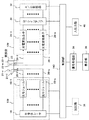
図1は、本発明の生体光計測装置の構成例を示す図である。生体光計測装置は、近赤外光を生体(被検体)内に照射し、被検体の表面近傍から反射或いは被検体内を通過した光(以下、単に通過光という)を検出し、光の強度に対応する電気信号を発生する装置である。生体光計測装置は、図1に示すように、光源部100と、光計測部120と、制御部14と、信号処理部34と、表示部36と、記憶部38と、入出力部40と、を備える。
[Configuration of living body light measurement device common to each embodiment]
FIG. 1 is a diagram illustrating a configuration example of a biological light measurement device of the present invention. The biological light measurement device irradiates a living body (subject) with near-infrared light, detects light reflected from the vicinity of the surface of the subject or passed through the subject (hereinafter simply referred to as passing light), It is a device that generates an electrical signal corresponding to the intensity. As shown in FIG. 1, the biological light measurement device includes a
光源部100は、近赤外光を照射するものであって、所定の波長の光を放射する半導体レーザ16と、半導体レーザ16が発生する光を複数の異なる周波数で変調するための変調器を備えた複数の光モジュール18-1、・・・、18-nと、光モジュール18-1、・・・、18-nと光源プローブ21-1、・・・、21-nを接続する光ファイバ20-1、・・・、20-nと、光ファイバ20-1、・・・、20-nを介して各光モジュール18-1、・・・、18-nの出力光を被検体の頭部に照射する光源プローブ21-1、・・・、21-nと、光源プローブ21-1、・・・、21-nを被検体の頭部に固定するプローブホルダ23と、を備える。
The
各光モジュール18-1、・・・、18-nからの光の波長は被検体内の注目物質の分光特性によるが、還元ヘモグロビンと酸化ヘモグロビンの濃度から酸素飽和度や血液量を計測する場合には600nm〜1400nmの波長範囲の光の中から1あるいは複数波長選択して用いる。具体的には、光源部100は被検体の血液中の酸素化ヘモグロビンと脱酸素化ヘモグロビンの2種類の測定対象に対応して2種類の波長、例えば780nm及び830nmの光を発生するように構成され、これら2種類の波長の光は合成され一つの照射位置から照射される。
The wavelength of light from each optical module 18-1, ..., 18-n depends on the spectral characteristics of the substance of interest in the subject, but when measuring oxygen saturation and blood volume from the concentration of reduced hemoglobin and oxidized hemoglobin Is used by selecting one or a plurality of wavelengths from light in the wavelength range of 600 nm to 1400 nm. Specifically, the
光計測部120は、被検体の通過光を受光し、電気信号に変換するものであって、プローブホルダ23に固定され被検体の通過光を受光する受光プローブ22-1、・・・、22-nと、受光プローブ22-1、・・・、22-nと光電変換素子28-1、・・・、28-nを接続する検出用光ファイバ26-1、・・・、26-nと、検出用光ファイバ26-1、・・・、26-nを介して受光プローブ22-1、・・・、22-nからの通過光のそれぞれ光量を電気量に変換するフォトダイオード等の光電変換素子28-1、・・・、28-nと、光電変換素子28-1、・・・、28-nからの電気信号を入力し、光照射位置に対応した変調信号を選択的に検出するロックインアンプ30と、ロックインアンプ30の出力信号をデジタル信号に変換するA/D変換器32と、を備える。
The
制御部14は光源部100及び光計測部120の駆動を制御するもので、光源部100及び光計測部120のそれぞれに次の制御を行わせる。
The
制御部14は光源部100に2種類の測定対象に対応して2種類の波長の光を発生させ、これら2種類の波長の光は合成され一つの照射位置から照射させる。次に、制御部14は光計測部120のロックインアンプ30に光照射位置とこれら2種類の波長に対応した変調信号を選択的に検出させる。光照射位置と検出位置との間の点(計測点)の数の2倍のチャンネル数の酸素化ヘモグロビン又は脱酸素化ヘモグロビンのヘモグロビン量変化信号が得られる。
The
また、デジタル信号に変換されたヘモグロビン量変化信号を処理し、酸素化ヘモグロビン濃度変化、脱酸素化ヘモグロビン濃度変化、全ヘモグロビン濃度変化などをチャンネル毎に示すグラフやそれを被検体の二次元画像上にプロットした画像を作成する信号処理部34と、信号処理部34の処理結果を表示する表示部36と、信号処理部34の処理に必要なデータや処理結果を記憶するための記憶部38と、装置の動作に必要な種々の指令を入力するための端末として入出力部40を備えている。
Also, the hemoglobin amount change signal converted into a digital signal is processed, and a graph showing the change in oxygenated hemoglobin concentration, change in deoxygenated hemoglobin concentration, change in total hemoglobin concentration, etc. for each channel is displayed on the two-dimensional image of the subject. A signal processing unit 34 for creating an image plotted on the display, a
次に、本発明の実施例1について図1乃至図3を用いて説明する。実施例1では光源プローブと受光プローブの間の距離を求める例を示している。 Next, Example 1 of the present invention will be described with reference to FIGS. The first embodiment shows an example in which the distance between the light source probe and the light receiving probe is obtained.
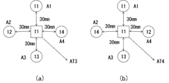
図2は図1の記憶部38に記憶される光源プローブと受光プローブ間の距離と信号の出力比の関係を説明する図である。この図2には、光源プローブから受光プローブへファントムを介して得られる信号に基準距離(例えば30mm)の出力を1としたとき、他の距離の基準距離に対する出力比の関係を説明している。図3は実施例1を説明するための光源プローブと受光プローブの配置例を示す図である。
FIG. 2 is a diagram for explaining the relationship between the distance between the light source probe and the light receiving probe stored in the
[実施例1の生体光計測装置の特徴部分の構成]
図1に示される制御部14には、上記説明した機能に次の機能が追加される。
[Configuration of Characteristic Part of Biological Optical Measurement Device of Example 1]
In the
(1)予備計測の実施:複数の光源プローブ21-1、・・・、21-nのうちの所定の光源プローブと、当該光源プローブとの間で距離を特定したい受光プローブの複数の距離においてファントムを介した前記光源プローブからの発光を前記受光プローブで受光した予備計測値を計測する。 (1) Preliminary measurement: At a plurality of distances of a predetermined light source probe among a plurality of light source probes 21-1,..., 21-n and a light receiving probe whose distance is to be specified. A preliminary measurement value obtained by receiving light emitted from the light source probe via the phantom by the light receiving probe is measured.
(2)予備計測値の出力比への換算:前記予備計測値のうちの基準距離(例えば30mm)の出力値を基準出力値とし、前記基準距離を除くその他距離に対する出力値と基準出力値の比を出力比として演算する。ここでは、前記基準距離の出力比を1と換算し、前記その他距離の出力比はそれぞれ前記基準距離の換算値によって求められる。光源ー受光プローブ間距離[mm]対出力比は、グラフで示せば図2の38aで示すようになり、表で示せば図2の38bで示すようになる。今後距離として説明する15、30、45、60mmはそれぞれ、8.8333、1.0000、0.16358、0.02235の出力比となる。この出力比は、最も小さい値の60mmを1として換算すれば、15、30、45、60mmはそれぞれ395、45、7、1となる。 (2) Conversion of the preliminary measurement value to the output ratio: The output value of the reference distance (for example, 30 mm) of the preliminary measurement value is used as the reference output value, and the output value and the reference output value for other distances excluding the reference distance The ratio is calculated as the output ratio. Here, the output ratio of the reference distance is converted to 1, and the output ratios of the other distances are respectively obtained from the converted values of the reference distance. The distance [mm] between the light source and the light receiving probe versus the output ratio is as shown by 38a in FIG. 2 when shown in a graph, and as shown by 38b in FIG. 2 as shown in a table. In the future, 15, 30, 45, and 60mm, which will be described as distances, will be output ratios of 8.8333, 1.000, 0.16358, and 0.02235, respectively. This output ratio is converted to 395, 45, 7, and 1 for 15, 30, 45, and 60 mm, respectively, when the smallest value of 60 mm is converted to 1.
(3)予備計測値の出力比の記憶:前記基準距離及びその他の距離と対応づけて前記予備計測値の出力比を記憶部38に記憶させる。
(3) Storage of output ratio of preliminary measurement values: The output ratio of the preliminary measurement values is stored in the
なお、上記の(1)乃至(3)は、予め予備計測の実施、予備計測値の出力比への換算及び予備計測値の出力比の記憶を行っていれば、毎回行う必要はない。 Note that the above (1) to (3) need not be performed every time as long as preliminary measurement is performed, conversion of the preliminary measurement value into the output ratio and storage of the output ratio of the preliminary measurement value are performed in advance.
(4)距離推定計測の実施:被検体に配置された前記光源プローブと前記受光プローブに対して前記被検体を介して前記光源プローブからの発光を前記受光プローブで受光した測定値を計測する。 (4) Implementation of distance estimation measurement: Measured values of light emitted from the light source probe received by the light receiving probe via the subject with respect to the light source probe and the light receiving probe arranged on the subject.
(5)プローブ間距離の演算:前記測定値と前記予備計測値のそれぞれの信号強度を比較し、それぞれの信号強度の比較結果に基づき前記光源プローブと前記受光プローブの距離を演算する。 (5) Calculation of distance between probes: The signal strengths of the measurement value and the preliminary measurement value are compared, and the distance between the light source probe and the light receiving probe is calculated based on the comparison result of the signal strengths.
[実施例1の生体光計測装置の特徴部分の動作]
[予備計測の実施]
検者は入出力部40の端末を操作して予備計測の実行開始を入力する。実行開始の方法は、例えば、端末に「予備計測」を示すアイコンが表示されており、マウスなどのポインティングデバイスを用いて「予備計測」のアイコン上にカーソルを移動させ、カーソルが「予備計測」のアイコンと重なったときに検者がクリックする(図示省略)。制御部14は入力された「予備計測」を受けて、被検体を模したファントムを使用した計測を行い、距離30mmでの光受信強度(出力)を1として他の距離の光受信強度を測定する。
[Operation of Characteristic Part of Biological Optical Measurement Device of Example 1]
[Preliminary measurement]
The examiner operates the terminal of the input /
[予備計測値の出力比への換算]
制御部14は、距離30mmでの光受信強度と他の距離の光受信強度の比を予備計測値の出力比として換算する。
[Conversion of preliminary measurement value to output ratio]
The
[予備計測の出力比の記憶]
制御部14は前記基準距離及びその他の距離と対応づけて前記予備計測値の出力比を記憶部38に記憶させる。
[Memorization of output ratio of preliminary measurement]
The
なお、上記の(1)乃至(3)は、予め予備計測の実施、予備計測値の出力比への換算及び予備計測値の出力比の記憶を行っていれば、[予備計測の実施]、[予備計測値の出力比への換算]及び[予備計測の出力比の記憶]の実行を省略できる。 Note that the above (1) to (3) are performed in advance if preliminary measurement is performed, conversion of the preliminary measurement value to the output ratio and storage of the output ratio of the preliminary measurement value are performed, [Conversion of preliminary measurement value to output ratio] and [Storage of preliminary measurement output ratio] can be omitted.
[プローブの任意配置]
検者は光源プローブ21-1、・・・、21-n、受光プローブ22-1、・・・、22-nをプローブホルダ23に固定された状態で、被検体の頭部に装着する。検者は光源プローブ21-1、・・・、21-n、受光プローブ22-1、・・・、22-n間の距離を任意に設定する。光源プローブと受光プローブの配置の仕方は次の方法がある。
[Optional placement of probes]
The examiner puts the light source probes 21-1,..., 21-n and the light receiving probes 22-1, ..., 22-n on the head of the subject while being fixed to the
(1)略等距離の配置:図3(a)に示すように、丸で示す第11チャンネル、第12チャンネル、第13チャンネル、第14チャンネルの光源プローブに囲まれ、その中心位置に第11チャンネルの受光プローブを第11乃至第14チャンネルと検者の目視で等距離を配置する。ここでは等距離の仮想値を30mmとする。 (1) Almost equidistant arrangement: As shown in FIG. 3 (a), the eleventh channel, the twelfth channel, the thirteenth channel, and the fourteenth channel light source probes surrounded by circles are surrounded by the eleventh channel at the center position. The light receiving probes of the channels are arranged equidistant from the eleventh to fourteenth channels by visual inspection. Here, the virtual value of equidistant is 30 mm.
(2)異なる距離の配置:図3(b)に示すように、丸で示す第11チャンネル、第12チャンネル、第13チャンネル、第14チャンネルの光源プローブに囲まれ、その中心位置に第11チャンネルの受光プローブを第11乃至第14チャンネルと検者の目視でそれぞれ異なる距離を配置する。ここで距離の仮想値は第11チャンネルの受光プローブを起点として、第11チャンネルの光源プローブへは30mmとする。また、第12チャンネルの光源プローブへは15mmとし、第13チャンネルの光源プローブへは45mmとし、第14チャンネルの光源プローブへは60mmとする。 (2) Arrangement of different distances: As shown in Fig. 3 (b), the eleventh channel, the twelfth channel, the thirteenth channel, and the fourteenth channel light source probes surrounded by circles are surrounded by the eleventh channel at the center position. The light receiving probes are arranged at different distances from the eleventh to fourteenth channels by visual inspection of the examiner. Here, the virtual value of the distance is 30 mm for the eleventh channel light source probe, starting from the eleventh channel light receiving probe. Also, 15 mm is set for the 12th channel light source probe, 45 mm is set for the 13th channel light source probe, and 60 mm is set for the 14th channel light source probe.
[距離推定計測の実施]
制御部14は被検体に配置された前記光源プローブと前記受光プローブに対して前記被検体を介して前記光源プローブからの発光を前記受光プローブで受光した測定値を計測する。
[Performance estimation]
The
ここで、前記第11チャンネルの受光プローブの信号強度は、次に示される。
(1)略等距離の配置:光源プローブと受光プローブの間の光減衰量αがほぼ同じと仮定した場合、検出される信号強度ATは第11乃至14チャンネルの光源プローブのそれぞれの強度A1〜A4の合計となる。
Here, the signal intensity of the light receiving probe of the eleventh channel is shown as follows.
(1) Almost equidistant arrangement: When it is assumed that the light attenuation α between the light source probe and the light receiving probe is substantially the same, the detected signal intensity AT is the intensity A1 of each of the 11th to 14th channel light source probes. This is the sum of A4.
すわなち
AT=α(A1+A2+A3+A4)・・・(1)
となる。
ここでA1〜A4はほぼ同じ強度と仮定しているため、以下に近似される。
AT=4αA1・・・(2)
Swanachi
AT = α (A1 + A2 + A3 + A4) (1)
It becomes.
Here, since A1 to A4 are assumed to have substantially the same intensity, they are approximated as follows.
AT = 4αA1 ... (2)
(2)異なる距離の配置:光源プローブと受光プローブの間の光減衰量αがほぼ同じと仮定した場合、検出される信号強度ATは、略等距離の配置と同様に第11乃至14チャンネルの光源プローブのそれぞれの信号強度A1〜A4の合計となる。 (2) Arrangement of different distances: Assuming that the light attenuation α between the light source probe and the light receiving probe is almost the same, the detected signal intensity AT is the same as that of the equidistant arrangement of the 11th to 14th channels. This is the sum of the signal intensities A1 to A4 of the light source probes.
しかし図3(a)の場合と異なり、この信号強度A1〜A4から受光する実際の信号強度は異なっている。出力比を計算するため、最も長距離のA4からの受光する信号強度を1とした場合の、各信号強度の関係は図2の38bの換算値に示すように、以下のとおりである。
A1:A2:A3:A4=45:395:7:1・・・(3)
However, unlike the case of FIG. 3 (a), the actual signal intensity received from these signal intensities A1 to A4 is different. In order to calculate the output ratio, when the signal intensity received from the longest distance A4 is 1, the relationship between the signal intensities is as follows, as shown in the converted value of 38b in FIG.
A1: A2: A3: A4 = 45: 395: 7: 1 ... (3)
[プローブ間距離の演算]
制御部14は前記測定値と前記予備計測値のそれぞれの信号強度を比較し、それぞれの信号強度の比較結果に基づき前記光源プローブと前記受光プローブの距離を演算する。
[Calculation of distance between probes]
The
(1)略等距離の配置:制御部14は第11チャンネルの受光プローブに対し第11チャンネルの光源プローブのみを選択的に発光させ、第11チャンネルの受光プローブの信号強度A1がATの1/4に近似する値であるか否か判定する。判定の結果、近似する値であれば、第11チャンネルの受光プローブと第11チャンネルの光源プローブの距離を30mmと推定する。
(1) Almost equidistant arrangement: The
同様に、順次、第12チャンネルの光源プローブのみ、第13チャンネルの光源プローブのみ、第14チャンネルの光源プローブのみについても選択的に発光させ、第12チャンネルの受光プローブの信号強度A2、第13チャンネルの受光プローブの信号強度A3、第14チャンネルの受光プローブの信号強度A4がそれぞれATの1/4に近似する値であるか否か判定する。判定の結果、近似する値であれば、第12チャンネル、第13チャンネル、第14チャンネルの受光プローブと第11チャンネルの光源プローブの距離を30mmと推定する。 Similarly, only the light source probe of the 12th channel, only the light source probe of the 13th channel, and only the light source probe of the 14th channel are selectively made to emit light, the signal intensity A2 of the light receiving probe of the 12th channel, the 13th channel It is determined whether the signal intensity A3 of the light receiving probe and the signal intensity A4 of the light receiving probe of the 14th channel are values approximate to 1/4 of AT, respectively. If the result of determination is an approximate value, the distance between the light receiving probes of the 12th channel, 13th channel and 14th channel and the light source probe of the 11th channel is estimated to be 30 mm.
(2)異なる距離の配置:
制御部14は第11チャンネルの受光プローブに対し第11乃至14チャンネルの光源プローブ全て発光させた状態から選択的に消光させ、第11チャンネルの受光プローブの信号強度A1を消光したAT1がATの403/448(=45+395+7+1)に近似する値であるか否か判定する。判定の結果、近似する値であれば、第11チャンネルの受光プローブと第11チャンネルの光源プローブの距離を30mmと推定する。
(2) Different distance arrangement:
The
同様に、制御部14は第12チャンネルの受光プローブに対し第11乃至14チャンネルの光源プローブ全て発光させた状態から選択的に消光させ、第12チャンネルの受光プローブの信号強度A2を消光したAT2がATの53/448(=45+395+7+1)に近似する値であるか否か判定する。判定の結果、近似する値であれば、第11チャンネルの受光プローブと第12チャンネルの光源プローブの距離を15mmと推定する。
Similarly, the
また、同様に、制御部14は第13チャンネルの受光プローブに対し第11乃至14チャンネルの光源プローブ全て発光させた状態から選択的に消光させ、第13チャンネルの受光プローブの信号強度A3を消光したAT3がATの441/448(=45+395+7+1)に近似する値であるか否か判定する。判定の結果、近似する値であれば、第11チャンネルの受光プローブと第13チャンネルの光源プローブの距離を45mmと推定する。
Similarly, the
さらにまた、同様に、制御部14は第14チャンネルの受光プローブに対し第11乃至14チャンネルの光源プローブ全て発光させた状態から選択的に消光させ、第14チャンネルの受光プローブの信号強度A4を消光したAT4がATの447/448(=45+395+7+1)に近似する値であるか否か判定する。判定の結果、近似する値であれば、第11チャンネルの受光プローブと第14チャンネルの光源プローブの距離を60mmと推定する。
Further, similarly, the
[実施例1の生体光計測装置の効果]
以上説明したように実施例1の生体光計測装置は、複数の光源プローブ21-1、・・・、21-nを用いて近赤外光を照射する光源部100と、複数の受光プローブ22-1、・・・、22-nを用いて被検体の複数の測定点における通過光の信号強度を計測し、測定点毎の通過光の信号を計測する光計測部120と、前記信号をデータ処理する信号処理部34と、前記データ処理の結果を表示する表示部36と、入出力部40からの入力パラメータを受けて前記光源部100、前記光計測部120、前記信号処理部34及び前記表示部36を制御する制御部14と、を備えた生体光計測装置であって、前記制御部14は複数の光源プローブ21-1、・・・、21-nのうちの所定の光源プローブと、当該光源プローブ21-1、・・・、21-nと受光プローブ22-1、・・・、22-nとの距離において、ファントムを介した前記光源プローブからの発光を前記受光プローブで受光して複数の距離に対する予備計測値を計測し、前記予備計測値のうちの一を基準距離に対する基準出力値とし、前記基準距離及び前記基準距離と異なるその他の距離の前記予備計測値の出力値を、前記基準距離と異なるその他の距離と前記基準距離と異なるその他の距離と前記基準距離に対応づけて記憶部に記憶させ、前記被検体に配置された前記光源プローブと前記受光プローブに対して前記被検体を介して前記光源プローブからの発光を前記受光プローブで受光した信号強度の測定値を計測し、前記測定値と前記予備計測値とを比較し、それらの比較結果に基づき前記光源プローブと前記受光プローブの距離を演算するので、検者にとって光源プローブと受光プローブ間の距離の測定あるいは入力の操作を省略できるから、光源プローブと受光プローブ間の距離の測定あるいは入力の煩雑さを解消することが可能となる。
[Effects of the biological optical measurement device of Example 1]
As described above, the biological light measurement apparatus according to the first embodiment includes the
また、通常において距離は15mm単位でしか設定することが望ましいが、15mm単位以外の距離での実施を妨げないものとする。 In addition, it is usually desirable to set the distance only in units of 15 mm, but this does not prevent implementation at distances other than 15 mm.
次に、本発明の実施例2について図1、図2及び図4、図5を用いて説明する。実施例2では複数の対の光源プローブと受光プローブを用いて、光源プローブと受光プローブの配置を求める例を示している。
Next,
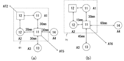
図4は実施例2で解決する問題点を説明するための光源プローブと受光プローブの配置例を示す図である。図5は実施例2を説明するための光源プローブと受光プローブの配置例を示す図である。 FIG. 4 is a diagram illustrating an arrangement example of a light source probe and a light receiving probe for explaining a problem to be solved in the second embodiment. FIG. 5 is a diagram illustrating an arrangement example of a light source probe and a light receiving probe for explaining the second embodiment.
[実施例2の問題提起]
各光源プローブと受光プローブ距離の演算の手法は実施例1で説明したとおりであるが、例えば、図4(a)に対して図4(b)に示すように、第12チャンネルの光源プローブと第14チャンネルの光源プローブが入れ替わっているかいないかの配置の区別はできない。
そこで、配置の区別ができるようにするため、複数の受信プローブを用いる。
[Proposed problem of Example 2]
The method of calculating the distance between each light source probe and the light receiving probe is as described in the first embodiment.For example, as shown in FIG. 4 (b) with respect to FIG. The arrangement of whether the 14th channel light source probe is switched or not cannot be distinguished.
Therefore, a plurality of receiving probes are used so that the arrangement can be distinguished.
[実施例2の生体光計測装置の動作]
図5(a)において、光源プローブと受光プローブの間の光減衰量がほぼ同じと仮定した場合、第11及び12チャンネルの受光プローブで検出される信号強度AT5および信号強度AT6は第11乃至14チャンネルの光源プローブに由来する信号強度A1〜A4の合計となる。基準の光源プローブとして第11チャンネルの光源プローブと第11チャンネルの受信プローブの距離が30mmであると与えられているものとする。
[Operation of the biological optical measurement device of Example 2]
In FIG. 5 (a), when it is assumed that the light attenuation amount between the light source probe and the light receiving probe is substantially the same, the signal intensity AT5 and the signal intensity AT6 detected by the 11th and 12th channel light receiving probes are 11th to 14th. This is the sum of signal intensities A1 to A4 derived from the channel light source probes. Assume that the distance between the eleventh channel light source probe and the eleventh channel reception probe is 30 mm as the reference light source probe.
第12チャンネルの受光プローブに関しては、第11及び第12チャンネルの光源プローブは距離30mmであるが、第13及び第14チャンネルの光源プローブは約80mmとなる。この場合30mmの時の信号強度に対して、約200分の1の強度となりほぼゼロとみなすことができる。 Regarding the light receiving probe of the twelfth channel, the light source probes of the eleventh and twelfth channels are 30 mm in distance, while the light source probes of the thirteenth and fourteenth channels are about 80 mm. In this case, the signal intensity at 30 mm is about 1 / 200th of the signal intensity and can be regarded as almost zero.
AT5=A1+A2+A3+A4≒A1+A2・・・(4)
※A3,A4由来の信号強度はほぼゼロである。
AT5 = A1 + A2 + A3 + A4 ≒ A1 + A2 ... (4)
* Signal intensity derived from A3 and A4 is almost zero.
上記より、第13及び14チャンネルの光源プローブの位置関係は推定のままで未確定であるが、第11及び12チャンネルの受光プローブおよび第11及び12チャンネルの受光プローブの位置関係61は確定する。 From the above, the positional relationship between the 13th and 14th channel light source probes is still unestablished, but the positional relationship 61 between the 11th and 12th channel light receiving probes and the 11th and 12th channel light receiving probes is determined.
次に図5(b)において距離が異なる場合に、複数の受光プローブを配置した場合を示す。基準プローブとして第11チャンネルの光源プローブと第11チャンネルの受光プローブの距離が30mmであると与えられているものとする。 Next, FIG. 5 (b) shows a case where a plurality of light receiving probes are arranged when the distances are different. It is assumed that the distance between the 11th channel light source probe and the 11th channel light receiving probe is 30 mm as a reference probe.
AT6=A1(第11チャンネルの光源プローブ)
+8.7×A1(第12チャンネルの光源プローブ)
+0.16×A1(第13チャンネルの光源プローブ)
+0.005×A1(第14チャンネルの光源プローブ)・・・(5)
第13及び14チャンネルの光源プローブに関する信号強度はほぼゼロとみなすことができる。第11チャンネルの光源プローブは基準位置として第11チャンネルの受光プローブとの距離が30mmとわかっているため、第12チャンネルの光源プローブに由来する信号強度が第11チャンネルの光源プローブに由来する信号強度に比べ8.7倍大きいということは、その距離は15mmと推定可能である。
AT6 = A1 (11th channel light source probe)
+8.7 x A1 (12th channel light source probe)
+ 0.16 × A1 (13th channel light source probe)
+0.005 x A1 (14th channel light source probe) (5)
The signal strength for the thirteenth and fourteenth channel light source probes can be considered to be almost zero. Since the 11th channel light source probe is known to have a distance of 30 mm from the 11th channel light receiving probe as a reference position, the signal intensity derived from the 12th channel light source probe is the signal strength derived from the 11th channel light source probe. It is estimated that the distance is 15 mm, which is 8.7 times larger than.
同様の処理を第12チャンネルの受光プローブにも行うことで、第13及び14チャンネルの光源プローブの位置関係は推定のままで未確定であるが、第11及び12チャンネルの光源プローブおよび第11及び第12チャンネルの受光プローブの位置関係71は確定する。
By performing the same processing for the light receiving probe of the 12th channel, the positional relationship of the light source probes of the 13th and 14th channels is uncertain as estimated, but the light source probes of the 11th and 12th channels and the 11th and 12th light source probes The
AT6=A1+A2+A3+A4≒A1+A2≒A1+8.7×A1・・・(6)
※A3,A4由来の信号強度はほぼゼロである。
AT6 = A1 + A2 + A3 + A4 ≒ A1 + A2 ≒ A1 + 8.7 × A1 ... (6)
* Signal intensity derived from A3 and A4 is almost zero.
以上、基本的なプローブの位置関係の推定であり、あとは複数の光源プローブ及び受光プローブを配置すれば、より多くの信号強度の情報が得られるため、各プローブの位置関係を推定してもよい。 The above is the basic estimation of the positional relationship of the probes. After that, if a plurality of light source probes and light receiving probes are arranged, more signal intensity information can be obtained. Good.
また、光源プローブに対して受光プローブを指定したら、初期チャンネル(第11チャンネル)から制御部14がカウンタ値を有して、受光プローブを指定するごとにカウントを加算していけば、受光プローブの番号をカウンタ値で割り付けることができる。つまり、前記受光プローブの指定回数からチャンネル番号を設定することができる。
If a light receiving probe is designated for the light source probe, the
またプローブの位置関係の左右及び上下の、いわゆる鏡状配置に関しては推定が難しい場合があるため、その場合も考慮して、基準プローブの設定には、例えば図中、左上に第11チャンネルの光源プローブと受信プローブを配置するようにし、それを基準位置のプローブとして、絶対的な位置関係を推定する。 In addition, since it may be difficult to estimate the so-called mirror-like arrangement of right and left and up and down of the positional relationship of the probe, in consideration of such cases, for example, the light source of the eleventh channel is set at the upper left in the figure. A probe and a receiving probe are arranged, and the absolute positional relationship is estimated with the probe as a reference position probe.
[実施例2の生体光計測装置の効果]
以上説明したように実施例2の生体光計測装置は、実施例1で説明した効果の他に、複数の受光プローブを複数有することによって、光源プローブと受光プローブ間の配置の測定あるいは入力の煩雑さを解消することが可能となるという実施例2の特有の効果を奏する。
[Effects of the biological optical measurement device of Example 2]
As described above, the living body light measurement apparatus according to the second embodiment has a plurality of light receiving probes in addition to the effects described in the first embodiment, thereby making it difficult to measure or input the arrangement between the light source probes and the light receiving probes. There is an effect peculiar to the second embodiment that it is possible to eliminate this problem.
また、実施例1、2では、各光源プローブを個別に選択的に発光させて、受光プローブと一対一になるような説明であったが、関係する光源プローブを同時に発光させ、受光プローブで同時受信し、各光源プローブに対応した信号に分離する手法もある。これらの分離する手法には、一般的にロックインアンプ技術が知られているが、その他の類似した方法であってもよい。 Further, in the first and second embodiments, each light source probe is individually selectively emitted to have a one-to-one relationship with the light receiving probe. However, the related light source probes are simultaneously emitted and simultaneously received by the light receiving probe. There is also a method of receiving and separating the signal corresponding to each light source probe. A lock-in amplifier technique is generally known as the separation method, but other similar methods may be used.
また上記の実施例1、2の手法で想定した各プローブの位置関係は、あくまで推定であるため、最終的には推定結果を例えば表示部36に表示し、実際に検者が目にし、手動で容易に変更できるようにしてもよい。
In addition, since the positional relationship of each probe assumed in the methods of Examples 1 and 2 above is only an estimation, the estimation result is finally displayed on, for example, the
100 光源部、120 光計測部、140 制御部、16 半導体レーザ、18 光モジュール、20 光ファイバ、22 被検体、26 検出用光ファイバ、28 光電変換素子、30 ロックインアンプ、32 A/D変換器、34 信号処理部、36 表示部、38 記憶部、40 入出力部 100 Light source unit, 120 Optical measurement unit, 140 Control unit, 16 Semiconductor laser, 18 Optical module, 20 Optical fiber, 22 Subject, 26 Optical fiber for detection, 28 Photoelectric conversion element, 30 Lock-in amplifier, 32 A / D conversion Unit, 34 Signal processing unit, 36 Display unit, 38 Storage unit, 40 Input / output unit
Claims (3)
Priority Applications (1)
| Application Number | Priority Date | Filing Date | Title |
|---|---|---|---|
| JP2014026092A JP2015150186A (en) | 2014-02-14 | 2014-02-14 | Biophotonic measurement apparatus |
Applications Claiming Priority (1)
| Application Number | Priority Date | Filing Date | Title |
|---|---|---|---|
| JP2014026092A JP2015150186A (en) | 2014-02-14 | 2014-02-14 | Biophotonic measurement apparatus |
Publications (2)
| Publication Number | Publication Date |
|---|---|
| JP2015150186A true JP2015150186A (en) | 2015-08-24 |
| JP2015150186A5 JP2015150186A5 (en) | 2017-03-02 |
Family
ID=53893078
Family Applications (1)
| Application Number | Title | Priority Date | Filing Date |
|---|---|---|---|
| JP2014026092A Pending JP2015150186A (en) | 2014-02-14 | 2014-02-14 | Biophotonic measurement apparatus |
Country Status (1)
| Country | Link |
|---|---|
| JP (1) | JP2015150186A (en) |
Cited By (3)
| Publication number | Priority date | Publication date | Assignee | Title |
|---|---|---|---|---|
| WO2018181953A1 (en) * | 2017-03-31 | 2018-10-04 | 国立大学法人九州大学 | Hemoglobin quantification device, hemoglobin quantification method, hemoglobin quantification program, and surgical assistance device |
| CN114305329A (en) * | 2021-11-23 | 2022-04-12 | 西安电子科技大学 | Diffusion optical tomography data acquisition and self-correction method |
| CN114305329B (en) * | 2021-11-23 | 2024-04-26 | 西安电子科技大学 | Diffusion optical tomography data acquisition and self-correction method |
Citations (6)
| Publication number | Priority date | Publication date | Assignee | Title |
|---|---|---|---|---|
| JPH0779935A (en) * | 1993-09-20 | 1995-03-28 | Shimadzu Corp | Brain function analyser |
| JP2001133396A (en) * | 1999-11-08 | 2001-05-18 | Natl Inst Of Advanced Industrial Science & Technology Meti | Light measuring device |
| JP2005118594A (en) * | 2004-12-16 | 2005-05-12 | Hitachi Ltd | Light measuring device |
| JP2006218196A (en) * | 2005-02-14 | 2006-08-24 | Hitachi Medical Corp | Biological light measuring device |
| JP2010104586A (en) * | 2008-10-30 | 2010-05-13 | Hitachi Medical Corp | Optical measuring apparatus for living body and method of estimating measurement noise |
| JP2012125370A (en) * | 2010-12-15 | 2012-07-05 | Hitachi Ltd | Biological measurement apparatus |
-
2014
- 2014-02-14 JP JP2014026092A patent/JP2015150186A/en active Pending
Patent Citations (6)
| Publication number | Priority date | Publication date | Assignee | Title |
|---|---|---|---|---|
| JPH0779935A (en) * | 1993-09-20 | 1995-03-28 | Shimadzu Corp | Brain function analyser |
| JP2001133396A (en) * | 1999-11-08 | 2001-05-18 | Natl Inst Of Advanced Industrial Science & Technology Meti | Light measuring device |
| JP2005118594A (en) * | 2004-12-16 | 2005-05-12 | Hitachi Ltd | Light measuring device |
| JP2006218196A (en) * | 2005-02-14 | 2006-08-24 | Hitachi Medical Corp | Biological light measuring device |
| JP2010104586A (en) * | 2008-10-30 | 2010-05-13 | Hitachi Medical Corp | Optical measuring apparatus for living body and method of estimating measurement noise |
| JP2012125370A (en) * | 2010-12-15 | 2012-07-05 | Hitachi Ltd | Biological measurement apparatus |
Cited By (6)
| Publication number | Priority date | Publication date | Assignee | Title |
|---|---|---|---|---|
| WO2018181953A1 (en) * | 2017-03-31 | 2018-10-04 | 国立大学法人九州大学 | Hemoglobin quantification device, hemoglobin quantification method, hemoglobin quantification program, and surgical assistance device |
| JPWO2018181953A1 (en) * | 2017-03-31 | 2020-04-30 | 株式会社シーアイラボ | Hemoglobin quantification device, hemoglobin quantification method and hemoglobin quantification program, and treatment support device |
| US11344233B2 (en) | 2017-03-31 | 2022-05-31 | Tetsuo Ikeda | Hemoglobin quantification device, hemoglobin quantification method, hemoglobin quantification program, and surgical assistance device |
| JP7131831B2 (en) | 2017-03-31 | 2022-09-06 | 哲夫 池田 | Hemoglobin quantification device, hemoglobin quantification method, hemoglobin quantification program, and treatment support device |
| CN114305329A (en) * | 2021-11-23 | 2022-04-12 | 西安电子科技大学 | Diffusion optical tomography data acquisition and self-correction method |
| CN114305329B (en) * | 2021-11-23 | 2024-04-26 | 西安电子科技大学 | Diffusion optical tomography data acquisition and self-correction method |
Similar Documents
| Publication | Publication Date | Title |
|---|---|---|
| EP1327418B1 (en) | Organism optical measurement instrument | |
| KR20150094196A (en) | apparatus for evaluating skin condition and method of evaluating skin condition using the same | |
| JP2013523362A (en) | Apparatus and method for determining biological, chemical and / or physiological parameters in biological tissue | |
| JP2002095652A (en) | Device of measuring concentration of light-absorbing material in blood | |
| US10299710B2 (en) | Organism optical measurement device | |
| KR101385786B1 (en) | Measuring system and measuring method, in particular for determining blood glucose | |
| JP2012237595A (en) | Optical tomography device | |
| JP5686738B2 (en) | Biological light measurement device | |
| RU2014142631A (en) | PHOTON NEEDLE SYSTEM WITH MEASUREMENT INTEGRATION TIMES DEPENDING ON THE NEEDLE DISPLACEMENT SPEED | |
| JP2014202752A (en) | Improved analyte meter and method of operation | |
| CN104603598A (en) | Analysis apparatus | |
| EP3605065A1 (en) | Apparatus and method for analyzing component of object | |
| JP5686739B2 (en) | Inspection device with magnetic position detector, magnetic field measurement tool, magnetic field detection program | |
| JP6358573B2 (en) | Operation method of breast measurement apparatus and breast measurement apparatus | |
| JP2015150186A (en) | Biophotonic measurement apparatus | |
| JP2015150186A5 (en) | ||
| US20140296719A1 (en) | Biometric device, biometric method, program, and recording medium | |
| KR20180045735A (en) | Wearable device, and method for health monitoring | |
| CN104237321A (en) | orientation independent meter | |
| WO2015194162A1 (en) | Measurement device and measurement method | |
| JP5210733B2 (en) | Biological light measuring device having stimulation presentation function and stimulation task presentation method | |
| KR102522203B1 (en) | Apparatus and method for measuring bio-information | |
| JP2016106660A (en) | Biological information acquisition device and biological information acquisition method | |
| US9964485B2 (en) | Optical device and method for determining an optical property of specimen | |
| WO2018182535A1 (en) | System for optical measurements and operation method |
Legal Events
| Date | Code | Title | Description |
|---|---|---|---|
| A711 | Notification of change in applicant |
Free format text: JAPANESE INTERMEDIATE CODE: A712 Effective date: 20160427 |
|
| A521 | Request for written amendment filed |
Free format text: JAPANESE INTERMEDIATE CODE: A523 Effective date: 20170126 |
|
| A621 | Written request for application examination |
Free format text: JAPANESE INTERMEDIATE CODE: A621 Effective date: 20170126 |
|
| A977 | Report on retrieval |
Free format text: JAPANESE INTERMEDIATE CODE: A971007 Effective date: 20170828 |
|
| A131 | Notification of reasons for refusal |
Free format text: JAPANESE INTERMEDIATE CODE: A131 Effective date: 20170905 |
|
| A02 | Decision of refusal |
Free format text: JAPANESE INTERMEDIATE CODE: A02 Effective date: 20180227 |