JP4490199B2 - Active vibration isolator - Google Patents
Active vibration isolator Download PDFInfo
- Publication number
- JP4490199B2 JP4490199B2 JP2004222905A JP2004222905A JP4490199B2 JP 4490199 B2 JP4490199 B2 JP 4490199B2 JP 2004222905 A JP2004222905 A JP 2004222905A JP 2004222905 A JP2004222905 A JP 2004222905A JP 4490199 B2 JP4490199 B2 JP 4490199B2
- Authority
- JP
- Japan
- Prior art keywords
- signal
- frequency
- control signal
- side switch
- low
- Prior art date
- Legal status (The legal status is an assumption and is not a legal conclusion. Google has not performed a legal analysis and makes no representation as to the accuracy of the status listed.)
- Expired - Lifetime
Links
- 230000003044 adaptive effect Effects 0.000 claims description 62
- 230000000737 periodic effect Effects 0.000 claims description 27
- 230000005284 excitation Effects 0.000 claims description 13
- 125000004122 cyclic group Chemical group 0.000 claims description 3
- 238000013016 damping Methods 0.000 claims 2
- 238000010586 diagram Methods 0.000 description 18
- 230000001133 acceleration Effects 0.000 description 16
- 238000004364 calculation method Methods 0.000 description 11
- 238000000034 method Methods 0.000 description 7
- 230000004043 responsiveness Effects 0.000 description 7
- 230000002159 abnormal effect Effects 0.000 description 6
- 230000007423 decrease Effects 0.000 description 6
- 230000002194 synthesizing effect Effects 0.000 description 6
- 238000013500 data storage Methods 0.000 description 4
- 230000000694 effects Effects 0.000 description 4
- 230000005540 biological transmission Effects 0.000 description 3
- 230000007274 generation of a signal involved in cell-cell signaling Effects 0.000 description 2
- 230000001629 suppression Effects 0.000 description 2
- 230000007935 neutral effect Effects 0.000 description 1
- 230000002093 peripheral effect Effects 0.000 description 1
- 230000010363 phase shift Effects 0.000 description 1
- 238000010992 reflux Methods 0.000 description 1
- 230000001172 regenerating effect Effects 0.000 description 1
- 230000008929 regeneration Effects 0.000 description 1
- 238000011069 regeneration method Methods 0.000 description 1
Images


Classifications
-
- F—MECHANICAL ENGINEERING; LIGHTING; HEATING; WEAPONS; BLASTING
- F16—ENGINEERING ELEMENTS AND UNITS; GENERAL MEASURES FOR PRODUCING AND MAINTAINING EFFECTIVE FUNCTIONING OF MACHINES OR INSTALLATIONS; THERMAL INSULATION IN GENERAL
- F16F—SPRINGS; SHOCK-ABSORBERS; MEANS FOR DAMPING VIBRATION
- F16F15/00—Suppression of vibrations in systems; Means or arrangements for avoiding or reducing out-of-balance forces, e.g. due to motion
- F16F15/02—Suppression of vibrations of non-rotating, e.g. reciprocating systems; Suppression of vibrations of rotating systems by use of members not moving with the rotating systems
Landscapes
- Engineering & Computer Science (AREA)
- General Engineering & Computer Science (AREA)
- Physics & Mathematics (AREA)
- Acoustics & Sound (AREA)
- Aviation & Aerospace Engineering (AREA)
- Mechanical Engineering (AREA)
- Vibration Prevention Devices (AREA)
- Arrangement Or Mounting Of Propulsion Units For Vehicles (AREA)
- Apparatuses For Generation Of Mechanical Vibrations (AREA)
Description
本発明は、能動型防振装置、特に車両のエンジン等の振動発生源から発生する振動を能動的に抑制する能動型防振装置に関するものである。 The present invention relates to an active vibration isolator, and more particularly to an active vibration isolator that actively suppresses vibration generated from a vibration generation source such as a vehicle engine.
電磁石を備えた能動型防振装置が、例えば特許文献1に開示されている。当該電磁石は、いわゆるエンジンマウントの内部に配置されており、電磁石が発生する加振力によりエンジンの振動の伝達を抑制している。具体的には、エンジンの振動に応じて電磁石の通電状態を制御することにより行っている。
しかし、従来の能動型防振装置においては電磁石への通電状態がオン状態からオフ状態になる際に、異音が生じる場合があった。 However, in the conventional active vibration isolator, abnormal noise may occur when the energization state of the electromagnet changes from the on state to the off state.
本発明は、このような事情に鑑みて為されたものであり、例えば電磁石等の電磁アクチュエータへの通電状態がオフ状態となることを抑制することにより、異音の発生を抑制することができる能動型防振装置を提供することを目的とする。 The present invention has been made in view of such circumstances, and for example, by suppressing the energization state of an electromagnetic actuator such as an electromagnet from being turned off, generation of abnormal noise can be suppressed. An object is to provide an active vibration isolator.
本発明の能動型防振装置は、電流通電量を可変にすることにより加振力を発生する電磁アクチュエータと、車両の振動発生源から出力される周期性のパルス信号に基づき車両特定部位の振動を能動的に抑制させる周期性制御信号を発生する制御信号発生手段と、前記周期性制御信号に基づき前記電磁アクチュエータへの前記電流通電量を可変にして前記電磁アクチュエータを駆動する駆動手段とを備える。 The active vibration isolator of the present invention includes an electromagnetic actuator that generates an excitation force by varying the amount of current flow, and a vibration of a specific part of the vehicle based on a periodic pulse signal output from a vibration source of the vehicle. Control signal generating means for generating a periodic control signal for actively suppressing the current, and drive means for driving the electromagnetic actuator by varying the amount of current applied to the electromagnetic actuator based on the periodic control signal. .
そして、本発明の能動型防振装置の特徴的構成は、前記駆動手段が、非対称型ハーフブリッジ回路と駆動信号出力手段を有することである。ここで、前記非対称型ハーフブリッジ回路は、少なくとも前記電磁アクチュエータの正極側に接続されたハイサイドスイッチと、前記電磁アクチュエータの負極側に接続され該ハイサイドスイッチに対して非対称位置に配置されたローサイドスイッチとを有する回路である。例えば、Hブリッジ回路であって、一方のアームの上側にハイサイドスイッチを配置し、他方のアームの下側にローサイドスイッチを配置した回路である。なお、逆流(回生)するときのみ電流が流れるように、一方のアームの下側及び他方のアームの上側にはダイオード等を配置する。そして、ハイサイドスイッチ及びローサイドスイッチがオンオフ駆動することにより、電磁アクチュエータに電流が流れる。 And the characteristic structure of the active vibration isolator of the present invention is that the drive means has an asymmetric half-bridge circuit and drive signal output means. Here, the asymmetric half-bridge circuit includes at least a high-side switch connected to the positive electrode side of the electromagnetic actuator and a low-side electrode connected to the negative electrode side of the electromagnetic actuator and disposed at an asymmetric position with respect to the high-side switch. A circuit having a switch. For example, an H bridge circuit is a circuit in which a high side switch is arranged above one arm and a low side switch is arranged below the other arm. It should be noted that a diode or the like is disposed on the lower side of one arm and the upper side of the other arm so that a current flows only during reverse flow (regeneration). Then, when the high-side switch and the low-side switch are turned on / off, a current flows through the electromagnetic actuator.
そして、前記駆動信号出力手段は、前記周期性制御信号が正の場合と負の場合とで異なる駆動信号を出力する。具体的には、前記周期性制御信号が正の場合には、前記駆動信号出力手段は、前記ハイサイドスイッチ及び前記ローサイドスイッチのうち何れか一方にオン駆動信号を出力し、他方に前記周期性制御信号に基づきPWM駆動信号を出力する。若しくは、前記周期性制御信号が正の場合に、前記駆動信号出力手段は、前記ハイサイドスイッチ及び前記ローサイドスイッチの何れもに前記周期性制御信号に基づきPWM駆動信号を出力する。一方、前記周期性制御信号が負の場合には、前記駆動信号出力手段は、前記ハイサイドスイッチ及び前記ローサイドスイッチのうち何れか一方にオフ駆動信号を出力し、他方に前記周期性制御信号に基づきPWM駆動信号を出力する。 The drive signal output means outputs different drive signals depending on whether the periodicity control signal is positive or negative. Specifically, when the periodicity control signal is positive, the drive signal output means outputs an ON drive signal to one of the high-side switch and the low-side switch and the periodicity to the other. A PWM drive signal is output based on the control signal. Alternatively, when the periodic control signal is positive, the drive signal output means outputs a PWM drive signal to both the high-side switch and the low-side switch based on the periodic control signal. On the other hand, when the periodic control signal is negative, the drive signal output means outputs an off drive signal to one of the high-side switch and the low-side switch, and the other to the periodic control signal. Based on this, a PWM drive signal is output.
つまり、前記駆動信号出力手段は、前記周期性制御信号が正の場合に、電磁アクチュエータに流れる電流は増加するように作用する。一方、前記駆動信号出力手段は、前記周期性制御信号が負の場合に、電磁アクチュエータに流れる電流は減少するように作用する。 That is, the drive signal output means acts so that the current flowing through the electromagnetic actuator increases when the periodicity control signal is positive. On the other hand, the drive signal output means acts so that the current flowing through the electromagnetic actuator decreases when the periodicity control signal is negative.
本発明によれば、周期性制御信号が負の場合に、ハイサイドスイッチ及びローサイドスイッチのうち何れか一方をオフ駆動させ、他方を周期性制御信号に基づきPWM駆動させている。ハイサイドスイッチ及びローサイドスイッチを共にオフ駆動させると、急激に電磁アクチュエータに流れる電流が減少して、電流値が零になる場合がある。しかし、本発明のように、ハイサイドスイッチ及びローサイドスイッチのうち何れか一方をオフ駆動させ、他方をPWM駆動させることにより、電磁アクチュエータに流れる電流の減少率が小さくなる。従って、電磁アクチュエータに流れる電流値が零にならないように、電磁アクチュエータを制御することができる。これにより、電磁アクチュエータ(電磁石等)の通電状態がオン状態からオフ状態になることを抑制することにより、結果として異音の発生を抑制することができる。 According to the present invention, when the periodic control signal is negative, one of the high-side switch and the low-side switch is driven off, and the other is PWM-driven based on the periodic control signal. When both the high-side switch and the low-side switch are driven off, the current flowing through the electromagnetic actuator may suddenly decrease and the current value may become zero. However, as in the present invention, when either one of the high-side switch and the low-side switch is driven off and the other is PWM-driven, the reduction rate of the current flowing through the electromagnetic actuator is reduced. Therefore, the electromagnetic actuator can be controlled so that the value of the current flowing through the electromagnetic actuator does not become zero. Thereby, by suppressing the energized state of the electromagnetic actuator (such as an electromagnet) from being turned on to being turned off, it is possible to suppress the occurrence of abnormal noise as a result.
次に、実施形態を挙げ、本発明をより詳しく説明する。上述したように、本発明の能動型防振装置は、電磁アクチュエータと、制御信号発生手段と、駆動手段とを備える。 Next, the present invention will be described in more detail with reference to embodiments. As described above, the active vibration isolator of the present invention includes an electromagnetic actuator , a control signal generating unit, and a driving unit.
(1)周期性制御信号
ここで、制御信号発生手段により発生される周期性制御信号は、前記パルス信号の周波数が所定周波数以下の場合と、所定周波数より大きい場合とにおいて、異なるようにすることが好ましい。すなわち、周期性制御信号は、前記パルス信号の周波数が所定周波数以下の場合には前記パルス信号の周波数の1次周波数成分信号と前記パルス信号の周波数に対する高次周波数成分信号とを合わせた低周波数制御信号であり、前記パルス信号の周波数が前記所定周波数より大きい場合には前記1次周波数成分信号のみからなる高周波数制御信号であるとすることが好ましい。
(1) Periodic control signal Here, the periodic control signal generated by the control signal generating means is made different depending on whether the frequency of the pulse signal is lower than a predetermined frequency or higher than the predetermined frequency. Is preferred. That is, when the frequency of the pulse signal is equal to or lower than a predetermined frequency, the periodicity control signal is a low frequency obtained by combining a primary frequency component signal of the pulse signal frequency and a high-order frequency component signal with respect to the frequency of the pulse signal. a control signal, it is preferable that the frequency of the pulse signal is a is greater than the predetermined frequency is a high frequency control signal consisting of only the primary frequency component signal.
ここで、振動発生源がエンジンであって、本発明の能動型防振装置をエンジンによる振動の抑制に適用する場合を例に挙げて説明する。本発明の能動型防振装置をエンジンによる振動の1次周波数成分のみに適用した場合であっても、振動発生源であるエンジンによる振動の高次周波数とエンジンフレームの固有振動数とが一致する場合には、両者が共振を起こすることによりエンジンフレームの振動が大きくなるおそれがある。そこで、周期性制御信号が、エンジンによる振動の1次周波数成分のみならず、高次周波数成分に対しても考慮することが好ましい。つまり、周期性制御信号が高次周波数成分に対して考慮されることにより、エンジンの振動の高次周波数成分を抑制することができる。これにより、エンジンの振動の高次周波数とエンジンフレームの固有振動数とが一致した場合であっても、エンジンフレームの振動を抑制することができる。ただし、エンジンによる振動の1次周波数がエンジンフレームの固有振動数より大きくなると、両者が共振することはない。従って、上記の場合には、低周波数制御信号と高周波数制御信号とが切り替えられる所定周波数が、パルス信号の周波数の2次周波数がエンジンフレームの固有振動数より大きくなる前記パルス信号の周波数とすればよい。すなわち、例えば、エンジンフレームの固有振動数が100Hzの場合には、所定周波数は50Hzより大きくすればよい。 Here, a case where the vibration generation source is an engine and the active vibration isolator of the present invention is applied to suppression of vibration by the engine will be described as an example. Even when the active vibration isolator of the present invention is applied only to the primary frequency component of the vibration caused by the engine, the high-order frequency of the vibration caused by the engine that is the vibration source matches the natural frequency of the engine frame. In some cases, the vibration of the engine frame may increase due to resonance between the two. Therefore, it is preferable that the periodicity control signal consider not only the primary frequency component of the vibration caused by the engine but also the high-order frequency component. That is, the high-order frequency component of engine vibration can be suppressed by considering the periodic control signal with respect to the high-order frequency component. Thereby, even if it is a case where the higher order frequency of an engine vibration and the natural frequency of an engine frame correspond, vibration of an engine frame can be controlled. However, if the primary frequency of the vibration caused by the engine becomes higher than the natural frequency of the engine frame, they will not resonate. Therefore, in the above case, the predetermined frequency at which the low frequency control signal and the high frequency control signal are switched is the frequency of the pulse signal at which the secondary frequency of the pulse signal is greater than the natural frequency of the engine frame. That's fine. That is, for example, when the natural frequency of the engine frame is 100 Hz, the predetermined frequency may be greater than 50 Hz.
また、前記低周波数制御信号の前記1次周波数成分信号は、正弦波信号としてもよい。つまり、正弦波信号である低周波数数制御信号の1次周波数成分信号は、実際のエンジン等の振動の1次周波数成分とほぼ同様の波形となる。これにより、エンジン等の振動発生源から生じる振動をより適切に抑制することができ、結果として非常に高い静粛性を得ることができる。 The primary frequency component signal of the low frequency control signal may be a sine wave signal. That is, the primary frequency component signal of the low frequency number control signal, which is a sine wave signal, has a waveform that is substantially the same as the primary frequency component of vibration of an actual engine or the like. Thereby, the vibration which arises from vibration sources, such as an engine, can be suppressed more appropriately, and as a result, very high silence can be obtained.
また、前記低周波数制御信号の前記1次周波数成分信号は、正弦波信号に基づき算出された矩形波信号としてもよい。1次周波数成分信号を矩形波信号とすることにより、1次周波数成分の振動抑制力を高めることができる。さらに、1次周波数成分信号を矩形波信号とすることにより、応答性を高めることができる。つまり、応答性の低い電磁アクチュエータを使用する場合であっても、確実にエンジン等の振動発生源から生じる振動を抑制することができる。 The primary frequency component signal of the low frequency control signal may be a rectangular wave signal calculated based on a sine wave signal. By making the primary frequency component signal a rectangular wave signal, the vibration suppression force of the primary frequency component can be increased. Furthermore, the responsiveness can be enhanced by making the primary frequency component signal a rectangular wave signal. That is, even when an electromagnetic actuator with low responsiveness is used, it is possible to reliably suppress vibration generated from a vibration generating source such as an engine.
また、前記高周波数制御信号は、前記1次周波数成分信号に基づき算出された矩形波信号としてもよい。エンジン等の振動発生源により生じる振動の周波数が高い領域においては、電磁アクチュエータの高い応答性が要求される。そこで、高周波数制御信号を矩形波信号とすることにより応答性を高めることができるので、確実に高周波数領域における振動を抑制することができる。 The high frequency control signal may be a rectangular wave signal calculated based on the primary frequency component signal. In a region where the frequency of vibration generated by a vibration generation source such as an engine is high, high responsiveness of the electromagnetic actuator is required. Therefore, since the responsiveness can be enhanced by making the high frequency control signal a rectangular wave signal, vibration in the high frequency region can be reliably suppressed.
(2)駆動信号出力手段
駆動信号出力手段は、上述したように、前記周期性制御信号が正の場合と負の場合とにより非対称型ハーフブリッジの各スイッチの駆動を異なるようにしている。ここで、駆動信号出力手段は、さらに、前記周期性制御信号が負の際に、前記パルス信号の周波数が所定周波数以下の場合と所定周波数より大きい場合とにより非対称型ハーフブリッジの各スイッチの駆動を異なるようにしてもよい。
(2) Drive signal output means As described above, the drive signal output means makes the drive of each switch of the asymmetric half bridge different depending on whether the periodicity control signal is positive or negative. Here, the drive signal output means further drives each switch of the asymmetrical half bridge when the periodicity control signal is negative depending on whether the frequency of the pulse signal is lower than a predetermined frequency or higher than the predetermined frequency. May be different.
具体的には、前記駆動信号出力手段は、前記周期性制御信号が負であって前記パルス信号の周波数が所定周波数以下の場合に、前記ハイサイドスイッチ及び前記ローサイドスイッチのうち何れか一方にオフ駆動信号を出力し、他方に前記周期性制御信号に基づきPWM駆動信号を出力する。一方、前記駆動信号出力手段は、前記周期性制御信号が負であって前記パルス信号の周波数が前記所定周波数より大きい場合に、前記ハイサイドスイッチ及び前記ローサイドスイッチにオフ駆動信号を出力する。 Specifically, the drive signal output means turns off either the high-side switch or the low-side switch when the periodic control signal is negative and the frequency of the pulse signal is equal to or lower than a predetermined frequency. A drive signal is output, and a PWM drive signal is output to the other based on the periodicity control signal . Meanwhile, the drive signal output means, the frequency of the pulse signal the cyclic control signal is negative is larger than the predetermined frequency, and outputs an OFF driving signal to the high-side switch and the low-side switch.
つまり、周期性制御信号が負の場合には、パルス信号の周波数が所定周波数以下の場合にのみ、各スイッチの何れか一方をオフ駆動させ他方をPWM駆動させている。このように各スイッチの何れか一方をオフ駆動させ、他方をPWM駆動させることにより、電磁アクチュエータに流れる電流の減少率が小さくなる。従って、電磁アクチュエータに流れる電流値が零にならないように、電磁アクチュエータを制御することができる。これにより、パルス信号の周波数が所定周波数以下の場合には、電磁アクチュエータ(電磁石等)の通電状態がオン状態からオフ状態になることを抑制でき、結果として異音の発生を抑制することができる。 That is, when the periodicity control signal is negative, only one of the switches is driven off and the other is PWM driven only when the frequency of the pulse signal is equal to or lower than the predetermined frequency. As described above, when one of the switches is driven off and the other is driven by PWM, the reduction rate of the current flowing through the electromagnetic actuator is reduced. Therefore, the electromagnetic actuator can be controlled so that the value of the current flowing through the electromagnetic actuator does not become zero. Thereby, when the frequency of a pulse signal is below a predetermined frequency, it can control that the energization state of an electromagnetic actuator (electromagnet etc.) changes from an ON state to an OFF state, and can suppress generation of abnormal noise as a result. .
一方、パルス信号の周波数が所定周波数より大きい場合には、何れのスイッチもオフ駆動させている。パルス信号の周波数が大きくなるにつれて、エンジン等による騒音が大きくなる。そのため、パルス信号の周波数が大きい場合には、電磁アクチュエータの通電状態がオン状態からオフ状態になる際に生じる異音は、それほど問題とならない。そこで、パルス信号の周波数が所定周波数より大きい場合には、何れのスイッチもオフ駆動させることにより、制御の容易化を図っている。 On the other hand, when the frequency of the pulse signal is higher than the predetermined frequency, all the switches are driven off. As the frequency of the pulse signal increases, noise from the engine or the like increases. For this reason, when the frequency of the pulse signal is large, the noise generated when the energization state of the electromagnetic actuator changes from the on state to the off state is not a problem. Therefore, when the frequency of the pulse signal is higher than the predetermined frequency, the control is facilitated by driving any switch off.
(3)制御信号発生手段
制御信号発生手段は、上述したように、パルス信号に基づき車両特定部位の振動を能動的に抑制させる周期性制御信号を発生する。この制御信号発生手段は、前記パルス信号の周波数が所定周波数以下の場合と前記所定周波数より大きい場合とにより異なるようにしてもよい。
(3) Control signal generating means As described above, the control signal generating means generates a periodic control signal that actively suppresses vibration of the vehicle specific part based on the pulse signal . The control signal generating means, the frequency of the pulse signal may be different depending on the case greater than said predetermined frequency in the case of less than the predetermined frequency.
すなわち、前記制御信号発生手段は、前記パルス信号の周波数が所定周波数以下の場合には、予め記憶されたデータマップ及び制御時の運転状態に基づき前記周期性制御信号を算出するようにする。一方、前記制御信号発生手段は、前記パルス信号の周波数が所定周波数より大きい場合には、適応制御法に基づき前記周期性制御信号を算出するようにする。 That is, when the frequency of the pulse signal is equal to or lower than the predetermined frequency, the control signal generating means calculates the periodic control signal based on a data map stored in advance and an operating state at the time of control. On the other hand, when the frequency of the pulse signal is higher than a predetermined frequency, the control signal generating means calculates the periodic control signal based on an adaptive control method.
これにより、パルス信号の周波数が所定周波数以下の場合には、データマップを用いて行うマップ制御を採用することにより、応答性を良好とすることができる。なお、マップ制御は適応制御に比べると適応性に欠ける。しかし、エンジン回転数が低い場合には、エンジン回転以外の信号が少ないので、この振動を十分に抑制することができる。逆に、応答性を高めることにより、確実にエンジンによる振動を抑制することができる。一方、パルス信号の周波数が所定周波数より大きい場合には、適応制御法を採用することにより、種々の運転状態により影響する振動を適応的に抑制することができる。 Thereby, when the frequency of the pulse signal is equal to or lower than the predetermined frequency, the responsiveness can be improved by adopting the map control using the data map. Note that map control is less adaptable than adaptive control. However, when the engine speed is low, there are few signals other than the engine speed, and this vibration can be sufficiently suppressed. Conversely, by increasing the responsiveness, it is possible to reliably suppress vibrations from the engine. On the other hand, when the frequency of the pulse signal is larger than the predetermined frequency, the vibration that is affected by various operating conditions can be adaptively suppressed by adopting the adaptive control method.
次に、実施例を挙げて、本発明をより具体的に説明する。 Next, an Example is given and this invention is demonstrated more concretely.
(1)能動型防振装置1の全体構成
本実施例の能動型防振装置1の全体構成について図1を参照して説明する。図1は、能動型防振装置1の全体構成を示すブロック図である。本実施例の能動型防振装置1は、車両に搭載されたエンジンE/G(振動発生源)により発生される振動が車両の各部位に伝達されることを能動的に抑制するための装置である。この能動型防振装置1は、図1に示すように、周波数算出部11と、モード切替部12と、運転状態信号出力部13と、マップ制御部14と、適応制御部15と、駆動部16と、加振器17と、加速度センサ18とを備えている。
(1) Overall Configuration of
(1.1)周波数算出部11
周波数算出部11は、エンジンE/Gの回転数を検出するための回転検出器(図示せず)からパルス信号を入力する。そして、周波数算出部11は、入力されたパルス信号に基づき、該パルス信号の周波数fを算出する。
(1.1)
The
(1.2)モード切替部12
モード切替部12は、周波数算出部11により算出されたパルス信号の周波数fを入力する。そして、入力されたパルス信号の周波数fに基づき、マップ制御モードと適応制御モードとの切り替えを判定する。マップ制御モードと適応制御モードとは、択一的に選択される。なお、モード切替処理、マップ制御モード、及び適応制御モードの詳細は、後述する。
(1.2)
The
(1.3)運転状態信号出力部13
運転状態信号出力部13は、マップ制御モードの際に用いられる。この運転状態信号出力部13は、車両の運転状態、例えば、変速機のシフトポジション(前進D、ニュートラルN、後進R)、エアコンスイッチのON/OFF状態などをマップ制御部14へ出力する。
(1.3) Operation state
The driving state
(1.4)マップ制御部(制御信号発生手段)14
マップ制御部14は、モード切替部12によりマップ制御モードに切り替えられた場合に実行される。つまり、マップ制御モードに切り替えられた場合に、マップ制御部14は、周波数算出部11により算出されたパルス信号の周波数f、及び、運転状態信号出力部13から出力される運転状態信号を入力する。そして、マップ制御部14は、入力されたパルス信号の周波数f及び運転状態信号、並びに、マップデータ記憶部(後述する)に記憶されたマップデータに基づき、周期性制御信号を算出する。なお、マップ制御部14の詳細は後述する。
(1.4) Map control unit (control signal generating means) 14
The
(1.5)適応制御部(制御信号発生手段)15
一方、適応制御部15は、モード切替部12により適応制御モードに切り替えられた場合に実行される。つまり、適応制御モードに切り替えられた場合に、適応制御部15は、周波数算出部11により算出されたパルス信号の周波数f、及び、後述する加速度センサ18により検出された加速度信号を入力する。そして、適応制御部15は、入力されたパルス信号の周波数f及び加速度信号に基づき、適応制御法により周期性制御信号を算出する。なお、適応制御部15の詳細は後述する。
(1.5) Adaptive control unit (control signal generating means) 15
On the other hand, the
(1.6)駆動部(駆動手段)16
駆動部16は、マップ制御部14又は適応制御部15から出力される周期性制御信号に基づき、後述する加振器17を駆動する。ここで、駆動部16は、モード切替部12により切り替えられた制御モードを入力している。つまり、モード切替部12によりマップ制御モードに切り替えられた場合には、駆動部16はマップ制御部14から出力される周期性制御信号に基づき加振器17を駆動する。一方、モード切替部12により適応制御モードに切り替えられた場合には、駆動部16は適応制御部15から出力される周期性制御信号に基づき加振器17を駆動する。なお、駆動部16の詳細は後述する。
(1.6) Drive unit (drive means) 16
The
(1.7)加振器(電磁アクチュエータ)17
加振器17は、例えば、エンジンマウント(図示せず)に搭載されたソレノイドである。加振器17であるソレノイドは、コイルに通電されることにより、加振力を発生する。つまり、加振器17であるソレノイドのコイルへの電流通電量を制御することにより、加振力を変化させることができる。そして、エンジンE/Gの振動と加振器17により発生させる振動とが相殺される時には、エンジンE/Gの振動はエンジンマウントから車体側へ伝達されないことになる。なお、加振器17の詳細は後述する。
(1.7) Exciter (electromagnetic actuator) 17
The
(1.8)加速度センサ18
加速度センサ18は、エンジンマウントのうちのエンジンフレームへの固定部位に取付けられている。つまり、加速度センサ18は、エンジンマウントのうちのエンジンフレームとの固定部位における振動を検出している。すなわち、加速度センサ18は、エンジンE/Gの振動が伝達系Cを介して伝達された振動と加振器17により発生させた振動とを合成した振動が検出される。この合成された振動は、いわゆる誤差信号となる。そして、加速度センサ18は、この誤差信号を適応制御部15に出力する。
(1.8)
The
(2)加振器17及び加速度センサ18を備えた加振器付エンジンマウントの詳細構成
次に、加振器17及び加速度センサ18を備えた加振器付エンジンマウントの詳細構成について図2を参照して説明する。図2は、加振器付エンジンマウント20の部分断面図を示す。図2に示すように、加振器付エンジンマウント20は、筒状のケース21と、防振ゴム22と、固定金具24と、加振器17と、加速度センサ18とを備えている。防振ゴム22は、ケース21内に設けられている。そして、この防振ゴム22のうちの加振器17側は、ケース21の内壁に固定されている。一方、防振ゴム22には、固定金具24の一端側の取付部を収納するように、ケース21の一端側に向けてストッパ部22aが設けられている。つまり、防振ゴム22のうちの加振器17の反対側は、固定金具24に取付けられている。
(2) Detailed Configuration of Engine Mount with Exciter with
固定金具24は、上記取付部と固定軸25とから構成される。固定軸25は、取付部から防振ゴム22の反対側に向けて取付けられている。そして、この固定金具24の固定軸25のうちの先端側は、ケース21の一端側に設けられた貫通孔21aから突出している。この固定軸25は、エンジンE/Gが固定されている。
The
そして、加振器17は、コイル(図示せず)が周方向に巻回されており、コイルの軸中心側にコアが配置されている。そして、コイルへの電流通電量を可変にすることにより、コアが往復移動する。このコアの往復移動により加振力が発生する。さらに、ケース21の他端側には固定軸26が設けられている。この固定軸26は、エンジンフレームE/Fに取付けられている。
And as for the
加速度センサ18は、ケース21の外周側に固定されている。つまり、加速度センサ18は、加振器付エンジンマウント20のケース21の振動を計測している。
The
(3)モード切替部12の処理動作
次に、上述したモード切替部12の処理動作について図3を参照して説明する。図3は、モード切替部12の処理動作を示すフローチャートである。図3に示すように、モード切替部12は、周波数算出部11により算出されたパルス信号の周波数fを入力する(ステップS1)。続いて、入力されたパルス信号の周波数fが50Hz以下であるか否かを判定する(ステップS2)。そして、パルス信号の周波数fが50Hz以下である場合には、マップ制御モードへ切り替える(ステップS3)。一方、パルス信号の周波数fが50Hzより大きい場合には、適応制御モードへ切り替える(ステップS4)。つまり、パルス信号の周波数fが低周波数の場合にはマップ制御モードに切り替え、パルス信号の周波数fが高周波数の場合には適応制御モードに切り替える。
(3) Processing Operation of
ここで、制御モードを切り替える周波数を50Hzとしたことについての理由を簡単に説明する。上述したように、モード切替部12は、周波数fが50Hz以下の場合にマップ制御モードとし、周波数fが50Hzより大きい場合に適応制御モードにする。そして、周波数fが低い場合に行うマップ制御モードは、後述するようにエンジンによる振動の1次周波数成分及び高次周波数成分を考慮して能動的に振動を抑制する。一方、周波数fが高い場合に行う適応制御モードは、後述するようにエンジンによる振動の1次周波数成分のみを考慮して能動的に振動を抑制する。
Here, the reason for setting the frequency for switching the control mode to 50 Hz will be briefly described. As described above, the
ところで、エンジンE/Gを取付けるエンジンフレームの固有振動数は約80〜100Hzである。つまり、周波数fが50Hz以下の場合には、エンジンによる振動の高次周波数がエンジンフレームの固有振動数と一致するおそれがある。両者が一致する場合には、共振作用によりエンジンフレームの振動が大きくなるおそれが生じる。一方、周波数fが50Hzより大きい場合には、エンジンによる振動の高次周波数がエンジンフレームの固有振動数と一致することはない。 By the way, the natural frequency of the engine frame to which the engine E / G is attached is about 80 to 100 Hz. That is, when the frequency f is 50 Hz or less, there is a possibility that the higher-order frequency of vibration by the engine matches the natural frequency of the engine frame. If they match, the resonance of the engine frame may increase due to the resonance action. On the other hand, when the frequency f is higher than 50 Hz, the higher-order frequency of the vibration by the engine does not match the natural frequency of the engine frame.
つまり、エンジンの振動の高次周波数成分がエンジンフレームと共振を起こさないようにするために、周波数fが50Hz以下の場合に高次周波数成分を考慮するマップ制御モードを行うようにしている。 That is, in order to prevent the high-order frequency component of engine vibration from resonating with the engine frame, the map control mode is performed in consideration of the high-order frequency component when the frequency f is 50 Hz or less.
(4)マップ制御部14の詳細構成及び低周波数制御信号C1
(4.1)マップ制御部14の詳細構成
次に、マップ制御部14の詳細構成について図4を参照して説明する。図4は、マップ制御部14の構成を示すブロック図である。図4に示すように、マップ制御部14は、マップデータ記憶部141とマップフィルタ部142とから構成される。このマップ制御部14は、上述したように、モード切替部12によりマップ制御モードに切り替えられた場合に実行される。
(4) Detailed configuration of
(4.1) Detailed Configuration of
マップデータ記憶部141は、予めパルス信号の周波数f及び運転状態に応じたフィルタ係数を記憶している。ここで、フィルタ係数は、フィルタ係数ゲインに相当する振幅値a及びフィルタ係数位相に相当する位相値φである。マップフィルタ部142は、周波数算出部11により算出されたパルス信号の周波数f、及び、運転状態信号出力部13から出力される運転状態信号を入力する。さらに、マップフィルタ部142は、入力されたパルス信号の周波数f及び運転状態信号に対応するフィルタ係数をマップデータ記憶部141から入力する。そして、マップフィルタ部142は、入力されたこれらの情報に基づき、振幅補償及び位相補償がされて周期性制御信号(低周波数制御信号)C1を生成する。そして、生成された低周波数制御信号C1を駆動部16へ出力する。
The map
(4.2)低周波数制御信号C1
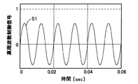
ここで、マップフィルタ部142により生成される低周波数制御信号C1について図5及び図6を参照して説明する。図5は、マップフィルタ部142から出力される低周波数制御信号C1のうち1次周波数成分、2次周波数成分、及び3次周波数成分のそれぞれを示す図である。図6は、図5の各次周波数成分を合成した低周波数制御信号C1を示す図である。なお、図5及び図6は、パルス信号の周波数fが30Hzの場合の低周波数制御信号C1であって、最大値が1となるように示している。
(4.2) Low frequency control signal C1
Here, the low frequency control signal C1 generated by the
マップフィルタ部142により生成される低周波数制御信号C1は、数1に基づき算出される。ここでは、次数kを3次までとするので、数1においてK=3となる。そして、数1に示すように、低周波数制御信号C1は、パルス信号の周波数fの1次周波数成分S1、2次周波数成分S2、及び3次周波数成分S3を合成した信号である。ここで、1次周波数成分S1、2次周波数成分S2、及び3次周波数成分S3は、正弦波信号である。なお、ofsetは、予め車両に応じて設定される値である。
The low frequency control signal C1 generated by the

そして、数1に基づき得られる低周波数制御信号C1の各次周波数成分S1〜S3の信号波形は図5のようになる。そして、各次周波数成分S1〜S3を合成した信号波形C1は図6のようになる。
And the signal waveform of each order frequency component S1-S3 of the low frequency control signal C1 obtained based on
(5)適応制御部15の詳細構成及び高周波数制御信号C2
(5.1)適応制御部15の詳細構成
次に、適応制御部15の詳細構成について図7を参照して説明する。図7は、適応制御部15の構成を示すブロック図である。ここで、適応制御部15において採用する適応制御法は、遅延調和シンセサイザ最小平均自乗フィルタ(DXHS−LMS)である。なお、適応制御部15は、上述したように、モード切替部12により適応制御モードに切り替えられた場合に実行される。
(5) Detailed configuration of
(5.1) Detailed Configuration of
図7に示すように、適応制御部15は、適応フィルタ部151と、伝達関数推定部152と、フィルタ係数更新部153とから構成される。適応フィルタ部151は、周波数算出部11により算出されたパルス信号の周波数f、フィルタ係数更新部153により更新されたフィルタ係数を入力する。そして、適応フィルタ部151は、入力されたこれらの情報に基づき、振幅補償及び位相補償がされて周期性制御信号(高周波数制御信号)C2を生成する。生成した高周波数制御信号C2を駆動部16へ出力する。
As shown in FIG. 7, the
伝達関数推定部152は、適応フィルタ部151の出力制御対象系の伝達関数G(駆動部16及び加振器17)の推定値G^(以下、「推定伝達関数G^」という)を算出する。フィルタ係数更新部153は、加速度センサ18の出力信号と推定伝達関数G^とに基づき、DXHS−LMSによりフィルタ係数を更新する。ここで、フィルタ係数は、フィルタ係数ゲインに相当する振幅値a及びフィルタ係数位相に相当する位相値φである。
The transfer
つまり、適応制御部15は、観測点の誤差である加速度センサ18の出力信号が0となるように、フィルタ係数が更新される。そして、更新されたフィルタ係数に基づき、振幅補償及び位相補償がされた高周波数制御信号C2を出力している。
That is, the
(5.2)高周波数制御信号C2
ここで、適応フィルタ部151により生成される高周波数制御信号C2について図8及び図9を参照して説明する。図8は、適応フィルタ部151により生成される補正前の正弦波信号状態の高周波数制御信号を示す図である。図9は、適応フィルタ部151から出力される高周波数制御信号C2を示す図である。なお、図8及び図9は、パルス信号の周波数fが100Hzの場合の高周波数制御信号であって、最大値が1となるように示している。
(5.2) High frequency control signal C2
Here, the high frequency control signal C2 generated by the
まず、適応フィルタ部151により生成される補正前の高周波数制御信号S1は、数2に基づき算出される。ここでは、次数kは1次とするので、数2においてK=1となる。つまり、補正前の高周波数制御信号S1は、パルス信号の周波数fの1次周波数成分S1のみからなる正弦波信号である。この補正前の高周波数制御信号S1の波形は、図8のような正弦波となる。
First, the high-frequency control signal S1 before correction generated by the
続いて、算出された補正前の高周波数制御信号S1に対して、数3により補正を行う。この補正後の高周波数制御信号C2が、駆動部16へ出力される信号である。つまり、数3により、補正前の正弦波信号を矩形波信号に変換している。この補正後の高周波数制御信号C2は、図9のような矩形波となる。
Subsequently, the calculated high-frequency control signal S1 before correction is corrected by Equation 3. The corrected high frequency control signal C2 is a signal output to the
![]()
![]()
(6)駆動部16の詳細構成
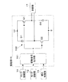
次に、駆動部16の詳細構成について図10を参照して説明する。図10は、駆動部16の構成を示す図である。図10に示すように、駆動部16は、駆動信号出力部161と非対称型ハーフブリッジ回路162とから構成される。
(6) Detailed Configuration of
(6.1)駆動信号出力部161の構成
駆動信号出力部161は、上述したモード切替部12から出力される制御モード、並びに、マップ制御部14又は適応制御部15から出力される周期性制御信号C1、C2に基づき、後述するハイサイドスイッチQ1及びローサイドスイッチQ2の駆動信号を出力する。具体的には、駆動信号出力部161は、ハイサイドスイッチQ1及びローサイドスイッチQ2のゲート電圧を出力する。
(6.1) Configuration of Drive
(6.2)非対称型ハーフブリッジ回路162の構成
非対称型ハーフブリッジ回路162は、いわゆるHブリッジ回路を構成しており、第1上アームには第1ダイオードD1が接続され、第1下アームにはローサイドスイッチQ2が接続されている。第2上アームにはハイサイドスイッチQ1が接続され、第2下アームには第2ダイオードD2が接続されている。ここで、ハイサイドスイッチQ1及びローサイドスイッチQ2は、何れもFETを用いている。
(6.2) Configuration of Asymmetric Half-
具体的には、第1ダイオードD1のカソード側が正極側に接続され、第1ダイオードD1のアノード側とローサイドスイッチQ2のドレイン側とが接続され、ローサイドスイッチQ2のソース側が負極側に接続されている。また、ハイサイドスイッチQ1のドレイン側が正極側に接続され、ハイサイドスイッチQ1のソース側と第2ダイオードD2のカソード側とが接続され、第2ダイオードD2のアノード側が負極側に接続されている。なお、ハイサイドスイッチQ1及びローサイドスイッチQ2のゲート側は、駆動信号出力部161に接続されている。つまり、駆動信号出力部161から出力されるゲート電圧に応じて、ハイサイドスイッチQ1及びローサイドスイッチQ2はオンオフ駆動する。
Specifically, the cathode side of the first diode D1 is connected to the positive side, the anode side of the first diode D1 and the drain side of the low side switch Q2 are connected, and the source side of the low side switch Q2 is connected to the negative side. . The drain side of the high side switch Q1 is connected to the positive side, the source side of the high side switch Q1 and the cathode side of the second diode D2 are connected, and the anode side of the second diode D2 is connected to the negative side. Note that the gate sides of the high-side switch Q1 and the low-side switch Q2 are connected to the drive
そして、非対称型ハーフブリッジ回路162の出力側には加振器17が接続されている。すなわち、第1ダイオードD1とローサイドスイッチQ2との中間位置、及び、ハイサイドスイッチQ1と第2ダイオードD2の中間位置が、加振器17であるソレノイドのコイルの両端側にそれぞれ接続されている。
A
(6.3)駆動部16の処理動作
上述のような構成からなる駆動部16の処理動作について図11〜図14を参照して説明する。
(6.3) Processing Operation of
(6.3.1)駆動信号出力部161の処理動作
まず、駆動信号出力部161の処理動作について、図11のフローチャートを参照して説明する。図11は、駆動信号出力部161の処理動作を示すフローチャートである。
(6.3.1) Processing Operation of Drive
図11に示すように、駆動信号出力部161は、まずモード切替部12から制御モードを入力する(ステップS11)。続いて、入力された制御モードがマップ制御モードであるか否かを判定する(ステップS12)。そして、入力された制御モードがマップ制御モードである場合には(ステップS12:Yes)、マップ制御部14から低周波数制御信号C1を入力する。低周波数制御信号C1は、上述したように図6に示す信号である。
As shown in FIG. 11, the drive
続いて、マップ制御部14から入力された低周波数制御信号C1が正であるか負であるかを判定する(ステップS14)。低周波数制御信号C1が正の場合には(ステップS14:Yes)、ハイサイドスイッチQ1をオン駆動させ、ローサイドスイッチQ2を低周波数制御信号C1に基づき算出されたDUTYによりPWM駆動させる信号を各スイッチQ1,Q2に出力する(ステップS15)。すなわち、図6におけるT1以外の区間にて、上記駆動信号が出力される。
Subsequently, it is determined whether the low frequency control signal C1 input from the
一方、マップ制御部14から入力された低周波数制御信号C1が負の場合には(ステップS14:No)、低周波数制御信号C1の絶対値を算出する(ステップS16)。続いて、ハイサイドスイッチQ1をオフ駆動させ、ローサイドスイッチQ2を低周波数制御信号C1の絶対値に基づき算出されたDUTYによりPWM駆動させる信号を各スイッチQ1,Q2に出力する(ステップS17)。すなわち、図6におけるT1区間において、上記駆動信号が出力される。
On the other hand, when the low frequency control signal C1 input from the
また、入力された制御モードがマップ制御モードでない場合、すなわち、適応制御モードである場合には(ステップS12:No)、適応制御部15から高周波数制御信号C2を入力する。高周波数制御信号C2は、上述したように図9に示す信号である。続いて、適応制御部15から入力された高周波数制御信号C2が正であるか負であるかを判定する(ステップS19)。高周波数制御信号C2が正の場合には(ステップS19:Yes)、ハイサイドスイッチQ1をオン駆動させ、ローサイドスイッチQ2を高周波数制御信号C2に基づき算出されたDUTYによりPWM駆動させる信号を各スイッチQ1,Q2に出力する(ステップS20)。すなわち、図9におけるT2以外の区間にて、上記駆動信号が出力される。
When the input control mode is not the map control mode, that is, when it is the adaptive control mode (step S12: No), the high frequency control signal C2 is input from the
一方、適応制御部15から入力された高周波数制御信号C2が負の場合には(ステップS19:No)、ハイサイドスイッチQ1及びローサイドスイッチQ2をオフ駆動させる信号を各スイッチQ1,Q2に出力する(ステップS21)。すなわち、図9におけるT2区間にて、上記駆動信号が出力される。
On the other hand, when the high frequency control signal C2 input from the
(6.3.2)非対称型ハーフブリッジ回路162の動作
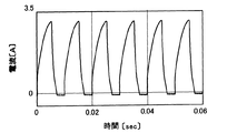
次に、非対称型ハーフブリッジ回路162の動作について、図12〜図14を参照して説明する。図12(a)〜図12(c)は、各スイッチQ1,Q2の動作に応じて非対称型ハーフブリッジ回路162に流れる電流を示す図である。図13は、マップ制御モードにおける加振器17であるソレノイドのコイルに流れる電流値を示す図である。図14は、適応制御モードにおける加振器17であるソレノイドのコイルに流れる電流値を示す図である。以下に、制御モード及び各スイッチQ1,Q2の動作毎に説明する。
(6.3.2) Operation of the asymmetric half-
(6.3.2.1)マップ制御モードにおいて低周波数制御信号C1が正の場合
まず、マップ制御モードにおいて低周波数制御信号C1が正の場合について図12(a)及び図13を参照して説明する。この場合には、ハイサイドスイッチQ1がオン駆動し、ローサイドスイッチQ2がPWM駆動する。このときの非対称型ハーフブリッジ回路162には、図12(a)の矢印にて示すように電流が流れる。すなわち、電流は、正極側→ハイサイドスイッチQ1→加振器17のコイル→ローサイドスイッチQ2→負極側の方向に流れる。なお、ローサイドスイッチQ2がPWM駆動しているので、そのDUTYに応じた電流が流れることになる。
(6.3.2.1) In the case where the low frequency control signal C1 is positive in the map control mode First, the case where the low frequency control signal C1 is positive in the map control mode will be described with reference to FIGS. explain. In this case, the high side switch Q1 is turned on and the low side switch Q2 is PWM driven. A current flows through the asymmetric half-
具体的には、図6及び図13に示すように、低周波数制御信号の値が大きい場合には加振器17のコイルに流れる電流値が大きくなり、低周波数制御信号の値が小さい場合には加振器17のコイルに流れる電流値が小さくなる。ここで、加振器17により発生する加振力は、コイルに流れる電流に比例する。従って、低周波数制御信号C1が正の場合には、加振器17は、1次周波数成分S1、2次周波数成分S2、及び3次周波数成分S3を考慮した加振力を発生することができる。
Specifically, as shown in FIGS. 6 and 13, when the value of the low frequency control signal is large, the value of the current flowing through the coil of the
(6.3.2.2)マップ制御モードにおいて低周波数制御信号C1が負の場合
次に、マップ制御モードにおいて低周波数制御信号C1が負の場合について図12(b)及び図13を参照して説明する。この場合には、ハイサイドスイッチQ1がオフ駆動し、ローサイドスイッチQ2がPWM駆動する。このときの非対称型ハーフブリッジ回路162には、図12(b)の矢印にて示すように環流電流が流れる。すなわち、電流は、第2ダイオードD2→加振器17のコイル→ローサイドスイッチQ2→第2ダイオードD2の方向に環流する。この環流電流が流れるのは、加振器17のコイルのインダクタンスの作用によるものである。従って、時間が経過するにつれて、環流電流は徐々に減少する。具体的には、図13に示すように、T1区間において、加振器17のコイルに流れる電流が減少している。
(6.3.2.2) Case where Low Frequency Control Signal C1 is Negative in Map Control Mode Next, a case where the low frequency control signal C1 is negative in the map control mode will be described with reference to FIGS. I will explain. In this case, the high side switch Q1 is turned off and the low side switch Q2 is PWM driven. At this time, a circulating current flows through the asymmetric half-
ここで、ローサイドスイッチQ2をPWM駆動させる理由について説明する。ハイサイドスイッチQ1及びローサイドスイッチQ2を共にオフ駆動する場合に比べて、ハイサイドスイッチQ1をオフ駆動しローサイドスイッチQ2をPWM駆動する場合には、加振器17のコイルに流れる電流値の減少率が低減する結果が得られた。その結果、ローサイドスイッチQ2をPWM駆動することにより、加振器17のコイルに流れる電流値が0にならないようにすることができる。このように電流値が0にならないようにすることで、加振器17のコイルの通電状態がオン状態からオフ状態になることを抑制することができる。つまり、加振器17のコイルの通電状態がオン状態からオフ状態になることによる異音の発生を抑制することができる。
Here, the reason why the low-side switch Q2 is PWM driven will be described. Compared with the case where both the high-side switch Q1 and the low-side switch Q2 are driven off, when the high-side switch Q1 is driven off and the low-side switch Q2 is PWM-driven, the rate of decrease of the current value flowing through the coil of the
(6.3.2.3)適応制御モードにおいて高周波数制御信号C2が正の場合
次に、適応制御モードにおいて高周波数制御信号C2が正の場合について図12(a)及び図14を参照して説明する。この場合には、ハイサイドスイッチQ1がオン駆動し、ローサイドスイッチQ2がPWM駆動する。このときの非対称型ハーフブリッジ回路162には、図12(a)の矢印にて示すように電流が流れる。ここで、高周波数制御信号C2は図9に示すように、矩形波信号である。従って、ローサイドスイッチQ2は一定のDUTYに基づきPWM駆動する。つまり、高周波数制御信号C2が正の場合には、図14に示すように、一定の時定数に基づき電流値は上昇する。さらに、高周波数制御信号C2を矩形波信号とすることにより、コイルに流れる電流値の上昇率を大きくすることができる。その結果、加振器17により大きな加振力を発生させることができる。
(6.3.2.3) When the high-frequency control signal C2 is positive in the adaptive control mode Next, with reference to FIGS. 12A and 14 for the case where the high-frequency control signal C2 is positive in the adaptive control mode. I will explain. In this case, the high side switch Q1 is turned on and the low side switch Q2 is PWM driven. A current flows through the asymmetric half-
(6.3.2.4)適応制御モードにおいて高周波数制御信号C2が負の場合
次に、適応制御モードにおいて高周波数制御信号C2が負の場合について図12(c)及び図14を参照して説明する。この場合には、ハイサイドスイッチQ1及びローサイドスイッチQ2が共にオフ駆動する。このときの非対称型ハーフブリッジ回路162には、図12(c)の矢印にて示すように回生電流が流れる。すなわち、電流は、負極側→第2ダイオードD2→加振器17のコイル→第1ダイオードD1→正極側の方向に流れる。この場合、図14に示すように、一定の時定数に基づき急速に電流値が減少して零になる。
(6.3.2.4) In the case where the high frequency control signal C2 is negative in the adaptive control mode Next, the case where the high frequency control signal C2 is negative in the adaptive control mode will be described with reference to FIGS. I will explain. In this case, both the high side switch Q1 and the low side switch Q2 are turned off. A regenerative current flows through the asymmetric half-
(7)効果
(7.1)マップ制御モードにおける効果
マップ制御モードにおいては、パルス信号の周波数fの高次周波数成分を考慮した低周波数制御信号C1に基づく加振力を加振器17は発生している。つまり、エンジンによる振動の高次周波数成分に対しても適切に防振することができる。その結果、エンジンによる振動の高次周波数成分がエンジンフレームの固有振動数と一致する場合であっても、振動を抑制することができる。
(7) Effects (7.1) Effects in the map control mode In the map control mode, the
さらに、加振器17のコイルに流れる電流が0にならないように制御している。つまり、加振器17の通電状態がオン状態からオフ状態になることを抑制することができる。従って、加振器17の通電状態がオン状態からオフ状態になることにより生じる異音を抑制することができる。
Furthermore, control is performed so that the current flowing through the coil of the
(7.2)適応制御モードにおける効果
適応制御モードにおいては、矩形波に補正された高周波数制御信号C2に基づき加振器17を駆動している。これにより、応答性を良くすることができ、加振器17により高い加振力を発生させることができる。その結果、エンジンが高回転となる場合であっても、適切に振動を抑制することができる。
(7.2) Effect in Adaptive Control Mode In the adaptive control mode, the
(8)他の実施例
(8.1)他の低周波数制御信号C3及びその場合の加振器17に流れる電流値
(8.1.1)他の低周波数制御信号C3の概要
上記実施例における低周波数制御信号C1は、正弦波からなる1次周波数成分S1、2次周波数成分S2、及び3次周波数成分S3を合成した信号としたが、以下の低周波数制御信号C3を用いてもよい。なお、上記実施例における低周波数制御信号C1によれば、加振器17により発生する加振力は小さいが、エンジンにより発生する振動に適切に対応した加振力を発生することができるので、非常に高い静粛性を得ることができる。一方、以下の低周波数制御信号C3は、大きな加振力を得ることができるようにすることができる。
(8) Other embodiments (8.1) Other low frequency control signal C3 and current value flowing through the
(8.1.2)低周波数制御信号C3の詳細
他の低周波数制御信号C3について図15及び図16を参照して説明する。図15は、マップフィルタ部142から出力される低周波数制御信号C3のうち1次周波数成分P1、2次周波数成分S2、及び3次周波数成分S3のそれぞれを示す図である。図16は、図15の各次数周波数成分を合成した低周波数制御信号C3を示す図である。なお、図15及び図16は、パルス信号の周波数fが30Hzの場合の低周波数制御信号C3であって、最大値が1となるように示している。
(8.1.2) Details of Low Frequency Control Signal C3 Another low frequency control signal C3 will be described with reference to FIG. 15 and FIG. FIG. 15 is a diagram illustrating each of the primary frequency component P1, the secondary frequency component S2, and the tertiary frequency component S3 in the low frequency control signal C3 output from the
マップフィルタ部142により生成される低周波数制御信号C3は、数4〜数6に基づき算出される。数4は、低周波数制御信号C3のうちの1次周波数成分P1を示す。この1次周波数成分P1は、図15に示すような矩形波信号となる。数5は、低周波数制御信号C3のうちの2次周波数成分S2及び3次周波数成分S3を示す。この2次周波数成分S2及び3次周波数成分S3は、図15に示すような正弦波信号となる。そして、数6は、低周波数制御信号C3である。低周波数制御信号C3は、矩形波信号に変換された1次周波数成分P1と、正弦波信号である2周波数成分S2及び3次周波数成分S3とを合成したものである。ただし、最大値がa1とされている。
The low frequency control signal C3 generated by the
(8.1.3)上記の場合における加振器17に流れる電流値
上述のような低周波数制御信号C3に基づき駆動部16が駆動した場合における加振器17のコイルに流れる電流値について図17を参照して説明する。図17は、当該電流値を示す図である。ここで、駆動部16の処理動作は、上述した駆動部16の処理動作と同様である。すなわち、マップ制御モードにおいて低周波数制御信号C3が正の場合には、駆動部16は、ハイサイドスイッチQ1をオン駆動させ、ローサイドスイッチQ2をPWM駆動させる。一方、マップ制御モードにおいて低周波数制御信号C3が負の場合には、駆動部16は、ハイサイドスイッチQ1をオフ駆動させ、ローサイドスイッチQ2をPWM駆動させる。
(8.1.3) Current value flowing through the
そして、低周波数制御信号C3に基づき駆動部16が駆動した場合に、加振器17のコイルに流れる電流値は、図17に示すようになる。すなわち、低周波数制御信号C3が正の場合に電流値が上昇し、低周波数制御信号C3が負の場合に電流値が減少している。さらに、低周波数制御信号C1に基づき駆動部16が駆動した場合に比べると、低周波数制御信号C3に基づき駆動部16が駆動した場合は、加振器17のコイルに流れる電流値が大きい。つまり、低周波数制御信号C3に基づき駆動部16を駆動した場合は、加振器17により大きな加振力を発生させることができる。さらに、低周波数制御信号C3が負の場合にコイルに流れる電流値は減少しているが、0には到達していない。つまり、加振器17の通電状態がオン状態からオフ状態になることを抑制することができる。従って、加振器17の通電状態がオン状態からオフ状態になることにより生じる異音を抑制することができる。
And when the
(8.2)駆動信号出力部161により出力される他の駆動信号
上述した実施例における駆動信号は、低周波数制御信号C1及び高周波数制御信号C2が正の場合には、ハイサイドスイッチQ1をオン駆動させ、ローサイドスイッチQ2をPWM駆動させる信号としている。この駆動信号は、低周波数制御信号C1及び高周波数制御信号C2が正の場合に、ハイサイドスイッチQ1及びローサイドスイッチQ2をPWM駆動させる信号としてもよい。この場合、ハイサイドスイッチQ1のPWM信号とローサイドスイッチQ2のPWM信号とは、同期をとって駆動するようにしてもよいし、位相をずらして駆動するようにしてもよい。
(8.2) Other Drive Signals Output from the Drive
また、上記駆動信号は、マップ制御モードであって低周波数制御信号C1が負の場合には、ハイサイドスイッチQ1をオフ駆動させ、ローサイドスイッチQ2をPWM駆動させる信号としている。この駆動信号は、マップ制御モードであって低周波数制御信号C1が負の場合には、ハイサイドスイッチQ1をPWM駆動させ、ローサイドスイッチQ2をオフ駆動させる信号としてもよい。これらの場合であっても、上記と同様の効果を奏する。 The drive signal is a signal for driving the high-side switch Q1 off and the PWM drive of the low-side switch Q2 when the low-frequency control signal C1 is negative in the map control mode. This drive signal may be a signal that causes the high-side switch Q1 to be driven by PWM and the low-side switch Q2 to be turned off when the low-frequency control signal C1 is negative in the map control mode. Even in these cases, the same effects as described above can be obtained.
(8.3)モード切替部12による他のモード切替処理
上述した実施例におけるモード切替処理は、パルス信号の周波数fのみにより択一的にマップ制御モードと適応制御モードとを切り替えるようにしている。その他に、例えば、周波数f及び車速を考慮して、制御モードを切り替えるようにしてもよい。例えば、低周波数であって低車速の場合にマップ制御モードとし、高周波数であって高車速の場合に適応制御モードとしてもよい。
(8.3) Other Mode Switching Processes by the
(8.4)モード切替部12による切替周波数
上述した実施例においてモード切替部12によりマップ制御モードと適応制御モードとを切り替える周波数を50Hzとしたが、適宜変更してもよい。エンジンフレームに限らず、他の構成部品の固有振動数を考慮してもよい。部品の固有振動数の他にも種々の条件を考慮して制御モードを切り替える周波数を設定してもよい。
(8.4) Switching frequency by
(8.5)低周波数制御信号C1
低周波数制御信号C1は、1次周波数成分から3次周波数成分までを考慮したが、より高次周波数成分を考慮するようにしてもよい。これにより、より高次の振動に対しても抑制することができる。
(8.5) Low frequency control signal C1
Although the low-frequency control signal C1 considers the primary frequency component to the tertiary frequency component, higher frequency components may be considered. Thereby, it can suppress also to a higher order vibration.
1:能動型防振装置、 11:周波数算出部、 12:モード切替部、 13:運転状態信号出力部、 14:マップ制御部(制御信号発生手段)、 15:適応制御部(制御信号発生手段)、 16:駆動部(駆動手段)、 17:加振器(電磁アクチュエータ)、 18:加速度センサ、 20:加振器付エンジンマウント、 21:ケース、 22:防振ゴム、 24:固定金具、 161:駆動信号出力部、 162:非対称型ハーフブリッジ回路、 Q1:ハイサイドスイッチ、 Q2:ローサイドスイッチ DESCRIPTION OF SYMBOLS 1: Active vibration isolator, 11: Frequency calculation part, 12: Mode switching part, 13: Operation state signal output part, 14: Map control part (control signal generation means), 15: Adaptive control part (control signal generation means) ), 16: drive unit (drive means), 17: vibrator (electromagnetic actuator), 18: acceleration sensor, 20: engine mount with vibrator, 21: case, 22: anti-vibration rubber, 24: fixing bracket, 161: Drive signal output unit, 162: Asymmetric half-bridge circuit, Q1: High side switch, Q2: Low side switch
Claims (7)
車両の振動発生源から出力される周期性のパルス信号に基づき車両特定部位の振動を能動的に抑制させる周期性制御信号を発生する制御信号発生手段と、
前記周期性制御信号に基づき前記電磁アクチュエータへの前記電流通電量を可変にして前記電磁アクチュエータを駆動する駆動手段と、
を備える能動型防振装置において、
前記駆動手段は、
少なくとも前記電磁アクチュエータの正極側に接続されたハイサイドスイッチと前記電磁アクチュエータの負極側に接続され該ハイサイドスイッチに対して非対称位置に配置されたローサイドスイッチとを有する非対称型ハーフブリッジ回路と、
前記周期性制御信号が正の場合に前記ハイサイドスイッチ及び前記ローサイドスイッチのうち何れか一方にオン駆動信号を出力し他方に前記周期性制御信号に基づきPWM駆動信号を出力しあるいは前記ハイサイドスイッチ及び前記ローサイドスイッチの何れもに前記周期性制御信号に基づきPWM駆動信号を出力し、前記周期性制御信号が負の場合に前記ハイサイドスイッチ及び前記ローサイドスイッチのうち何れか一方にオフ駆動信号を出力し他方に前記周期性制御信号に基づきPWM駆動信号を出力する駆動信号出力手段と、
を有することを特徴とする能動型防振装置。 An electromagnetic actuator that generates an excitation force by making the amount of current flow variable,
Control signal generating means for generating a periodic control signal for actively suppressing vibration of a specific part of the vehicle based on a periodic pulse signal output from a vibration generation source of the vehicle;
Drive means for driving the electromagnetic actuator by varying the amount of current applied to the electromagnetic actuator based on the periodicity control signal;
In an active vibration isolator comprising:
The driving means includes
An asymmetric half-bridge circuit having at least a high-side switch connected to the positive electrode side of the electromagnetic actuator and a low-side switch connected to the negative electrode side of the electromagnetic actuator and disposed at an asymmetric position with respect to the high-side switch;
When the periodic control signal is positive, an ON drive signal is output to one of the high-side switch and the low-side switch, and a PWM drive signal is output to the other based on the periodic control signal, or the high-side switch And the low side switch outputs a PWM drive signal based on the periodic control signal, and when the periodic control signal is negative, an off drive signal is output to either the high side switch or the low side switch. Drive signal output means for outputting and outputting a PWM drive signal based on the periodicity control signal to the other side;
An active vibration isolator characterized by comprising:
前記パルス信号の周波数が所定周波数以下の場合には前記パルス信号の周波数の1次周波数成分信号と前記パルス信号の周波数に対する高次周波数成分信号とを合わせた低周波数制御信号であり、
前記パルス信号の周波数が前記所定周波数より大きい場合には前記1次周波数成分信号のみからなる高周波数制御信号であることを特徴とする請求項1記載の能動型防振装置。 The periodicity control signal is
When the frequency of the pulse signal is equal to or lower than a predetermined frequency, a low-frequency control signal that combines a primary frequency component signal of the frequency of the pulse signal and a high-order frequency component signal with respect to the frequency of the pulse signal,
Active vibration damping device according to claim 1, wherein the frequency of the pulse signal is greater than the predetermined frequency, which is a high-frequency control signal comprising only the primary frequency component signal.
前記周期性制御信号が負であって前記パルス信号の周波数が所定周波数以下の場合に前記ハイサイドスイッチ及び前記ローサイドスイッチのうち何れか一方にオフ駆動信号を出力し他方に前記周期性制御信号に基づきPWM駆動信号を出力し、
前記周期性制御信号が負であって前記パルス信号の周波数が前記所定周波数より大きい場合に前記ハイサイドスイッチ及び前記ローサイドスイッチにオフ駆動信号を出力することを特徴とする請求項1記載の能動型防振装置。 The drive signal output means includes
When the periodic control signal is negative and the frequency of the pulse signal is equal to or lower than a predetermined frequency, an off drive signal is output to one of the high-side switch and the low-side switch and the periodic control signal is output to the other. Based on the PWM drive signal ,
Active of claim 1, wherein said cyclic control signal the frequency of the pulse signal a negative outputs an OFF driving signal to the high-side switch and the low-side switch is greater than a predetermined frequency Anti-vibration device.
前記パルス信号の周波数が所定周波数以下の場合に予め記憶されたデータマップ及び制御時の運転状態に基づき前記周期性制御信号を算出し、
前記パルス信号の周波数が前記所定周波数より大きい場合に適応制御法に基づき前記周期性制御信号を算出することを特徴とする請求項1〜6の何れか一項に記載の能動型防振装置。 The control signal generating means is
When the frequency of the pulse signal is equal to or lower than a predetermined frequency, the periodic control signal is calculated based on a data map stored in advance and an operating state at the time of control,
Active vibration damping device according to any one of claims 1 to 6, characterized in that the frequency of the pulse signal to calculate the cyclic control signals based on the adaptive control law is greater than the predetermined frequency.
Priority Applications (5)
| Application Number | Priority Date | Filing Date | Title |
|---|---|---|---|
| JP2004222905A JP4490199B2 (en) | 2004-07-30 | 2004-07-30 | Active vibration isolator |
| EP05015808A EP1621795B1 (en) | 2004-07-30 | 2005-07-20 | Active vibration insulator |
| DE602005024085T DE602005024085D1 (en) | 2004-07-30 | 2005-07-20 | Active vibration isolator |
| US11/190,170 US7209338B2 (en) | 2004-07-30 | 2005-07-27 | Active vibration insulator |
| CNB2005100876933A CN100392284C (en) | 2004-07-30 | 2005-07-29 | Active vibration insulator |
Applications Claiming Priority (1)
| Application Number | Priority Date | Filing Date | Title |
|---|---|---|---|
| JP2004222905A JP4490199B2 (en) | 2004-07-30 | 2004-07-30 | Active vibration isolator |
Publications (2)
| Publication Number | Publication Date |
|---|---|
| JP2006038188A JP2006038188A (en) | 2006-02-09 |
| JP4490199B2 true JP4490199B2 (en) | 2010-06-23 |
Family
ID=35241033
Family Applications (1)
| Application Number | Title | Priority Date | Filing Date |
|---|---|---|---|
| JP2004222905A Expired - Lifetime JP4490199B2 (en) | 2004-07-30 | 2004-07-30 | Active vibration isolator |
Country Status (5)
| Country | Link |
|---|---|
| US (1) | US7209338B2 (en) |
| EP (1) | EP1621795B1 (en) |
| JP (1) | JP4490199B2 (en) |
| CN (1) | CN100392284C (en) |
| DE (1) | DE602005024085D1 (en) |
Families Citing this family (12)
| Publication number | Priority date | Publication date | Assignee | Title |
|---|---|---|---|---|
| JP4490199B2 (en) | 2004-07-30 | 2010-06-23 | 東海ゴム工業株式会社 | Active vibration isolator |
| KR101236662B1 (en) | 2006-05-08 | 2013-02-22 | 신포니아 테크놀로지 가부시키가이샤 | Damper for automobiles for reducing vibration of automobile body |
| JP5092365B2 (en) * | 2006-11-21 | 2012-12-05 | アイコム株式会社 | Support foot mounting structure |
| CN103210235B (en) * | 2011-06-28 | 2015-07-15 | 住友理工株式会社 | Active vibration/noise suppression device |
| US9480177B2 (en) | 2012-07-27 | 2016-10-25 | Emerson Climate Technologies, Inc. | Compressor protection module |
| JP2015054661A (en) * | 2013-09-13 | 2015-03-23 | 日立オートモティブシステムズ株式会社 | Vibration reduction device |
| WO2016192680A1 (en) * | 2015-06-03 | 2016-12-08 | Triastek, Inc. | Dosage forms and use thereof |
| WO2016197148A1 (en) * | 2015-06-05 | 2016-12-08 | Kielbania Andrew J Jr | All-in-one air cleaner/odor eliminator, surface disinfectant and surface multipurpose/all purpose cleaner |
| CN109264316A (en) * | 2018-10-29 | 2019-01-25 | 安徽中科光电色选机械有限公司 | A kind of more vibrator control devices of color selector |
| CN111271140A (en) * | 2020-01-17 | 2020-06-12 | 南京航空航天大学 | Active vibration control device and vibration control method |
| CN112078523B (en) * | 2020-09-28 | 2022-06-17 | 湖南行必达网联科技有限公司 | Engine support monitoring method and system |
| TWI757090B (en) * | 2021-02-08 | 2022-03-01 | 茂達電子股份有限公司 | Overvoltage protecting system and method of motor pre-driver |
Citations (4)
| Publication number | Priority date | Publication date | Assignee | Title |
|---|---|---|---|---|
| JP2000179611A (en) * | 1998-12-11 | 2000-06-27 | Bridgestone Corp | Vibration control device |
| JP2001117644A (en) * | 1999-10-21 | 2001-04-27 | Tokai Rubber Ind Ltd | Method for controlling electromagnetic vibration generation and the same device electromagnetic vibration generator |
| JP2003202902A (en) * | 2002-01-07 | 2003-07-18 | Tokai Rubber Ind Ltd | Active vibration control method using adaptive control method |
| JP2004034826A (en) * | 2002-07-03 | 2004-02-05 | Honda Motor Co Ltd | Engine vibration prevention control device |
Family Cites Families (14)
| Publication number | Priority date | Publication date | Assignee | Title |
|---|---|---|---|---|
| JPH08177965A (en) * | 1994-12-26 | 1996-07-12 | Nippondenso Co Ltd | Engine mount |
| JPH08177961A (en) * | 1994-12-27 | 1996-07-12 | Nissan Motor Co Ltd | Vibration proof supporting device |
| JPH08200435A (en) * | 1995-01-24 | 1996-08-06 | Matsushita Electric Ind Co Ltd | Periodic vibration reducing device |
| US5872703A (en) * | 1997-08-25 | 1999-02-16 | The Charles Machine Works, Inc. | System and method for regulating power in tank circuits having a bridge configuration |
| JP3952584B2 (en) | 1997-12-05 | 2007-08-01 | 東海ゴム工業株式会社 | Active vibration isolator |
| JPH11259147A (en) | 1998-03-11 | 1999-09-24 | Tokai Rubber Ind Ltd | Setting method for map data of controller active vibration-proof device |
| JPH11272339A (en) * | 1998-03-19 | 1999-10-08 | Tokai Rubber Ind Ltd | Active type vibration isolator |
| US6249418B1 (en) * | 1999-01-27 | 2001-06-19 | Gary Bergstrom | System for control of an electromagnetic actuator |
| JP4082837B2 (en) * | 1999-11-19 | 2008-04-30 | 東海ゴム工業株式会社 | Active vibration isolator control method and active vibration isolator |
| CZ302554B6 (en) * | 2000-10-26 | 2011-07-13 | Heidelberger Druckmaschinen Ag | Method for compensating mechanical oscillation, particularly in printing machines |
| JP2003047260A (en) * | 2001-05-22 | 2003-02-14 | Aisin Seiki Co Ltd | Driving method for bridge circuit for driving inductance load |
| JP3842643B2 (en) | 2001-12-25 | 2006-11-08 | 東海ゴム工業株式会社 | Active vibration control method using adaptive control method |
| JP3811431B2 (en) | 2002-07-03 | 2006-08-23 | 本田技研工業株式会社 | Actuator drive control method for active vibration isolation support device |
| JP4490199B2 (en) | 2004-07-30 | 2010-06-23 | 東海ゴム工業株式会社 | Active vibration isolator |
-
2004
- 2004-07-30 JP JP2004222905A patent/JP4490199B2/en not_active Expired - Lifetime
-
2005
- 2005-07-20 DE DE602005024085T patent/DE602005024085D1/en active Active
- 2005-07-20 EP EP05015808A patent/EP1621795B1/en not_active Ceased
- 2005-07-27 US US11/190,170 patent/US7209338B2/en active Active
- 2005-07-29 CN CNB2005100876933A patent/CN100392284C/en not_active Expired - Fee Related
Patent Citations (4)
| Publication number | Priority date | Publication date | Assignee | Title |
|---|---|---|---|---|
| JP2000179611A (en) * | 1998-12-11 | 2000-06-27 | Bridgestone Corp | Vibration control device |
| JP2001117644A (en) * | 1999-10-21 | 2001-04-27 | Tokai Rubber Ind Ltd | Method for controlling electromagnetic vibration generation and the same device electromagnetic vibration generator |
| JP2003202902A (en) * | 2002-01-07 | 2003-07-18 | Tokai Rubber Ind Ltd | Active vibration control method using adaptive control method |
| JP2004034826A (en) * | 2002-07-03 | 2004-02-05 | Honda Motor Co Ltd | Engine vibration prevention control device |
Also Published As
| Publication number | Publication date |
|---|---|
| DE602005024085D1 (en) | 2010-11-25 |
| EP1621795A3 (en) | 2007-09-12 |
| EP1621795A2 (en) | 2006-02-01 |
| US7209338B2 (en) | 2007-04-24 |
| JP2006038188A (en) | 2006-02-09 |
| US20060023388A1 (en) | 2006-02-02 |
| EP1621795B1 (en) | 2010-10-13 |
| CN1727721A (en) | 2006-02-01 |
| CN100392284C (en) | 2008-06-04 |
Similar Documents
| Publication | Publication Date | Title |
|---|---|---|
| EP1621795B1 (en) | Active vibration insulator | |
| EP2023007B1 (en) | Damper for automobiles for reducing vibration of automobile body | |
| JP2005233346A (en) | Setting method and controlling method for control data in active vibration-resistant control system | |
| JP4016966B2 (en) | Driving method of active vibration isolator | |
| JP4203388B2 (en) | Actuator drive controller | |
| JP2006336736A (en) | Active vibration-isolating system | |
| JP4370933B2 (en) | Vibration control method and vibration control device for active vibration isolator | |
| JPH08177961A (en) | Vibration proof supporting device | |
| JP4082837B2 (en) | Active vibration isolator control method and active vibration isolator | |
| JP2006349029A (en) | Active vibration control device | |
| JP6264952B2 (en) | Vibration reduction device | |
| JP3551653B2 (en) | Active noise and vibration control device | |
| JP3470430B2 (en) | Active vibration control device and active vibration control method | |
| JP5085360B2 (en) | Active vibration isolator | |
| CN113678365A (en) | Control device | |
| JP2020070895A (en) | Vibration damping device | |
| KR20160143285A (en) | 2 Coil Active Engine Mount | |
| JPH06340228A (en) | Active engine mount device | |
| JP2008157433A (en) | Active vibration control device |
Legal Events
| Date | Code | Title | Description |
|---|---|---|---|
| A621 | Written request for application examination |
Free format text: JAPANESE INTERMEDIATE CODE: A621 Effective date: 20070112 |
|
| A977 | Report on retrieval |
Free format text: JAPANESE INTERMEDIATE CODE: A971007 Effective date: 20090313 |
|
| A131 | Notification of reasons for refusal |
Free format text: JAPANESE INTERMEDIATE CODE: A131 Effective date: 20090407 |
|
| TRDD | Decision of grant or rejection written | ||
| A01 | Written decision to grant a patent or to grant a registration (utility model) |
Free format text: JAPANESE INTERMEDIATE CODE: A01 Effective date: 20100325 |
|
| A01 | Written decision to grant a patent or to grant a registration (utility model) |
Free format text: JAPANESE INTERMEDIATE CODE: A01 |
|
| A61 | First payment of annual fees (during grant procedure) |
Free format text: JAPANESE INTERMEDIATE CODE: A61 Effective date: 20100401 |
|
| FPAY | Renewal fee payment (event date is renewal date of database) |
Free format text: PAYMENT UNTIL: 20130409 Year of fee payment: 3 |
|
| R150 | Certificate of patent or registration of utility model |
Ref document number: 4490199 Country of ref document: JP Free format text: JAPANESE INTERMEDIATE CODE: R150 Free format text: JAPANESE INTERMEDIATE CODE: R150 |
|
| FPAY | Renewal fee payment (event date is renewal date of database) |
Free format text: PAYMENT UNTIL: 20130409 Year of fee payment: 3 |
|
| FPAY | Renewal fee payment (event date is renewal date of database) |
Free format text: PAYMENT UNTIL: 20140409 Year of fee payment: 4 |
|
| S111 | Request for change of ownership or part of ownership |
Free format text: JAPANESE INTERMEDIATE CODE: R313117 |
|
| S533 | Written request for registration of change of name |
Free format text: JAPANESE INTERMEDIATE CODE: R313533 |
|
| R350 | Written notification of registration of transfer |
Free format text: JAPANESE INTERMEDIATE CODE: R350 |