EP1621795A2 - Active vibration insulator - Google Patents
Active vibration insulator Download PDFInfo
- Publication number
- EP1621795A2 EP1621795A2 EP05015808A EP05015808A EP1621795A2 EP 1621795 A2 EP1621795 A2 EP 1621795A2 EP 05015808 A EP05015808 A EP 05015808A EP 05015808 A EP05015808 A EP 05015808A EP 1621795 A2 EP1621795 A2 EP 1621795A2
- Authority
- EP
- European Patent Office
- Prior art keywords
- signals
- cyclic
- low
- frequency
- side switch
- Prior art date
- Legal status (The legal status is an assumption and is not a legal conclusion. Google has not performed a legal analysis and makes no representation as to the accuracy of the status listed.)
- Granted
Links
- 239000012212 insulator Substances 0.000 title claims abstract description 57
- 125000004122 cyclic group Chemical group 0.000 claims abstract description 118
- 230000003044 adaptive effect Effects 0.000 claims description 69
- 230000002194 synthesizing effect Effects 0.000 claims description 8
- 238000000034 method Methods 0.000 claims description 7
- 230000002401 inhibitory effect Effects 0.000 claims description 6
- 238000010586 diagram Methods 0.000 description 28
- 230000001133 acceleration Effects 0.000 description 16
- 230000005611 electricity Effects 0.000 description 12
- 238000012545 processing Methods 0.000 description 12
- 238000012937 correction Methods 0.000 description 10
- 230000002159 abnormal effect Effects 0.000 description 7
- 230000007423 decrease Effects 0.000 description 7
- 230000004044 response Effects 0.000 description 7
- 238000009413 insulation Methods 0.000 description 6
- 238000012546 transfer Methods 0.000 description 6
- 238000013500 data storage Methods 0.000 description 4
- 238000009434 installation Methods 0.000 description 4
- 238000005070 sampling Methods 0.000 description 4
- 230000001172 regenerating effect Effects 0.000 description 3
- 230000009471 action Effects 0.000 description 2
- 230000008569 process Effects 0.000 description 2
- 230000002829 reductive effect Effects 0.000 description 2
- 230000002411 adverse Effects 0.000 description 1
- 230000005540 biological transmission Effects 0.000 description 1
- 230000008859 change Effects 0.000 description 1
- 230000003247 decreasing effect Effects 0.000 description 1
- 230000002708 enhancing effect Effects 0.000 description 1
- 230000002349 favourable effect Effects 0.000 description 1
- 230000005669 field effect Effects 0.000 description 1
- 238000012986 modification Methods 0.000 description 1
- 230000004048 modification Effects 0.000 description 1
- 230000007935 neutral effect Effects 0.000 description 1
- 230000036961 partial effect Effects 0.000 description 1
- 230000002093 peripheral effect Effects 0.000 description 1
- 230000009467 reduction Effects 0.000 description 1
- 230000002441 reversible effect Effects 0.000 description 1
- 230000000630 rising effect Effects 0.000 description 1
Images


Classifications
-
- F—MECHANICAL ENGINEERING; LIGHTING; HEATING; WEAPONS; BLASTING
- F16—ENGINEERING ELEMENTS AND UNITS; GENERAL MEASURES FOR PRODUCING AND MAINTAINING EFFECTIVE FUNCTIONING OF MACHINES OR INSTALLATIONS; THERMAL INSULATION IN GENERAL
- F16F—SPRINGS; SHOCK-ABSORBERS; MEANS FOR DAMPING VIBRATION
- F16F15/00—Suppression of vibrations in systems; Means or arrangements for avoiding or reducing out-of-balance forces, e.g. due to motion
- F16F15/02—Suppression of vibrations of non-rotating, e.g. reciprocating systems; Suppression of vibrations of rotating systems by use of members not moving with the rotating systems
Definitions
- the present invention relates to an active vibration insulator, especially, an active vibration controller for actively inhibiting the vibrations of vibration generating sources, such as vehicle engines, from transmitting.
- Japanese Unexamined Patent Publication (KOKAI) No. 2001-117,644 discloses a conventional active vibration insulator which is equipped with an electromagnet.
- the electromagnet is disposed inside a so-called engine mount, and generates vibrating forces to inhibit the vibrations of engines from transmitting. Specifically, the vibrations of engines are inhibited from transmitting by controlling the turning on and off of electric supply to the electromagnet depending on the vibrations of engines.
- the conventional active vibration insulator might possibly generate abnormal noises when turned-on electricity supply to the electromagnet is turned off.
- the present invention has been developed in view of the aforementioned circumstance. It is therefore an object of the present invention to provide an active vibration insulator which can suppress the generation of abnormal noises, for instance, by inhibiting turned-on electricity supply to electromagnetic actuators, such as electromagnets, from being turned off.
- An active vibration insulator comprises an electromagnetic actuator for generating vibrating forces by making an electric-current supply variable; means for generating cyclic control signals based on cyclic pulsating signals output from a vibration generating source of a vehicle, the cyclic control signals actively inhibiting a specific part of the vehicle from vibrating; and means for driving the electromagnetic actuator by making the electric-current supply to the electromagnetic actuator variable based on the cyclic control signals.
- the electromagnetic-actuator-driving means comprising an asymmetric half-bridge circuit and means for outputting actuating signals.
- the asymmetric half-bridge circuit is a circuit which comprises a high-side switch connected with a positive-terminal side of the electromagnetic actuator, and a low-side switch connected with a negative-terminal side of the electromagnetic actuator and disposed asymmetrically with respect to the high-side switch.
- the asymmetric half-bridge circuit can be an H-bridge circuit.
- the H-bridge circuit is a circuit which comprises paired arms, a high-side switch disposed on an upper side of one of the paired arms, and a low-side switch disposed on a lower side of the other one of the paired arms. Moreover, the H-bridge circuit further comprises diodes, one of which is disposed on a lower side of the one of the paired arms and another one of which is disposed on an upper side of the other one of the paired arms, so as to flow an electric current in the paired arms only when adversely flowing (or regenerating) the electric current in the H-bridge circuit. In addition, an electric current is flowed to the electromagnetic actuator by turning on or off the high-side switch and the low-side switch.
- the actuating-signals outputting means outputs actuating signals, which differ from each other when the cyclic control signals are positive or negative, respectively.
- the actuating-signals outputting means outputs a turn-on actuating signal to one of the high-side switch and the low-side switch, and outputs a pulse-width-modulated (hereinafter abbreviated to as "PWM") actuating signal to the other one of them based on the cyclic control signals when the cyclic control signals are positive.
- PWM pulse-width-modulated
- the actuating-signals outputting means outputs a PWM actuating signal to both of the high-side switch and the low-side switch based on the cyclic control signals when the cyclic control signals are positive.
- the actuating-signals outputting means outputs a turn-off actuating signal to one of the high-side switch and the low-side switch, and outputs a PWM actuating signal to the other one of them based on the cyclic control signals when the cyclic control signals are negative.
- the actuating-signals outputting means operates so as to increase an electric current flowing to the electromagnetic actuator when the cyclic control signals are positive.
- the actuating-signals outputting means operates so as to decrease an electric current flowing to the electromagnetic actuator when the cyclic control signals are negative.
- the present active vibration insulator turns off one of the high-side switch and the low-side switch, and actuates the other one of them with a PWM actuating signal based on the cyclic control signals.
- a PWM actuating signal based on the cyclic control signals.
- an electric current flowing to the electromagnetic actuator might possibly decrease rapidly so that the electric-current value might equal to zero.
- an electric current flowing to the electromagnetic actuator decreases with a reduced decrement rate. Therefore, it is possible to control the electromagnetic actuator without letting the value of electric current flowing to the electromagnetic actuator equal to zero. Accordingly, the present active vibration insulator can inhibit the turned-on electricity supply to the electromagnetic actuator from being turned off. Consequently, the present active vibration insulator can suppress the generation of abnormal noises.
- Fig. 1 is a schematic diagram for illustrating an overall arrangement of an active vibration insulator 1 according to an example of the present invention.
- Fig. 2 illustrates a partially cross-sectional view of an engine mount 20 equipped with a vibrator.
- Fig. 3 is a flowchart for illustrating processing operations of a mode switcher 12.
- Fig. 4 is a block diagram for illustrating an arrangement of a map controller 14.
- Fig. 5 is a diagram for illustrating a primary frequency component S1, a secondary frequency component S2 and a tertiary component S3 in relation to a low-frequency control signal C1, which a map filter 142 outputs, respectively.
- Fig. 6 is a diagram for illustrating the low-frequency control signal C1, in which the frequency components of the respective orders shown in Fig. 5 are synthesized.
- Fig. 7 is a block diagram for illustrating an arrangement of an adaptive controller 15.
- Fig. 8 is a diagram for illustrating a high-frequency control signal, which an adaptive filter 151 generates, and which is put in a state of sine wave before correction.
- Fig. 9 is a diagram for illustrating a high-frequency control signal C2, which the adaptive filter 151 outputs.
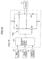
- Fig. 10 is a block diagram for illustrating an arrangement of a driver 16.
- Fig. 11 is a flowchart for illustrating processing operations of an actuating-signals output device 161.
- Fig. 12 is a diagram for illustrating electric currents, which flow in an asymmetric half-bridge circuit 162 depending on the operations of respective switches Q1, Q2.
- Fig. 13 is a diagram for illustrating the value of electric current, which flows in a coil of a vibrator 17 in a map control mode.
- Fig. 14 is a diagram for illustrating the value of electric current, which flows in the vibrator 17 in an adaptive control mode.
- Fig. 15 is a diagram for illustrating a primary frequency component P1, a secondary frequency component S2 and a tertiary component S3 in relation to a low-frequency control signal C3, which the map filter 142 outputs, respectively.
- Fig. 16 is a diagram for illustrating the low-frequency control signal C3, in which the frequency components of the respective orders shown in Fig. 15 are synthesized.
- Fig. 17 is a diagram for illustrating the value of electric current, which flows in the coil of the vibrator 17 when the driver 16 is actuated based on the low-frequency control signal C3.
- the present active vibration insulator comprises the electromagnetic actuator, the control-signals generating means, and the driving means.
- the cyclic control signals which the control-signals generating means generates, can preferably be different from each other between the cases, where the frequencies of the cyclic pulsating signals are a predetermined frequency or less, and where the frequencies of the cyclic pulsating signals are higher than the predetermined frequency.
- the cyclic control signals can preferably comprise a low-frequency control signal, which is produced by synthesizing a primary frequency component and a higher-order frequency component with respect to the frequencies of the cyclic pulsating signals, when the frequencies of the cyclic pulsating signals are a predetermined frequency or less.
- the cyclic control signals can preferably comprise a high-frequency control signal, which is composed of the primary frequency component alone, when the frequencies of the cyclic pulsating signals are higher than the predetermined frequency.
- the present invention will be hereinafter described with reference to an example in which the present active vibration insulator is applied to inhibit the vibrations resulting from an engine from transmitting.
- a higher-order frequency of the vibrations resulting from an engine, a vibration generating source might coincide with the natural frequency of an engine frame. If such is the case, the engine frame might resonate to the higher-order frequency of the vibrations resulting from the engine to eventually vibrate considerably. Consequently, it is preferable to set up the cyclic control signals by taking not only a primary frequency of the vibrations of an engine but also a higher-order frequency of the vibrations into consideration.
- the cyclic control signals are set up by taking a higher-order frequency of the vibrations of an engine into consideration as well, it is possible to inhibit the higher-order frequency vibration from transmitting.
- a higher-order frequency of the vibrations of an engine coincides with the natural frequency of an engine frame, it is possible to inhibit the engine frame from vibrating considerably.
- the engine frame does not resonate to a higher-order frequency of the vibrations of the engine at all.
- the predetermined frequency at which the low-frequency control signal is switched from the high-frequency control signal or vice versa, can be frequencies of the cyclic pulsating signals at which secondary frequency components of the cyclic pulsating signal's frequencies are higher than the natural frequency of an engine frame.
- the predetermined frequency can be higher than 50 Hz, for example, when the natural frequency of an engine frame is 100 Hz.
- the primary frequency component of the low-frequency control signal can preferably comprise a sine-wave signal. That is, the primary frequency component of the low-frequency control signal, a sine-wave signal, has the virtually same waveform as those of primary frequency components of the vibrations of actual engines.
- the present active vibration insulator can more appropriately inhibit the vibrations resulting from a vibration generating source, such as engines, from transmitting. As a result, the present active vibration insulator can produce remarkably high quietness.
- the primary frequency component of the low-frequency control signal can preferably comprise a rectangle-shaped wave signal, which is calculated based on a sine-wave signal.
- the primary frequency component of the low-frequency control signal comprises a rectangle-shaped wave signal, it is possible to enhance the primary frequency component' s ability of inhibiting vibrations from transmitting.
- the primary frequency component of the low-frequency control signal comprises a rectangle-shaped wave signal, it is possible to upgrade the response of the present active vibration insulator. In other words, even when using slow-response electromagnetic actuators, the present active vibration insulator can securely inhibit the vibrations resulting from a vibration generating source, such as engines, from transmitting.
- the high-frequency control signal can preferably comprise a rectangle-shaped wave signal, which is calculated based on the primary frequency component.
- the high-frequency control signal comprising a rectangle-shaped wave signal can enhance the response of the electromagnetic actuator. Consequently, the present active vibration insulator can securely inhibit vibrations from transmitting in high-frequency regions.
- the actuating-signals outputting means actuates the high-side and low-side switches of the asymmetric half-bridge circuit differently depending on whether the cyclic control signals are negative or positive.
- the actuating-signals outputting means can further actuate the high-side and low-side switches of the asymmetric half-bridge circuit differently depending on whether the frequencies of the cyclic pulsating signals are a predetermined frequency or less, or whether they are higher than the predetermined frequency.
- the actuating-signals outputting means can preferably output a turn-off actuating signal to one of the high-side switch and the low-side switch and can preferably output a PWM actuating signal to the other one of them based on the cyclic controls signals when the cyclic control signals are negative and the frequencies of the cyclic pulsating signals are a predetermined frequency or less.
- the actuating-signals outputting means can preferably output a turn-off actuating signal to the high-side switch and the low-side switch when the cyclic control signals are negative and the frequencies of the cyclic pulsating signals are higher than the predetermined frequency.
- the present active vibration insulator when the cyclic control signals are negative, only if the frequencies of the cyclic pulsating signals are a predetermined frequency or less, the present active vibration insulator turns off one of the high-side and low-side switches, and actuates the other one of them by means of pulse-width modulation.
- the present active vibration insulator can control the electromagnetic actuator without letting the value of electric current flowing to the electromagnetic actuator equal to zero. Accordingly, the present active vibration insulator can inhibit the turned-on electricity supply to the electromagnetic actuator from being turned off. Consequently, the present active vibration insulator can suppress the generation of abnormal noises.
- the present active vibration insulator turns off both high-side and low-side switches.
- the frequencies of the cyclic pulsating signals increase, the noises resulting from engines enlarge. Accordingly, when the frequencies of cyclic pulsating signals are high, it does not matter so much if noises generate when the turned-on electricity supply to the electromagnetic actuator is turned off. Consequently, when the frequencies of the cyclic pulsating signals are higher than the predetermined frequency, the present active vibration insulator turns off both high-side and low-side switches in order to make the control for the high-side and low-side switches easier.
- the cyclic-control-signals generating means generates cyclic control signals based on cyclic pulsating signals output from a vibration generating source of a vehicle, as described above, cyclic control signals which actively inhibit a specific part of the vehicle from vibrating.
- the cyclic-control-signals generating means can generate the cyclic control signals differently depending on whether the frequencies of the cyclic pulsating signals are a predetermined frequency or less, or are higher than the predetermined frequency.
- the cyclic-control-signals generating means can preferably calculate the cyclic control signals based a data map stored in advance and driving conditions of the vehicle under vibration control when the frequencies of the cyclic pulsating signals are a predetermined frequency or less.
- the cyclic-control-signals generating means can preferably calculate the cyclic control signals based on an adaptive control method when the frequencies of the cyclic pulsating signals are higher than the predetermined frequency.
- a map control which uses a data map for controlling the electromagnetic actuator, can make the response of the present active vibration insulator favorable.
- map controls are inferior to adaptive controls in view of the adaptability.
- employing an adaptive control method can adaptively inhibit the vibrations, which are affected by various driving conditions, from transmitting.
- Fig. 1 is a block diagram for illustrating the overall arrangement of the active vibration insulator 1.
- the active vibration insulator 1 is an apparatus for actively inhibiting vibrations, which an engine E/G installed to a vehicle generates, from transmitting to parts of the vehicle.
- the active vibration insulator 1 comprises a frequency calculator 11, a mode switcher 12, a driving-condition-signals output device 13, a map controller 14, an adaptive controller 15, a driver 16, a vibrator 17, and an acceleration sensor 18.
- the frequency calculator 11 receives cyclic pulsating signals from a rotary detector (not shown) for detecting the revolutions of the engine E/G. Then, the frequency calculator 11 calculates the frequencies f of the cyclic pulsating signals based on the input cyclic pulsating signals.
- the mode switcher 12 receives the frequencies f of the cyclic pulsating signals which the frequency calculator 11 calculates. Then, the mode switcher 12 judges switching from a map control mode to an adaptive control mode, or vice versa, based on the input frequencies f of the cyclic pulsating signals. The mode switcher 12 selects one or the other of map control mode and adaptive control mode. Note that the mode switching process, map control mode and adaptive control mode will be described in detail later.
- the driving-condition-signals output device 13 is used during the map control mode.
- the driving-condition-signals output device 13 outputs vehicle-driving conditions, such as shift positions of a transmission (e.g., forward "D,” neutral “N,” and reverse “R") and turned-on or off air-conditioner switch, to the map controller 14.
- vehicle-driving conditions such as shift positions of a transmission (e.g., forward "D,” neutral “N,” and reverse “R") and turned-on or off air-conditioner switch, to the map controller 14.
- the map controller 14 operates when the mode switcher 12 switches the adaptive control mode to the map control mode. That is, when the adaptive control mode is switched to the map control mode, the map controller 14 receives the frequencies f of the cyclic pulsating signals, which the frequency calculator 11 calculates, and the driving-condition signals, which the driving-condition-signals output device 13 outputs. Then, the map controller 14 calculates cyclic control signals based on the input frequencies f of the cyclic pulsating signals and the input driving-condition signals as well as a map data stored in a later-described map data storage. Note that the map controller 14 will be described in detail later.
- the adaptive controller 15 operates when the mode switcher 12 switches the map control mode to the adaptive control mode. That is, when the map control mode is switched to the adaptive control mode, the adaptive controller 15 receives the frequencies f of the cyclic pulsating signals, which the frequency calculator 11 calculates, and acceleration signals, which the later-described acceleration sensor 18 detects. Then, the adaptive controller 15 calculates cyclic control signals by means of an adaptive control method, based on the input frequencies f of the cyclic pulsating signals and the input acceleration signals. Note that the adaptive controller 15 will be described in detail later.
- Driver 16 i.e., Driving Means
- the driver 16 actuates the later-described vibrator 17 based on the cyclic signals which the map controller 14 or the adaptive controller 15 outputs.
- the driver 16 receives information on the control mode which the mode switcher 12 selects. That is, when the mode switcher 12 switches the adaptive control mode to the map control mode, the driver 16 actuates the vibrator 17 based on the cyclic control signals which the map controller 14 outputs. On the other hand, when the mode switcher 12 switches the map control mode to the adaptive control mode, the driver 16 actuates the vibrator 17 based on the cyclic control signals which the adaptive controller 15 outputs. Note that the driver 16 will be described in detail later.
- Vibrator 17 i.e., Electromagnetic Actuator
- the vibrator 17 is a solenoid which is installed to an engine mount (not shown).
- the solenoid, the accelerator 17, generates vibrating forces when electricity is supplied to its coil. That is, controlling the electric-current supply to the coil of the solenoid, the vibrator 17, can vary the vibrating forces.
- the vibrations of the engine E/G and the vibrations generated by the vibrator 17 cancel with each other, the vibrations of the engine E/G are not transmitted to the vehicle's side. Note that the vibrator 17 will be described in detail later.
- the acceleration sensor 18 is installed to a fixing part, one of the parts of the engine mount, at which the engine mount is fixed to an engine frame. That is, the acceleration sensor 18 detects vibrations at the fixing part, one of the parts of the engine mount. Specifically, the acceleration sensor 18 detects vibrations which are produced by synthesizing the vibrations of the engine E/G transmitted by way of a transfer system C and the vibrations generated by the vibrator 17. The synthesized vibrations are turned into so-called error signals. Moreover, the acceleration sensor 18 outputs the error signals to the adaptive controller 15.
- FIG. 2 illustrates a partial cross-sectional view of an engine mount 20 equipped with a vibrator.
- the engine mount 20 equipped with a vibrator comprises a cylinder-shaped case 21, an insulation rubber 22, a fixture fitting 24, the vibrator 17, and the acceleration sensor 18.
- the insulation rubber 22 is disposed in the case 21.
- the insulation rubber 22 is fixed to the inner wall of the cover 21 on one of the opposite sides, which is disposed on the vibrator 17's side.
- the insulation rubber 22 is provided with a stopper 22a which is disposed to face one of the opposite ends of the case 21 so as to accommodate an opposite-end installation member of the fixture fitting 24 therein. That is, the insulation rubber 22 is installed to the fixture fitting 24 on the other one of the opposite sides, which is disposed oppositely with respect to the vibrator 17.
- the fixture fitting 24 comprises the installation member, and a fixture shaft 25.
- the fixture shaft 25 is disposed on the opposite side of the insulation rubber 22 with respect to the installation member, and is directed oppositely with respect to the installation member.
- the fixture fitting 24 protrudes out through a through hole 21a, which is formed on one of the opposite sides of the case 21, on the leading-end side of the fixture shaft 25.
- the fixture shaft 25 is fixed to the engine E/G.
- the vibrator 17 comprises a coil (not shown), and a core (not shown).
- the coil is wound in the peripheral direction of the vibrator 17.
- the core is held in the coil, and is disposed about the axial center of the coil.
- the core is reciprocated by making the electric-current supply to the coil variable.
- the reciprocating core generates the vibrating forces.
- the other one of the opposite sides of the case 21 is provided with a fixture shaft 26.
- the fixture shaft 26 is installed to an engine frame E/F.
- the acceleration sensor 18 is fixed to an outer periphery of the case 21. That is, the acceleration sensor 18 meters the vibrations of the case 21 of the engine mount 20 equipped with a vibrator.
- Fig. 3 is a flowchart for illustrating the processing operations of the mode switcher 12.
- the frequencies f of the cyclic pulsating signals which the frequency calculator 11 calculates, are input into the mode switcher 12 at step S1.
- the mode switcher 12 judges whether the input frequencies f of the cyclic pulsating signals are 50 Hz or less at step S2.
- the mode switcher 12 switches the adaptive control mode to the map control mode at step S3.
- the mode switcher 12 switches the map control mode to the adaptive control mode at step S4. That is, when the frequencies f of the cyclic pulsating signals are low frequencies, the adaptive control mode is switched to the map control mode; and, when the frequencies f of the cyclic pulsating signals are high frequencies, the map control mode is switched to the adaptive control mode.
- the mode switcher 12 switches the adaptive control mode to the map control mode when the frequencies f are 50 Hz or less; and switches the map control mode to the adaptive control mode when the frequencies f are higher than 50 Hz.
- the map control mode carried out when the frequencies f are low, actively inhibits the vibrations from transmitting while taking the primary frequency component and higher-order frequency components of the vibrations resulting from the engine E/G into consideration, as described later.
- the adaptive control mode carried out when the frequencies f are high, actively inhibits the vibrations from transmitting while taking only the primary frequency component of the vibrations resulting from the engine E/G into consideration.
- the natural frequency of the engine frame E/F, to which the engine E/G is installed falls in a range of from 80 to 100 Hz approximately. That is, when the frequencies f are 50 Hz or less, the higher-order-frequency components of the vibrations resulting from the engine E/G might coincide with the natural frequency of the engine frame E/F. If they coincide, the resonant action might vibrate the engine frame E/F considerably. On the other hand, when the frequencies f are higher than 50 Hz, the higher-order-frequency components of the vibrations resulting from the engine E/G do not coincide with the natural frequency of the engine frame E/F at all.
- the active vibration insulator 1 carries out the map control, in which only the higher-order-frequency components are taken into consideration, when the frequencies f are 50 Hz or less.
- Fig. 4 is a block diagram for illustrating the arrangement of the map controller 14.
- the map controller 14 comprises a map data storage 141, and a map filter 142.
- the map controller 14 operates when the mode switcher 12 switches the adaptive control mode to the map control mode.
- the map data storage 141 stores filter coefficients, which depend on the frequencies f of the cyclic pulsating signals and driving conditions, in advance.
- the filter coefficients comprise amplitude vales a, which are equivalent to filter coefficient gains, and phase values ⁇ , which are equivalent to filter coefficient phases.
- the frequencies f of the cyclic pulsating signals, which the frequency calculator 11 calculates, and the driving-condition signals, which the driving-condition-signals output device 13 outputs, are input into the map filter 142.
- the map data storage 141 inputs the filter coefficients, which correspond to the input frequencies f of the cyclic pulsating signals and the input driving-condition signals, into the map filter 142.
- the map filter 142 carries out amplitude and phase compensations based on these pieces of input information to generate a cyclic control signal (i.e., a low-frequency control signal) C1. In addition, the map filter 142 outputs the generated low-frequency control signal C1 to the driver 16.
- a cyclic control signal i.e., a low-frequency control signal
- Fig. 5 is a diagram for illustrating a primary frequency component, a secondary frequency component and a tertiary frequency component of the low-frequency control signal C1, which the map filter 142 outputs, respectively.
- Fig. 6 is a diagram for illustrating the low-frequency control signal C1 which is produced by synthesizing the frequency components of the respective orders shown in Fig. 5. Note that Figs. 5 and 6 show the low-frequency control signal C1 for a cyclic pulsating signal whose frequency f is 30 Hz, and represent the maximum value so as to be equal to 1.
- the signal waveform of the low-frequency control signal C1 which is produced by synthesizing the primary, secondary and tertiary frequency components S1, S2 and S3, appears as shown in Fig. 6.
- Fig. 7 is a block diagram for illustrating the arrangement of the adaptive controller 15.
- the adaptive controller 15 herein employs an adaptive control method, which is carried out with a retarded harmonic synthesizer minimum mean squared filter (hereinafter referred to as "DXHS-LMS" filter). Note that the adaptive controller 15 operates when the mode switcher 12 switches the map control mode to the adaptive control mode, as described above.
- DXHS-LMS retarded harmonic synthesizer minimum mean squared filter
- the adaptive controller 15 comprises an adaptive filter 151, a transfer function estimater 152, and a filter coefficient updater 153.
- the frequencies f of the cyclic pulsating signals, which the frequency calculator 11 calculates, and filter coefficients, which the filter coefficient updater 153 updates, are input into the adaptive filter 151.
- the adaptive filter 151 carries out amplitude and phase compensations based on these pieces of input information to generate a cyclic control signal (i.e., a high-frequency control signal) C2.
- the adaptive filter 151 outputs the generated high-frequency control signal C2 to the driver 16.
- the transfer function estimater 152 calculates an estimated value G ⁇ (hereinafter referred to as an "estimated transfer function G' ⁇ ") for an output-controlled system transfer function G of the adaptive filter 151.
- the output-controlled system herein comprises the driver 16, and vibrator 17.
- the filter coefficient adapter 153 updates the filter coefficients with the DXHS-LMS filter based on the output signals of the acceleration sensor 18 and the estimated transfer function G ⁇ .
- the filter coefficients comprise amplitude vales a, which are equivalent to filter coefficient gains, and phase values ⁇ , which are equivalent to filter coefficient phases.
- the adaptive controller 15 updates the filter coefficients so as to make the output signals of the acceleration sensor 18, the errors at an observation point, equal to zero. Moreover, the adaptive controller 15 outputs a high-frequency control signal C2, which is subjected to amplitude and phase compensations, based on the updated filter coefficients.
- Fig. 8 is a diagram for illustrating a high-frequency control signal S1, which the adaptive filter 151 generates, in a form of a sine-wave signal before correction.
- Fig. 9 is a diagram for illustrating the high-frequency control signal C2 which the adaptive filter 151 outputs. Note that Figs. 8 and 9 show the high-frequency control signal C2 for a cyclic pulsating signal whose frequency f is 100 Hz, and represent the maximum value so as to be equal to 1.
- Equation (3) converts before-correction sine-wave signals into rectangle-shaped wave signals.
- Fig. 10 is a block diagram for illustrating the arrangement of the driver 16. As shown in the drawing, the driver 16 comprises an actuating-signals output device 161, and an asymmetric half-bridge circuit 162.
- the actuating-signals output device 161 outputs actuating signals for actuating later-described high-side switch Q1 and low-side switch Q2 based the control mode, which the mode switcher 12 outputs, and the cyclic control signal C1 or C2, which the map controller 14 or adaptive controller 15 outputs. Specifically, the actuating-signals output device 161 outputs gate voltages for actuating the high-side switch Q1 and low-side switch Q2.
- the asymmetric half-bridge circuit 162 makes a so-called H-bridge circuit.
- a first diode D1 is disposed on a first upper arm, and the low-side switch Q2 is disposed on a first lower arm.
- the high-side switch Q1 is disposed on a second upper arm, and a second diode D2 is disposed on a second lower arm.
- both high-side switch Q1 and low-side switch Q2 employ FETs (i.e., field-effect transistors).
- a cathode side of the first diode D1 is connected with a positive-terminal side
- an anode side of the first diode D1 is connected with a drain side of the low-side switch Q2
- a source side of the low-side switch Q2 is connected with a negative-terminal side
- a drain side of the high-side switch Q1 is connected with the positive-terminal side
- a source side of the high-side switch Q1 is connected with a cathode side of the second diode D2
- an anode side of the second diode D2 is connected with the negative-terminal side.
- gate sides of the high-side switch Q1 and low-side switch Q2 are connected with the actuating-signals output device 161. That is, the high-side switch Q1 and low-side switch Q2 are turned on and off depending on the gate voltages which the actuating-signals output device 161 outputs.
- output sides of the asymmetric half-bridge circuit 162 are connected with the vibrator 17. Specifically, an intermediate part between the first diode D1 and the low-side switch Q2, and an intermediate part between the high-side switch Q1 and the second diode D2 are connected with the opposite-end sides of the coil of the solenoid, the vibrator 17, respectively.
- Fig. 11 is a flowchart for illustrating the processing operations of the actuating-signals output device 161.
- the mode switcher 12 first inputs a control mode into the actuating-signals output device 161 at step S11.
- the actuating-signals output device 161 judges whether the input control mode is the map control mode or not at step S12.
- the map controller 14 inputs the low-frequency control signal C1 into the actuating-signals output device 161 at step S13.
- the low-frequency control signal C1 comprises the signal shown in Fig. 6.
- the actuating-signals output device 161 judges whether the low-frequency control signal C1, which the map controller 14 inputs into it, is positive or negative at step S14.
- the actuating-signals output device 161 outputs actuating signals to the high-side switch Q1 and the low-side switch Q2, respectively, at step S15.
- One of the output actuating signals is for turning on the high-side switch Q1, and the other one of them is for actuating the low-side switch Q2 by means of pulse-width modulation with "DUTY,” which is calculated based on the low-frequency control signal C1.
- the actuating-signals output device 161 outputs the aforementioned actuating signals at intervals shown in Fig. 6 other than the intervals designated at "T1" of Fig. 6.
- the actuating-signals output device 161 calculates the absolute value of the low-frequency control signal C1 at step S16. Thereafter, the actuating-signals output device 161 outputs actuating signals to the high-side switch Q1 and the low-side switch Q2, respectively, at step S17.
- One of the output actuating signals is for turning off the high-side switch Q1, and the other one of them is for actuating the low-side switch Q2 by means of pulse-width modulation with "DUTY,” which is calculated based on the absolute value of the low-frequency control signal C1.
- the actuating-signals output device 161 outputs the aforementioned actuating signals at the intervals designated at "T1" of Fig. 6.
- the adaptive controller 15 inputs the high-frequency control signal C2 into the actuating-signals output device 161 at step S18.
- the high-frequency control signal C2 comprises the signal shown in Fig. 9, as described above.
- the actuating-signals output device 161 judges whether the high-frequency control signal C2, which the adaptive controller 15 inputs into it, is positive or negative at step S19.
- the high-frequency control signal C2 is positive, that is, when the answer is "Yes" at step S19
- the actuating-signals output device 161 outputs actuating signals to the high-side switch Q1 and the low-side switch Q2, respectively, at step S20.
- One of the output actuating signals is for turning on the high-side switch Q1, and the other one of them is for actuating the low-side switch Q2 by means of pulse-width modulation with "DUTY,” which is calculated based on the high-frequency control signal C2.
- the actuating-signals output device 161 outputs the aforementioned actuating signals at intervals shown in Fig. 9 other than the intervals designated at "T2" of Fig. 9.
- the actuating-signals output device 161 when the high-frequency control signal C2, which the adaptive controller 15 inputs into the actuating-signals output device 161, is negative, that is, when the answer is "No" at step S19, the actuating-signals output device 161 outputs actuating signals to the high-side switch Q1 and the low-side switch Q2, respectively, at step S21.
- One of the output actuating signals is for turning off the high-side switch Q1, and the other one of them is for turning off the low-side switch Q2.
- the actuating-signals output device 161 outputs the aforementioned actuating signals at the intervals designated at "T2" of Fig. 9.
- Figs. 12 (a), (b) and (c) are diagrams for illustrating electric currents which flow in the asymmetric half-bridge circuit 162 depending on the operations of the high-side switch Q1 and low-side switch Q2.
- Fig. 13 is a diagram for illustrating the values of electric currents, which flow in the coil of the solenoid, the vibrator 17, in the map control mode.
- Fig. 14 is a diagram for illustrating the values of electric currents, which flow in the coil of the solenoid, the vibrator 17, in the adaptive control mode.
- the operations of the asymmetric half-bridge circuit 162 are described for each of the control modes, and for each of the operations of the high-side switch Q1 and low-side switch Q2.
- the operations of the asymmetric half-bridge circuit 162 when the low-frequency control signal C1 is positive are described with reference to Fig. 12 (a) and Fig. 13.
- the high-side switch Q1 is turned on, and the low-side switch Q2 is actuated by means of pulse-width modulation.
- an electric current flows as indicated by the arrows of Fig. 12 (a).
- the electric current flows from the positive-terminal side in the directions toward the high-side switch Q1, the coil of the vibrator 17, the low-side switch Q2 and the negative-terminal side in this order.
- the low-side switch Q2 is actuated by mans of pulse-width modulation, the flowing electric current is proportional to the "DUTY" of pulse-width modulation.
- the value of the electric current flowing in the coil of the vibrator 17 enlarges when the value of the low-frequency control signal C1 is large; and the value of the electric current flowing in the coil of the vibrator 17 diminishes when the value of the low-frequency control signal C1 is small.
- the vibrating forces generated by the vibrator 17 is proportional to the magnitude of the electric current flowing in the coil. Therefore, the vibrator 17 can generate a vibrating force, which is produced while taking the primary frequency component S1, secondary frequency component S2 and tertiary frequency component S3 of the cyclic pulsating signal with the frequency f, when the low-frequency control signal C1 is positive.
- asymmetric half-bridge circuit 162 when the low-frequency control signal C1 is negative are described with reference to Fig. 12 (b) and Fig. 13.
- the high-side switch Q1 is turned off, and the low-side switch Q2 is actuated by means of pulse-width modulation.
- a circumfluent electric current flows as indicated by the arrows of Fig. 12 (b). Specifically, the circumfluent electric current flows around from the second diode D2 in the directions toward the coil of the vibrator 17, the low-side switch Q2, the negative-terminal side and back to the second diode D2 in this order.
- the inductance action of the vibrator 17's coil causes the circumfluent electric current to flow. Therefore, the circumfluent electric current diminishes gradually as time elapses. More specifically, the electric current flowing in the coil of the vibrator 17 decreases, as shown in Fig. 13, at the intervals designated at "T1" of Fig. 13.
- the reason for actuating the low-side switch Q2 by means of pulse-width modulation will be hereinafter described. Compared with the case where both high-side switch Q1 and low-side switch Q2 are turned off, a consequence can be produced that the value of the electric current flowing in the coil of the vibrator 17 is decreased at a lesser reduction rate when the high-side switch Q1 is turned off and the low-side switch Q2 is actuated by means of pulse-width modulation. As a result, actuating the low-side switch Q2 by means of pulse-width modulation can keep the value of the electric current flowing in the coil of the vibrator 17 from being zero.
- keeping the electric-current value from being zero can inhibit the turned-on electricity supply to the coil of the vibrator 17 from being turned off. That is, it is possible to suppress the generation of abnormal noises, which results from turning off the turned-on electricity supply to the coil of the vibrator 17.
- the operations of the asymmetric half-bridge circuit 162 when the high-frequency control signal C2 is positive are described with reference to Fig. 12 (a) and Fig. 14.
- the high-side switch Q1 is turned on, and the low-side switch Q2 is actuated by means of pulse-width modulation.
- the high-frequency control signal C2 comprises a rectangle-shaped wave signal as shown in Fig. 9.
- the low-side switch Q2 is actuated by means of pulse-width modulation depending on constant "DUTY.” That is, when the high-frequency control signal C2 is positive, the electric-current value rises depending on a fixed time constant, as illustrated in Fig. 14. Moreover, converting the high-frequency control signal C2 into the rectangle-shaped wave signal can enlarge the rising rate of the value of the electric current flowing in the coil of the vibrator 17. As a result, the asymmetric half-bridge circuit 162 can cause the vibrator 17 to generate greater vibrating forces.
- asymmetric half-bridge circuit 162 when the high-frequency control signal C2 is negative are described with reference to Fig. 12 (c) and Fig. 14. In this instance, both high-side switch Q1 and low-side switch Q2 are turned off.
- a regenerative electric current flows as indicated by the arrows of Fig. 12 (c). Specifically, the regenerative electric current flows from the negative-terminal side in the directions toward the second diode D2, the coil of the vibrator 17, the first diode D1 and the positive-terminal side in this order. In this occasion, the electric-current value diminishes rapidly to zero depending on a fixed time constant, as illustrated in Fig. 14.
- the vibrator 17 In the map control mode, the vibrator 17 generates vibrating forces based on the low-frequency control signal C1 in which the higher-order frequency components of the cyclic pulsating signal having the frequency f are taken into account. That is, the active vibration insulator 1 can appropriately inhibit the higher-order frequency components of the vibrations resulting from engines from transmitting. As a result, even when the higher-order frequency components of the vibration resulting from engines coincide with the natural frequencies of engine frames, the active vibration insulator 1 can appropriately inhibit the vibrations from transmitting without resonating the higher-order components to the natural frequencies.
- the active vibration insulator 1 controls the electric current flowing in the coil of the vibrator 17 so as not to become zero. That is, the active vibration insulator 1 can inhibit the turned-on electricity supply to the vibrator 17 from being turned off. Therefore, the active vibration insulator 1 can suppress the abnormal noises, which are generated when the turned-on electricity supply to the vibrator 17 is turned off.
- the active vibration insulator 1 actuates the vibrator 17 based on the high-frequency control signal C2 which is corrected to the rectangle-shaped wave signal. Accordingly, the active vibration insulator 1 can exhibit upgraded response, and can cause the vibrator 17 to generate large vibrating forces. Consequently, even when engines operate at high revolutions, the active vibration insulator 1 can appropriately inhibit the vibrations resulting from the engines from transmitting.
- the low-frequency control signal C1 is a signal which comprises sine waves, the primary frequency component S1, secondary frequency component S2 and tertiary frequency component S3 of the cyclic pulsating signal having the frequency f.
- the active vibration insulator 1 can employ another low-frequency control signal C3 as hereinafter described. Note that the active vibration insulator 1 according to the example can produce remarkably high silence because the low-frequency control signal C1 used in the example can cause the vibrator 17 to generate small vibrating forces but can let the vibrator 17 generate vibrating forces which are adapted appropriately to the vibrations generated by engines. On the other hand, the following low-frequency control signal C3 can cause the vibrator 17 to produce larger vibrating forces.
- Fig. 15 is a diagram for illustrating a primary frequency component P1 a secondary frequency component S2 and a tertiary frequency component S3 of the low-frequency control signal C3, which the map filter 142 outputs, respectively.
- Fig. 16 is a diagram for illustrating the low-frequency control signal C3 which is produced by synthesizing the frequency components of the respective orders shown in Fig. 15. Note that Figs. 15 and 16 show the low-frequency control signal C3 for a cyclic pulsating signal whose frequency f is 30 Hz, and represent the maximum value so as to be equal to 1.
- Equation (4) represents the primary frequency component P1 of the low-frequency control signal C3.
- This primary frequency component P1 is a rectangle-shaped wave signal, as shown in Fig. 15.
- Equation (5) represents the secondary frequency component S2 and tertiary frequency component S3 of the low-frequency control signal C3.
- the secondary frequency component S2 and tertiary frequency component S3 are sine-wave signals, as shown in Fig. 15.
- Equation (6) represents the low-frequency control signal C3.
- the low-frequency control signal C3 is a signal which is produced by synthesizing the primary frequency component P1, a signal converted into the rectangle-shaped wave signal, and the secondary and tertiary frequency components S2 and S3, the sine-wave signals. However, note that the maximum value of the low-frequency control signal C3 is set up at a 1 .
- Fig. 17 is a diagram for illustrating the value of the electric current.
- the processing operations of the driver 16 are the same as the above-described processing operations of the driver 16 according to the example. That is, in the map control mode, the driver 16 turns on the high-side switch Q1, and actuates the low-side switch Q2 by means of pulse-width modulation, when the low-frequency control signal C3 is positive. On the other hand, in the adaptive control mode, the driver 16 turns off the high-side switch Q1, and actuates the low-side switch Q2 by means of pulse-width modulation, when the low-frequency control signal C3 is negative.
- the driver 16 when the driver 16 is actuated based on the above-described low-frequency control signal C3, the value of the electric current flowing in the coil of the vibrator 17 appears as illustrated in Fig. 17. Specifically, the electric-current value increases when the low-frequency control signal C3 is positive, and decreases when the low-frequency control signal C3 is negative. Moreover, when the driver 16 is actuated based on the above-described low-frequency control signal C3, the value of the electric current flowing in the vibrator 17 is greater, compared with the case where the driver 16 is actuated based on the low-frequency control signal C1. That is, actuating the driver 16 based on the above-described low-frequency control signal C3 can cause the vibrator 17 to generate larger vibrating forces.
- the active vibration insulator 1 according to this modified version can inhibit the turned-on electricity supply to the vibrator 17 from being turned off. Therefore, the active vibration insulator 1 according to this modified version can suppress the generation of abnormal noises resulting from turning off the turned-on electricity supply to the vibrator 17.
- the actuating signals are adapted to be signals which turn on the high-side switch Q1 and actuate the low-side switch Q2 by means of pulse-width modulation when the low-frequency control signal C1 and high-frequency control signal C2 are positive.
- the actuating signals can be adapted to be signals which actuate the high-side switch Q1 and low-side switch Q2 by means of pulse-width modulation when the low-frequency control signal C1 and high-frequency control signal C2 are positive.
- a PWM signal for the high-side switch Q1 and a PWM signal for the low-side switch Q2 can actuate the high-side switch Q1 and low-side switch Q2 synchronously, or can actuate them in a dephased manner.
- the actuating signals are adapted to be signals which turn off the high-side switch Q1 and actuate the low-side switch Q2 by means of pulse-width modulation when the low-frequency control signal C1 is negative in the map control mode.
- the actuating signals can be adapted to be signals which actuate the high-side switch Q1 by means of pulse-width modulation and turn off the low-side switch Q2 when the low-frequency control signal C1 is negative in the map control mode.
- the active vibration insulator 1 can produce the aforementioned advantages as well.
- the mode switcher 12 switches the control mode from the map control mode to the adaptive control mode, or vice versa, selectively depending on the frequency f of a specific cyclic pulsating signal alone.
- the mode switcher 12 can switch the control mode while taking not only the frequency f but also a vehicle speed into account.
- the mode switcher 12 can switch the control mode from the adaptive control mode to the map control mode when the frequency f is low and the vehicle speed is slow, and can switch the control mode from the map control mode to the adaptive control mode when the frequency f is high and the vehicle speed is fast.
- the frequency f of a specific cyclic pulsating signal, at which the mode switcher 12 switches the control mode from the map control mode to the adaptive control mode, or vice versa is set up at 50 Hz.
- the frequency f can be determined while taking the natural frequencies of other vehicle component parts into consideration in addition to the natural frequencies of engine frames.
- the low-frequency control signal C1 is determined while taking the primary through tertiary frequency components of the cyclic pulsating signal whose frequency is f. However, it is possible to set up the low-frequency control signal C1 while giving consideration to much higher order frequency components. Thus, the active vibration insulator 1 can inhibit much higher vibrations from transmitting.
- An active vibration insulator includes an electromagnetic actuator, a cyclic-control-signals output device, and an electromagnetic-actuator driver.
- the electromagnetic-actuator driver includes an asymmetric half-bridge circuit, and an actuating-signals output device.
- the actuating-signal output device outputs a signal for turning on one of a high-side switch and a low-side switch of the asymmetric half-bridge circuit, and outputs a pulse-width-modulated actuating signal for actuating the other one of them by means of pulse-width modulation based on the cyclic control signals, which the cyclic-control-signals output device outputs, or outputs a pulse-width-modulated actuating signal for actuating both of them by means of pulse-width modulation when the cyclic control signals are positive.
- the actuating-signal output device outputs a signal for turning off one of them, and outputs a pulse-width-modulated actuating signal for actuating the other one of them by means of pulse-width modulation when the cyclic control signals are negative.
Abstract
Description
- The present invention relates to an active vibration insulator, especially, an active vibration controller for actively inhibiting the vibrations of vibration generating sources, such as vehicle engines, from transmitting.
- Japanese Unexamined Patent Publication (KOKAI) No. 2001-117,644, for example, discloses a conventional active vibration insulator which is equipped with an electromagnet. The electromagnet is disposed inside a so-called engine mount, and generates vibrating forces to inhibit the vibrations of engines from transmitting. Specifically, the vibrations of engines are inhibited from transmitting by controlling the turning on and off of electric supply to the electromagnet depending on the vibrations of engines.
- However, the conventional active vibration insulator might possibly generate abnormal noises when turned-on electricity supply to the electromagnet is turned off.
- The present invention has been developed in view of the aforementioned circumstance. It is therefore an object of the present invention to provide an active vibration insulator which can suppress the generation of abnormal noises, for instance, by inhibiting turned-on electricity supply to electromagnetic actuators, such as electromagnets, from being turned off.
- An active vibration insulator according to the present invention comprises an electromagnetic actuator for generating vibrating forces by making an electric-current supply variable; means for generating cyclic control signals based on cyclic pulsating signals output from a vibration generating source of a vehicle, the cyclic control signals actively inhibiting a specific part of the vehicle from vibrating; and means for driving the electromagnetic actuator by making the electric-current supply to the electromagnetic actuator variable based on the cyclic control signals.
- One of the present active vibration insulator's characteristic arrangements is the electromagnetic-actuator-driving means comprising an asymmetric half-bridge circuit and means for outputting actuating signals. Note herein that the asymmetric half-bridge circuit is a circuit which comprises a high-side switch connected with a positive-terminal side of the electromagnetic actuator, and a low-side switch connected with a negative-terminal side of the electromagnetic actuator and disposed asymmetrically with respect to the high-side switch. For example, the asymmetric half-bridge circuit can be an H-bridge circuit. The H-bridge circuit is a circuit which comprises paired arms, a high-side switch disposed on an upper side of one of the paired arms, and a low-side switch disposed on a lower side of the other one of the paired arms. Moreover, the H-bridge circuit further comprises diodes, one of which is disposed on a lower side of the one of the paired arms and another one of which is disposed on an upper side of the other one of the paired arms, so as to flow an electric current in the paired arms only when adversely flowing (or regenerating) the electric current in the H-bridge circuit. In addition, an electric current is flowed to the electromagnetic actuator by turning on or off the high-side switch and the low-side switch.
- Moreover, the actuating-signals outputting means outputs actuating signals, which differ from each other when the cyclic control signals are positive or negative, respectively. Specifically, the actuating-signals outputting means outputs a turn-on actuating signal to one of the high-side switch and the low-side switch, and outputs a pulse-width-modulated (hereinafter abbreviated to as "PWM") actuating signal to the other one of them based on the cyclic control signals when the cyclic control signals are positive. Alternatively, the actuating-signals outputting means outputs a PWM actuating signal to both of the high-side switch and the low-side switch based on the cyclic control signals when the cyclic control signals are positive. On the other hand, the actuating-signals outputting means outputs a turn-off actuating signal to one of the high-side switch and the low-side switch, and outputs a PWM actuating signal to the other one of them based on the cyclic control signals when the cyclic control signals are negative.
- That is, the actuating-signals outputting means operates so as to increase an electric current flowing to the electromagnetic actuator when the cyclic control signals are positive. On the other hand, the actuating-signals outputting means operates so as to decrease an electric current flowing to the electromagnetic actuator when the cyclic control signals are negative.
- The present active vibration insulator turns off one of the high-side switch and the low-side switch, and actuates the other one of them with a PWM actuating signal based on the cyclic control signals. When both high-side switch and low-side switch are turned off, an electric current flowing to the electromagnetic actuator might possibly decrease rapidly so that the electric-current value might equal to zero. However, when one of the high-side switch and the low-side switch is turned off and the other one of them is actuated with a PWM actuating signal as the present active vibration insulator carries out, an electric current flowing to the electromagnetic actuator decreases with a reduced decrement rate. Therefore, it is possible to control the electromagnetic actuator without letting the value of electric current flowing to the electromagnetic actuator equal to zero. Accordingly, the present active vibration insulator can inhibit the turned-on electricity supply to the electromagnetic actuator from being turned off. Consequently, the present active vibration insulator can suppress the generation of abnormal noises.
- A more complete appreciation of the present invention and many of its advantages will be readily obtained as the same becomes better understood by reference to the following detailed description when considered in connection with the accompanying drawings and detailed specification, all of which forms a part of the disclosure.
- Fig. 1 is a schematic diagram for illustrating an overall arrangement of an
active vibration insulator 1 according to an example of the present invention. - Fig. 2 illustrates a partially cross-sectional view of an
engine mount 20 equipped with a vibrator. - Fig. 3 is a flowchart for illustrating processing operations of a
mode switcher 12. - Fig. 4 is a block diagram for illustrating an arrangement of a
map controller 14. - Fig. 5 is a diagram for illustrating a primary frequency component S1, a secondary frequency component S2 and a tertiary component S3 in relation to a low-frequency control signal C1, which a map filter 142 outputs, respectively.
- Fig. 6 is a diagram for illustrating the low-frequency control signal C1, in which the frequency components of the respective orders shown in Fig. 5 are synthesized.
- Fig. 7 is a block diagram for illustrating an arrangement of an
adaptive controller 15. - Fig. 8 is a diagram for illustrating a high-frequency control signal, which an
adaptive filter 151 generates, and which is put in a state of sine wave before correction. - Fig. 9 is a diagram for illustrating a high-frequency control signal C2, which the
adaptive filter 151 outputs. - Fig. 10 is a block diagram for illustrating an arrangement of a
driver 16. - Fig. 11 is a flowchart for illustrating processing operations of an actuating-
signals output device 161. - Fig. 12 is a diagram for illustrating electric currents, which flow in an asymmetric half-
bridge circuit 162 depending on the operations of respective switches Q1, Q2. - Fig. 13 is a diagram for illustrating the value of electric current, which flows in a coil of a
vibrator 17 in a map control mode. - Fig. 14 is a diagram for illustrating the value of electric current, which flows in the
vibrator 17 in an adaptive control mode. - Fig. 15 is a diagram for illustrating a primary frequency component P1, a secondary frequency component S2 and a tertiary component S3 in relation to a low-frequency control signal C3, which the map filter 142 outputs, respectively.
- Fig. 16 is a diagram for illustrating the low-frequency control signal C3, in which the frequency components of the respective orders shown in Fig. 15 are synthesized.
- Fig. 17 is a diagram for illustrating the value of electric current, which flows in the coil of the
vibrator 17 when thedriver 16 is actuated based on the low-frequency control signal C3. - Having generally described the present invention, a further understanding can be obtained by reference to the specific preferred embodiments which are provided herein for the purpose of illustration only and not intended to limit the scope of the appended claims.
- The present invention will be hereinafter described in detail while naming its specific embodiments. As described above, the present active vibration insulator comprises the electromagnetic actuator, the control-signals generating means, and the driving means.
- Note that the cyclic control signals, which the control-signals generating means generates, can preferably be different from each other between the cases, where the frequencies of the cyclic pulsating signals are a predetermined frequency or less, and where the frequencies of the cyclic pulsating signals are higher than the predetermined frequency. Specifically, the cyclic control signals can preferably comprise a low-frequency control signal, which is produced by synthesizing a primary frequency component and a higher-order frequency component with respect to the frequencies of the cyclic pulsating signals, when the frequencies of the cyclic pulsating signals are a predetermined frequency or less. Moreover, the cyclic control signals can preferably comprise a high-frequency control signal, which is composed of the primary frequency component alone, when the frequencies of the cyclic pulsating signals are higher than the predetermined frequency.
- The present invention will be hereinafter described with reference to an example in which the present active vibration insulator is applied to inhibit the vibrations resulting from an engine from transmitting. Even when the present active vibration insulator is applied to only inhibit a primary frequency component of the vibrations resulting from an engine from transmitting, a higher-order frequency of the vibrations resulting from an engine, a vibration generating source, might coincide with the natural frequency of an engine frame. If such is the case, the engine frame might resonate to the higher-order frequency of the vibrations resulting from the engine to eventually vibrate considerably. Consequently, it is preferable to set up the cyclic control signals by taking not only a primary frequency of the vibrations of an engine but also a higher-order frequency of the vibrations into consideration. That is, when the cyclic control signals are set up by taking a higher-order frequency of the vibrations of an engine into consideration as well, it is possible to inhibit the higher-order frequency vibration from transmitting. Thus, even when a higher-order frequency of the vibrations of an engine coincides with the natural frequency of an engine frame, it is possible to inhibit the engine frame from vibrating considerably. However, when a primary frequency component of the vibrations of an engine is higher than the natural frequency of an engine frame, the engine frame does not resonate to a higher-order frequency of the vibrations of the engine at all. Therefore, in the aforementioned preferable instance, the predetermined frequency, at which the low-frequency control signal is switched from the high-frequency control signal or vice versa, can be frequencies of the cyclic pulsating signals at which secondary frequency components of the cyclic pulsating signal's frequencies are higher than the natural frequency of an engine frame. Specifically, the predetermined frequency can be higher than 50 Hz, for example, when the natural frequency of an engine frame is 100 Hz.
- Further, the primary frequency component of the low-frequency control signal can preferably comprise a sine-wave signal. That is, the primary frequency component of the low-frequency control signal, a sine-wave signal, has the virtually same waveform as those of primary frequency components of the vibrations of actual engines. Thus, the present active vibration insulator can more appropriately inhibit the vibrations resulting from a vibration generating source, such as engines, from transmitting. As a result, the present active vibration insulator can produce remarkably high quietness.
- Furthermore, the primary frequency component of the low-frequency control signal can preferably comprise a rectangle-shaped wave signal, which is calculated based on a sine-wave signal. When the primary frequency component of the low-frequency control signal comprises a rectangle-shaped wave signal, it is possible to enhance the primary frequency component' s ability of inhibiting vibrations from transmitting. Moreover, when the primary frequency component of the low-frequency control signal comprises a rectangle-shaped wave signal, it is possible to upgrade the response of the present active vibration insulator. In other words, even when using slow-response electromagnetic actuators, the present active vibration insulator can securely inhibit the vibrations resulting from a vibration generating source, such as engines, from transmitting.
- In addition, the high-frequency control signal can preferably comprise a rectangle-shaped wave signal, which is calculated based on the primary frequency component. In a region where the frequencies of vibrations resulting from a vibration generating source, such as engines, are high, the electromagnetic actuator are required to exhibit high response. Accordingly, the high-frequency control signal comprising a rectangle-shaped wave signal can enhance the response of the electromagnetic actuator. Consequently, the present active vibration insulator can securely inhibit vibrations from transmitting in high-frequency regions.
- As described above, the actuating-signals outputting means actuates the high-side and low-side switches of the asymmetric half-bridge circuit differently depending on whether the cyclic control signals are negative or positive. Note herein that the actuating-signals outputting means can further actuate the high-side and low-side switches of the asymmetric half-bridge circuit differently depending on whether the frequencies of the cyclic pulsating signals are a predetermined frequency or less, or whether they are higher than the predetermined frequency.
- Specifically, the actuating-signals outputting means can preferably output a turn-off actuating signal to one of the high-side switch and the low-side switch and can preferably output a PWM actuating signal to the other one of them based on the cyclic controls signals when the cyclic control signals are negative and the frequencies of the cyclic pulsating signals are a predetermined frequency or less. On the other hand, the actuating-signals outputting means can preferably output a turn-off actuating signal to the high-side switch and the low-side switch when the cyclic control signals are negative and the frequencies of the cyclic pulsating signals are higher than the predetermined frequency.
- That is, when the cyclic control signals are negative, only if the frequencies of the cyclic pulsating signals are a predetermined frequency or less, the present active vibration insulator turns off one of the high-side and low-side switches, and actuates the other one of them by means of pulse-width modulation. When one of the high-side and low-side switches is thus turned off and the other one of them is thus actuated by means of pulse-width modulation, an electric current flowing to the electromagnetic actuator decreases with a reduced decrement rate. Therefore, the present active vibration insulator can control the electromagnetic actuator without letting the value of electric current flowing to the electromagnetic actuator equal to zero. Accordingly, the present active vibration insulator can inhibit the turned-on electricity supply to the electromagnetic actuator from being turned off. Consequently, the present active vibration insulator can suppress the generation of abnormal noises.
- On the other hand, when the frequencies of the cyclic pulsating signals are higher than the predetermined frequency, the present active vibration insulator turns off both high-side and low-side switches. As the frequencies of the cyclic pulsating signals increase, the noises resulting from engines enlarge. Accordingly, when the frequencies of cyclic pulsating signals are high, it does not matter so much if noises generate when the turned-on electricity supply to the electromagnetic actuator is turned off. Consequently, when the frequencies of the cyclic pulsating signals are higher than the predetermined frequency, the present active vibration insulator turns off both high-side and low-side switches in order to make the control for the high-side and low-side switches easier.
- The cyclic-control-signals generating means generates cyclic control signals based on cyclic pulsating signals output from a vibration generating source of a vehicle, as described above, cyclic control signals which actively inhibit a specific part of the vehicle from vibrating. The cyclic-control-signals generating means can generate the cyclic control signals differently depending on whether the frequencies of the cyclic pulsating signals are a predetermined frequency or less, or are higher than the predetermined frequency.
- Specifically, the cyclic-control-signals generating means can preferably calculate the cyclic control signals based a data map stored in advance and driving conditions of the vehicle under vibration control when the frequencies of the cyclic pulsating signals are a predetermined frequency or less. On the other hand, the cyclic-control-signals generating means can preferably calculate the cyclic control signals based on an adaptive control method when the frequencies of the cyclic pulsating signals are higher than the predetermined frequency.
- When the frequencies of the cyclic pulsating signals are a predetermined frequency or less, employing a map control, which uses a data map for controlling the electromagnetic actuator, can make the response of the present active vibration insulator favorable. Note that map controls are inferior to adaptive controls in view of the adaptability. However, since there are few signals relating to other than engines when engine revolutions are low, it is possible to adequately inhibit the vibrations resulting from engines from transmitting. On the contrary, enhancing the response can securely suppress the vibrations resulting from engines. On the other hand, when the frequencies of the cyclic pulsating signals are higher than the predetermined frequency, employing an adaptive control method can adaptively inhibit the vibrations, which are affected by various driving conditions, from transmitting.
- Hereinafter, the present active vibration insulator will be described in detail while naming specific examples.
- An overall arrangement of an
active vibration insulator 1 according to an example of the present invention will be described with reference to Fig. 1. Fig. 1 is a block diagram for illustrating the overall arrangement of theactive vibration insulator 1. Theactive vibration insulator 1 is an apparatus for actively inhibiting vibrations, which an engine E/G installed to a vehicle generates, from transmitting to parts of the vehicle. As shown in the drawing, theactive vibration insulator 1 comprises afrequency calculator 11, amode switcher 12, a driving-condition-signals output device 13, amap controller 14, anadaptive controller 15, adriver 16, avibrator 17, and anacceleration sensor 18. - The
frequency calculator 11 receives cyclic pulsating signals from a rotary detector (not shown) for detecting the revolutions of the engine E/G. Then, thefrequency calculator 11 calculates the frequencies f of the cyclic pulsating signals based on the input cyclic pulsating signals. - The
mode switcher 12 receives the frequencies f of the cyclic pulsating signals which thefrequency calculator 11 calculates. Then, themode switcher 12 judges switching from a map control mode to an adaptive control mode, or vice versa, based on the input frequencies f of the cyclic pulsating signals. Themode switcher 12 selects one or the other of map control mode and adaptive control mode. Note that the mode switching process, map control mode and adaptive control mode will be described in detail later. - The driving-condition-
signals output device 13 is used during the map control mode. The driving-condition-signals output device 13 outputs vehicle-driving conditions, such as shift positions of a transmission (e.g., forward "D," neutral "N," and reverse "R") and turned-on or off air-conditioner switch, to themap controller 14. - The
map controller 14 operates when themode switcher 12 switches the adaptive control mode to the map control mode. That is, when the adaptive control mode is switched to the map control mode, themap controller 14 receives the frequencies f of the cyclic pulsating signals, which thefrequency calculator 11 calculates, and the driving-condition signals, which the driving-condition-signals output device 13 outputs. Then, themap controller 14 calculates cyclic control signals based on the input frequencies f of the cyclic pulsating signals and the input driving-condition signals as well as a map data stored in a later-described map data storage. Note that themap controller 14 will be described in detail later. - On the other hand, the
adaptive controller 15 operates when themode switcher 12 switches the map control mode to the adaptive control mode. That is, when the map control mode is switched to the adaptive control mode, theadaptive controller 15 receives the frequencies f of the cyclic pulsating signals, which thefrequency calculator 11 calculates, and acceleration signals, which the later-describedacceleration sensor 18 detects. Then, theadaptive controller 15 calculates cyclic control signals by means of an adaptive control method, based on the input frequencies f of the cyclic pulsating signals and the input acceleration signals. Note that theadaptive controller 15 will be described in detail later. - The
driver 16 actuates the later-describedvibrator 17 based on the cyclic signals which themap controller 14 or theadaptive controller 15 outputs. Thedriver 16 receives information on the control mode which themode switcher 12 selects. That is, when themode switcher 12 switches the adaptive control mode to the map control mode, thedriver 16 actuates thevibrator 17 based on the cyclic control signals which themap controller 14 outputs. On the other hand, when themode switcher 12 switches the map control mode to the adaptive control mode, thedriver 16 actuates thevibrator 17 based on the cyclic control signals which theadaptive controller 15 outputs. Note that thedriver 16 will be described in detail later. - The
vibrator 17 is a solenoid which is installed to an engine mount (not shown). The solenoid, theaccelerator 17, generates vibrating forces when electricity is supplied to its coil. That is, controlling the electric-current supply to the coil of the solenoid, thevibrator 17, can vary the vibrating forces. Moreover, when the vibrations of the engine E/G and the vibrations generated by thevibrator 17 cancel with each other, the vibrations of the engine E/G are not transmitted to the vehicle's side. Note that thevibrator 17 will be described in detail later. - The
acceleration sensor 18 is installed to a fixing part, one of the parts of the engine mount, at which the engine mount is fixed to an engine frame. That is, theacceleration sensor 18 detects vibrations at the fixing part, one of the parts of the engine mount. Specifically, theacceleration sensor 18 detects vibrations which are produced by synthesizing the vibrations of the engine E/G transmitted by way of a transfer system C and the vibrations generated by thevibrator 17. The synthesized vibrations are turned into so-called error signals. Moreover, theacceleration sensor 18 outputs the error signals to theadaptive controller 15. - Subsequently, a detailed arrangement of an engine mount equipped with a vibrator and comprising the
vibrator 17 andacceleration sensor 18 will be hereinafter described with reference to Fig. 2. Fig. 2 illustrates a partial cross-sectional view of anengine mount 20 equipped with a vibrator. As shown in the drawing, theengine mount 20 equipped with a vibrator comprises a cylinder-shapedcase 21, aninsulation rubber 22, a fixture fitting 24, thevibrator 17, and theacceleration sensor 18. Theinsulation rubber 22 is disposed in thecase 21. Moreover, theinsulation rubber 22 is fixed to the inner wall of thecover 21 on one of the opposite sides, which is disposed on thevibrator 17's side. In addition, theinsulation rubber 22 is provided with astopper 22a which is disposed to face one of the opposite ends of thecase 21 so as to accommodate an opposite-end installation member of the fixture fitting 24 therein. That is, theinsulation rubber 22 is installed to the fixture fitting 24 on the other one of the opposite sides, which is disposed oppositely with respect to thevibrator 17. - The fixture fitting 24 comprises the installation member, and a
fixture shaft 25. Thefixture shaft 25 is disposed on the opposite side of theinsulation rubber 22 with respect to the installation member, and is directed oppositely with respect to the installation member. Moreover, the fixture fitting 24 protrudes out through a throughhole 21a, which is formed on one of the opposite sides of thecase 21, on the leading-end side of thefixture shaft 25. In addition, thefixture shaft 25 is fixed to the engine E/G. - The
vibrator 17 comprises a coil (not shown), and a core (not shown). The coil is wound in the peripheral direction of thevibrator 17. The core is held in the coil, and is disposed about the axial center of the coil. Moreover, the core is reciprocated by making the electric-current supply to the coil variable. The reciprocating core generates the vibrating forces. In addition, the other one of the opposite sides of thecase 21 is provided with afixture shaft 26. Thefixture shaft 26 is installed to an engine frame E/F. - The
acceleration sensor 18 is fixed to an outer periphery of thecase 21. That is, theacceleration sensor 18 meters the vibrations of thecase 21 of theengine mount 20 equipped with a vibrator. - Firstly, the processing operations of the above-described
mode switcher 12 will be hereinafter described with reference to Fig. 3. Fig. 3 is a flowchart for illustrating the processing operations of themode switcher 12. As shown in the drawing, the frequencies f of the cyclic pulsating signals, which thefrequency calculator 11 calculates, are input into themode switcher 12 at step S1. Next, themode switcher 12 judges whether the input frequencies f of the cyclic pulsating signals are 50 Hz or less at step S2. When the frequencies f of the cyclic pulsating signals are 50 Hz or less, themode switcher 12 switches the adaptive control mode to the map control mode at step S3. On the other hand, when the frequencies f of the cyclic pulsating signals are higher than 50 Hz, themode switcher 12 switches the map control mode to the adaptive control mode at step S4. That is, when the frequencies f of the cyclic pulsating signals are low frequencies, the adaptive control mode is switched to the map control mode; and, when the frequencies f of the cyclic pulsating signals are high frequencies, the map control mode is switched to the adaptive control mode. - The reasons for setting up the frequency, at which the control modes are switched, to 50 Hz will be hereinafter described briefly. As described above, the
mode switcher 12 switches the adaptive control mode to the map control mode when the frequencies f are 50 Hz or less; and switches the map control mode to the adaptive control mode when the frequencies f are higher than 50 Hz. Note that the map control mode, carried out when the frequencies f are low, actively inhibits the vibrations from transmitting while taking the primary frequency component and higher-order frequency components of the vibrations resulting from the engine E/G into consideration, as described later. On the other hand, the adaptive control mode, carried out when the frequencies f are high, actively inhibits the vibrations from transmitting while taking only the primary frequency component of the vibrations resulting from the engine E/G into consideration. - However, the natural frequency of the engine frame E/F, to which the engine E/G is installed, falls in a range of from 80 to 100 Hz approximately. That is, when the frequencies f are 50 Hz or less, the higher-order-frequency components of the vibrations resulting from the engine E/G might coincide with the natural frequency of the engine frame E/F. If they coincide, the resonant action might vibrate the engine frame E/F considerably. On the other hand, when the frequencies f are higher than 50 Hz, the higher-order-frequency components of the vibrations resulting from the engine E/G do not coincide with the natural frequency of the engine frame E/F at all.
- That is, unless the engine frame E/F resonates to the higher-order-frequency components of the vibrations resulting from the engine E/G, the
active vibration insulator 1 carries out the map control, in which only the higher-order-frequency components are taken into consideration, when the frequencies f are 50 Hz or less. - Secondly, the detailed arrangement of the
map controller 14 will be hereinafter described with reference to Fig. 4. Fig. 4 is a block diagram for illustrating the arrangement of themap controller 14. As illustrated in the drawing, themap controller 14 comprises amap data storage 141, and amap filter 142. As described above, themap controller 14 operates when themode switcher 12 switches the adaptive control mode to the map control mode. - The
map data storage 141 stores filter coefficients, which depend on the frequencies f of the cyclic pulsating signals and driving conditions, in advance. Here, the filter coefficients comprise amplitude vales a, which are equivalent to filter coefficient gains, and phase values φ, which are equivalent to filter coefficient phases. The frequencies f of the cyclic pulsating signals, which thefrequency calculator 11 calculates, and the driving-condition signals, which the driving-condition-signals output device 13 outputs, are input into themap filter 142. Moreover, themap data storage 141 inputs the filter coefficients, which correspond to the input frequencies f of the cyclic pulsating signals and the input driving-condition signals, into themap filter 142. Themap filter 142 carries out amplitude and phase compensations based on these pieces of input information to generate a cyclic control signal (i.e., a low-frequency control signal) C1. In addition, themap filter 142 outputs the generated low-frequency control signal C1 to thedriver 16. - The low-frequency control signal C1, which the
map filter 142 generates, will be hereinafter described with reference to Figs. 5 and 6. Fig. 5 is a diagram for illustrating a primary frequency component, a secondary frequency component and a tertiary frequency component of the low-frequency control signal C1, which themap filter 142 outputs, respectively. Fig. 6 is a diagram for illustrating the low-frequency control signal C1 which is produced by synthesizing the frequency components of the respective orders shown in Fig. 5. Note that Figs. 5 and 6 show the low-frequency control signal C1 for a cyclic pulsating signal whose frequency f is 30 Hz, and represent the maximum value so as to be equal to 1. - The low-frequency control signal C1, which the
map filter 142 generates, is calculated based on following equation (1). Since the order k is herein limited up to tertiary, K=3 in equation (1). Moreover, as expressed in equation (1), the low-frequency control signal C1 is a signal which is produced by synthesizing a primary frequency component S1, a secondary frequency component S2 and a tertiary component S3 of a cyclic pulsating signal with a frequency f. In addition, the primary frequency component S1, secondary frequency component S2 and tertiary component S3 are herein sine-wave signals, respectively. Note that the "offset" is a value which is set up in advance depending on a vehicle.
- a(n): Amplitude Value (or Filter Coefficient Gain)
- φ (n): Phase Value (or Filter Coefficient Phase)
- ω: Metered Angular Frequency
- ΔT: Sampling Cycle
- N: Sampling Number (time)
- k: Frequency Order (k=1, 2, 3)
- offset: Offset for Output Calculated Value
- Thus, the signal waveforms of the primary, secondary and tertiary frequency components S1, S2 and S3 of the low-frequency control signal C1, which is produced based on equation (1), appear as shown in Fig. 5. Moreover, the signal waveform of the low-frequency control signal C1, which is produced by synthesizing the primary, secondary and tertiary frequency components S1, S2 and S3, appears as shown in Fig. 6.
- Thirdly, the detailed arrangement of the
adaptive controller 15 will be hereinafter described with reference to Fig. 7. Fig. 7 is a block diagram for illustrating the arrangement of theadaptive controller 15. Theadaptive controller 15 herein employs an adaptive control method, which is carried out with a retarded harmonic synthesizer minimum mean squared filter (hereinafter referred to as "DXHS-LMS" filter). Note that theadaptive controller 15 operates when themode switcher 12 switches the map control mode to the adaptive control mode, as described above. - As illustrated in Fig. 7, the
adaptive controller 15 comprises anadaptive filter 151, atransfer function estimater 152, and afilter coefficient updater 153. The frequencies f of the cyclic pulsating signals, which thefrequency calculator 11 calculates, and filter coefficients, which thefilter coefficient updater 153 updates, are input into theadaptive filter 151. Moreover, theadaptive filter 151 carries out amplitude and phase compensations based on these pieces of input information to generate a cyclic control signal (i.e., a high-frequency control signal) C2. In addition, theadaptive filter 151 outputs the generated high-frequency control signal C2 to thedriver 16. - The
transfer function estimater 152 calculates an estimated value G^ (hereinafter referred to as an "estimated transfer function G'^") for an output-controlled system transfer function G of theadaptive filter 151. The output-controlled system herein comprises thedriver 16, andvibrator 17. Thefilter coefficient adapter 153 updates the filter coefficients with the DXHS-LMS filter based on the output signals of theacceleration sensor 18 and the estimated transfer function G^. Here, the filter coefficients comprise amplitude vales a, which are equivalent to filter coefficient gains, and phase values φ, which are equivalent to filter coefficient phases. - That is, the
adaptive controller 15 updates the filter coefficients so as to make the output signals of theacceleration sensor 18, the errors at an observation point, equal to zero. Moreover, theadaptive controller 15 outputs a high-frequency control signal C2, which is subjected to amplitude and phase compensations, based on the updated filter coefficients. - The high-frequency control signal C2, which the
adaptive filter 151 generates, will be hereinafter described with reference to Figs. 8 and 9. Fig. 8 is a diagram for illustrating a high-frequency control signal S1, which theadaptive filter 151 generates, in a form of a sine-wave signal before correction. Fig. 9 is a diagram for illustrating the high-frequency control signal C2 which theadaptive filter 151 outputs. Note that Figs. 8 and 9 show the high-frequency control signal C2 for a cyclic pulsating signal whose frequency f is 100 Hz, and represent the maximum value so as to be equal to 1. - The before-correction high-frequency control signal S1, which the
adaptive filter 151 generates, is first calculated based on following equation (2). Since the order k is herein limited to primary alone, K=1 in equation (2) . That is, the before-correction high-frequency control signal S1 is a sine-wave signal comprising a primary frequency component S1 of a cyclic pulsating signal with a frequency f alone. The waveform of the before-correction high-frequency control signal S1 is a sine wave which appears as shown in Fig. 8.
- Subsequently, the thus calculated before-correction high-frequency control signal S1 is subjected to correction in accordance with equation (3). The high-frequency control signal C2, which has undergone the correction, is a signal to be output to the
driver 16. That is, Equation (3) converts before-correction sine-wave signals into rectangle-shaped wave signals. The after-correction high-frequency control signal C2 appears as a rectangle-shaped wave, as shown in Fig. 9.
- Fourthly, the detailed arrangement of the
driver 16 will be hereinafter described with reference to Fig. 10. Fig. 10 is a block diagram for illustrating the arrangement of thedriver 16. As shown in the drawing, thedriver 16 comprises an actuating-signals output device 161, and an asymmetric half-bridge circuit 162. - The actuating-
signals output device 161 outputs actuating signals for actuating later-described high-side switch Q1 and low-side switch Q2 based the control mode, which themode switcher 12 outputs, and the cyclic control signal C1 or C2, which themap controller 14 oradaptive controller 15 outputs. Specifically, the actuating-signals output device 161 outputs gate voltages for actuating the high-side switch Q1 and low-side switch Q2. - The asymmetric half-
bridge circuit 162 makes a so-called H-bridge circuit. A first diode D1 is disposed on a first upper arm, and the low-side switch Q2 is disposed on a first lower arm. The high-side switch Q1 is disposed on a second upper arm, and a second diode D2 is disposed on a second lower arm. Here, both high-side switch Q1 and low-side switch Q2 employ FETs (i.e., field-effect transistors). - Specifically, a cathode side of the first diode D1 is connected with a positive-terminal side, an anode side of the first diode D1 is connected with a drain side of the low-side switch Q2, and a source side of the low-side switch Q2 is connected with a negative-terminal side. Moreover, a drain side of the high-side switch Q1 is connected with the positive-terminal side, a source side of the high-side switch Q1 is connected with a cathode side of the second diode D2, and an anode side of the second diode D2 is connected with the negative-terminal side. Note that gate sides of the high-side switch Q1 and low-side switch Q2 are connected with the actuating-
signals output device 161. That is, the high-side switch Q1 and low-side switch Q2 are turned on and off depending on the gate voltages which the actuating-signals output device 161 outputs. - In addition, output sides of the asymmetric half-
bridge circuit 162 are connected with thevibrator 17. Specifically, an intermediate part between the first diode D1 and the low-side switch Q2, and an intermediate part between the high-side switch Q1 and the second diode D2 are connected with the opposite-end sides of the coil of the solenoid, thevibrator 17, respectively. - The processing operations of the
driver 16 arranged as described above will be hereinafter described with reference to Figs. 11 through 14. - The processing operations of the actuating-
signals output device 161 are first described with reference to Fig. 11. Fig. 11 is a flowchart for illustrating the processing operations of the actuating-signals output device 161. - As illustrated in Fig. 11, the
mode switcher 12 first inputs a control mode into the actuating-signals output device 161 at step S11. Next, the actuating-signals output device 161 judges whether the input control mode is the map control mode or not at step S12. When the input control mode is the map control mode, that is, when the answer is "Yes" at step S12, themap controller 14 inputs the low-frequency control signal C1 into the actuating-signals output device 161 at step S13. The low-frequency control signal C1 comprises the signal shown in Fig. 6. - Subsequently, the actuating-
signals output device 161 judges whether the low-frequency control signal C1, which themap controller 14 inputs into it, is positive or negative at step S14. When the low-frequency control signal C1 is positive, that is, when the answer is "Yes" at step S14, the actuating-signals output device 161 outputs actuating signals to the high-side switch Q1 and the low-side switch Q2, respectively, at step S15. One of the output actuating signals is for turning on the high-side switch Q1, and the other one of them is for actuating the low-side switch Q2 by means of pulse-width modulation with "DUTY," which is calculated based on the low-frequency control signal C1. Specifically, the actuating-signals output device 161 outputs the aforementioned actuating signals at intervals shown in Fig. 6 other than the intervals designated at "T1" of Fig. 6. - On the other hand, when the low-frequency control signal C1, which the
map controller 14 inputs into the actuating-signals output device 161, is negative, that is, when the answer is "No" at step S14, the actuating-signals output device 161 calculates the absolute value of the low-frequency control signal C1 at step S16. Thereafter, the actuating-signals output device 161 outputs actuating signals to the high-side switch Q1 and the low-side switch Q2, respectively, at step S17. One of the output actuating signals is for turning off the high-side switch Q1, and the other one of them is for actuating the low-side switch Q2 by means of pulse-width modulation with "DUTY," which is calculated based on the absolute value of the low-frequency control signal C1. Specifically, the actuating-signals output device 161 outputs the aforementioned actuating signals at the intervals designated at "T1" of Fig. 6. - Moreover, when the input control mode is not the map control mode, that is, when the answer is "No" at step S12, the
adaptive controller 15 inputs the high-frequency control signal C2 into the actuating-signals output device 161 at step S18. The high-frequency control signal C2 comprises the signal shown in Fig. 9, as described above. Then, the actuating-signals output device 161 judges whether the high-frequency control signal C2, which theadaptive controller 15 inputs into it, is positive or negative at step S19. When the high-frequency control signal C2 is positive, that is, when the answer is "Yes" at step S19, the actuating-signals output device 161 outputs actuating signals to the high-side switch Q1 and the low-side switch Q2, respectively, at step S20. One of the output actuating signals is for turning on the high-side switch Q1, and the other one of them is for actuating the low-side switch Q2 by means of pulse-width modulation with "DUTY," which is calculated based on the high-frequency control signal C2. Specifically, the actuating-signals output device 161 outputs the aforementioned actuating signals at intervals shown in Fig. 9 other than the intervals designated at "T2" of Fig. 9. - On the other hand, when the high-frequency control signal C2, which the
adaptive controller 15 inputs into the actuating-signals output device 161, is negative, that is, when the answer is "No" at step S19, the actuating-signals output device 161 outputs actuating signals to the high-side switch Q1 and the low-side switch Q2, respectively, at step S21. One of the output actuating signals is for turning off the high-side switch Q1, and the other one of them is for turning off the low-side switch Q2. Specifically, the actuating-signals output device 161 outputs the aforementioned actuating signals at the intervals designated at "T2" of Fig. 9. - Subsequently, the operations of the asymmetric half-
bridge circuit 162 will be described with reference to Figs. 12 through 14. Figs. 12 (a), (b) and (c) are diagrams for illustrating electric currents which flow in the asymmetric half-bridge circuit 162 depending on the operations of the high-side switch Q1 and low-side switch Q2. Fig. 13 is a diagram for illustrating the values of electric currents, which flow in the coil of the solenoid, thevibrator 17, in the map control mode. Fig. 14 is a diagram for illustrating the values of electric currents, which flow in the coil of the solenoid, thevibrator 17, in the adaptive control mode. Hereinafter, the operations of the asymmetric half-bridge circuit 162 are described for each of the control modes, and for each of the operations of the high-side switch Q1 and low-side switch Q2. - Firstly, the operations of the asymmetric half-
bridge circuit 162 when the low-frequency control signal C1 is positive are described with reference to Fig. 12 (a) and Fig. 13. In this instance, the high-side switch Q1 is turned on, and the low-side switch Q2 is actuated by means of pulse-width modulation. In the asymmetric half-bridge circuit 162 under the circumstances, an electric current flows as indicated by the arrows of Fig. 12 (a). Specifically, the electric current flows from the positive-terminal side in the directions toward the high-side switch Q1, the coil of thevibrator 17, the low-side switch Q2 and the negative-terminal side in this order. Note that, since the low-side switch Q2 is actuated by mans of pulse-width modulation, the flowing electric current is proportional to the "DUTY" of pulse-width modulation. - Specifically, as illustrated in Fig. 6 and Fig. 13, the value of the electric current flowing in the coil of the
vibrator 17 enlarges when the value of the low-frequency control signal C1 is large; and the value of the electric current flowing in the coil of thevibrator 17 diminishes when the value of the low-frequency control signal C1 is small. Note that the vibrating forces generated by thevibrator 17 is proportional to the magnitude of the electric current flowing in the coil. Therefore, thevibrator 17 can generate a vibrating force, which is produced while taking the primary frequency component S1, secondary frequency component S2 and tertiary frequency component S3 of the cyclic pulsating signal with the frequency f, when the low-frequency control signal C1 is positive. - Secondly, the operations of the asymmetric half-
bridge circuit 162 when the low-frequency control signal C1 is negative are described with reference to Fig. 12 (b) and Fig. 13. In this instance, the high-side switch Q1 is turned off, and the low-side switch Q2 is actuated by means of pulse-width modulation. In the asymmetric half-bridge circuit 162 under the circumstances, a circumfluent electric current flows as indicated by the arrows of Fig. 12 (b). Specifically, the circumfluent electric current flows around from the second diode D2 in the directions toward the coil of thevibrator 17, the low-side switch Q2, the negative-terminal side and back to the second diode D2 in this order. The inductance action of thevibrator 17's coil causes the circumfluent electric current to flow. Therefore, the circumfluent electric current diminishes gradually as time elapses. More specifically, the electric current flowing in the coil of thevibrator 17 decreases, as shown in Fig. 13, at the intervals designated at "T1" of Fig. 13. - The reason for actuating the low-side switch Q2 by means of pulse-width modulation will be hereinafter described. Compared with the case where both high-side switch Q1 and low-side switch Q2 are turned off, a consequence can be produced that the value of the electric current flowing in the coil of the
vibrator 17 is decreased at a lesser reduction rate when the high-side switch Q1 is turned off and the low-side switch Q2 is actuated by means of pulse-width modulation. As a result, actuating the low-side switch Q2 by means of pulse-width modulation can keep the value of the electric current flowing in the coil of thevibrator 17 from being zero. Thus, keeping the electric-current value from being zero can inhibit the turned-on electricity supply to the coil of thevibrator 17 from being turned off. That is, it is possible to suppress the generation of abnormal noises, which results from turning off the turned-on electricity supply to the coil of thevibrator 17. - Thirdly, the operations of the asymmetric half-
bridge circuit 162 when the high-frequency control signal C2 is positive are described with reference to Fig. 12 (a) and Fig. 14. In this instance, the high-side switch Q1 is turned on, and the low-side switch Q2 is actuated by means of pulse-width modulation. In the asymmetric half-bridge circuit 162 under the circumstances, an electric current flows as indicated by the arrows of Fig. 12 (a). Here, the high-frequency control signal C2 comprises a rectangle-shaped wave signal as shown in Fig. 9. Therefore, the low-side switch Q2 is actuated by means of pulse-width modulation depending on constant "DUTY." That is, when the high-frequency control signal C2 is positive, the electric-current value rises depending on a fixed time constant, as illustrated in Fig. 14. Moreover, converting the high-frequency control signal C2 into the rectangle-shaped wave signal can enlarge the rising rate of the value of the electric current flowing in the coil of thevibrator 17. As a result, the asymmetric half-bridge circuit 162 can cause thevibrator 17 to generate greater vibrating forces. - Fourthly, the operations of the asymmetric half-
bridge circuit 162 when the high-frequency control signal C2 is negative are described with reference to Fig. 12 (c) and Fig. 14. In this instance, both high-side switch Q1 and low-side switch Q2 are turned off. In the asymmetric half-bridge circuit 162 under the circumstances, a regenerative electric current flows as indicated by the arrows of Fig. 12 (c). Specifically, the regenerative electric current flows from the negative-terminal side in the directions toward the second diode D2, the coil of thevibrator 17, the first diode D1 and the positive-terminal side in this order. In this occasion, the electric-current value diminishes rapidly to zero depending on a fixed time constant, as illustrated in Fig. 14. - In the map control mode, the
vibrator 17 generates vibrating forces based on the low-frequency control signal C1 in which the higher-order frequency components of the cyclic pulsating signal having the frequency f are taken into account. That is, theactive vibration insulator 1 can appropriately inhibit the higher-order frequency components of the vibrations resulting from engines from transmitting. As a result, even when the higher-order frequency components of the vibration resulting from engines coincide with the natural frequencies of engine frames, theactive vibration insulator 1 can appropriately inhibit the vibrations from transmitting without resonating the higher-order components to the natural frequencies. - Moreover, the
active vibration insulator 1 controls the electric current flowing in the coil of thevibrator 17 so as not to become zero. That is, theactive vibration insulator 1 can inhibit the turned-on electricity supply to thevibrator 17 from being turned off. Therefore, theactive vibration insulator 1 can suppress the abnormal noises, which are generated when the turned-on electricity supply to thevibrator 17 is turned off. - In the adaptive control mode, the
active vibration insulator 1 actuates thevibrator 17 based on the high-frequency control signal C2 which is corrected to the rectangle-shaped wave signal. Accordingly, theactive vibration insulator 1 can exhibit upgraded response, and can cause thevibrator 17 to generate large vibrating forces. Consequently, even when engines operate at high revolutions, theactive vibration insulator 1 can appropriately inhibit the vibrations resulting from the engines from transmitting. - In the above-described example, the low-frequency control signal C1 is a signal which comprises sine waves, the primary frequency component S1, secondary frequency component S2 and tertiary frequency component S3 of the cyclic pulsating signal having the frequency f. However, the
active vibration insulator 1 can employ another low-frequency control signal C3 as hereinafter described. Note that theactive vibration insulator 1 according to the example can produce remarkably high silence because the low-frequency control signal C1 used in the example can cause thevibrator 17 to generate small vibrating forces but can let thevibrator 17 generate vibrating forces which are adapted appropriately to the vibrations generated by engines. On the other hand, the following low-frequency control signal C3 can cause thevibrator 17 to produce larger vibrating forces. - The low-frequency control signal C3 will be hereinafter described with reference to Figs. 15 and 16. Fig. 15 is a diagram for illustrating a primary frequency component P1 a secondary frequency component S2 and a tertiary frequency component S3 of the low-frequency control signal C3, which the
map filter 142 outputs, respectively. Fig. 16 is a diagram for illustrating the low-frequency control signal C3 which is produced by synthesizing the frequency components of the respective orders shown in Fig. 15. Note that Figs. 15 and 16 show the low-frequency control signal C3 for a cyclic pulsating signal whose frequency f is 30 Hz, and represent the maximum value so as to be equal to 1. - The low-frequency control signal C3, which the
map filter 142 generates, is calculated based on following equations (4), (5) and (6). Equation (4) represents the primary frequency component P1 of the low-frequency control signal C3. This primary frequency component P1 is a rectangle-shaped wave signal, as shown in Fig. 15. Equation (5) represents the secondary frequency component S2 and tertiary frequency component S3 of the low-frequency control signal C3. The secondary frequency component S2 and tertiary frequency component S3 are sine-wave signals, as shown in Fig. 15. Moreover, Equation (6) represents the low-frequency control signal C3. The low-frequency control signal C3 is a signal which is produced by synthesizing the primary frequency component P1, a signal converted into the rectangle-shaped wave signal, and the secondary and tertiary frequency components S2 and S3, the sine-wave signals. However, note that the maximum value of the low-frequency control signal C3 is set up at a1.
- a(n): Amplitude Value (or Filter Coefficient Gain)
- φ (n): Phase Value (or Filter Coefficient Phase)
- ω: Metered Angular Frequency
- ΔT: Sampling Cycle
- N: Sampling Number (time)
- k: Frequency Order
- offset and offset2: Offsets for Output Calculated Values
- The value of electric current flowing in the
vibrator 17 when thedriver 16 is actuated based on the above-described low-frequency control signal C3 will be hereinafter described with reference to Fig. 17. Fig. 17 is a diagram for illustrating the value of the electric current. The processing operations of thedriver 16 are the same as the above-described processing operations of thedriver 16 according to the example. That is, in the map control mode, thedriver 16 turns on the high-side switch Q1, and actuates the low-side switch Q2 by means of pulse-width modulation, when the low-frequency control signal C3 is positive. On the other hand, in the adaptive control mode, thedriver 16 turns off the high-side switch Q1, and actuates the low-side switch Q2 by means of pulse-width modulation, when the low-frequency control signal C3 is negative. - Moreover, when the
driver 16 is actuated based on the above-described low-frequency control signal C3, the value of the electric current flowing in the coil of thevibrator 17 appears as illustrated in Fig. 17. Specifically, the electric-current value increases when the low-frequency control signal C3 is positive, and decreases when the low-frequency control signal C3 is negative. Moreover, when thedriver 16 is actuated based on the above-described low-frequency control signal C3, the value of the electric current flowing in thevibrator 17 is greater, compared with the case where thedriver 16 is actuated based on the low-frequency control signal C1. That is, actuating thedriver 16 based on the above-described low-frequency control signal C3 can cause thevibrator 17 to generate larger vibrating forces. In addition, when the low-frequency control signal C3 is negative, the value of the electric current flowing in the coil decreases, but does not reach zero. That is, theactive vibration insulator 1 according to this modified version can inhibit the turned-on electricity supply to thevibrator 17 from being turned off. Therefore, theactive vibration insulator 1 according to this modified version can suppress the generation of abnormal noises resulting from turning off the turned-on electricity supply to thevibrator 17. - In the above-described example, the actuating signals are adapted to be signals which turn on the high-side switch Q1 and actuate the low-side switch Q2 by means of pulse-width modulation when the low-frequency control signal C1 and high-frequency control signal C2 are positive. The actuating signals can be adapted to be signals which actuate the high-side switch Q1 and low-side switch Q2 by means of pulse-width modulation when the low-frequency control signal C1 and high-frequency control signal C2 are positive. In this instance, a PWM signal for the high-side switch Q1 and a PWM signal for the low-side switch Q2 can actuate the high-side switch Q1 and low-side switch Q2 synchronously, or can actuate them in a dephased manner.
- The actuating signals are adapted to be signals which turn off the high-side switch Q1 and actuate the low-side switch Q2 by means of pulse-width modulation when the low-frequency control signal C1 is negative in the map control mode. The actuating signals can be adapted to be signals which actuate the high-side switch Q1 by means of pulse-width modulation and turn off the low-side switch Q2 when the low-frequency control signal C1 is negative in the map control mode. In these occasions, the
active vibration insulator 1 can produce the aforementioned advantages as well. - In the above-described example, the
mode switcher 12 switches the control mode from the map control mode to the adaptive control mode, or vice versa, selectively depending on the frequency f of a specific cyclic pulsating signal alone. However, themode switcher 12 can switch the control mode while taking not only the frequency f but also a vehicle speed into account. For example, themode switcher 12 can switch the control mode from the adaptive control mode to the map control mode when the frequency f is low and the vehicle speed is slow, and can switch the control mode from the map control mode to the adaptive control mode when the frequency f is high and the vehicle speed is fast. - In the above-described example, the frequency f of a specific cyclic pulsating signal, at which the
mode switcher 12 switches the control mode from the map control mode to the adaptive control mode, or vice versa, is set up at 50 Hz. However, it is possible to change the frequency f wherever appropriate. Moreover, the frequency f can be determined while taking the natural frequencies of other vehicle component parts into consideration in addition to the natural frequencies of engine frames. In addition, it is possible to set up the frequency f, at which themode switcher 12 switches the control mode, while giving consideration to various conditions in addition to the natural frequencies of vehicle component parts. - The low-frequency control signal C1 is determined while taking the primary through tertiary frequency components of the cyclic pulsating signal whose frequency is f. However, it is possible to set up the low-frequency control signal C1 while giving consideration to much higher order frequency components. Thus, the
active vibration insulator 1 can inhibit much higher vibrations from transmitting. - Having now fully described the present invention, it will be apparent to one of ordinary skill in the art that many changes and modifications can be made thereto without departing from the spirit or scope of the present invention as set forth herein including the appended claims.
An active vibration insulator includes an electromagnetic actuator, a cyclic-control-signals output device, and an electromagnetic-actuator driver. The electromagnetic-actuator driver includes an asymmetric half-bridge circuit, and an actuating-signals output device. The actuating-signal output device outputs a signal for turning on one of a high-side switch and a low-side switch of the asymmetric half-bridge circuit, and outputs a pulse-width-modulated actuating signal for actuating the other one of them by means of pulse-width modulation based on the cyclic control signals, which the cyclic-control-signals output device outputs, or outputs a pulse-width-modulated actuating signal for actuating both of them by means of pulse-width modulation when the cyclic control signals are positive. Moreover, the actuating-signal output device outputs a signal for turning off one of them, and outputs a pulse-width-modulated actuating signal for actuating the other one of them by means of pulse-width modulation when the cyclic control signals are negative.


Claims (7)
- An active vibration insulator, comprising:an electromagnetic actuator for generating vibrating forces by making an electric-current supply variable;means for generating cyclic control signals based on cyclic pulsating signals output from a vibration generating source of a vehicle, the cyclic control signals actively inhibiting a specific part of the vehicle from vibrating; andmeans for driving the electromagnetic actuator by making the electric-current supply to the electromagnetic actuator variable based on the cyclic control signals, the means comprising:an asymmetric half-bridge circuit comprising a high-side switch connected with a positive-terminal side of the electromagnetic actuator, and a low-side switch connected with a negative-terminal side of the electromagnetic actuator and disposed asymmetrically with respect to the high-side switch; andmeans for outputting actuating signals, the means outputting a turn-on actuating signal to one of the high-side switch and the low-side switch and outputting a pulse-width-modulated actuating signal to the other one of them based on the cyclic control signals, or outputting a pulse-width-modulated actuating signal to both of the high-side switch and the low-side switch based on the cyclic control signals, when the cyclic control signals are positive; and outputting a turn-off actuating signal to one of the high-side switch and the low-side switch and outputting a pulse-width-modulated actuating signal to the other one of them based on the cyclic control signals when the cyclic control signals are negative.
- The active vibration insulator set forth in claim 1, wherein:the cyclic control signals comprise a low-frequency control signal, which is produced by synthesizing a primary frequency component and a higher-order frequency component signal with respect to the cyclic frequencies of the pulsating signals, when the frequencies of the cyclic pulsating signals are a predetermined frequency or less; andthe cyclic control signals comprise a high-frequency control signal, which is composed of the primary frequency component alone, when the frequencies of the cyclic pulsating signals are higher than the predetermined frequency.
- The active vibration insulator set forth in claim 2, wherein the primary frequency component of the low-frequency control signal comprises a sine-wave signal.
- The active vibration insulator set forth in claim 2, wherein the primary frequency component of the low-frequency control signal comprises a rectangle-shaped wave signal, which is calculated based on a sine-wave signal.
- The active vibration insulator set forth in claim 2, wherein the high-frequency control signal comprises a rectangle-shaped wave signal, which is calculated based on the primary frequency component.
- The active vibration insulator set forth in claim 1, wherein:the actuating-signals outputting means outputs a turn-off actuating signal to one of the high-side switch and the low-side switch and outputs a pulse-width-modulated actuating signal to the other one of them based on the cyclic control signals when the cyclic control signals are negative and the frequencies of the cyclic pulsating signals are a predetermined frequency or less; andthe actuating-signals outputting means outputs a turn-off actuating signal to the high-side switch and the low-side switch when the cyclic control signals are negative and the frequencies of the cyclic pulsating signals are higher than the predetermined frequency.
- The active vibration insulator set forth in claim 1, wherein:the cyclic-control-signals generating means calculates the cyclic control signals based a data map stored in advance and driving conditions of the vehicle under vibration control when the frequencies of the cyclic pulsating signals are a predetermined frequency or less; andthe cyclic-control-signals generating means calculates the cyclic control signals based on an adaptive control method when the frequencies of the cyclic pulsating signals are higher than the predetermined frequency.
Applications Claiming Priority (1)
| Application Number | Priority Date | Filing Date | Title |
|---|---|---|---|
| JP2004222905A JP4490199B2 (en) | 2004-07-30 | 2004-07-30 | Active vibration isolator |
Publications (3)
| Publication Number | Publication Date |
|---|---|
| EP1621795A2 true EP1621795A2 (en) | 2006-02-01 |
| EP1621795A3 EP1621795A3 (en) | 2007-09-12 |
| EP1621795B1 EP1621795B1 (en) | 2010-10-13 |
Family
ID=35241033
Family Applications (1)
| Application Number | Title | Priority Date | Filing Date |
|---|---|---|---|
| EP05015808A Expired - Fee Related EP1621795B1 (en) | 2004-07-30 | 2005-07-20 | Active vibration insulator |
Country Status (5)
| Country | Link |
|---|---|
| US (1) | US7209338B2 (en) |
| EP (1) | EP1621795B1 (en) |
| JP (1) | JP4490199B2 (en) |
| CN (1) | CN100392284C (en) |
| DE (1) | DE602005024085D1 (en) |
Families Citing this family (12)
| Publication number | Priority date | Publication date | Assignee | Title |
|---|---|---|---|---|
| JP4490199B2 (en) | 2004-07-30 | 2010-06-23 | 東海ゴム工業株式会社 | Active vibration isolator |
| KR101140925B1 (en) | 2006-05-08 | 2012-05-03 | 신꼬오덴끼가부시끼가이샤 | Damper for automobiles for reducing vibration of automobile body |
| JP5092365B2 (en) * | 2006-11-21 | 2012-12-05 | アイコム株式会社 | Support foot mounting structure |
| WO2013002140A1 (en) * | 2011-06-28 | 2013-01-03 | 東海ゴム工業株式会社 | Active vibration/noise suppression device |
| US9480177B2 (en) | 2012-07-27 | 2016-10-25 | Emerson Climate Technologies, Inc. | Compressor protection module |
| JP2015054661A (en) * | 2013-09-13 | 2015-03-23 | 日立オートモティブシステムズ株式会社 | Vibration reduction device |
| AU2016272089B2 (en) * | 2015-06-03 | 2021-02-18 | Triastek, Inc. | Dosage forms and use thereof |
| CN107849492A (en) * | 2015-06-05 | 2018-03-27 | 益克林实业有限责任公司 | Integrated air cleaning agent/eliminating smell agent, surface disinfectant and surface multi-use/all purpose cleaner |
| CN109264316A (en) * | 2018-10-29 | 2019-01-25 | 安徽中科光电色选机械有限公司 | A kind of more vibrator control devices of color selector |
| CN111271140A (en) * | 2020-01-17 | 2020-06-12 | 南京航空航天大学 | Active vibration control device and vibration control method |
| CN112078523B (en) * | 2020-09-28 | 2022-06-17 | 湖南行必达网联科技有限公司 | Engine support monitoring method and system |
| TWI757090B (en) * | 2021-02-08 | 2022-03-01 | 茂達電子股份有限公司 | Overvoltage protecting system and method of motor pre-driver |
Citations (1)
| Publication number | Priority date | Publication date | Assignee | Title |
|---|---|---|---|---|
| JP2001117644A (en) | 1999-10-21 | 2001-04-27 | Tokai Rubber Ind Ltd | Method for controlling electromagnetic vibration generation and the same device electromagnetic vibration generator |
Family Cites Families (17)
| Publication number | Priority date | Publication date | Assignee | Title |
|---|---|---|---|---|
| JPH08177965A (en) * | 1994-12-26 | 1996-07-12 | Nippondenso Co Ltd | Engine mount |
| JPH08177961A (en) * | 1994-12-27 | 1996-07-12 | Nissan Motor Co Ltd | Vibration proof supporting device |
| JPH08200435A (en) * | 1995-01-24 | 1996-08-06 | Matsushita Electric Ind Co Ltd | Periodic vibration reducing device |
| US5872703A (en) * | 1997-08-25 | 1999-02-16 | The Charles Machine Works, Inc. | System and method for regulating power in tank circuits having a bridge configuration |
| JP3952584B2 (en) | 1997-12-05 | 2007-08-01 | 東海ゴム工業株式会社 | Active vibration isolator |
| JPH11259147A (en) | 1998-03-11 | 1999-09-24 | Tokai Rubber Ind Ltd | Setting method for map data of controller active vibration-proof device |
| JPH11272339A (en) * | 1998-03-19 | 1999-10-08 | Tokai Rubber Ind Ltd | Active type vibration isolator |
| JP2000179611A (en) * | 1998-12-11 | 2000-06-27 | Bridgestone Corp | Vibration control device |
| US6249418B1 (en) * | 1999-01-27 | 2001-06-19 | Gary Bergstrom | System for control of an electromagnetic actuator |
| JP4082837B2 (en) * | 1999-11-19 | 2008-04-30 | 東海ゴム工業株式会社 | Active vibration isolator control method and active vibration isolator |
| CZ302554B6 (en) * | 2000-10-26 | 2011-07-13 | Heidelberger Druckmaschinen Ag | Method for compensating mechanical oscillation, particularly in printing machines |
| JP2003047260A (en) * | 2001-05-22 | 2003-02-14 | Aisin Seiki Co Ltd | Driving method for bridge circuit for driving inductance load |
| JP3842643B2 (en) | 2001-12-25 | 2006-11-08 | 東海ゴム工業株式会社 | Active vibration control method using adaptive control method |
| JP3780212B2 (en) * | 2002-01-07 | 2006-05-31 | 東海ゴム工業株式会社 | Active vibration control method of actuator mounted engine mount using adaptive control method |
| JP4065152B2 (en) * | 2002-07-03 | 2008-03-19 | 本田技研工業株式会社 | Engine vibration prevention control device |
| JP3811431B2 (en) | 2002-07-03 | 2006-08-23 | 本田技研工業株式会社 | Actuator drive control method for active vibration isolation support device |
| JP4490199B2 (en) | 2004-07-30 | 2010-06-23 | 東海ゴム工業株式会社 | Active vibration isolator |
-
2004
- 2004-07-30 JP JP2004222905A patent/JP4490199B2/en active Active
-
2005
- 2005-07-20 EP EP05015808A patent/EP1621795B1/en not_active Expired - Fee Related
- 2005-07-20 DE DE602005024085T patent/DE602005024085D1/en active Active
- 2005-07-27 US US11/190,170 patent/US7209338B2/en active Active
- 2005-07-29 CN CNB2005100876933A patent/CN100392284C/en active Active
Patent Citations (1)
| Publication number | Priority date | Publication date | Assignee | Title |
|---|---|---|---|---|
| JP2001117644A (en) | 1999-10-21 | 2001-04-27 | Tokai Rubber Ind Ltd | Method for controlling electromagnetic vibration generation and the same device electromagnetic vibration generator |
Also Published As
| Publication number | Publication date |
|---|---|
| US7209338B2 (en) | 2007-04-24 |
| JP2006038188A (en) | 2006-02-09 |
| DE602005024085D1 (en) | 2010-11-25 |
| US20060023388A1 (en) | 2006-02-02 |
| EP1621795B1 (en) | 2010-10-13 |
| EP1621795A3 (en) | 2007-09-12 |
| JP4490199B2 (en) | 2010-06-23 |
| CN100392284C (en) | 2008-06-04 |
| CN1727721A (en) | 2006-02-01 |
Similar Documents
| Publication | Publication Date | Title |
|---|---|---|
| EP1621795B1 (en) | Active vibration insulator | |
| US7409268B2 (en) | Method for actuating active vibration insulators | |
| US6256545B1 (en) | Active vibration reducing control apparatus and method applicable to vehicular active engine mount | |
| EP2023007B1 (en) | Damper for automobiles for reducing vibration of automobile body | |
| US7403367B2 (en) | Active vibration insulator | |
| US20060287788A1 (en) | Active vibration insulator | |
| JPH09303477A (en) | Positive type noise/vibration control device | |
| US7010420B2 (en) | Vibration controller for active vibration insulators and method for controlling vibrations for the same | |
| US20160344314A1 (en) | Control device for rotating electric machine | |
| CN112788458A (en) | Active noise eliminating apparatus using motor | |
| US7706924B2 (en) | Vibration controller for active vibration insulators and method for controlling vibrations for the same | |
| US6950727B2 (en) | Vibration controller for active vibration insulators and method for controlling vibrations of the same | |
| JP4082837B2 (en) | Active vibration isolator control method and active vibration isolator | |
| US9112438B2 (en) | Control apparatus reducing noise coming from rotary electric machine | |
| JP2005337497A (en) | Active damper | |
| JPH08177961A (en) | Vibration proof supporting device | |
| US20060287799A1 (en) | Active vibration insulator | |
| JP3716602B2 (en) | Pneumatic vibration type active vibration isolator | |
| JP2005233345A (en) | Generating method for motion control data, and map controlling method with adaptable property | |
| JPH11338553A (en) | Active vibration controller and active noise controller | |
| JPH07238986A (en) | Active mount controller and control method of vibration isolator and active mount therewith | |
| JPH1083188A (en) | Active type noise reducing device, its noise reducing method and recording medium | |
| JPH10260737A (en) | Driving control method for exciter | |
| JP2003176849A (en) | Pneumatic type vibratory exciting device | |
| JP2003049896A (en) | Adaptive control method for pneumatic vibration exciter |
Legal Events
| Date | Code | Title | Description |
|---|---|---|---|
| PUAI | Public reference made under article 153(3) epc to a published international application that has entered the european phase |
Free format text: ORIGINAL CODE: 0009012 |
|
| 17P | Request for examination filed |
Effective date: 20050720 |
|
| AK | Designated contracting states |
Kind code of ref document: A2 Designated state(s): AT BE BG CH CY CZ DE DK EE ES FI FR GB GR HU IE IS IT LI LT LU LV MC NL PL PT RO SE SI SK TR |
|
| AX | Request for extension of the european patent |
Extension state: AL BA HR MK YU |
|
| PUAL | Search report despatched |
Free format text: ORIGINAL CODE: 0009013 |
|
| AK | Designated contracting states |
Kind code of ref document: A3 Designated state(s): AT BE BG CH CY CZ DE DK EE ES FI FR GB GR HU IE IS IT LI LT LU LV MC NL PL PT RO SE SI SK TR |
|
| AX | Request for extension of the european patent |
Extension state: AL BA HR MK YU |
|
| AKX | Designation fees paid |
Designated state(s): DE |
|
| GRAP | Despatch of communication of intention to grant a patent |
Free format text: ORIGINAL CODE: EPIDOSNIGR1 |
|
| GRAS | Grant fee paid |
Free format text: ORIGINAL CODE: EPIDOSNIGR3 |
|
| GRAA | (expected) grant |
Free format text: ORIGINAL CODE: 0009210 |
|
| AK | Designated contracting states |
Kind code of ref document: B1 Designated state(s): DE |
|
| REF | Corresponds to: |
Ref document number: 602005024085 Country of ref document: DE Date of ref document: 20101125 Kind code of ref document: P |
|
| PLBE | No opposition filed within time limit |
Free format text: ORIGINAL CODE: 0009261 |
|
| STAA | Information on the status of an ep patent application or granted ep patent |
Free format text: STATUS: NO OPPOSITION FILED WITHIN TIME LIMIT |
|
| 26N | No opposition filed |
Effective date: 20110714 |
|
| REG | Reference to a national code |
Ref country code: DE Ref legal event code: R097 Ref document number: 602005024085 Country of ref document: DE Effective date: 20110714 |
|
| REG | Reference to a national code |
Ref country code: DE Ref legal event code: R082 Ref document number: 602005024085 Country of ref document: DE Representative=s name: TBK, DE |
|
| REG | Reference to a national code |
Ref country code: DE Ref legal event code: R081 Ref document number: 602005024085 Country of ref document: DE Owner name: AISIN SEIKI K.K., KARIYA-SHI, JP Free format text: FORMER OWNER: AISIN SEIKI K.K., TOKAI RUBBER INDUSTRIES, LTD., , JP Effective date: 20141017 Ref country code: DE Ref legal event code: R081 Ref document number: 602005024085 Country of ref document: DE Owner name: SUMITOMO RIKO COMPANY LIMITED, KOMAKI-SHI, JP Free format text: FORMER OWNER: AISIN SEIKI K.K., TOKAI RUBBER INDUSTRIES, LTD., , JP Effective date: 20141017 Ref country code: DE Ref legal event code: R082 Ref document number: 602005024085 Country of ref document: DE Representative=s name: TBK, DE Effective date: 20141017 Ref country code: DE Ref legal event code: R081 Ref document number: 602005024085 Country of ref document: DE Owner name: SUMITOMO RIKO COMPANY LIMITED, KOMAKI-SHI, JP Free format text: FORMER OWNERS: AISIN SEIKI K.K., KARIYA-SHI, AICHI-KEN, JP; TOKAI RUBBER INDUSTRIES, LTD., KOMAKI-SHI, AICHI-KEN, JP Effective date: 20141017 Ref country code: DE Ref legal event code: R081 Ref document number: 602005024085 Country of ref document: DE Owner name: AISIN SEIKI K.K., KARIYA-SHI, JP Free format text: FORMER OWNERS: AISIN SEIKI K.K., KARIYA-SHI, AICHI-KEN, JP; TOKAI RUBBER INDUSTRIES, LTD., KOMAKI-SHI, AICHI-KEN, JP Effective date: 20141017 |
|
| REG | Reference to a national code |
Ref country code: DE Ref legal event code: R082 Ref document number: 602005024085 Country of ref document: DE Representative=s name: TBK, DE Ref country code: DE Ref legal event code: R081 Ref document number: 602005024085 Country of ref document: DE Owner name: SUMITOMO RIKO COMPANY LIMITED, KOMAKI-SHI, JP Free format text: FORMER OWNERS: AISIN SEIKI K.K., KARIYA-SHI, AICHI-KEN, JP; SUMITOMO RIKO COMPANY LIMITED, KOMAKI-SHI, AICHI-KEN, JP |
|
| REG | Reference to a national code |
Ref country code: DE Ref legal event code: R084 Ref document number: 602005024085 Country of ref document: DE |
|
| PGFP | Annual fee paid to national office [announced via postgrant information from national office to epo] |
Ref country code: DE Payment date: 20220531 Year of fee payment: 18 |
|
| REG | Reference to a national code |
Ref country code: DE Ref legal event code: R119 Ref document number: 602005024085 Country of ref document: DE |