JP4490033B2 - Low temperature separation method and apparatus for air - Google Patents
Low temperature separation method and apparatus for air Download PDFInfo
- Publication number
- JP4490033B2 JP4490033B2 JP2002352661A JP2002352661A JP4490033B2 JP 4490033 B2 JP4490033 B2 JP 4490033B2 JP 2002352661 A JP2002352661 A JP 2002352661A JP 2002352661 A JP2002352661 A JP 2002352661A JP 4490033 B2 JP4490033 B2 JP 4490033B2
- Authority
- JP
- Japan
- Prior art keywords
- column
- oxygen
- pressure column
- low pressure
- nitrogen
- Prior art date
- Legal status (The legal status is an assumption and is not a legal conclusion. Google has not performed a legal analysis and makes no representation as to the accuracy of the status listed.)
- Expired - Fee Related
Links
Images


Classifications
-
- F—MECHANICAL ENGINEERING; LIGHTING; HEATING; WEAPONS; BLASTING
- F25—REFRIGERATION OR COOLING; COMBINED HEATING AND REFRIGERATION SYSTEMS; HEAT PUMP SYSTEMS; MANUFACTURE OR STORAGE OF ICE; LIQUEFACTION SOLIDIFICATION OF GASES
- F25J—LIQUEFACTION, SOLIDIFICATION OR SEPARATION OF GASES OR GASEOUS OR LIQUEFIED GASEOUS MIXTURES BY PRESSURE AND COLD TREATMENT OR BY BRINGING THEM INTO THE SUPERCRITICAL STATE
- F25J3/00—Processes or apparatus for separating the constituents of gaseous or liquefied gaseous mixtures involving the use of liquefaction or solidification
- F25J3/02—Processes or apparatus for separating the constituents of gaseous or liquefied gaseous mixtures involving the use of liquefaction or solidification by rectification, i.e. by continuous interchange of heat and material between a vapour stream and a liquid stream
- F25J3/04—Processes or apparatus for separating the constituents of gaseous or liquefied gaseous mixtures involving the use of liquefaction or solidification by rectification, i.e. by continuous interchange of heat and material between a vapour stream and a liquid stream for air
- F25J3/04406—Processes or apparatus for separating the constituents of gaseous or liquefied gaseous mixtures involving the use of liquefaction or solidification by rectification, i.e. by continuous interchange of heat and material between a vapour stream and a liquid stream for air using a dual pressure main column system
- F25J3/04412—Processes or apparatus for separating the constituents of gaseous or liquefied gaseous mixtures involving the use of liquefaction or solidification by rectification, i.e. by continuous interchange of heat and material between a vapour stream and a liquid stream for air using a dual pressure main column system in a classical double column flowsheet, i.e. with thermal coupling by a main reboiler-condenser in the bottom of low pressure respectively top of high pressure column
-
- F—MECHANICAL ENGINEERING; LIGHTING; HEATING; WEAPONS; BLASTING
- F25—REFRIGERATION OR COOLING; COMBINED HEATING AND REFRIGERATION SYSTEMS; HEAT PUMP SYSTEMS; MANUFACTURE OR STORAGE OF ICE; LIQUEFACTION SOLIDIFICATION OF GASES
- F25J—LIQUEFACTION, SOLIDIFICATION OR SEPARATION OF GASES OR GASEOUS OR LIQUEFIED GASEOUS MIXTURES BY PRESSURE AND COLD TREATMENT OR BY BRINGING THEM INTO THE SUPERCRITICAL STATE
- F25J3/00—Processes or apparatus for separating the constituents of gaseous or liquefied gaseous mixtures involving the use of liquefaction or solidification
- F25J3/02—Processes or apparatus for separating the constituents of gaseous or liquefied gaseous mixtures involving the use of liquefaction or solidification by rectification, i.e. by continuous interchange of heat and material between a vapour stream and a liquid stream
- F25J3/04—Processes or apparatus for separating the constituents of gaseous or liquefied gaseous mixtures involving the use of liquefaction or solidification by rectification, i.e. by continuous interchange of heat and material between a vapour stream and a liquid stream for air
- F25J3/04248—Generation of cold for compensating heat leaks or liquid production, e.g. by Joule-Thompson expansion
- F25J3/04284—Generation of cold for compensating heat leaks or liquid production, e.g. by Joule-Thompson expansion using internal refrigeration by open-loop gas work expansion, e.g. of intermediate or oxygen enriched (waste-)streams
- F25J3/0429—Generation of cold for compensating heat leaks or liquid production, e.g. by Joule-Thompson expansion using internal refrigeration by open-loop gas work expansion, e.g. of intermediate or oxygen enriched (waste-)streams of feed air, e.g. used as waste or product air or expanded into an auxiliary column
- F25J3/04303—Lachmann expansion, i.e. expanded into oxygen producing or low pressure column
-
- F—MECHANICAL ENGINEERING; LIGHTING; HEATING; WEAPONS; BLASTING
- F25—REFRIGERATION OR COOLING; COMBINED HEATING AND REFRIGERATION SYSTEMS; HEAT PUMP SYSTEMS; MANUFACTURE OR STORAGE OF ICE; LIQUEFACTION SOLIDIFICATION OF GASES
- F25J—LIQUEFACTION, SOLIDIFICATION OR SEPARATION OF GASES OR GASEOUS OR LIQUEFIED GASEOUS MIXTURES BY PRESSURE AND COLD TREATMENT OR BY BRINGING THEM INTO THE SUPERCRITICAL STATE
- F25J3/00—Processes or apparatus for separating the constituents of gaseous or liquefied gaseous mixtures involving the use of liquefaction or solidification
- F25J3/02—Processes or apparatus for separating the constituents of gaseous or liquefied gaseous mixtures involving the use of liquefaction or solidification by rectification, i.e. by continuous interchange of heat and material between a vapour stream and a liquid stream
- F25J3/04—Processes or apparatus for separating the constituents of gaseous or liquefied gaseous mixtures involving the use of liquefaction or solidification by rectification, i.e. by continuous interchange of heat and material between a vapour stream and a liquid stream for air
- F25J3/04436—Processes or apparatus for separating the constituents of gaseous or liquefied gaseous mixtures involving the use of liquefaction or solidification by rectification, i.e. by continuous interchange of heat and material between a vapour stream and a liquid stream for air using at least a triple pressure main column system
- F25J3/04448—Processes or apparatus for separating the constituents of gaseous or liquefied gaseous mixtures involving the use of liquefaction or solidification by rectification, i.e. by continuous interchange of heat and material between a vapour stream and a liquid stream for air using at least a triple pressure main column system in a double column flowsheet with an intermediate pressure column
-
- F—MECHANICAL ENGINEERING; LIGHTING; HEATING; WEAPONS; BLASTING
- F25—REFRIGERATION OR COOLING; COMBINED HEATING AND REFRIGERATION SYSTEMS; HEAT PUMP SYSTEMS; MANUFACTURE OR STORAGE OF ICE; LIQUEFACTION SOLIDIFICATION OF GASES
- F25J—LIQUEFACTION, SOLIDIFICATION OR SEPARATION OF GASES OR GASEOUS OR LIQUEFIED GASEOUS MIXTURES BY PRESSURE AND COLD TREATMENT OR BY BRINGING THEM INTO THE SUPERCRITICAL STATE
- F25J3/00—Processes or apparatus for separating the constituents of gaseous or liquefied gaseous mixtures involving the use of liquefaction or solidification
- F25J3/02—Processes or apparatus for separating the constituents of gaseous or liquefied gaseous mixtures involving the use of liquefaction or solidification by rectification, i.e. by continuous interchange of heat and material between a vapour stream and a liquid stream
- F25J3/04—Processes or apparatus for separating the constituents of gaseous or liquefied gaseous mixtures involving the use of liquefaction or solidification by rectification, i.e. by continuous interchange of heat and material between a vapour stream and a liquid stream for air
- F25J3/04436—Processes or apparatus for separating the constituents of gaseous or liquefied gaseous mixtures involving the use of liquefaction or solidification by rectification, i.e. by continuous interchange of heat and material between a vapour stream and a liquid stream for air using at least a triple pressure main column system
- F25J3/04454—Processes or apparatus for separating the constituents of gaseous or liquefied gaseous mixtures involving the use of liquefaction or solidification by rectification, i.e. by continuous interchange of heat and material between a vapour stream and a liquid stream for air using at least a triple pressure main column system a main column system not otherwise provided, e.g. serially coupling of columns or more than three pressure levels
-
- F—MECHANICAL ENGINEERING; LIGHTING; HEATING; WEAPONS; BLASTING
- F25—REFRIGERATION OR COOLING; COMBINED HEATING AND REFRIGERATION SYSTEMS; HEAT PUMP SYSTEMS; MANUFACTURE OR STORAGE OF ICE; LIQUEFACTION SOLIDIFICATION OF GASES
- F25J—LIQUEFACTION, SOLIDIFICATION OR SEPARATION OF GASES OR GASEOUS OR LIQUEFIED GASEOUS MIXTURES BY PRESSURE AND COLD TREATMENT OR BY BRINGING THEM INTO THE SUPERCRITICAL STATE
- F25J3/00—Processes or apparatus for separating the constituents of gaseous or liquefied gaseous mixtures involving the use of liquefaction or solidification
- F25J3/02—Processes or apparatus for separating the constituents of gaseous or liquefied gaseous mixtures involving the use of liquefaction or solidification by rectification, i.e. by continuous interchange of heat and material between a vapour stream and a liquid stream
- F25J3/04—Processes or apparatus for separating the constituents of gaseous or liquefied gaseous mixtures involving the use of liquefaction or solidification by rectification, i.e. by continuous interchange of heat and material between a vapour stream and a liquid stream for air
- F25J3/04763—Start-up or control of the process; Details of the apparatus used
- F25J3/04866—Construction and layout of air fractionation equipments, e.g. valves, machines
- F25J3/04872—Vertical layout of cold equipments within in the cold box, e.g. columns, heat exchangers etc.
-
- F—MECHANICAL ENGINEERING; LIGHTING; HEATING; WEAPONS; BLASTING
- F25—REFRIGERATION OR COOLING; COMBINED HEATING AND REFRIGERATION SYSTEMS; HEAT PUMP SYSTEMS; MANUFACTURE OR STORAGE OF ICE; LIQUEFACTION SOLIDIFICATION OF GASES
- F25J—LIQUEFACTION, SOLIDIFICATION OR SEPARATION OF GASES OR GASEOUS OR LIQUEFIED GASEOUS MIXTURES BY PRESSURE AND COLD TREATMENT OR BY BRINGING THEM INTO THE SUPERCRITICAL STATE
- F25J3/00—Processes or apparatus for separating the constituents of gaseous or liquefied gaseous mixtures involving the use of liquefaction or solidification
- F25J3/02—Processes or apparatus for separating the constituents of gaseous or liquefied gaseous mixtures involving the use of liquefaction or solidification by rectification, i.e. by continuous interchange of heat and material between a vapour stream and a liquid stream
- F25J3/04—Processes or apparatus for separating the constituents of gaseous or liquefied gaseous mixtures involving the use of liquefaction or solidification by rectification, i.e. by continuous interchange of heat and material between a vapour stream and a liquid stream for air
- F25J3/04763—Start-up or control of the process; Details of the apparatus used
- F25J3/04866—Construction and layout of air fractionation equipments, e.g. valves, machines
- F25J3/04896—Details of columns, e.g. internals, inlet/outlet devices
- F25J3/04933—Partitioning walls or sheets
- F25J3/04939—Vertical, e.g. dividing wall columns
-
- F—MECHANICAL ENGINEERING; LIGHTING; HEATING; WEAPONS; BLASTING
- F25—REFRIGERATION OR COOLING; COMBINED HEATING AND REFRIGERATION SYSTEMS; HEAT PUMP SYSTEMS; MANUFACTURE OR STORAGE OF ICE; LIQUEFACTION SOLIDIFICATION OF GASES
- F25J—LIQUEFACTION, SOLIDIFICATION OR SEPARATION OF GASES OR GASEOUS OR LIQUEFIED GASEOUS MIXTURES BY PRESSURE AND COLD TREATMENT OR BY BRINGING THEM INTO THE SUPERCRITICAL STATE
- F25J2200/00—Processes or apparatus using separation by rectification
- F25J2200/32—Processes or apparatus using separation by rectification using a side column fed by a stream from the high pressure column
-
- F—MECHANICAL ENGINEERING; LIGHTING; HEATING; WEAPONS; BLASTING
- F25—REFRIGERATION OR COOLING; COMBINED HEATING AND REFRIGERATION SYSTEMS; HEAT PUMP SYSTEMS; MANUFACTURE OR STORAGE OF ICE; LIQUEFACTION SOLIDIFICATION OF GASES
- F25J—LIQUEFACTION, SOLIDIFICATION OR SEPARATION OF GASES OR GASEOUS OR LIQUEFIED GASEOUS MIXTURES BY PRESSURE AND COLD TREATMENT OR BY BRINGING THEM INTO THE SUPERCRITICAL STATE
- F25J2200/00—Processes or apparatus using separation by rectification
- F25J2200/34—Processes or apparatus using separation by rectification using a side column fed by a stream from the low pressure column
-
- F—MECHANICAL ENGINEERING; LIGHTING; HEATING; WEAPONS; BLASTING
- F25—REFRIGERATION OR COOLING; COMBINED HEATING AND REFRIGERATION SYSTEMS; HEAT PUMP SYSTEMS; MANUFACTURE OR STORAGE OF ICE; LIQUEFACTION SOLIDIFICATION OF GASES
- F25J—LIQUEFACTION, SOLIDIFICATION OR SEPARATION OF GASES OR GASEOUS OR LIQUEFIED GASEOUS MIXTURES BY PRESSURE AND COLD TREATMENT OR BY BRINGING THEM INTO THE SUPERCRITICAL STATE
- F25J2200/00—Processes or apparatus using separation by rectification
- F25J2200/90—Details relating to column internals, e.g. structured packing, gas or liquid distribution
- F25J2200/96—Dividing wall column
-
- F—MECHANICAL ENGINEERING; LIGHTING; HEATING; WEAPONS; BLASTING
- F25—REFRIGERATION OR COOLING; COMBINED HEATING AND REFRIGERATION SYSTEMS; HEAT PUMP SYSTEMS; MANUFACTURE OR STORAGE OF ICE; LIQUEFACTION SOLIDIFICATION OF GASES
- F25J—LIQUEFACTION, SOLIDIFICATION OR SEPARATION OF GASES OR GASEOUS OR LIQUEFIED GASEOUS MIXTURES BY PRESSURE AND COLD TREATMENT OR BY BRINGING THEM INTO THE SUPERCRITICAL STATE
- F25J2205/00—Processes or apparatus using other separation and/or other processing means
- F25J2205/30—Processes or apparatus using other separation and/or other processing means using a washing, e.g. "scrubbing" or bubble column for purification purposes
-
- F—MECHANICAL ENGINEERING; LIGHTING; HEATING; WEAPONS; BLASTING
- F25—REFRIGERATION OR COOLING; COMBINED HEATING AND REFRIGERATION SYSTEMS; HEAT PUMP SYSTEMS; MANUFACTURE OR STORAGE OF ICE; LIQUEFACTION SOLIDIFICATION OF GASES
- F25J—LIQUEFACTION, SOLIDIFICATION OR SEPARATION OF GASES OR GASEOUS OR LIQUEFIED GASEOUS MIXTURES BY PRESSURE AND COLD TREATMENT OR BY BRINGING THEM INTO THE SUPERCRITICAL STATE
- F25J2245/00—Processes or apparatus involving steps for recycling of process streams
- F25J2245/40—Processes or apparatus involving steps for recycling of process streams the recycled stream being air
-
- F—MECHANICAL ENGINEERING; LIGHTING; HEATING; WEAPONS; BLASTING
- F25—REFRIGERATION OR COOLING; COMBINED HEATING AND REFRIGERATION SYSTEMS; HEAT PUMP SYSTEMS; MANUFACTURE OR STORAGE OF ICE; LIQUEFACTION SOLIDIFICATION OF GASES
- F25J—LIQUEFACTION, SOLIDIFICATION OR SEPARATION OF GASES OR GASEOUS OR LIQUEFIED GASEOUS MIXTURES BY PRESSURE AND COLD TREATMENT OR BY BRINGING THEM INTO THE SUPERCRITICAL STATE
- F25J2245/00—Processes or apparatus involving steps for recycling of process streams
- F25J2245/42—Processes or apparatus involving steps for recycling of process streams the recycled stream being nitrogen
-
- F—MECHANICAL ENGINEERING; LIGHTING; HEATING; WEAPONS; BLASTING
- F25—REFRIGERATION OR COOLING; COMBINED HEATING AND REFRIGERATION SYSTEMS; HEAT PUMP SYSTEMS; MANUFACTURE OR STORAGE OF ICE; LIQUEFACTION SOLIDIFICATION OF GASES
- F25J—LIQUEFACTION, SOLIDIFICATION OR SEPARATION OF GASES OR GASEOUS OR LIQUEFIED GASEOUS MIXTURES BY PRESSURE AND COLD TREATMENT OR BY BRINGING THEM INTO THE SUPERCRITICAL STATE
- F25J2290/00—Other details not covered by groups F25J2200/00 - F25J2280/00
- F25J2290/10—Mathematical formulae, modeling, plot or curves; Design methods
-
- Y—GENERAL TAGGING OF NEW TECHNOLOGICAL DEVELOPMENTS; GENERAL TAGGING OF CROSS-SECTIONAL TECHNOLOGIES SPANNING OVER SEVERAL SECTIONS OF THE IPC; TECHNICAL SUBJECTS COVERED BY FORMER USPC CROSS-REFERENCE ART COLLECTIONS [XRACs] AND DIGESTS
- Y10—TECHNICAL SUBJECTS COVERED BY FORMER USPC
- Y10S—TECHNICAL SUBJECTS COVERED BY FORMER USPC CROSS-REFERENCE ART COLLECTIONS [XRACs] AND DIGESTS
- Y10S62/00—Refrigeration
- Y10S62/90—Triple column
Abstract
Description
【0001】
【発明の属する技術分野】
本発明は、2以上の低温(cryogenic)蒸留塔を含む空気分離装置(ASU)を使用する低温空気蒸留の分野に関する。本発明には、高圧(HP)塔と低圧(LP)塔を含む熱的に結合された二塔式蒸留装置を有する空気分離装置に対して特に適用されるものである。
【0002】
【従来の技術】
空気分離装置の蒸留塔は、複数の塔部分(区画)を有する。いろいろな塔部分の流体力学的負荷はかなり変動するものであり、殊に塔における物質移動エレメントとしてストラクチャードパッキング(あるいはストラクチャード充填物)(structured packing)を使用する場合には、それらの塔部分について2又は3以上の異なる直径を使用するのが普通である。
【0003】
二塔式装置の低圧塔の上方の部分は、一般に塔装置の蒸気の体積流量が最大になるのがこの箇所であるから、通常、塔装置で使用される最大の直径を決定する。二塔式装置の定められた最大の塔径に対して、通常、低圧塔の上方の部分が塔装置の能力評価のボトルネックとなる。高圧塔と、そして低圧塔の下方の部分は、それらの直径が定まった最大直径の値に向かって増大するならば、より大きなプラント能力を可能にする。二塔式装置の最大部分の直径を増大させずに二塔式装置の容量を増加させることができるとすれば、塔装置と関連する配管の平面的専有面積は大きく変化することはない。
【0004】
低圧塔の上方部分での流量ボトルネックを軽減する利点は、二塔式装置の能力を増加させることができるということである(特定の定められた最大塔径の制約下で)。その上、出荷しようとする非常に大きな塔の能力は、最大の塔部分の直径で決まることがよくある。上記の流量ボトルネックを軽減できるならば、単一トレインの二塔式塔の最大能力を増大させることができよう。
【0005】
米国特許第5100448号明細書(1992年3月31日発行)には、ストラクチャードパッキングを使用する塔装置が開示されており、そこでは塔の高流体力学的負荷の部分で低密度(高容量)のストラクチャードパッキングが使用され、低流体力学的負荷の部分で高密度(低容量)の充填物が使用される。これは上述の目標を達成するであろうけれども、低密度のパッキング(充填物)は物質移動の性能が高密度パッキングよりもかなり低い。
【0006】
米国特許第6128921号明細書(2000年10月10日発行)には、プラントの容量を増加させるため、製品の一部分をおのおのが提供する複数の低圧塔を配置することが開示されている。それは、二塔式装置に対する初期能力ボトルネックの原因となるのは低圧塔の上方部分だけであるという問題に取り組んではいない。
【0007】
米国特許第6227005号明細書(2001年5月8日発行)、国際公開第84/04957号パンフレット(1984年12月20日公開)、及び“Intermediate Pressure Column in Air Separation”と題されたRichard Mason Publicationsによる研究開示(Research Disclosure)の論文(No.425,1999年9月,pp1185−1186,XP−000889172)のいずれにも、少なくとも3つの蒸留塔を有し、各塔が異なる圧力で運転し、各中間圧力塔が少なくとも1つのリボイラー/コンデンサーを有する蒸留塔装置を使用して酸素と窒素を製造するための方法が開示されている。
【0008】
米国特許第6227005号明細書と国際公開第84/04957号パンフレットの両方における中間圧力塔の目的は、液体酸素を含む原料流を更に富化した塔底液と酸素の少なくなった塔頂ガスとに予備分離することである。
【0009】
【特許文献1】
米国特許第5100448号明細書
【特許文献2】
米国特許第6128921号明細書
【特許文献3】
米国特許第6227005号明細書
【特許文献4】
国際公開第84/04957号パンフレット
【非特許文献1】
“Intermediate Pressure Column in Air Separation”,Research Disclosure by Richard Mason Publications,No.425,1999年9月,pp1185−1186,XP−000889172
【0010】
【発明が解決しようとする課題】
本発明の目的は、定められた最大の塔部分の直径の制約内で能力の増大した多塔式の蒸留装置を含む空気分離装置を提供することである。
【0011】
【課題を解決するための手段】
発明者らは、普通なら低圧塔の上方部分を通り抜ける蒸気の流れのうちの少量部分を、高圧塔からの又は高圧塔から得られる液体流の還流を受ける補助分離塔を通して送ることによって、これを達成できることを見いだした。通常、この補助塔における蒸気の流量は、低圧塔上方部分における蒸気流量の約25%未満であり、好ましくは約20%未満、最も好ましくは約15%未満である。補助塔からの塔底液は、低圧塔へ塔底部より上方の中間の箇所で戻される。
【0012】
少なくとも高圧塔と低圧塔とを含む多塔式の蒸留装置を使用して空気を低温分離する。この方法は、冷却した原料空気を高圧塔へ供給して高圧の窒素富化塔頂蒸気と粗液体酸素(CLOX)とに分離し、そして窒素と酸素とを含む少なくとも1つの低圧塔原料流を低圧塔へ供給して低圧の窒素に富む塔頂蒸気と液体酸素(LOX)とに分離し、この低圧塔に高圧塔からの又は高圧塔から得られる液体流を還流として供給することを含む。約50モル%以下の酸素を含む酸素含有ガスを補助分離塔へ供給し、窒素に富む補助塔塔頂蒸気と酸素に富む液とに分離する。補助塔からの酸素に富む液は低圧塔の中間の箇所へ供給し、そして補助塔には高圧塔からの又は高圧塔から得られる液体流を還流として供給する。
【0013】
好ましい態様では、補助塔の目的は、別の状況では低圧塔の上方部分を通過しなくてはならなかったガス流をそれに供給することにより、低圧塔の上方部分への負荷をなくすことである。
【0014】
上記の装置は、冷却した原料空気を高圧の窒素富化した塔頂蒸気及び粗液体酸素に分離するための高圧塔、窒素と酸素とを含む少なくとも1つの低圧塔原料流を低圧の窒素に富む塔頂蒸気と液体酸素とに分離するための低圧塔、高圧塔からの又は高圧塔から得られる液体流を還流として低圧塔へ供給するための管路手段、酸素を約50モル%以下含む酸素含有ガスを窒素に富む補助塔塔頂蒸気と酸素に富む液とに分離するための補助分離塔、この補助塔からの酸素に富む液を低圧塔の中間箇所へ供給するための管路手段、そして高圧塔からの又は高圧塔から得られる液体流を還流として補助塔へ供給するための管路手段を含む。
【0015】
【発明の実施の形態】
本発明の第一の側面によれば、少なくとも高圧(HP)塔と低圧(LP)塔とを含む多塔式蒸留装置を使用する空気の低温分離のための方法であって、
冷却した原料空気を高圧塔へ供給して高圧の窒素富化塔頂蒸気と粗液体酸素とに分離すること、
窒素と酸素とを含む少なくとも1つの低圧塔原料流を低圧塔へ供給して低圧の窒素に富む塔頂蒸気と液体酸素とに分離すること、
低圧塔に高圧塔からの又は高圧塔から得られる液体流の還流を供給すること、約50モル%以下の酸素を含む酸素含有ガスを補助分離塔へ供給して窒素に富む補助塔塔頂蒸気と酸素に富む液とに分離すること、
補助塔からの酸素に富む液を低圧塔の中間の箇所へ供給すること、及び
補助塔に高圧塔からの又は高圧塔から得られる液の還流を供給すること、
を含む空気の低温分離方法が提供される。
【0016】
好ましい態様では、塔頂蒸気でもって酸素分子が損失するのを防ぐため、酸素含有ガスを窒素富化した液で、効果的に「洗浄」する。
【0017】
好ましくは、補助分離塔における蒸気の流量は、低圧塔の上方部分の直径が多塔式蒸留塔装置の他のいずれの部分についてのそれより大きくならないように決定される。通常、補助塔における蒸気流量は低圧塔上方部分における蒸気流量の約25%未満、好ましくは約20%未満、最も好ましくは約15%未満である。
【0018】
酸素含有ガスは約50〜約10モル%の酸素を含むことができる。
【0019】
一つの好ましい態様において、酸素含有ガスは低圧塔の中間の箇所から取り出されたガスを含む。好ましくは、このガスは、低圧塔における蒸気の体積流量が一番大きい低圧塔の上方部分より下方の箇所から取り出される。
【0020】
もう一つの好ましい態様では、酸素含有ガスは、高圧塔で作られる粗液体酸素のうちの少なくとも一部分の圧力を下げることから作られるフラッシュ蒸気を含む。粗液体酸素を過冷却しない場合に生成する粗液体酸素フラッシュ蒸気の量は、粗液体酸素流量の15モル%ほどとなることができる。フラッシュ蒸気は、補助分離塔へ供給する前に塔装置の外部で減圧後に残っている粗液体酸素から分離することができる。とは言え、粗液体酸素流を補助分離塔へ、理想的にはこの塔の底部へ供給するのが好適であり、その場合それは塔の液溜まりで分離される。
【0021】
なおもう一つの好ましい態様では、酸素含有ガスは、蒸留装置への原料空気のうちの一部分を構成する。そのような態様では、酸素含有ガスは好ましくは、空気膨張タービンからの吐出流の少なくとも一部分を構成する。このタービン吐出流のうちの一部は低圧塔へ供給してもよい。
【0022】
これらの供給源の2以上からの酸素含有ガスを同時に補助塔へ供給してもよい。例えば、低圧塔の中間の箇所から取り出される及び/又は空気膨張タービンから吐出される酸素含有ガスにより不足分を補った粗液体酸素フラッシュ蒸気を補助塔へ供給してもよい。
【0023】
通常、補助分離塔の運転圧力は、低圧塔の運転圧力と同じである。このような圧力関係は、低圧塔の塔頂部から抜き出される気体窒素(GAN)を、補助塔から抜き出される窒素に富む補助塔塔頂蒸気と、圧力調整なしに一緒にして、合流した窒素製品流を作るのを可能にする。しかし、補助分離塔の運転圧力は低圧塔の運転圧力と異なってもよい。従って、低圧塔と補助分離塔との間を移動するいずれの流れについても圧力調整は必要であろう。
【0024】
好ましくは、この方法は、高圧塔の塔頂部から窒素を富化した塔頂蒸気を取り出し、その少なくとも一部を低圧塔の塔底部に位置するリボイラー/コンデンサーで凝縮させ、そしてこの凝縮した窒素のうちの少なくとも一部を還流として高圧塔へ供給することを更に含む。このリボイラー/コンデンサーで作られた凝縮窒素を、又は高圧塔の中間の箇所から取り出された流体を、還流として低圧塔と補助塔へ供給してもよい。低圧塔のための還流源は、補助塔のためのものと必ずしも同じではない。補助塔の還流は通常、リボイラー/コンデンサーで作られる凝縮した窒素により供給される。
【0025】
随意に、液体空気を所定のプロセスサイクルのため高圧塔へ供給することもできる。このほか、高圧の窒素富化塔頂蒸気の一部を高圧気体窒素製品として取り出してもよい。更に、リボイラー/コンデンサーで凝縮した窒素の一部を液体窒素(LIN)製品として取り出すこともできる。
【0026】
粗液体酸素は、熱移動又は蒸留に付してから低圧塔へ供給してもよい。一部のプロセスは、低圧塔への液体空気原料及び/又は空気エキスパンダー排気原料を必要とすることがある。
【0027】
塔への液体原料流は過冷却してもよい。
【0028】
本発明の第二の側面によると、第一の側面による方法による空気の低温分離のための装置であり、
冷却した原料空気を分離して高圧の窒素富化塔頂蒸気と粗液体酸素とにするための高圧塔、
窒素と酸素とを含む少なくとも1つの低圧塔原料流を分離して低圧の窒素に富む塔頂蒸気と液体酸素にするための低圧塔、
高圧塔からの又は高圧塔から得られる液体流を低圧塔へ還流として供給するための管路手段、
を含む装置であって、
約50モル%以下の酸素を含む酸素含有ガスを分離して窒素に富む補助塔塔頂蒸気と酸素に富む液とにするための補助分離塔、
補助塔からの酸素に富む液を低圧塔の中間の箇所へ供給するための管路手段、及び
高圧塔からの又は高圧塔から得られる液体流を還流として補助塔へ供給するための管路手段、
を更に含むことを特徴とする、空気の低温分離装置が提供される。
【0029】
低圧塔はいくつかの蒸留部分(区画)を有する。好ましくは、低圧塔の上方部分の直径は多塔式蒸留塔装置のいずれの他の部分についてのそれより大きくはない。通常は、補助分離塔の寸法は、補助塔が低圧塔の上方部分における蒸気流量の約25%未満、好ましくは約20%未満、最も好ましくは約15%未満の蒸気流量を受け入れることができるようなものである。
【0030】
本発明の第二の側面の一つの好ましい態様では、装置は更に、低圧塔の中間の箇所からの酸素含有ガスを補助分離塔へ供給するための管路手段を含む。その中間の箇所は、低圧塔における蒸気の体積流量が一番大きい低圧塔の上方部分より下にあるべきである。
【0031】
もう一つの好ましい態様では、装置は更に、高圧塔から取り出した粗液体酸素からフラッシュ蒸気を作るための減圧手段と、このフラッシュ蒸気を補助分離塔へ供給するための管路手段を含む。
【0032】
なおもう一つの好ましい態様では、装置は更に、蒸留装置への原料空気のうちの一部分を補助塔へ供給するための管路手段を含む。このような態様では、装置は好ましくは、空気膨張タービンと、このタービンからの排出流のうちの少なくとも一部を補助分離塔へ供給するための管路手段とを更に含む。
【0033】
これらの源の2以上からの酸素含有ガスをいつでも補助塔へ供給することができるように、この装置はこれらの好ましい態様の特徴の任意の組み合わせを含むことができる。
【0034】
一般に、装置は更に、
高圧窒素富化塔頂蒸気のうちの少なくとも一部を低圧塔の塔底の液体酸素との間接熱交換により凝縮するためのリボイラー/コンデンサー、
高圧塔の塔頂部からの高圧窒素富化蒸気をこのリボイラー/コンデンサーへ供給するための管路手段、及び
このリボイラー/コンデンサーからの凝縮した窒素のうちの少なくとも一部分を還流として高圧塔の塔頂部へ供給するための管路手段、
を含む。この装置は、還流としての凝縮窒素を低圧塔、補助分離塔、又はこれらの塔の両方へ供給するための管路手段を含むことができる。この装置は高圧塔の中間の箇所から取りだした流体を還流として低圧塔、補助分離塔、又はこれらの塔の両方へ供給するための管路手段を含んでもよい。この装置は通常、凝縮窒素を補助分離塔へ還流として供給するための管路手段を含む。
【0035】
補助塔は、多塔式蒸留装置に関連して言えば空間的にどこに配置してもよい。便宜上、補助塔は、塔底の酸素に富む液を重力の作用で低圧塔へ供給することができるような高さにされるのが好ましいが、それは低圧塔と並べて配置することができ、あるいは低圧塔より下方に配置することもでき、そして酸素に富む塔底液はポンプで低圧塔へ送ることができる。大抵の多塔式低温蒸留装置では、補助塔は低圧塔の真上に位置しよう。
【0036】
低圧塔の塔頂部の「トップハット(tophat)」部分の使用を伴う装置においては、トップハット部分と補助塔とを一体化して分割塔を形成することができる。そのような態様では、2つの塔の断面を分割するのにいずれの幾何学形状を使用してもよい。例えば、補助塔をトップハット部分と並べて配置する態様では、補助塔はトップハット部分を環状式に取り囲んでもよく、あるいはその逆にしてもよい。あるいはまた、これらの塔は、共通の円形の外殻を分割した領域もしくは部分(セグメント)であってもよく、あるいは一つの塔内の四角い塔であることさえできる。いずれの適当な形状配置の分割塔を使用してもよい。
【0037】
補助塔の蒸気流量は、通常、低圧塔の上方部分の蒸気流量の25%未満である。補助塔の追加は、二塔式の塔の最大断面の直径を決定するのは低圧塔の上方部分のみであるという状況に本質的に取り組むものである。本発明を利用することにより、最大の塔径を小さくすることができ、あるいは二塔式の装置の能力を増加させることができる。その上、物質移動特性が優れている標準的な高密度充填物を塔の全ての部分において使用することができる(これは米国特許第5100448号明細書の教示とは対照的である)。
【0038】
補助塔は、その直径が通常は低圧塔のそれより小さく、且つ物質移動のために多くの理論段を必要とするわけではないので、相対的に費用がかからない。その上、それは、従来技術のサイクルを本発明のやり方で改造するとして、いかなる追加のリボイラーあるいはコンデンサーも必要としない。
【0039】
プラントの能力を増大させるのに多塔式の低圧塔を使用する(例えば米国特許第6128921号明細書におけるように)というよりも、蒸気流量が低圧塔の上方部分のそれの通常は25%未満である補助塔を追加することによって、典型的な二塔式蒸留装置の能力を有意に増加させることができる。更に、補助塔は一般に15未満、好ましくは約10の理論分離段を有し、そしてこれは、低温エンクロージャーの大きさへの影響は最小限にしながら多塔式塔の能力を増大させるようにそれを配置するのを可能にする。
【0040】
図1を参照して説明すると、冷却した圧縮空気100を高圧塔10へ供給する。随意に、プロセスサイクルによっては液体空気流102も高圧塔10へ供給することができる。高圧塔10では、分離を行って塔頂の窒素富化流を生じさせ、そのうちの一部は随意に製品高圧気体窒素として抜き出すことができ、そして残りをリボイラー20で凝縮することができる。凝縮した窒素のうちの一部を高圧塔へ還流として戻し、そして残りを流れ110として抜き出して低圧塔30のための還流(また随意に、液体窒素製品)を提供する。
【0041】
粗液体酸素流120を高圧塔10から抜き出し、低圧塔30の中間の箇所へ送る(随意に、図示しない塔又は熱交換器での熱移動又は蒸留を受けさせてから)。一部の二塔式サイクルについては、低圧塔30も液体空気原料流104及び/又はエキスパンダー吐出/排気原料流106を有することがある。随意に、塔へ原料供給する液体流は過冷却してもよいが、そのように過冷却するのは図には示していない。
【0042】
低圧塔30では、分離を行って塔頂廃棄窒素流130と塔底酸素製品流140を生じさせる。この低圧塔は、三つの部分(区画)I、II、IIIを持つものとして示しているが、エキスパンダー流106が粗液体酸素流120とは異なる箇所で塔に入る場合、図1の装置には更に別の部分があることになる。同様に、プロセスサイクルに粗液体酸素供給原料を予熱するのに及び/又はアルゴンを生産するのに用いられる追加の塔又は熱交換器が含まれる場合には、低圧塔の下方の帯域に追加の部分(区画)があってもよい。
【0043】
図1では、低圧塔30の上方の二つの部分II、IIIの蒸気の体積流量が一般に最大である、ということに注目すべきである。一般に、塔の流体力学的負荷はそれらの部分が、とりわけ物質移動エレメントとしてストラクチャードパッキングを使用する場合に、低圧塔30の下方の帯域の部分よりも有意に大きい直径であることを必要とする。
【0044】
残りの図面において、図1に示したものに相当する装置の部分を参照するのには同じ参照数字を使用する。
【0045】
図2では、酸素濃度が約50モル%O2未満であるが約10モル%O2よりも高い蒸気流150を低圧塔30の一番高負荷の部分II、IIIよりも下方から抜き出し、補助分離塔40の塔底部へ送って、そこでそれを酸素に富む液と窒素に富む補助塔塔頂蒸気とに分離する。流れ150の流量は、一般に、低圧塔30の上方部分II、IIIの直径が二塔式塔のいずれの他の部分の直径よりも大きくなることはもはやないように決定される。
【0046】
補助塔40は少なくとも、高圧塔10を発生源とする還流の流れ112を備える。補助塔40からの酸素に富む液は、低圧塔30の中間の箇所へ流れ154として送り戻される。補助塔40からの塔頂蒸気流152は、低圧塔30からの廃棄窒素ガス流130と一緒にされる。
【0047】
図2において、補助塔40は低圧塔の上方に位置して示されているが、補助塔40はその他の場所に位置することができる。好ましくは、補助塔40は、酸素に富む液を重力の作用で低圧塔40へ送ることができるような高さにされる。
【0048】
図3は、従来技術の二塔式の装置を示している。この図の装置は、流れ160として抜き出される低圧気体窒素ガス製品の製造用に低圧塔30に追加の「トップハット」部分IVがある点で、図1のそれと異なる。低圧塔30のトップハット部分IVは、部分IIIからの塔頂蒸気のうちの一部が流れ130で廃棄窒素として抜き出されるのでその直径が部分IIIより小さいという点で、典型的なものである。図1におけるように、低圧塔の上方部分II、IIIは一番高負荷の部分であり、それゆえに、それらは二塔式の塔部分の残りのものより直径が大きいという点で典型的なものである。
【0049】
図4は、図3に示した装置を補助塔40を含むように改造した一つの考えられる配置構成を示している。図2におけるように、補助塔40は、低圧塔30内を上昇してくる蒸気の一部を処理して部分II、IIIの負荷をなくす。補助塔40は、分割塔として低圧塔トップハット部分IVに並行して示されているが、補助塔40は環状の配置構成でもってトップハット部分IVを取り囲むことができ、その逆でもよいことを理解すべきである。更に、補助塔40は、その代わりに、低圧塔30より上又はそれと並べて配置してもよい。
【0050】
図2と4において、補助塔40により処理される蒸気は低圧塔30の中間の箇所から得られる。とは言え、そうでなければ低圧塔を上方へ進んで廃棄窒素の取り出し箇所に至る低圧蒸気の、いずれの供給源も使用することができる。
【0051】
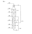
図5では、補助塔40により処理される低圧蒸気の供給源は、粗液体酸素を減圧してフラッシュ蒸気を含む粗液体酸素の流れ120を生成するときに生成されるフラッシュ蒸気である。粗液体酸素を過冷却しない場合に生成される粗液体酸素フラッシュ蒸気の量は粗液体酸素流量の15モル%ほどになることができる。このフラッシュ蒸気は補助塔40の外部で分離することができるが、分離していない粗液体酸素流120を図5に示したように塔40の塔底部へ送りそして液溜まりを分離器として使用するのが好適である。図5では、補助塔40は低圧塔30と異なる圧力で運転することができ、このときの窒素に富む塔頂蒸気の流れ152は、図示のように流れ130と混合されるよりも別の製品流として抜き出すことができる。
【0052】
図6では、補助塔40のための蒸気の供給源は空気膨張タービンからの吐出流106の全て又は一部である。図5におけるように、図6の装置の補助塔40は、低圧塔30とは異なる圧力で運転することができ、また流れ152は図示のように流れ130と混合されるよりも別の製品流として回収することができる。
【0053】
【実施例】
図1に示したのと同様の空気分離プラントを純粋酸素製品を製造するように設計した。粗液体酸素流120は過冷却しなかった。この二塔式の塔を、全部の部分で標準的密度のストラクチャードパッキングを使って設計した。低圧塔の部分IIIの必要断面積は、各部分におけるフラッディングを同一にするのに部分Iのそれより約20%大きくしなければならないことが分かった。
【0054】
同じ空気分離プラントを図5に従って設計する場合には、粗液体酸素流120中のフラッシュガスが補助蒸留塔40を上方に進む。この補助塔40から出てゆく廃棄ガス152の流量は全廃棄ガス流量の約10%であり、従って低圧塔30の部分IIIは全廃棄ガス流量の約90%を通過させる必要があるに過ぎない。補助塔40と低圧塔30からそれぞれ流れ152及び130として出てゆく廃棄ガスの純度は、おおよそ同じである。全廃棄窒素ガスの10%が補助塔40からの流れ152として製造されるとは言え、全還流の10%よりもわずかに多く(実際のところは10.6%)は補助塔40へ送られ、すなわち補助塔は一般に低圧塔の部分IIIにおけるよりもわずかに高い液対蒸気比で運転する。
【0055】
部分Iの断面積に変更はない。しかし、部分IIIについては、フラッディングに対して同じアプローチを取る場合、図1に従って設計したプラントについてよりも約10%小さくなる。補助塔の断面積は、部分IIIについてのそれのわずか約11%に過ぎず、且つ約10の理論段を必要とするに過ぎない。二つの設計についての最小エネルギー消費量の違いは、図5の設計では動力消費量が図1の設計を使用する場合のそれより0.1%以上大きくならないものであることが分かった。
【0056】
この明細書を通して、ある機能を実施するための手段という文脈での「手段」なる用語は、その機能を実施するために適合した及び/又は製作された少なくとも一つの装置・機構類を指すものである。
【0057】
本発明は好ましい態様を参照して先に説明した細目に限定されず、特許請求の範囲により明確にされる本発明の精神と範囲から逸脱することなしに多数の改変や変更を行うことができる、ということが認められよう。
【図面の簡単な説明】
【図1】典型的な二塔式低温空気蒸留装置を説明する図である。
【図2】補助塔のための酸素含有ガスを低圧塔の中間箇所から取る図1の典型的装置を基にした本発明の態様を説明する図である。
【図3】低圧塔に「トップハット」部分のある典型的な二塔式低温空気蒸留装置を説明する図である。
【図4】図2に示した本発明の態様を図3に示したタイプの塔装置用にどのように改造することができるかという一例を説明する図である。
【図5】補助塔のための酸素含有ガスを高圧塔の塔底から取り出される粗液体酸素から作られるフラッシュ蒸気により供給する本発明の態様を説明する図である。
【図6】補助塔のための酸素含有ガスを空気の膨張タービンにより供給する本発明の態様を説明する図である。
【符号の説明】
10…高圧塔
20…リボイラー/コンデンサー
30…低圧塔
40…補助分離塔[0001]
BACKGROUND OF THE INVENTION
The present invention relates to the field of cryogenic air distillation using an air separation unit (ASU) comprising two or more cryogenic distillation columns. The present invention is particularly applicable to an air separation device having a thermally coupled two-column distillation apparatus including a high pressure (HP) column and a low pressure (LP) column.
[0002]
[Prior art]
The distillation column of the air separation device has a plurality of column parts (sections). The hydrodynamic loads of the various tower parts vary considerably, especially when using structured packing as a mass transfer element in the towers. Or it is common to use three or more different diameters.
[0003]
The upper part of the low-pressure column of a two-column system is usually the point where the vapor flow rate of the column system is maximized, so it usually determines the maximum diameter used in the column system. Normally, the upper part of the low-pressure column is a bottleneck for the capacity evaluation of the column apparatus for the maximum specified tower diameter of the two-column apparatus. The high pressure column, and the lower part of the low pressure column, allow greater plant capacity if their diameter increases towards a fixed maximum diameter value. If the capacity of the two-column apparatus can be increased without increasing the diameter of the largest part of the two-column apparatus, the planar occupation area of the piping associated with the tower apparatus will not change significantly.
[0004]
The advantage of reducing the flow bottleneck in the upper part of the low pressure column is that the capacity of the double column system can be increased (under certain defined maximum column diameter constraints). In addition, the capacity of very large towers to be shipped is often determined by the diameter of the largest tower section. If the above flow bottlenecks can be mitigated, the maximum capacity of a single train twin tower could be increased.
[0005]
U.S. Pat. No. 5,100,388 (issued March 31, 1992) discloses a tower apparatus using structured packing, in which low density (high capacity) is achieved in the high hydrodynamic load portion of the tower. Structured packing is used, and high density (low volume) packing is used in the low hydrodynamic load section. Although this will achieve the goal described above, the low density packing has a much lower mass transfer performance than the high density packing.
[0006]
US Pat. No. 6,128,921 (issued October 10, 2000) discloses the arrangement of a plurality of low pressure columns, each providing a portion of the product, to increase the capacity of the plant. It does not address the problem that only the upper part of the low pressure column is responsible for the initial capacity bottleneck for the dual tower system.
[0007]
US Pat. No. 6,227,005 (issued May 8, 2001), International Publication No. 84/04957 (published December 20, 1984) and Richard Mason entitled “Intermediate Pressure Column in Air Separation”. Each of the publications of Research Disclosure by Publications (No. 425, September 1999, pp1185-1186, XP-000889172) has at least three distillation columns, each column operating at a different pressure. Disclosed is a process for producing oxygen and nitrogen using a distillation column apparatus, each intermediate pressure column having at least one reboiler / condenser.
[0008]
The purpose of the intermediate pressure column in both US Pat. No. 6,227,005 and WO 84/04957 is to provide a bottoms liquid that is further enriched with a feed stream containing liquid oxygen and a top gas that is low in oxygen. To pre-separate.
[0009]
[Patent Document 1]
US Pat. No. 5,100,388
[Patent Document 2]
US Pat. No. 6,128,921
[Patent Document 3]
US Pat. No. 6,227,005
[Patent Document 4]
International Publication No. 84/04957 Pamphlet
[Non-Patent Document 1]
“Intermediate Pressure Column in Air Separation”, Research Disclosure by Richard Mason Publications, No. 425, September 1999, pp1185-1186, XP-000889172
[0010]
[Problems to be solved by the invention]
It is an object of the present invention to provide an air separation apparatus that includes a multi-column distillation apparatus with increased capacity within the defined maximum column section diameter constraints.
[0011]
[Means for Solving the Problems]
The inventors do this by sending a small portion of the vapor stream that would normally pass through the upper portion of the low pressure column through an auxiliary separation column that receives reflux of the liquid stream from the high pressure column or from the high pressure column. I found what I could achieve. Typically, the steam flow in this auxiliary column is less than about 25%, preferably less than about 20%, and most preferably less than about 15% of the steam flow in the upper portion of the low pressure column. The column bottom liquid from the auxiliary column is returned to the low pressure column at an intermediate position above the column bottom.
[0012]
Using a multi-column distillation apparatus including at least a high-pressure column and a low-pressure column, air is separated at low temperature. The method feeds cooled feed air to a high pressure column to separate high pressure nitrogen enriched top vapor and crude liquid oxygen (CLOX), and at least one low pressure column feed stream comprising nitrogen and oxygen. Feeding to the low pressure column and separating it into low pressure nitrogen rich overhead vapor and liquid oxygen (LOX), and feeding the low pressure column with a liquid stream from or obtained from the high pressure column as reflux. An oxygen-containing gas containing about 50 mol% or less of oxygen is supplied to the auxiliary separation column, and separated into nitrogen-rich auxiliary column top vapor and oxygen-rich liquid. The oxygen rich liquid from the auxiliary column is fed to an intermediate location in the low pressure column, and the auxiliary column is fed with a liquid stream from or obtained from the high pressure column as reflux.
[0013]
In a preferred embodiment, the purpose of the auxiliary column is to eliminate the load on the upper part of the low pressure column by supplying it with a gas stream that otherwise had to pass through the upper part of the low pressure column. .
[0014]
The above apparatus is a high pressure column for separating cooled feed air into high pressure nitrogen-enriched overhead vapor and crude liquid oxygen, at least one low pressure column feed stream comprising nitrogen and oxygen is enriched in low pressure nitrogen. Low pressure column for separating the top vapor and liquid oxygen, pipe means for supplying the liquid stream from the high pressure column or obtained from the high pressure column to the low pressure column as reflux, oxygen containing about 50 mol% or less of oxygen An auxiliary separation tower for separating the contained gas into a nitrogen-rich auxiliary tower top vapor and an oxygen-rich liquid, a pipe means for supplying the oxygen-rich liquid from the auxiliary tower to an intermediate point of the low-pressure tower, And a conduit means for supplying a liquid stream from or obtained from the high pressure column to the auxiliary column as reflux.
[0015]
DETAILED DESCRIPTION OF THE INVENTION
According to a first aspect of the present invention, there is provided a method for the low temperature separation of air using a multi-column distillation apparatus comprising at least a high pressure (HP) column and a low pressure (LP) column,
Supplying cooled raw material air to a high-pressure column to separate high-pressure nitrogen-enriched top vapor and crude liquid oxygen;
Feeding at least one low pressure column feed stream comprising nitrogen and oxygen to the low pressure column to separate low pressure nitrogen rich overhead vapor and liquid oxygen;
Supplying the low pressure column with reflux of the liquid stream from the high pressure column or obtained from the high pressure column, supplying an oxygen-containing gas containing about 50 mol% or less of oxygen to the auxiliary separation column, and a nitrogen-rich auxiliary column top vapor Separating into oxygen-rich liquid,
Supplying oxygen-enriched liquid from the auxiliary column to an intermediate location in the low pressure column; and
Supplying the auxiliary column with reflux of the liquid obtained from the high-pressure column or obtained from the high-pressure column,
A method for cryogenic separation of air is provided.
[0016]
In a preferred embodiment, the oxygen-containing gas is effectively “washed” with a nitrogen-enriched liquid to prevent loss of oxygen molecules with the overhead vapor.
[0017]
Preferably, the steam flow in the auxiliary separation column is determined such that the diameter of the upper portion of the low pressure column is not greater than that for any other portion of the multi-column distillation column apparatus. Typically, the steam flow in the auxiliary column is less than about 25%, preferably less than about 20%, and most preferably less than about 15% of the steam flow in the upper portion of the low pressure column.
[0018]
The oxygen-containing gas can include about 50 to about 10 mole percent oxygen.
[0019]
In one preferred embodiment, the oxygen-containing gas comprises gas taken from an intermediate location in the low pressure column. Preferably, this gas is withdrawn from a location below the upper portion of the low pressure column where the vapor volume flow in the low pressure column is greatest.
[0020]
In another preferred embodiment, the oxygen-containing gas comprises flash vapor made from lowering the pressure of at least a portion of the crude liquid oxygen produced in the high pressure column. The amount of crude liquid oxygen flash vapor produced when the crude liquid oxygen is not supercooled can be as much as 15 mole percent of the crude liquid oxygen flow rate. The flash vapor can be separated from the crude liquid oxygen remaining after depressurization outside the column apparatus before being fed to the auxiliary separation column. Nevertheless, it is preferred to feed the crude liquid oxygen stream to the auxiliary separation column, ideally to the bottom of this column, where it is separated in the column pool.
[0021]
In yet another preferred embodiment, the oxygen-containing gas constitutes a portion of the feed air to the distillation apparatus. In such embodiments, the oxygen-containing gas preferably constitutes at least a portion of the discharge stream from the air expansion turbine. A portion of this turbine discharge stream may be supplied to the low pressure column.
[0022]
You may supply the oxygen-containing gas from two or more of these supply sources simultaneously to an auxiliary tower. For example, crude liquid oxygen flash vapor supplemented with deficiency by an oxygen-containing gas taken from an intermediate point of the low-pressure column and / or discharged from an air expansion turbine may be supplied to the auxiliary column.
[0023]
Usually, the operating pressure of the auxiliary separation column is the same as the operating pressure of the low pressure column. Such pressure relationship is such that gaseous nitrogen (GAN) extracted from the top of the low-pressure column is combined with nitrogen-rich auxiliary column top vapor extracted from the auxiliary column together with no pressure adjustment, and combined nitrogen. Enable to make product flow. However, the operating pressure of the auxiliary separation column may be different from the operating pressure of the low pressure column. Therefore, pressure regulation may be necessary for any stream moving between the low pressure column and the auxiliary separation column.
[0024]
Preferably, the process removes the nitrogen-enriched top vapor from the top of the high pressure column, condenses at least a portion thereof with a reboiler / condenser located at the bottom of the low pressure column, and removes the condensed nitrogen. It further includes supplying at least a portion of the reflux to the high pressure column. Condensed nitrogen produced by this reboiler / condenser or fluid taken from an intermediate location in the high pressure column may be fed to the low pressure column and auxiliary column as reflux. The reflux source for the low pressure column is not necessarily the same as that for the auxiliary column. The auxiliary column reflux is usually supplied by condensed nitrogen produced in a reboiler / condenser.
[0025]
Optionally, liquid air can be fed to the high pressure column for a given process cycle. In addition, a part of the high-pressure nitrogen-enriched top vapor may be taken out as a high-pressure gaseous nitrogen product. In addition, a portion of the nitrogen condensed in the reboiler / condenser can be removed as a liquid nitrogen (LIN) product.
[0026]
The crude liquid oxygen may be subjected to heat transfer or distillation before being supplied to the low pressure column. Some processes may require liquid air feed and / or air expander exhaust feed to the low pressure column.
[0027]
The liquid feed stream to the tower may be supercooled.
[0028]
According to a second aspect of the present invention, there is an apparatus for cryogenic separation of air by the method according to the first aspect,
A high-pressure column for separating the cooled feed air into high-pressure nitrogen-enriched top vapor and crude liquid oxygen,
A low pressure column for separating at least one low pressure column feed stream comprising nitrogen and oxygen into low pressure nitrogen rich overhead vapor and liquid oxygen;
Conduit means for supplying the liquid stream from or obtained from the high pressure column to the low pressure column as reflux,
A device comprising:
An auxiliary separation column for separating an oxygen-containing gas containing about 50 mol% or less of oxygen into a nitrogen-rich auxiliary column top vapor and an oxygen-rich liquid;
Conduit means for supplying oxygen rich liquid from the auxiliary column to an intermediate location in the low pressure column; and
Conduit means for supplying a liquid stream from or obtained from the high pressure column to the auxiliary column as reflux,
An air cryogenic separator is further provided.
[0029]
The low pressure column has several distillation sections (sections). Preferably, the diameter of the upper portion of the low pressure column is not greater than that for any other portion of the multi-column distillation column apparatus. Typically, the size of the auxiliary separation column is such that the auxiliary column can accept a steam flow of less than about 25%, preferably less than about 20%, and most preferably less than about 15% of the steam flow in the upper portion of the low pressure column. It is a thing.
[0030]
In one preferred embodiment of the second aspect of the present invention, the apparatus further comprises line means for supplying oxygen-containing gas from an intermediate location in the low pressure column to the auxiliary separation column. The middle point should be below the upper part of the low pressure column where the vapor volume flow in the low pressure column is the highest.
[0031]
In another preferred embodiment, the apparatus further comprises a decompression means for making flash vapor from crude liquid oxygen taken from the high pressure column, and a conduit means for supplying the flash vapor to the auxiliary separation column.
[0032]
In yet another preferred embodiment, the apparatus further includes conduit means for supplying a portion of the feed air to the distillation apparatus to the auxiliary tower. In such an embodiment, the apparatus preferably further includes an air expansion turbine and conduit means for supplying at least a portion of the exhaust stream from the turbine to the auxiliary separation tower.
[0033]
The apparatus can include any combination of features of these preferred embodiments so that oxygen-containing gases from more than one of these sources can be fed to the auxiliary column at any time.
[0034]
In general, the device further comprises
A reboiler / condenser for condensing at least a portion of the high-pressure nitrogen-enriched top vapor by indirect heat exchange with liquid oxygen at the bottom of the low-pressure column,
Line means for supplying high pressure nitrogen enriched vapor from the top of the high pressure column to the reboiler / condenser; and
Conduit means for supplying at least a portion of the condensed nitrogen from the reboiler / condenser as reflux to the top of the high pressure column;
including. The apparatus can include conduit means for supplying condensed nitrogen as reflux to the low pressure column, the auxiliary separation column, or both. The apparatus may include conduit means for supplying fluid drawn from an intermediate location in the high pressure column as reflux to the low pressure column, the auxiliary separation column, or both of these columns. This apparatus usually comprises line means for supplying condensed nitrogen as reflux to the auxiliary separation column.
[0035]
The auxiliary tower may be spatially located anywhere in the context of a multi-column distillation apparatus. For convenience, the auxiliary column is preferably raised so that an oxygen rich liquid at the bottom of the column can be fed to the low pressure column by the action of gravity, but it can be arranged side by side with the low pressure column, or It can also be placed below the low pressure column and the oxygen rich bottom liquid can be pumped to the low pressure column. In most multi-column cryogenic distillation units, the auxiliary column will be located directly above the low pressure column.
[0036]
In an apparatus involving the use of a “tophat” portion at the top of the low pressure column, the top hat portion and the auxiliary column can be integrated to form a split column. In such an embodiment, any geometry may be used to divide the cross section of the two towers. For example, in an embodiment in which the auxiliary tower is arranged side by side with the top hat portion, the auxiliary tower may surround the top hat portion in an annular shape, or vice versa. Alternatively, these towers may be divided areas or segments (segments) of a common circular outer shell, or may even be square towers within one tower. Any suitable shape and arrangement of dividing towers may be used.
[0037]
The steam flow in the auxiliary tower is usually less than 25% of the steam flow in the upper part of the low pressure tower. The addition of the auxiliary column essentially addresses the situation where only the upper part of the low pressure column determines the maximum cross-sectional diameter of the two column tower. By utilizing the present invention, the maximum tower diameter can be reduced, or the capacity of a two-column apparatus can be increased. In addition, standard high density packing with excellent mass transfer properties can be used in all parts of the column (this is in contrast to the teaching of US Pat. No. 5,100,388).
[0038]
The auxiliary column is relatively inexpensive because its diameter is usually smaller than that of the low pressure column and does not require many theoretical plates for mass transfer. Moreover, it does not require any additional reboiler or condenser as it modifies the prior art cycle in the manner of the present invention.
[0039]
Rather than using a multi-column low pressure column to increase plant capacity (eg, as in US Pat. No. 6,128,921), the steam flow is typically less than 25% of that in the upper portion of the low pressure column. By adding an auxiliary column that is, the capacity of a typical two-column distillation apparatus can be significantly increased. In addition, the auxiliary column generally has less than 15 theoretical separation stages, preferably about 10, and this increases the capacity of the multi-column tower with minimal impact on the size of the cold enclosure. Makes it possible to place
[0040]
Referring to FIG. 1, cooled
[0041]
A crude
[0042]
In the
[0043]
It should be noted in FIG. 1 that the volumetric flow rate of the vapors in the two parts II, III above the
[0044]
In the remaining figures, the same reference numerals are used to refer to parts of the apparatus corresponding to those shown in FIG.
[0045]
In FIG. 2, the oxygen concentration is about 50 mol% O. 2 Less than about 10 mol% O 2 The
[0046]
The
[0047]
In FIG. 2, the
[0048]
FIG. 3 shows a prior art dual tower apparatus. The apparatus of this figure differs from that of FIG. 1 in that there is an additional “top hat” portion IV in the
[0049]
FIG. 4 shows one possible arrangement where the apparatus shown in FIG. 3 is modified to include an
[0050]
2 and 4, the steam to be treated by the
[0051]
In FIG. 5, the source of low pressure steam that is processed by the
[0052]
In FIG. 6, the source of steam for the
[0053]
【Example】
An air separation plant similar to that shown in FIG. 1 was designed to produce a pure oxygen product. The crude
[0054]
If the same air separation plant is designed according to FIG. 5, the flash gas in the crude
[0055]
There is no change in the cross-sectional area of the portion I. However, for part III, taking the same approach to flooding is about 10% smaller than for the plant designed according to FIG. The cross section of the auxiliary tower is only about 11% of that for part III and only requires about 10 theoretical plates. The difference in the minimum energy consumption between the two designs was found to be such that the power consumption in the design of FIG. 5 was no greater than 0.1% over that of using the design of FIG.
[0056]
Throughout this specification, the term “means” in the context of means for performing a function refers to at least one device / mechanism adapted and / or fabricated to perform that function. is there.
[0057]
The present invention is not limited to the details described above with reference to preferred embodiments, and numerous modifications and changes can be made without departing from the spirit and scope of the invention as defined by the claims. It will be appreciated that.
[Brief description of the drawings]
FIG. 1 is a diagram illustrating a typical two-column cryogenic air distillation apparatus.
2 illustrates an embodiment of the present invention based on the exemplary apparatus of FIG. 1 that takes oxygen-containing gas for the auxiliary column from an intermediate location in the low pressure column.
FIG. 3 illustrates a typical two-column cryogenic air distillation apparatus with a “top hat” portion in the low pressure column.
4 is a diagram illustrating an example of how the embodiment of the invention shown in FIG. 2 can be modified for a tower apparatus of the type shown in FIG.
FIG. 5 illustrates an embodiment of the invention in which oxygen-containing gas for the auxiliary column is supplied by flash vapor made from crude liquid oxygen taken from the bottom of the high pressure column.
FIG. 6 illustrates an embodiment of the invention in which oxygen-containing gas for the auxiliary tower is supplied by an air expansion turbine.
[Explanation of symbols]
10 ... High pressure tower
20 ... Reboiler / Condenser
30 ... Low pressure tower
40 ... auxiliary separation tower
Claims (9)
冷却した原料空気(100)を高圧塔(10)へ供給して高圧の窒素富化塔頂蒸気と粗液体酸素とに分離すること、
窒素と酸素を含む少なくとも一つの低圧塔原料流(104、106、120)を低圧塔(30)へ供給して低圧の窒素に富む塔頂蒸気と液体酸素とに分離すること、
高圧塔(10)からの又は高圧塔(10)から得られる液体流(110)を還流として低圧塔(30)へ供給すること、
50モル%以下の酸素を含む酸素含有ガス(106、120、150)を補助分離塔(40)へ供給して、窒素に富む補助分離塔塔頂蒸気と酸素に富む液とに分離し、当該補助分離塔にはリボイラーがなく、そして当該酸素含有ガスは低圧塔(30)の中間の箇所から取り出されたガス(150)を含むこと、
補助分離塔(40)からの酸素に富む液(154)を低圧塔(30)の中間の箇所へ供給すること、及び
高圧塔(10)からの又は高圧塔(10)から得られる液体流(112)を還流として補助分離塔(40)へ供給すること、
を含む空気の低温分離方法。A method for the low temperature separation of air using a multi-column distillation apparatus comprising at least a high pressure column (10) and one low pressure column (30),
Supplying cooled raw air (100) to the high pressure column (10) to separate the high pressure nitrogen-enriched top vapor and crude liquid oxygen;
Supplying at least one low pressure column feed stream (104, 106, 120) comprising nitrogen and oxygen to the low pressure column (30) to separate low pressure nitrogen rich overhead vapor and liquid oxygen;
Feeding a liquid stream (110) from or obtained from the high pressure column (10) as reflux to the low pressure column (30);
5 0 mole percent of an oxygen-containing gas containing oxygen (106,120,150) supplied to the auxiliary separation column (40), and separated into a liquid rich in the auxiliary separation column overhead vapor and oxygen-rich nitrogen, The auxiliary separation column has no reboiler, and the oxygen-containing gas comprises a gas (150) taken from an intermediate point of the low pressure column (30);
Supplying oxygen-enriched liquid (154) from the auxiliary separation column (40) to an intermediate location in the low pressure column (30), and a liquid stream from or obtained from the high pressure column (10) ( 112) as reflux to the auxiliary separation column (40),
A method for the low temperature separation of air.
そのうちの少なくとも一部分を低圧塔(30)の塔底部に位置するリボイラー/コンデンサー(20)で凝縮させること、及び
凝縮した窒素のうちの少なくとも一部分を補助分離塔(40)へ還流として供給すること、
を更に含む、請求項1から5までのいずれか一つに記載の方法。Removing high-pressure nitrogen-enriched top vapor from the top of the high-pressure column (10);
Condensing at least a portion of it in a reboiler / condenser (20) located at the bottom of the low pressure column (30), and supplying at least a portion of the condensed nitrogen to the auxiliary separation column (40) as reflux,
The method according to any one of claims 1 to 5, further comprising:
冷却した原料空気(100)を高圧の窒素富化塔頂蒸気と粗液体酸素とに分離するための高圧塔(10)、
窒素と酸素とを含む少なくとも一つの低圧塔原料流(104、106、120)を低圧の窒素に富む塔頂蒸気と液体酸素とに分離するための低圧塔(30)、
高圧塔(10)からの又は高圧塔(10)から得られる液体流を還流として低圧塔(30)へ供給するための管路手段(110)、
50モル%以下の酸素を含む酸素含有ガス(106、120、150)を分離して窒素に富む補助分離塔塔頂蒸気と酸素に富む液とにするための補助分離塔であって、リボイラーを持たない補助分離塔(40)、
低圧塔の中間の箇所から補助分離塔へ酸素含有ガスを供給するための導管手段、
補助分離塔(40)からの酸素に富む液を低圧塔(30)の中間の箇所へ供給するための管路手段(154)、及び
高圧塔(10)からの又は高圧塔(10)から得られる液体流を還流として補助分離塔(40)へ供給するための管路手段(112)、
を含む空気の低温分離装置。An apparatus for cryogenic separation of air by the method of claim 1, comprising:
A high pressure column (10) for separating the cooled feed air (100) into high pressure nitrogen-enriched top vapor and crude liquid oxygen;
A low pressure column (30) for separating at least one low pressure column feed stream (104, 106, 120) comprising nitrogen and oxygen into low pressure nitrogen rich overhead vapor and liquid oxygen;
Conduit means (110) for supplying a liquid stream from or obtained from the high pressure column (10) as reflux to the low pressure column (30);
An auxiliary separation column for separating an oxygen-containing gas (106, 120, 150) containing 50 mol% or less of oxygen into a nitrogen-rich auxiliary separation tower top vapor and an oxygen-rich liquid, Auxiliary separation tower (40) without
Conduit means for supplying oxygen-containing gas from the middle of the low pressure column to the auxiliary separation column;
A line means (154) for supplying the oxygen rich liquid from the auxiliary separation column (40) to the middle of the low pressure column (30), and from the high pressure column (10) or from the high pressure column (10) Line means (112) for supplying the resulting liquid stream as reflux to the auxiliary separation column (40),
Including air cryogenic separator.
Applications Claiming Priority (2)
| Application Number | Priority Date | Filing Date | Title |
|---|---|---|---|
| EP01310153.0 | 2001-12-04 | ||
| EP01310153A EP1318367B2 (en) | 2001-12-04 | 2001-12-04 | Process and apparatus for the cryogenic separation of air |
Publications (3)
| Publication Number | Publication Date |
|---|---|
| JP2003185337A JP2003185337A (en) | 2003-07-03 |
| JP2003185337A5 JP2003185337A5 (en) | 2008-01-10 |
| JP4490033B2 true JP4490033B2 (en) | 2010-06-23 |
Family
ID=8182513
Family Applications (1)
| Application Number | Title | Priority Date | Filing Date |
|---|---|---|---|
| JP2002352661A Expired - Fee Related JP4490033B2 (en) | 2001-12-04 | 2002-12-04 | Low temperature separation method and apparatus for air |
Country Status (6)
| Country | Link |
|---|---|
| US (1) | US6651460B2 (en) |
| EP (1) | EP1318367B2 (en) |
| JP (1) | JP4490033B2 (en) |
| AT (1) | ATE356326T1 (en) |
| DE (1) | DE60127145T3 (en) |
| ES (1) | ES2278703T5 (en) |
Families Citing this family (9)
| Publication number | Priority date | Publication date | Assignee | Title |
|---|---|---|---|---|
| US8640496B2 (en) * | 2008-08-21 | 2014-02-04 | Praxair Technology, Inc. | Method and apparatus for separating air |
| US8448463B2 (en) * | 2009-03-26 | 2013-05-28 | Praxair Technology, Inc. | Cryogenic rectification method |
| FR2947621A1 (en) * | 2009-07-06 | 2011-01-07 | Air Liquide | Air separation apparatus for industrial site, has pipes connected to average pressure column and low pressure column, respectively, where each pipe emerges at interior of double column, and is adapted to be connected to other column |
| US8820115B2 (en) * | 2009-12-10 | 2014-09-02 | Praxair Technology, Inc. | Oxygen production method and apparatus |
| US20110138856A1 (en) * | 2009-12-10 | 2011-06-16 | Henry Edward Howard | Separation method and apparatus |
| US9103587B2 (en) * | 2009-12-17 | 2015-08-11 | L'Air Liquide Société Anonyme pour l'Etude et l'Exploitation des Procedes Georges Claude | Process and apparatus for the separation of air by cryogenic distillation |
| JP2020521098A (en) | 2017-05-16 | 2020-07-16 | イーバート,テレンス,ジェイ. | Apparatus and process for liquefying gas |
| CN115885146A (en) * | 2020-07-22 | 2023-03-31 | 乔治洛德方法研究和开发液化空气有限公司 | Argon enhancement method and apparatus |
| US11439946B2 (en) | 2020-09-30 | 2022-09-13 | Air Products And Chemicals, Inc. | Mixed bead layering arrangement for thermal swing adsorption application |
Family Cites Families (14)
| Publication number | Priority date | Publication date | Assignee | Title |
|---|---|---|---|---|
| GB2057660B (en) * | 1979-05-17 | 1983-03-16 | Union Carbide Corp | Process and apparatus for producing low purity oxygen |
| US4604116A (en) † | 1982-09-13 | 1986-08-05 | Erickson Donald C | High pressure oxygen pumped LOX rectifier |
| US4605427A (en) * | 1983-03-31 | 1986-08-12 | Erickson Donald C | Cryogenic triple-pressure air separation with LP-to-MP latent-heat-exchange |
| FR2584803B1 (en) † | 1985-07-15 | 1991-10-18 | Air Liquide | AIR DISTILLATION PROCESS AND INSTALLATION |
| US5100448A (en) | 1990-07-20 | 1992-03-31 | Union Carbide Industrial Gases Technology Corporation | Variable density structured packing cryogenic distillation system |
| GB9213776D0 (en) * | 1992-06-29 | 1992-08-12 | Boc Group Plc | Air separation |
| FR2774753B1 (en) * | 1998-02-06 | 2000-04-28 | Air Liquide | AIR DISTILLATION SYSTEM COMPRISING MULTIPLE CRYOGENIC DISTILLATION UNITS OF THE SAME TYPE |
| FR2778234B1 (en) * | 1998-04-30 | 2000-06-02 | Air Liquide | AIR DISTILLATION SYSTEM AND CORRESPONDING COLD BOX |
| US6276170B1 (en) * | 1999-05-25 | 2001-08-21 | Air Liquide Process And Construction | Cryogenic distillation system for air separation |
| US6347534B1 (en) * | 1999-05-25 | 2002-02-19 | Air Liquide Process And Construction | Cryogenic distillation system for air separation |
| DE19933558C5 (en) † | 1999-07-16 | 2010-04-15 | Linde Ag | Three-column process and apparatus for the cryogenic separation of air |
| US6227005B1 (en) * | 2000-03-01 | 2001-05-08 | Air Products And Chemicals, Inc. | Process for the production of oxygen and nitrogen |
| FR2814229B1 (en) * | 2000-09-19 | 2002-10-25 | Air Liquide | METHOD AND PLANT FOR AIR SEPARATION BY CRYOGENIC DISTILLATION |
| US6397631B1 (en) † | 2001-06-12 | 2002-06-04 | Air Products And Chemicals, Inc. | Air separation process |
-
2001
- 2001-12-04 DE DE60127145T patent/DE60127145T3/en not_active Expired - Lifetime
- 2001-12-04 EP EP01310153A patent/EP1318367B2/en not_active Expired - Lifetime
- 2001-12-04 AT AT01310153T patent/ATE356326T1/en not_active IP Right Cessation
- 2001-12-04 ES ES01310153T patent/ES2278703T5/en not_active Expired - Lifetime
-
2002
- 2002-10-29 US US10/282,406 patent/US6651460B2/en not_active Expired - Fee Related
- 2002-12-04 JP JP2002352661A patent/JP4490033B2/en not_active Expired - Fee Related
Also Published As
| Publication number | Publication date |
|---|---|
| ATE356326T1 (en) | 2007-03-15 |
| DE60127145T2 (en) | 2007-12-13 |
| EP1318367B1 (en) | 2007-03-07 |
| US20030101745A1 (en) | 2003-06-05 |
| EP1318367A1 (en) | 2003-06-11 |
| US6651460B2 (en) | 2003-11-25 |
| ES2278703T5 (en) | 2010-03-17 |
| EP1318367B2 (en) | 2009-11-11 |
| DE60127145D1 (en) | 2007-04-19 |
| JP2003185337A (en) | 2003-07-03 |
| DE60127145T3 (en) | 2010-04-15 |
| ES2278703T3 (en) | 2007-08-16 |
Similar Documents
| Publication | Publication Date | Title |
|---|---|---|
| JP5425100B2 (en) | Cryogenic air separation method and apparatus | |
| CN108027201B (en) | method and apparatus for argon removal and argon recovery | |
| US10145609B2 (en) | Method ad apparatus for argon recovery in a cryogenic air separation unit integrated with a pressure swing adsorption | |
| US8448463B2 (en) | Cryogenic rectification method | |
| JP3169627B2 (en) | Air separation method | |
| CN107850387B (en) | Method and apparatus for argon recovery in a cryogenic air separation unit integrated with a pressure swing adsorption system | |
| JP2002327982A (en) | Three-tower type air-separation installation, argon- production method and system with crude argon tower | |
| JPH0731004B2 (en) | Air distillation method and plant | |
| JP2004028572A (en) | Air fractionation process and air fractionation installation provided with mixing column and krypton and/or xenon recovery device | |
| KR20110026435A (en) | Nitrogen liquefier retrofit for an air separation plant | |
| JPH07198249A (en) | Method and equipment for separating air | |
| JP4490033B2 (en) | Low temperature separation method and apparatus for air | |
| US20110138856A1 (en) | Separation method and apparatus | |
| US6141989A (en) | Air separation | |
| JP2007064617A (en) | Method of manufacturing krypton and/or xenon by cryogenic air separation | |
| EP2510295B1 (en) | Oxygen production method and apparatus for enhancing the process capacity | |
| KR20200098627A (en) | Systems and methods for flexible recovery of argon from cryogenic air separation units | |
| JP7451532B2 (en) | Apparatus and method for separating air by cryogenic distillation | |
| JPH11325717A (en) | Separation of air | |
| US11602713B2 (en) | Method for cryogenic separation of air, and air separation plant | |
| AU706679B2 (en) | Air separation | |
| AU2013339789A1 (en) | Process for the low-temperature separation of air in an air separation plant and air separation plant | |
| JPH1072612A (en) | Oxygen steelmaking method | |
| AU719240B2 (en) | Air separation | |
| US6170291B1 (en) | Separation of air |
Legal Events
| Date | Code | Title | Description |
|---|---|---|---|
| A621 | Written request for application examination |
Free format text: JAPANESE INTERMEDIATE CODE: A621 Effective date: 20051007 |
|
| A521 | Request for written amendment filed |
Free format text: JAPANESE INTERMEDIATE CODE: A523 Effective date: 20071115 |
|
| A977 | Report on retrieval |
Free format text: JAPANESE INTERMEDIATE CODE: A971007 Effective date: 20080529 |
|
| A131 | Notification of reasons for refusal |
Free format text: JAPANESE INTERMEDIATE CODE: A131 Effective date: 20080603 |
|
| A601 | Written request for extension of time |
Free format text: JAPANESE INTERMEDIATE CODE: A601 Effective date: 20080902 |
|
| A602 | Written permission of extension of time |
Free format text: JAPANESE INTERMEDIATE CODE: A602 Effective date: 20080905 |
|
| A131 | Notification of reasons for refusal |
Free format text: JAPANESE INTERMEDIATE CODE: A131 Effective date: 20100105 |
|
| A521 | Request for written amendment filed |
Free format text: JAPANESE INTERMEDIATE CODE: A523 Effective date: 20100201 |
|
| TRDD | Decision of grant or rejection written | ||
| A01 | Written decision to grant a patent or to grant a registration (utility model) |
Free format text: JAPANESE INTERMEDIATE CODE: A01 Effective date: 20100302 |
|
| A01 | Written decision to grant a patent or to grant a registration (utility model) |
Free format text: JAPANESE INTERMEDIATE CODE: A01 |
|
| A61 | First payment of annual fees (during grant procedure) |
Free format text: JAPANESE INTERMEDIATE CODE: A61 Effective date: 20100401 |
|
| FPAY | Renewal fee payment (event date is renewal date of database) |
Free format text: PAYMENT UNTIL: 20130409 Year of fee payment: 3 |
|
| R150 | Certificate of patent or registration of utility model |
Free format text: JAPANESE INTERMEDIATE CODE: R150 |
|
| LAPS | Cancellation because of no payment of annual fees |