JP4488672B2 - Massage machine - Google Patents
Massage machine Download PDFInfo
- Publication number
- JP4488672B2 JP4488672B2 JP2002275295A JP2002275295A JP4488672B2 JP 4488672 B2 JP4488672 B2 JP 4488672B2 JP 2002275295 A JP2002275295 A JP 2002275295A JP 2002275295 A JP2002275295 A JP 2002275295A JP 4488672 B2 JP4488672 B2 JP 4488672B2
- Authority
- JP
- Japan
- Prior art keywords
- drive unit
- treatment element
- massage
- user
- massage machine
- Prior art date
- Legal status (The legal status is an assumption and is not a legal conclusion. Google has not performed a legal analysis and makes no representation as to the accuracy of the status listed.)
- Expired - Fee Related
Links
Images


Description
【0001】
【発明の属する技術分野】
本発明は、マッサージ機に関するものである。
【0002】
【従来の技術】
例えば、特許文献1に記載されているように、使用者の肩や背中に対して揉み、叩き等のマッサージを行う施療子と、該施療子をマッサージ動作させるマッサージ機構とを、椅子型の施療台の背もたれ部に対して上下移動自在に備えている椅子型マッサージ機が従来より知られている。このマッサージ機では、施療子の使用者側への突出量を変更する機構と、施療子が使用者の背中等を押圧する力を検出する圧力センサーとをマッサージ機構に備えたものとなっており、圧力センサーによって揉み等の強さを検出するとともに、その検出信号にしたがって施療子の突出量を変更し、適度な強さでマッサージを行えるようにしたものであった。
【0003】
【特許文献1】
特開平6−190012号公報
【0004】
【発明が解決しようとする課題】
上記従来のマッサージ機においては、施療子を使用者側に突出する支持アームの先端に取り付け、この支持アームを前後左右又は上下等に複雑に揺動させることによって揉みや叩き等のマッサージ動作を可能としており、したがって、マッサージ機構は、支持アームに複雑な動きをさせるために多数の軸やカム、伝動装置等を有した複雑な構造となっている。そして、従来のマッサージ機は、この複雑な構造となるマッサージ機構に対して、施療子の突出量を変更する機構をも加えた構成となっていたために、より一層構造の複雑化を招き、マッサージ機構の組み立てや調整が困難になるとともに、コスト増を招来するものとなっていた。
【0005】
また、揉みや叩き、施療子の突出量調整を全て支持アームの揺動で行っているために、これら各動作における支持アームの揺動の組み合わせによって施療子の位置制御等が困難となるものであった。本発明は、このような実情に鑑みてなされたものであって、施療子をマッサージ動作させる駆動ユニット自体を使用者側へ出退可能とすることによって、使用者に対する施療子の突出量を変更可能としながらも駆動ユニットの構造を複雑化することのないマッサージ機を提供することを目的とする。
【0006】
【課題を解決するための手段】
本発明は、上記目的を達成するために以下の技術的手段を講じている。すなわち、本発明は、座部と背もたれ部とを有する椅子型マッサージ機において、前記背もたれ部の内部に、移動機枠が高さ方向へ移動可能に設けられ、前記移動機枠に、施療子をマッサージ動作させる駆動ユニットが、正逆回転可能な電動モータを有する出退駆動部により使用者側に出退移動自在に取り付けられ、前記駆動ユニットは、電動モータよりなる原動部と、該原動部により駆動される駆動アームと、該駆動アームに左右方向の支軸を介して軸芯回りに回動自在に枢結された支持アームと、を有して前記施療子に揉み動作又は叩き動作を行わせるよう構成され、前記施療子は、前記支持アームの上下両端部に設けられ、前記支持アームは、該支持アームの上部側が前方突出する方向への弾性が付与されており、前記駆動ユニットは、前記出退駆動部が有する電動モータの作動により前記移動機枠に対して使用者に対向する方向と略平行に出退移動自在で、任意の出退位置で保持可能であり、前記施療子の突出量を漸次変化させながら該施療子に揉み動作又は叩き動作を行わせることを特徴とするものである。
【0007】
これによれば、駆動ユニットを使用者側へ出退移動させることにより、使用者に対する施療子の突出量を変更でき、マッサージの強さ等を適度に調整するようなことが可能となる。そして、駆動ユニット自体を出退移動させることにより、駆動ユニット内の構造の複雑化を招くこともほとんどなく、組み立てや調整等も容易に行えるようになる。また、施療子の突出量を変更可能としているにも関わらず、マッサージ動作のための駆動ユニット内の構造を特に変更する必要がないため、従来からある部品を流用することが可能となってコストの低減も図られるようになる。出退動作機構は、前記駆動ユニットを、使用者に対向する方向と略平行に出退移動自在に備えた構成を採用しているので、簡単な構成で駆動ユニットの出退移動が可能になり、使用者に対する施療子の位置ズレが防止され、施療子の位置制御が容易になるとともに効果的なマッサージ動作が維持できるものとなる。
【0008】
また、前記施療子に付与される負荷を検出する検出器が設けられ、施療子の使用者側への突出量を、前記検出器からの検出値に基づいて制御するものである。また、前記駆動ユニットは、使用者に対向する方向と略平行に出退移動自在に案内支持するレールが設けられているものである。また、前記レールは、前記駆動ユニットに上下一対設けられているものである。また、前記駆動ユニットは、パンタグラフ型のリンク機構が設けられており、該リンク機構の伸縮によって、使用者に対向する方向と略平行に出退移動自在に支持されているものである。
【0009】
【発明の実施の形態】
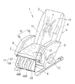
以下、本発明の実施の形態を図面を参照して説明する。図6及び図7は、本発明にかかるマッサージ機1を示しており、このマッサージ機1は、使用者が着座する座部2と、使用者の背中を支持する背もたれ部3とを有する椅子本体(施療台)4を具備した椅子型マッサージ機とされている。椅子本体4は、背もたれ部3、座部2の他に、フットレスト8を有しているとともに、座部2の両側に肘置き部9を一体に備えた脚体10を有しており、背もたれ部3及びフットレスト8は、リクライニングのための適宜電動駆動機構、流体圧駆動機構又は手動構造等により、座面部2に対する角度変更が可能となっている。
【0010】
前記座部2には、使用者の尻や太股の裏側をマッサージする第1マッサージ部16が備えられ、フットレスト8には、脹ら脛、足首等をマッサージする第2マッサージ部17が備えられ、背もたれ部3には、使用者の肩や背中、腰等をマッサージする第3マッサージ部(マッサージ機構)7が備えられている。第1マッサージ部16は、座部2の後寄りに設けられた左右2個のマッサージ具18と、前寄りに設けられた左右2個のマッサージ具19とを有しており、これら各マッサージ具18,19は、空気の供給・排出により膨張・収縮するエアセル18A、19Aと、該エアセル18A,19Aの上部に設けられた施療子18B、19Bとを有している。
【0011】
前記エアセル18A,19Aは、酢酸ビニル等の可撓性及び弾力性に優れた樹脂により外周面を蛇腹形状とした略円筒形に形成されており、座部2の下側に備えたエアコンプレッサー(エア供給源)45からの圧縮空気が電磁弁を介して供給されて上下方向に伸縮するようになっている。そして、このエアセル18A,19Bの伸縮によって後2つのマッサージ具18で尻をマッサージ可能とし、前2つのマッサージ具19で太股の裏側をマッサージ可能に構成している。
【0012】
第2マッサージ部17は、前記フットレスト8に設けられており、左右の足を別々に挟持することができる溝型の足保持部46と、左右各足保持部46の溝底壁46Aと左右両側壁46Bとにそれぞれ設けられたマッサージ具47,48とを有している。このマッサージ具47,48も、上記と同様にエアセル47A,48Aと該エアセル47A、48Aの先端部に設けられた施療子47B、48Bとを有し、エアセル47A、48Aには前記コンプレッサー45からの圧縮空気が電磁弁を介して供給され、各エアセル47A、48Aを膨張収縮することによって、溝底壁46Aのマッサージ具47で脹ら脛を、側壁46Bのマッサージ具48で足首をそれぞれマッサージ可能に構成している。
【0013】
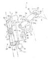
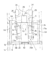
椅子本体4の背もたれ部3には、その内部で移動駆動部5により高さ方向へ移動可能に設けられた移動機枠6が設けられ、この移動機枠6に対して第3マッサージ部(マッサージ機構)7が設けられている。また、このマッサージ機構7の前面側は、布製、革製等の可撓性を有するカバー部材15によって覆われている。移動機枠6は、図1及び図2にも示すように、左右枠体6A、6Aの上下両端が上下枠体6B、6Bによって連結されてなる方形状を呈し、移動駆動部5は、背もたれ部3の高さ方向に沿って回転自在に設けられた縦送りネジ軸11と、この縦送りネジ軸11を正逆回転可能にする減速機付き電動機等よりなる原動部12とを有しており、縦送りネジ軸11は、移動機枠6に設けられた雌ネジ体6Cに上下貫通状に螺合されている。また、移動機枠6の左右両側部には、上下一対の走行ローラ13が設けられ、この走行ローラ13は、背もたれ部3内に高さ方向に設けられた2本の案内レール14に転動自在に取り付けられている。
【0014】
而して、マッサージ機構7は、移動駆動部5の作動により、座面部2に着座した使用者の上体背面に沿って首側又は腰側へ高さ方向に移動させられる。なお、前記マッサージ機構7の高さ方向の移動位置(移動量)は、図示しない上下位置検出手段によって検出されるようになっており、この上下位置検出手段としては、例えば、縦送りネジ軸11や原動部12の回転数や回転角度をロータリーエンコーダ等によってパルス化するとともに、そのパルス数をカウントする構成や、マッサージ機構7の高さ位置を光電センサ等によって光学的に検出する構成など、適宜手段が採用される。
【0015】
また、移動駆動部5としては、巻掛駆動機構やラックとピニオンの噛合構造、または流体圧シリンダ等を用いた昇降駆動構造等に置換可能である。マッサージ機構7は、使用者の身体をマッサージする施療子26と、該施療子26をマッサージ動作させる駆動ユニット20とを有している。駆動ユニット20は、ケース20Aと、該ケースの上部に設けられた電動モータよりなる原動部23と、ケース20A内に配置された伝動軸及びクラッチ(図示略)と、左右方向の揉み動作軸21及び叩き動作軸22とを有している。
【0016】
揉み動作軸21は、ケース20Aを左右に貫通するとともにその両端部がケース20Aの左右両側から突出されており、叩き動作軸22は、揉み動作軸21の下側に略平行に設けられ、ケース20Aを左右に貫通するとともにその両端部がケース20Aの左右両側から突出されている。そして、前記原動部23からの動力は、ケース20A内の伝動軸及びクラッチを介して揉み動作軸21及び叩き動作軸22に選択的に伝達されるようになっている。
【0017】
駆動ユニット20は、揉み動作軸21及び叩き動作軸22によって保持された左右方向(使用者の身体の幅方向)一対の駆動アーム24と、各駆動アーム24の先端部に連結された支持アーム25も有して構成され、該支持アーム25の上下両端部に、左右方向の支持軸30を介して回転自在にローラー状の施療子26が取り付けられている。揉み動作軸21の両端には、その回転軸心に対して偏心・偏角するように傾斜された傾斜軸部21aが設けられ、この傾斜軸部21aに対して、駆動アーム24の後端がベアリングを介して取り付けられるようになっている。
【0018】
支持アーム25は、側面視くの字状の板材により形成され、その上下中途部が駆動アーム24の先端に左右方向の支軸24aを介して軸心回りに回動自在に枢結され、該支軸24aより上部及び下部が使用者側に向けて前斜め上方及び前斜め下方に突出するようになっている。また、支軸24aの下側では、支持アーム25と駆動アーム24とに亘って引っ張りコイルバネ27が架設されており、支持アーム25の上部側が前方突出する方向への弾性が付与されている。
【0019】
叩き動作軸22の両端には、その回転軸心に対して互いに逆方向に偏心された偏心軸部22aが設けられており、この偏心軸部22aに、ベアリングを介して連結ロッド28の下端が揺動自在に連結され、連結ロッド28の上端が駆動アーム24の下面部に玉継手等を介して揺動自在に連結されている。上記構成により、原動部23が揉み動作軸21を回転駆動すると、揉み動作軸21両端の傾斜軸部21aによって、左右に対応する施療子26が相互近接・相互離反するような左右移動を含む円周運動をし、これによって揉み動作を行う。
【0020】
また、叩き動作軸22が回転駆動すると、その両端の偏心軸部22aによって、連結アーム28を介して駆動アーム24を上下に往復揺動し、この駆動アーム24に枢結された支持アーム25を介して施療子26が叩き動作を行うようになっている。そして、揉み動作軸21及び叩き動作軸22を停止した状態で移動機枠6を上下に移動すると、施療子26が背中や腰等をさすりマッサージ(ローリングマッサージ)するようになっている。
【0021】
なお、前記揉み動作軸21及び叩き動作軸22には、原動部23からの動力が駆動ユニット20内のクラッチを介して選択的に伝達されるようになっているが、各動作軸21,22に対して個別、専用の原動部を備えるようにしてもよい。左右支持アーム25の上部側に備えた各施療子26の両方又は片方に対して、当該施療子26に付与される負荷を検出する検出器40が備えられている。この施療子26の取付構造を示す図4及び図5において、前記支持アーム25には、左右方向の軸心を有する前記支持軸30が左右内方に突出して備えられ、前記施療子26は、その中央にボス体31を有しており、このボス体31が前記支持軸30に回動自在に套嵌されている。また、支持軸30の先端部には、施療子26の抜止をなす取付ナット32がワッシャ(押さえ部材)32aを介して螺合されている。
【0022】
ボス体31は、施療子26の中央に形成した貫通孔の内周に嵌合される筒部31aと、この筒部31aの左右両側で施療子26を挟み込む鍔部31bとを有しており、筒部31aは軸心方向中央部で左右に2分割された形体とされている。また、前記施療子26の外周面は、左右内方側に向けて径方向内方に移行するような円弧状の傾斜面26aに形成されている。前記検出器40としては、例えば、図5(b)に示すように、絶縁体としてのゴム等の弾性材料に対して導電性粒子を配合した感圧導電性エラストマー40aを、一対の電極40b間に貼り付けることによって構成された圧力(感圧)センサーが用いられている。そして、この圧力センサー40は、支持アーム25とボス体31との間で支持軸30に套嵌するようにドーナツ円盤型に形成され、その左右外側面が支持アーム25の左右内側面に接触するようになっている。
【0023】
圧力センサー40の左右内側面は、ドーナツ円盤型の覆板36によって覆われており、この覆板36の左右内側面がボス体31に接触している。覆板36の外側面には複数の回り止め突部42が突出され、支持アーム25に形成した挿通孔43に支持軸30の軸心方向に移動自在に挿通されている。これによって、覆板36は支持軸30回りの回動が規制された状態で圧力センサー40を左右外側へと押圧できるようになっている。なお、覆板36は、圧力センサー40を押圧する押圧部材としての機能だけでなく、回転する施療子26と圧力センサー40との直接的な接触を防止して圧力センサー40の摩耗等を防止する保護部材としての機能を有している。
【0024】
前記ボス体31とワッシャ32aとの間には、両者の間隔を保持するためのスペーサ部材35,41が支持軸30に套嵌して備えられている。このスペーサ部材35,41は、ポリエチレン等の合成樹脂材によりドーナツ円盤型に形成された第1部材35と、ポリエチレンゴム、スポンジゴム等の弾性材料にて形成された第2部材41とを有し、第1部材35の左右内側面がボス体31に接触するようになっている。第2部材41は、支持軸30に対して取付ナット32を締め付けることによって軸心方向に圧縮されるとともに、その弾性復元力によって第1部材35、ボス体31及び覆板36を介して圧力センサー40を押圧するようになっており、従って、圧力センサー40には、施療子26が左右方向の外力を受けていない状態でも予め圧力が付与されるようになっている。
【0025】
なお、第1部材35及び覆板36は、摩擦抵抗の小さい材質によって形成するか、少なくともボス体31への接触面に低摩擦処理を施した構成とするのが好ましく、このようにすれば、施療子26の支持軸30回りの回転を円滑に行えるようになる。上記構成により、施療子26に揉み動作を行わせると、その左右方向の移動に対する使用者側からの反力で、施療子26には左右方向の負荷が付与される。この際施療子26は、覆板36を介して圧力センサー40を押圧することから、その圧力が圧力センサー40によって検出される。
【0026】
このように検出された圧力は、その大小が揉みの強さに比例するものとなるため、この検出値をマッサージ機1の制御部にフィードバックすることによって、適切な揉み制御(例えば、後述するように使用者に対する施療子26の突出量を変更するような制御)を行うことが可能となり、より効果的な揉み動作を行い得るものとなる。圧力センサー40には、予かじめ圧力が付与された状態となっていることから、例えば、施療子26と支持アーム25との軸心方向間のガタや遊びに起因して施療子26が受ける負荷の検出精度を損なうようなこともなく、正確な圧力検出が行えるようになる。
【0027】
圧力センサー40は、支持軸30回りに回転する施療子26側ではなく、支持アーム25側(実質的には支持軸30)に設けられ、しかも覆板36が支持軸30回りの回動を規制されているため、圧力センサー40も施療子26の回転によって回動することなく位置規制されるようになり、これによって、圧力センサー40の配線が容易に行える。上記圧力センサー40は、使用者の体格に応じたマッサージ動作を行うべく、使用者の肩S等の高さ位置を判別するために利用することができるようになっている。
【0028】
すなわち、マッサージ動作、例えば、揉みや叩き等の一連の動作をプログラムした自動マッサージを開始するに当たり、施療子26を使用者の頭部側から下方に移動することによって、支持アーム25上側の施療子26を肩Sに当接すると、肩Sに作用する押圧力の反力として施療子26に対して負荷Fが付与される。そして、この負荷Fは主に上下方向成分を有するものとなるが、施療子26はその左右外側で片持ち状に支持されていることから、矢示Mで示すようなモーメントが発生し、更にこのモーメントMによって、支持軸30とボス体31との隙間等を介して施療子26の上部側を左右外側に傾けるような力が起生される。
【0029】
また、前記負荷Fは、施療子26外周の傾斜面26aや支持軸30に付与される若干の傾斜、施療子26自体の弾性変形等の要因によって、実質的には2点鎖線で示すように、施療子26を左右外側に押圧するような左右方向成分を含むものとなる。そして、施療子26を傾ける力や左右外側へ押圧する力は、覆板36を介して圧力センサー40にて検出され、その検出したときのマッサージ機構7(施療子26)の移動位置(高さ)によって使用者の肩Sの高さを判断することができるようになる。したがって、この肩Sの高さをマッサージ動作の基準位置として設定することによって、使用者の体格に応じたマッサージを行い得るものとなる。
【0030】
すなわち、上記圧力センサー40は、揉み動作における負荷の検出と、肩の高さの判別との両方に用いられるものとなっており、これらを別々の圧力センサーを用いて行う場合に比べて、コスト低減、コンパクト化等を図ることが可能となっている。なお、上記のように、施療子26に対して左右方向と直交する上下(又は前後)方向の負荷がかかった場合でも、その負荷を圧力センサー40にて検出可能であることから、叩き動作における負荷の大小を圧力センサー40にて検出するとともに、その検出値をマッサージ機1の制御部にフィードバックすることによって、適切な叩き制御を行うことが可能となり、より効果的な叩きマッサージを行いうるものとなる。
【0031】
また、上記では、使用者の肩Sから受ける負荷を圧力センサー40により検出することで、肩Sの高さ位置を判別するものとしているが、使用者の背中や腰から受ける負荷を圧力センサー40で検出するとともに、その圧力分布を分析することによって腰等の高さ位置を判別するように構成してもよい。また、施療子26を使用者の腰側から上方移動する過程で肩Sの高さ位置を判別するように構成してもよく、この場合、施療子26が肩Sから上方に離れて負荷が検出されなくなったときの施療子26の移動位置から肩位置を判別できるものとなる。
【0032】
検出器40の構成としては、上記圧力センサーに換えて、支軸30又は支持アーム25の歪みを検出する歪みセンサーとしたり、施療子26を中空形状としておいて内部空気圧を検出する圧力センサーとすることも可能である。また、施療子26内に圧力センサーを内蔵することも可能である。本発明にかかるマッサージ機1は、前記駆動ユニット20を使用者側へ出退移動可能とする出退動作機構49を備えている。図1〜図3に示すように、出退動作機構49は、前記駆動ユニット20を使用者側へ出退移動自在に支持する構造と、駆動ユニット20を出退移動させる出退駆動部51とを有する。
【0033】
本実施形態では、前記駆動ユニット20の下部を移動機枠6に対して左右方向の支軸50を介して前後揺動自在に支持する構造が採用されており、駆動ユニット20を支軸50回りに前後揺動することにより使用者側へ出退移動自在に構成している。出退駆動部51は、移動機枠6の後部に取り付けられた受け部材52と駆動ユニット20の背面との間に介装されたエアセル53を有しており、該エアセル53は 前記第1,第2マッサージ部16,17のエアセルと同様に、酢酸ビニル等の可撓性及び弾力性に優れた樹脂により外周面を蛇腹形状とした略円筒形に形成されている。
【0034】
エアセル53には前記エアコンプレッサー45からの圧縮空気が電磁弁54を介して供給されるようになっており、この圧縮空気によって前後方向に伸長(膨張)する。そして、エアセル53が前後に伸長すると、駆動ユニット20が支軸50回りに前方揺動して使用者側へ進出し、使用者に対する施療子26の突出量が大きくなり、逆に、エアセル53内の空気を排出すると、駆動ユニット20が支軸50回りに後方揺動して使用者側から後退し、使用者に対する施療子26の突出量が小さくなる。
【0035】
したがって、エアセル53に給排気を行うことによって、施療子26の突出量を自在に調整することができるようになり、施療子26を使用者側に大きく突出したときには強いマッサージを、小さく突出したときには弱いマッサージを行えるようになっている。すなわち、マッサージの強さの感覚は人それぞれに異なるものであって、例えば、使用者が男性の場合は背中等の筋肉が強いために通常のマッサージでは弱く感じることがあり、逆に、女性や老人の場合には背中等の筋肉が弱いために同じマッサージ強さでも刺激が強く感じることがある。そのため、上述のように施療子26の突出量を自在に変えることにより、使用者の好みに応じて任意にマッサージの強さを変化させることが可能となるのである。
【0036】
出退駆動部51は、空気の供給・排出により膨張・収縮するエアセル53にて構成しているため、簡素な構造として駆動ユニット20の背面側に占めるスペースを小さくすることができ、また、第1,第2マッサージ部16,17のエアセル18A、19A、47A、48Aに対して圧縮空気を供給するエアコンプレッサー45を兼用することができることから、マッサージ機1の構造の簡素化及びコスト減を図ることが可能となっている。なお、前記電磁弁52は、エアコンプレッサー45からの圧縮空気の供給を許容する状態、エアセル53内の空気の出入を閉止する状態、エアセル53内の空気の排出を許容する状態とに切換可能な方向切替弁とされ、エアセル53内の空気の排出は、電磁弁52を排気状態に切り換えるとともに、使用者の背中が施療子26等を介してエアセル53を押圧する力や駆動ユニット20の自重等によって自然になされるようになっている。
【0037】
施療子26の突出量は、前記圧力センサー40からの検出値に基づいて制御することができる。すなわち、マッサージ動作中の圧力センサー40からの検出値が所定より大きい場合は、マッサージが強いと判断することができるため、その検出値が所定となるまで電磁弁52を排気状態としてエアセル53から自然排気する。逆に、圧力センサー40からの検出値が所定より小さい場合には、マッサージが弱いと判断できるため、検出値が所定となるまで電磁弁52を給気状態として圧縮空気を供給する。
【0038】
このような制御を行うことで適正な力でのマッサージが効果的に行われるようになる。また、前記マッサージ機1の自動マッサージ機能として、施療子26の突出量を漸次変化させながら揉みや叩き等の一連のマッサージを行うようなプログラムを設定することも可能であり、これによって強いマッサージと弱いマッサージとを組み合わせた多彩なマッサージを行うことが可能となる。肩や首の左右側部をマッサージする場合には、施療子26の突出量を変更することによって、肩又は首の前側から後側まで幅広くマッサージすることができるようになり、背中よりも前側に凹んだラインとなる腰部分をマッサージする場合には、施療子26の突出量を大きくすることによって適度な強さのマッサージを行うことが可能となる。
【0039】
マッサージ機1を単に椅子として用いる場合等には、出退駆動部51によって駆動ユニット20を後退させることにより、施療子26を背もたれ内側に収めることも可能である。このようにすることで、マッサージ終了後等にマッサージ機構7を上方に退避させるような必要もなく、次回のマッサージ動作を即座に開始できるようになる。図8は、本発明の第2実施形態を示すものである。本実施形態にかかる出退動作機構49は、移動機枠6に対して駆動ユニット20の上下中途部を支軸50を介して揺動自在に支持し、該支軸50の上側及び下側にそれぞれエアセル53を備えたものとなっている。
【0040】
これによって、駆動ユニット20をシーソー運動させることができ、上側の施療子26の突出量を大きくしながら下側の施療子26の突出量を小さくし、逆に、下側に施療子26の突出量を大きくしながら上側の施療子26の突出量を小さくするようなことが可能となる。図9は、本発明の第3実施形態を示すものである。本実施形態にかかる出退動作機構49の出退駆動部51は、移動機枠6に回転自在に設けられた上下方向のネジ軸56と、該ネジ軸56に螺合する上下一対の雌ネジ体57と、各雌ネジ体57に左右方向の枢軸58回りに回動自在に連結された上下一対のリンク59とを有している。
【0041】
ネジ軸56には、正逆回転可能な電動モータ等の駆動体60が接続されるとともに、その上部側と下部側とに互いに逆方向となるネジ部56A、56Bが形成され、上下各ネジ部56A、56Bに対して各雌ネジ体57,57がそれぞれ螺合されている。上下各リンク59,59の先端部は、ともに駆動ユニット20の背面に連結軸61を介して回動自在に枢結されている。上記構成により、電動モータ60を正逆回転すると、互いに逆ネジとなる上下のネジ部56A、56Bによって各雌ネジ体57,57が互いに近接離反する方向に移動し、これによって上下リンク59,59の相対角度が拡縮する。そして、このリンク59,59の運動によって連結軸61を介して駆動ユニット20が前後に出退揺動し、使用者に対する施療子26の突出量を変更できるようになっている。
【0042】
図10は、本発明の第4実施形態を示すものである。本実施形態にかかる出退動作機構49の出退駆動部51は、移動機枠6に回動自在に支持された左右方向の駆動軸63と、該駆動軸63にベルト伝動機構64を介して回転動力を付与する電動モータ等の駆動体65と、駆動軸63に一体回転自在に固定された偏心カム66と、駆動ユニット20の背面に設けられていて、偏心カム66にベアリングを介して連結された支持体67とを有している。そして、電動モータ65を作動すると、駆動軸63及び偏心カム65が回転し、この偏心カム65の作用によって駆動ユニット20を前後に出退揺動させるようになっている。
【0043】
図11は、本発明の第5の実施形態を示すものである。本実施形態にかかる出退駆動部51は、移動機枠6に前後方向の軸心回りに回動自在に支持されたウォームギヤ69と、該ウォームギヤ69を回転駆動する正逆回転可能な電動モータ等の駆動体70と、移動機枠6に回転自在に支持されてウォームギヤ69に噛合するネジ歯車72と、該ネジ歯車72に固定されたリンク73とを有し、該リンク73の先端は駆動ユニット20の背面に連結軸74を介して枢結されている。また、連結軸74は、駆動ユニット20の背面に設けられた案内レール71を介して上下移動自在に設けられている。
【0044】
したがって、電動モータ70を作動すると、ウォーギヤ69が回転するとともにネジ歯車72が軸心回りに回転し、リンク73が上下に揺動する。そして、このリンク73の上下揺動により駆動ユニット20が支軸50回りに前後に出退揺動するようになっている。上記第3〜第5実施形態では、上記第1実施形態と同様の作用効果を奏するものとなるが、駆動ユニット20を出退動作させるべくリンク機構やモータ、偏心カム等の機械的な構造を備えているために、駆動ユニット20の背面側に比較的広いスペースを必要とし、また、第1,第2マッサージ部16,17とは異なる駆動源を備える必要があるため、これらの点で、第1実施形態の方が有利なものとなる。
【0045】
上記第1〜第5実施形態の出退動作機構49においては、駆動ユニット20を移動機枠6に対して左右方向の支軸50回りに前後揺動自在に支持する構造を採用しているが、図12に示すように、駆動ユニット20を、使用者に対向する方向(使用者の高さ方向に略直交する方向)と略平行に出退移動自在に支持する構造を採用することもできる。すなわち、図12(a)に示す支持構造は、移動機枠6に対して、駆動ユニット20を前後移動自在に案内支持する上下一対のレール76を設けたものであり、図12(b)に示す支持構造は、移動機枠6に対して、パンタグラフ型のリンク機構77を設け、このリンク機構77の伸縮によって駆動ユニット20を前後移動自在に支持したものとなっている。
【0046】
そして、これらの支持構造と上記第1〜第5実施形態で示した出退駆動部51とを組み合わせることによって、駆動ユニット20を使用者に対向する方向と略平行に出退移動させることができ、使用者に対する施療子26の上下位置をほとんど変えることなく突出量を変更できることから、マッサージ動作中に施療子26の突出量を変更したとしても身体のツボ位置等を外すことなく効果的なマッサージを維持できるようになる。本発明は、上記実施形態に限ることなく適宜設計変更可能である。
【0047】
例えば、エアセル52,18A,19A、47A,48Aは、蛇腹状のものに限らず袋状のものとすることができる。また、第1、第2マッサージ部16,17の駆動形式を電動モータ等により駆動する機械式のものに置換したり、第3マッサージ部(マッサージ機構)7の施療子26をエアセルの膨張収縮によってマッサージ動作させるものに置換することができる。施療子26の数や詳細形状等は適宜変更可能であり、また、施療子26を支持軸30に対して回動不能に取り付けたものであっても良い。
【0048】
マッサージ機構7は、叩き動作を行わず、揉み動作のみを行うものであってもよいし、他のマッサージ動作を行うようにしても良い。本発明にかかるマッサージ機1は、椅子型の施療台を備えたものに限らず、ベッド型等の他の形態の施療台を備えたものに変更することができる。
【0049】
【発明の効果】
以上詳述したように本発明によれば、施療子をマッサージ動作させる駆動ユニット自体を出退動作機構によって使用者側へ出退移動させるようにしているので、使用者に対する施療子の突出量を変更可能としながらも、駆動ユニットの構造を複雑化することなくその組み立てや調整を容易に行えるものとなる。
【図面の簡単な説明】
【図1】本発明の第1の実施形態に係るマッサージ機のマッサージ機構を示す側面図である。
【図2】同正面図である。
【図3】出退動作機構の分解斜視図である。
【図4】施療子の取付部分の正面断面図である。
【図5】同分解斜視図である。
【図6】マッサージ機の側面断面図である。
【図7】同斜視図である。
【図8】本発明の第2実施形態に係るマッサージ機のマッサージ機構を示す側面図である。
【図9】本発明の第3実施形態に係るマッサージ機のマッサージ機構を示す側面図である。
【図10】本発明の第4実施形態に係るマッサージ機のマッサージ機構を示す側面図である。
【図11】本発明の第5実施形態に係るマッサージ機のマッサージ機構を示す側面図である。
【図12】駆動ユニットの支持構造にかかる他の実施形態を示す斜視図である。
【符号の説明】
1 マッサージ機
7 マッサージ機構
20 駆動ユニット
26 施療子
49 出退動作機構[0001]
BACKGROUND OF THE INVENTION
The present invention relates to a massage machine.
[0002]
[Prior art]
For example, as described in Patent Document 1, a treatment element that massages a user's shoulder and back, such as massaging and striking, and a massage mechanism that massages the treatment element, a chair-
[0003]
[Patent Document 1]
JP-A-6-190012
[0004]
[Problems to be solved by the invention]
In the above conventional massage machine, the massager can be massaged and struck by attaching it to the tip of the support arm that protrudes toward the user and swinging the support arm back and forth, left and right or up and down Therefore, the massage mechanism has a complicated structure having a large number of shafts, cams, a transmission device, and the like in order to cause the support arm to perform complicated movements. The conventional massage machine has a structure in which a mechanism for changing the protruding amount of the treatment element is added to the massage mechanism having a complicated structure, which further increases the complexity of the structure. The assembly and adjustment of the mechanism became difficult, and the cost increased.
[0005]
In addition, since the kneading, hitting, and adjustment of the protrusion amount of the treatment element are all performed by swinging the support arm, it is difficult to control the position of the treatment element by combining the swing of the support arm in each of these operations. there were. This invention is made in view of such a situation, Comprising: The drive unit itself which carries out the massage operation | movement of a treatment element can be withdrawn to the user side, and the protrusion amount of the treatment element with respect to a user is changed. An object of the present invention is to provide a massage machine that is possible but does not complicate the structure of the drive unit.
[0006]
[Means for Solving the Problems]
The present invention takes the following technical means to achieve the above object. That is, the present invention provides a chair-type massage machine having a seat portion and a backrest portion, and a mobile device frame is provided in the backrest portion so as to be movable in a height direction, and a treatment element is provided on the mobile device frame. The drive unit for massage operation It has an electric motor that can rotate forward and reverse The drive unit is attached to the user side so as to be freely moved back and forth by an exit / retreat drive unit. The drive unit includes a driving unit composed of an electric motor, a driving arm driven by the driving unit, and a left and right support shaft. A support arm pivotably connected to the shaft center via So that the treatment element performs a rubbing action or a hitting action. The treatment element is provided at both upper and lower ends of the support arm, the support arm is given elasticity in a direction in which the upper side of the support arm protrudes forward, and the drive unit is By operation of the electric motor of the exit / retreat drive unit It can be moved in and out substantially parallel to the direction facing the user with respect to the mobile unit frame, and can be held at an arbitrary exit and exit position, Causes the treatment element to squeeze or strike while gradually changing the protruding amount of the treatment element It is characterized by this.
[0007]
According to this, the amount of protrusion of the treatment element with respect to the user can be changed by moving the drive unit back and forth to the user side, and it becomes possible to appropriately adjust the strength of massage and the like. Then, by moving the drive unit itself back and forth, the structure in the drive unit is hardly complicated, and assembly and adjustment can be easily performed. In addition, despite the fact that the amount of protrusion of the treatment element can be changed, there is no need to change the structure inside the drive unit for the massage operation, so it is possible to divert existing parts and reduce costs. Can also be reduced. The exit / exit operation mechanism adopts a configuration that includes the drive unit so that it can be moved in and out approximately parallel to the direction facing the user. Because The drive unit can be moved back and forth with a simple configuration, the position of the treatment element relative to the user can be prevented, the position of the treatment element can be easily controlled, and an effective massage operation can be maintained.
[0008]
Moreover, the detector which detects the load provided to the said treatment element is provided, and the protrusion amount to the user side of a treatment element is controlled based on the detected value from the said detector. The drive unit is provided with a rail that guides and supports the drive unit so as to be movable in and out substantially parallel to the direction facing the user. The rails are provided in a pair of upper and lower sides on the drive unit. In addition, the drive unit is Pantograph type The link mechanism is provided, and is supported so as to be movable in and out substantially parallel to the direction facing the user by expansion and contraction of the link mechanism.
[0009]
DETAILED DESCRIPTION OF THE INVENTION
Hereinafter, embodiments of the present invention will be described with reference to the drawings. 6 and 7 show a massage machine 1 according to the present invention. The massage machine 1 has a
[0010]
The
[0011]
The
[0012]
The
[0013]
The
[0014]
Thus, the
[0015]
Further, the
[0016]
The kneading
[0017]
The
[0018]
The
[0019]
At both ends of the hitting
[0020]
When the tapping
[0021]
The power from the driving
[0022]
The
[0023]
The left and right inner surfaces of the
[0024]
[0025]
The
[0026]
Since the detected pressure is proportional to the strength of the itch, the detected value is fed back to the control unit of the massage machine 1 so that appropriate itch control (for example, as described later) is performed. In addition, it is possible to perform control such as changing the protruding amount of the
[0027]
The
[0028]
That is, in starting the massage operation, for example, an automatic massage programmed with a series of operations such as squeezing and hitting, the treatment element on the upper side of the
[0029]
The load F is substantially indicated by a two-dot chain line due to factors such as a slight inclination applied to the
[0030]
That is, the
[0031]
In the above description, the load received from the shoulder S of the user is detected by the
[0032]
The configuration of the
[0033]
In the present embodiment, a structure is employed in which the lower part of the
[0034]
Compressed air from the
[0035]
Therefore, by supplying and exhausting air to the
[0036]
The exit /
[0037]
The protruding amount of the
[0038]
By performing such control, massage with an appropriate force is effectively performed. In addition, as an automatic massage function of the massage machine 1, it is also possible to set a program for performing a series of massages such as squeezing and hitting while gradually changing the protruding amount of the
[0039]
When the massage machine 1 is simply used as a chair, the
[0040]
Accordingly, the
[0041]
The
[0042]
FIG. 10 shows a fourth embodiment of the present invention. The exit /
[0043]
FIG. 11 shows a fifth embodiment of the present invention. The exit /
[0044]
Therefore, when the
[0045]
The
[0046]
Then, by combining these support structures and the withdrawing / withdrawing driving
[0047]
For example, the
[0048]
The
[0049]
【The invention's effect】
As described above in detail, according to the present invention, the drive unit itself for massaging the treatment element is moved out and withdrawn to the user side by the withdrawal / retraction mechanism. While it can be changed, it can be easily assembled and adjusted without complicating the structure of the drive unit.
[Brief description of the drawings]
FIG. 1 is a side view showing a massage mechanism of a massage machine according to a first embodiment of the present invention.
FIG. 2 is a front view of the same.
FIG. 3 is an exploded perspective view of an exit / retreat operation mechanism.
FIG. 4 is a front sectional view of a mounting portion of a treatment element.
FIG. 5 is an exploded perspective view of the same.
FIG. 6 is a side sectional view of the massage machine.
FIG. 7 is a perspective view of the same.
FIG. 8 is a side view showing a massage mechanism of a massage machine according to a second embodiment of the present invention.
FIG. 9 is a side view showing a massage mechanism of a massage machine according to a third embodiment of the present invention.
FIG. 10 is a side view showing a massage mechanism of a massage machine according to a fourth embodiment of the present invention.
FIG. 11 is a side view showing a massage mechanism of a massage machine according to a fifth embodiment of the present invention.
FIG. 12 is a perspective view showing another embodiment of the drive unit support structure;
[Explanation of symbols]
1 Massage machine
7 Massage mechanism
20 Drive unit
26 Therapeutic Child
49 Exit / exit mechanism
Claims (5)
前記背もたれ部の内部に、移動機枠が高さ方向へ移動可能に設けられ、
前記移動機枠に、施療子をマッサージ動作させる駆動ユニットが、正逆回転可能な電動モータを有する出退駆動部により使用者側に出退移動自在に取り付けられ、
前記駆動ユニットは、電動モータよりなる原動部と、該原動部により駆動される駆動アームと、該駆動アームに左右方向の支軸を介して軸芯回りに回動自在に枢結された支持アームと、を有して前記施療子に揉み動作又は叩き動作を行わせるよう構成され、
前記施療子は、前記支持アームの上下両端部に設けられ、
前記支持アームは、該支持アームの上部側が前方突出する方向への弾性が付与されており、
前記駆動ユニットは、前記出退駆動部が有する電動モータの作動により前記移動機枠に対して使用者に対向する方向と略平行に出退移動自在で、任意の出退位置で保持可能であり、前記施療子の突出量を漸次変化させながら該施療子に揉み動作又は叩き動作を行わせることを特徴とする椅子型マッサージ機。In a chair type massage machine having a seat part and a backrest part,
Inside the backrest, a mobile frame is provided to be movable in the height direction,
A drive unit for massaging the treatment element is attached to the mobile unit frame so that it can be moved back and forth on the user side by an exit / retreat drive unit having an electric motor capable of rotating forward and backward .
The drive unit includes a driving portion made of an electric motor, a driving arm driven by the driving portion, and a support arm pivotally connected to the driving arm via a support shaft in the left-right direction so as to be rotatable around an axis. And configured to cause the treatment element to perform a rubbing action or a hitting action ,
The treatment element is provided at both upper and lower ends of the support arm,
The support arm is given elasticity in a direction in which the upper side of the support arm protrudes forward,
The drive unit is movable in and out substantially parallel to the direction facing the user with respect to the moving machine frame by the operation of an electric motor included in the retracting and retracting drive unit , and can be held at any retracted position. A chair-type massage machine characterized by causing the treatment element to perform a kneading operation or a hitting operation while gradually changing the protruding amount of the treatment element .
Priority Applications (1)
| Application Number | Priority Date | Filing Date | Title |
|---|---|---|---|
| JP2002275295A JP4488672B2 (en) | 2002-09-20 | 2002-09-20 | Massage machine |
Applications Claiming Priority (1)
| Application Number | Priority Date | Filing Date | Title |
|---|---|---|---|
| JP2002275295A JP4488672B2 (en) | 2002-09-20 | 2002-09-20 | Massage machine |
Related Parent Applications (1)
| Application Number | Title | Priority Date | Filing Date |
|---|---|---|---|
| JP2000016105A Division JP3382577B2 (en) | 2000-01-25 | 2000-01-25 | Massage machine |
Publications (3)
| Publication Number | Publication Date |
|---|---|
| JP2003102798A JP2003102798A (en) | 2003-04-08 |
| JP2003102798A5 JP2003102798A5 (en) | 2006-12-21 |
| JP4488672B2 true JP4488672B2 (en) | 2010-06-23 |
Family
ID=19196970
Family Applications (1)
| Application Number | Title | Priority Date | Filing Date |
|---|---|---|---|
| JP2002275295A Expired - Fee Related JP4488672B2 (en) | 2002-09-20 | 2002-09-20 | Massage machine |
Country Status (1)
| Country | Link |
|---|---|
| JP (1) | JP4488672B2 (en) |
Families Citing this family (9)
| Publication number | Priority date | Publication date | Assignee | Title |
|---|---|---|---|---|
| JP5060078B2 (en) * | 2006-07-26 | 2012-10-31 | パナソニック株式会社 | Massage machine |
| JP2011131039A (en) * | 2009-11-24 | 2011-07-07 | Daito Denki Kogyo Kk | Back massage device provided to chair type massage machine and chair type massage machine with same |
| KR101266105B1 (en) | 2011-08-04 | 2013-05-27 | 엘지전자 주식회사 | Foot massaging apparatus |
| KR101266106B1 (en) | 2011-08-04 | 2013-05-27 | 엘지전자 주식회사 | Foot massaging apparatus |
| CN107822843B (en) | 2014-02-27 | 2020-05-05 | 大东电机工业株式会社 | Massage device |
| JP2017189314A (en) * | 2016-04-12 | 2017-10-19 | ファミリーイナダ株式会社 | Massage machine |
| KR101855892B1 (en) * | 2017-08-10 | 2018-05-10 | (주)메디칼드림 | Massage module having parallel translation |
| JP7055707B2 (en) * | 2018-06-15 | 2022-04-18 | 株式会社フジ医療器 | Massage unit and massage machine |
| KR101899020B1 (en) * | 2018-08-09 | 2018-09-14 | (주)메디칼드림 | 3d translation massage module having detection curved form |
Citations (9)
| Publication number | Priority date | Publication date | Assignee | Title |
|---|---|---|---|---|
| JPS5282883A (en) * | 1975-12-30 | 1977-07-11 | Nichimu Inada | Chair electric masseur |
| JPH0438952A (en) * | 1990-06-04 | 1992-02-10 | Fuji Iryoki:Kk | Massaging apparatus |
| JPH0698914A (en) * | 1991-12-03 | 1994-04-12 | Hiromichi Takeda | Massage machine |
| JPH0739569A (en) * | 1992-08-26 | 1995-02-10 | Matsushita Electric Works Ltd | Massaging machine |
| JPH09299430A (en) * | 1996-05-10 | 1997-11-25 | Sanyo Electric Co Ltd | Massaging apparatus |
| JPH09327492A (en) * | 1996-06-11 | 1997-12-22 | Family Kk | Massager |
| JPH10243982A (en) * | 1997-03-05 | 1998-09-14 | Family Kk | Chair type massage machine and operation control therefor |
| JPH10295754A (en) * | 1997-04-24 | 1998-11-10 | Sanyo Electric Co Ltd | Massaging machine |
| JP2001190617A (en) * | 2000-01-12 | 2001-07-17 | Mitsubishi Electric Corp | Massage machine |
-
2002
- 2002-09-20 JP JP2002275295A patent/JP4488672B2/en not_active Expired - Fee Related
Patent Citations (9)
| Publication number | Priority date | Publication date | Assignee | Title |
|---|---|---|---|---|
| JPS5282883A (en) * | 1975-12-30 | 1977-07-11 | Nichimu Inada | Chair electric masseur |
| JPH0438952A (en) * | 1990-06-04 | 1992-02-10 | Fuji Iryoki:Kk | Massaging apparatus |
| JPH0698914A (en) * | 1991-12-03 | 1994-04-12 | Hiromichi Takeda | Massage machine |
| JPH0739569A (en) * | 1992-08-26 | 1995-02-10 | Matsushita Electric Works Ltd | Massaging machine |
| JPH09299430A (en) * | 1996-05-10 | 1997-11-25 | Sanyo Electric Co Ltd | Massaging apparatus |
| JPH09327492A (en) * | 1996-06-11 | 1997-12-22 | Family Kk | Massager |
| JPH10243982A (en) * | 1997-03-05 | 1998-09-14 | Family Kk | Chair type massage machine and operation control therefor |
| JPH10295754A (en) * | 1997-04-24 | 1998-11-10 | Sanyo Electric Co Ltd | Massaging machine |
| JP2001190617A (en) * | 2000-01-12 | 2001-07-17 | Mitsubishi Electric Corp | Massage machine |
Also Published As
| Publication number | Publication date |
|---|---|
| JP2003102798A (en) | 2003-04-08 |
Similar Documents
| Publication | Publication Date | Title |
|---|---|---|
| JP3339849B2 (en) | Lower limb massage machine and chair-type massage device using this massage machine | |
| US7374549B2 (en) | Massage machine, massager for hands and massaging method | |
| CN106667716A (en) | Transformable multi-functional massage chair | |
| KR20170142873A (en) | Massage unit and massage machine having the massage unit | |
| JP4194904B2 (en) | Chair type massage device | |
| SG189446A1 (en) | Chair-type massage device and control method of chair-type massage device | |
| US10849819B2 (en) | System and method for body stretching by massage chair | |
| JP4488672B2 (en) | Massage machine | |
| JP2008188055A (en) | Massage chair | |
| JP7453685B2 (en) | chair massage machine | |
| JP5408744B2 (en) | Massage machine | |
| JP3564723B2 (en) | Massage machine | |
| JP2001029411A (en) | Hand type massager and chair type massaging device | |
| JP2009285074A (en) | Chair type massage machine | |
| JP2007007448A (en) | Rise and fall controlling method of massage machine and chair type massage apparatus | |
| JP3382577B2 (en) | Massage machine | |
| JP2002248146A (en) | Massager | |
| JP4919290B2 (en) | Massage machine | |
| CN109771240A (en) | A kind of massage armchair | |
| JP4194806B2 (en) | Massage machine | |
| JP5348857B2 (en) | Grudge balls | |
| JP4172735B2 (en) | Massage machine | |
| JP4171571B2 (en) | Massage machine | |
| JP2004321318A (en) | Chair type massage apparatus | |
| JP3416429B2 (en) | Rubbing massage machine |
Legal Events
| Date | Code | Title | Description |
|---|---|---|---|
| RD04 | Notification of resignation of power of attorney |
Free format text: JAPANESE INTERMEDIATE CODE: A7424 Effective date: 20061018 |
|
| A521 | Written amendment |
Free format text: JAPANESE INTERMEDIATE CODE: A523 Effective date: 20061106 |
|
| A621 | Written request for application examination |
Free format text: JAPANESE INTERMEDIATE CODE: A621 Effective date: 20061106 |
|
| A131 | Notification of reasons for refusal |
Free format text: JAPANESE INTERMEDIATE CODE: A131 Effective date: 20090617 |
|
| A521 | Written amendment |
Free format text: JAPANESE INTERMEDIATE CODE: A523 Effective date: 20090710 |
|
| A131 | Notification of reasons for refusal |
Free format text: JAPANESE INTERMEDIATE CODE: A131 Effective date: 20091106 |
|
| A521 | Written amendment |
Free format text: JAPANESE INTERMEDIATE CODE: A523 Effective date: 20091130 |
|
| TRDD | Decision of grant or rejection written | ||
| A01 | Written decision to grant a patent or to grant a registration (utility model) |
Free format text: JAPANESE INTERMEDIATE CODE: A01 Effective date: 20100326 |
|
| A01 | Written decision to grant a patent or to grant a registration (utility model) |
Free format text: JAPANESE INTERMEDIATE CODE: A01 |
|
| A61 | First payment of annual fees (during grant procedure) |
Free format text: JAPANESE INTERMEDIATE CODE: A61 Effective date: 20100330 |
|
| FPAY | Renewal fee payment (event date is renewal date of database) |
Free format text: PAYMENT UNTIL: 20130409 Year of fee payment: 3 |
|
| R150 | Certificate of patent or registration of utility model |
Ref document number: 4488672 Country of ref document: JP Free format text: JAPANESE INTERMEDIATE CODE: R150 Free format text: JAPANESE INTERMEDIATE CODE: R150 |
|
| FPAY | Renewal fee payment (event date is renewal date of database) |
Free format text: PAYMENT UNTIL: 20130409 Year of fee payment: 3 |
|
| FPAY | Renewal fee payment (event date is renewal date of database) |
Free format text: PAYMENT UNTIL: 20130409 Year of fee payment: 3 |
|
| FPAY | Renewal fee payment (event date is renewal date of database) |
Free format text: PAYMENT UNTIL: 20130409 Year of fee payment: 3 |
|
| FPAY | Renewal fee payment (event date is renewal date of database) |
Free format text: PAYMENT UNTIL: 20140409 Year of fee payment: 4 |
|
| R250 | Receipt of annual fees |
Free format text: JAPANESE INTERMEDIATE CODE: R250 |
|
| S533 | Written request for registration of change of name |
Free format text: JAPANESE INTERMEDIATE CODE: R313533 |
|
| R350 | Written notification of registration of transfer |
Free format text: JAPANESE INTERMEDIATE CODE: R350 |
|
| R250 | Receipt of annual fees |
Free format text: JAPANESE INTERMEDIATE CODE: R250 |
|
| R250 | Receipt of annual fees |
Free format text: JAPANESE INTERMEDIATE CODE: R250 |
|
| R250 | Receipt of annual fees |
Free format text: JAPANESE INTERMEDIATE CODE: R250 |
|
| R250 | Receipt of annual fees |
Free format text: JAPANESE INTERMEDIATE CODE: R250 |
|
| R250 | Receipt of annual fees |
Free format text: JAPANESE INTERMEDIATE CODE: R250 |
|
| LAPS | Cancellation because of no payment of annual fees |