JP4488267B2 - Hut structure and construction method - Google Patents
Hut structure and construction method Download PDFInfo
- Publication number
- JP4488267B2 JP4488267B2 JP2000208611A JP2000208611A JP4488267B2 JP 4488267 B2 JP4488267 B2 JP 4488267B2 JP 2000208611 A JP2000208611 A JP 2000208611A JP 2000208611 A JP2000208611 A JP 2000208611A JP 4488267 B2 JP4488267 B2 JP 4488267B2
- Authority
- JP
- Japan
- Prior art keywords
- roof
- roof surface
- climbing
- frame
- bent
- Prior art date
- Legal status (The legal status is an assumption and is not a legal conclusion. Google has not performed a legal analysis and makes no representation as to the accuracy of the status listed.)
- Expired - Fee Related
Links
Images


Description
【0001】
【発明の属する技術分野】
本発明は、小屋組の組立作業を専ら建物の外壁線よりも内側で行ない、かつ、高所作業を少なくすることで組立作業の施工性を高めると共に、広い小屋裏空間を得ることができる小屋組構造及び小屋組の構築方法に関する。
【0002】
【背景の技術】
一般に、床、壁、屋根等に関して予め工場等で製造されたパネルを建築現場で設置することにより住宅を構築するパネル工法が知られている。
上記パネル工法の住宅においては、床、壁、屋根等を構成する各パネルが互いに接合されて住宅を構成するので、基本的に柱、梁をほとんど用いないものとなっているが、壁パネルだけで屋根を構成する屋根パネルをすべて支持することが困難なので屋根を支持する梁が用いられている。そして、パネル工法の住宅に設けられる切妻屋根等の下面を指示するための屋根支持用梁としては、通常、木材やH型鋼等からなる直線梁が用いられている。
【0003】
上述のようにパネル工法の住宅に設けられる、例えば、切妻屋根の屋根支持用梁として直線梁を使用する小屋組構造においては、通常、住宅の内部にある壁パネルの少なくとも一部の上方にトラスや屋切りパネル(以下、内壁という。)を屋根の裏側にまで至るように設けて、それらの上端部を屋根に接合する。そして、直線梁の一方の端部を外壁の上端部と接合し、他方の端部を内壁の上端部と接合したり、直線梁の両端部を内壁の上端部と接合することにより直線梁の両端部が支持される。そして、このような直線梁を屋根の傾斜面に沿って複数配置することによって、屋根全体を支持するための小屋組構造が形成されている。
【0004】
上述の小屋組構造によれば、屋根の裏側に沿って配置される直線梁の下側に該直線梁を支持する梁や束が存在しないので、屋根の裏側の小屋裏空間を比較的広くすることができ、天井を高くしたり、小屋裏に大きな小屋裏収納等のための部屋を設けたりして、小屋裏空間を有効に利用することができる。
【0005】
また、パネル工法の住宅に設けられる寄棟屋根(方形屋根を含む)等の下面を支持するための屋根支持用梁としては、例えば、特開平8−74370号公報に開示されたようないわゆるベント梁が用いられている。
ベント梁とは、斜めに配置された登り部と、水平に配置された水平部とを備え、登り部と水平部とが、それぞれの一端部において互いに接合されることで接合部において曲がった形状となる梁である。
【0006】
上記ベント梁を使用する小屋組構造においては、住宅の内壁の少なくとも一部を屋根の裏側にまで至るように設け、該内壁の上端部を屋根に接合する。そして、ベント梁の登り部の端部を外壁の上端部と接合し、水平部の端部を前記内壁の上端部と接合することにより複数のベント梁が支持され、屋根全体を支持するための小屋組構造が形成される。
【0007】
ベント梁を用いた小屋組構造においても、上述の直線梁を用いた小屋組構造と同様に、屋根の裏側に沿って配置されるベント梁の下側に該ベント梁を支持する梁や束が存在しないので、屋根の裏側の小屋裏空間を比較的広くすることができ、天井を高くしたり、小屋裏に大きな小屋裏収納等のための部屋を設けたりして、小屋裏空間を有効に利用することができる。
【0008】
【発明が解決しようとする課題】
ところで、上述のような小屋組構造は、屋根及び梁を支持するために屋根に至るように設けられる内壁が存在することにより、例えば、住宅の屋根裏が内壁にしきられ、屋根裏全体からなるひとつの小屋裏空間を構築することができないなど、小屋裏空間の利用が制限されている。従って、屋根裏全体を一つの小屋裏空間として利用可能な小屋組構造が求められている。
【0009】
また、上述のような小屋組構築作業は、高所で行なわれるため施工に手間と時間を要するので、小屋組を地上で予め組み立てた上で、クレーンなどで吊り上げて建物に取り付けることで高所での作業を削減する方法がある。
しかし、都市部などでは土地の有効利用を図るため、敷地のほぼ全面を利用するような建物を建設する場合が多い。従って、敷地内において、構築しようとする建物の外側に小屋組を地上で組み立てるための余地を確保することは難しい。また、敷地外の場所で小屋組を予め組み立てた上で、建物の建設現場まで運搬する方法も考えられる。しかし、組み立てられた小屋組は、建物の平面とほぼ等しいかそれを上回る平面寸法を持つため、都市部の狭小な道路を利用して建物の建設現場へ運搬することには難がある。
【0010】
本発明の課題は、上述の事情を考慮したものであり、小屋組の組立作業を専ら建物の外壁線よりも内側で行ない、かつ、高所作業を少なくすることで組立作業の施工性を高めると共に、広い小屋裏空間を得ることができる小屋組構造及び小屋組の構築方法を提供することである。
【0011】
【課題を解決するための手段】
上記課題を解決するため、請求項1記載の小屋組構造は、屋根の基本構造が寄棟屋根及び方形屋根(1)のように、中央部から四方に流れる四つの屋根面(3)を有し、棟を除く各屋根面(3)同士の境が隅棟(4)となる屋根をその下側において支持する小屋組構造であって、前記四つの屋根面(3)のうちの一つの屋根面(3)の下端部側から該屋根面(3)の傾斜方向に沿って斜め上方に該屋根面(3)の左右の隅棟(4)のうちの一方の隅棟(4)にまで至る登り部(21)と、該登り部(21)の前記一方の隅棟(4)側の端部から前記屋根面(3)に隣接する屋根面(3)の傾斜方向と直交するように水平に延出する水平部(22)とを有するベント梁を備え、前記ベント梁には、四つの前記屋根面(3)にそれぞれ一本ずつ互いに同じ高さ位置に前記水平部(22)が配置されるとともに、各隅棟(4)で隣接する隣の屋根面(3)の水平部(22)と接合されて四本の水平部(22)が四角枠状に配置され、かつ、各屋根面(3)の中央より左側の屋根面部及び右側の屋根面部のうちの一方側の屋根面部のみに前記四本の水平部(22)にそれぞれつながる四本の登り部(21)が配置される四本の枠用ベント梁(20)が含まれ、前記ベント梁の前記水平部(22)と前記登り部(21)とのうちの少なくとも登り部(21)を有する斜め梁(第一の斜め梁30,第二の斜め梁60)が備えられるとともに、前記斜め梁(30)の登り部(31)が前記屋根面(3)の他方側の屋根面(3)部に配置されるとともに、前記斜め梁(30)の上側の端部が前記枠用ベント梁(20)に接合され、
四つの前記屋根面(3)のそれぞれに、前記枠用ベント梁(20)の水平部(22)より下側に水平に配置されるとともに、左右の端部が前記枠用ベント梁(20)もしくは斜め梁(30,60)に接合される連結梁(40)を備え、
前記斜め梁(30)のうちの少なくとも一部が登り部(31)と該登り部(31)に前記隅棟(4)部でつながる水平部(32)とを備えるベント梁とされ、前記斜め梁(30)の水平部(32)と前記連結梁(40)とが同じ高さ位置に配置されるとともに、これら斜め梁(30)の水平部(22)と前記連結梁(40)とが四角枠状となるように配置されていることを特徴とする。
【0012】
請求項1記載の小屋組構造によれば、小屋組(10,50)を構成する各梁同士がお互いに接合され、支持し合う構造となるので、従来、梁を支持するために必要であった、住宅内部のトラスや屋切りパネル(内壁)が必要無く、また、住宅の屋根裏が内壁にしきられることなく、屋根裏全体からなるひとつの小屋裏空間を構築することができる。
【0013】
また、屋根内部の空間に内壁が存在しないので、同じ形状及び大きさの屋根を有する住宅において、屋根を支持する小屋組(10,50)を変える必要が無くなる。従って、小屋組(10,50)を構成している各梁のサイズや長さを変えずに、同規格の梁をそのまま同じ形状及び大きさを有する他の屋根に使用できることになるので、同規格の梁及びそれらに付随して必要となる梁受け金物(5,6)等の各種部材が大量に生産できるようになり、コストの削減が可能となる。
【0014】
また、小屋組(10,50)を対称的な構造として、同じ規格の梁を多く使用して小屋組(10,50)を構築することができるので、各部材を同一規格で大量に生産することになり、コストの削減が可能となる。また、内壁が存在しないことにより、小屋組(10,50)の設計の自由度が高まり、部材選択の自由度も高まるので、コスト的に最適な小屋組(10,50)を設計することが可能となる。また、小屋組(10,50)の基本構造を、四角枠状に接合された枠用ベント梁(20)の水平部(22)と、該四角枠の四隅(20a)から外壁(2)の上端部まで延出する枠用ベント梁(20)の登り部(21)とから構成されるものとすることで、建物(A)の最上階の床面上(A1)において、この小屋組(10,50)の基本構造となる部分を構築し、それを上方に吊り上げて外壁(2)の上端部に設置することができる。従って、小屋組の施工性が向上する。そして、小屋組(10,50)の基本構造を上述のような構造とする場合には、小屋組(10,50)に対して上方から荷重がかかった場合に、該小屋組(10,50)を構成する枠用ベント梁(20)を回転させようとする力が働くことになるが、前記斜め梁(30,60)を枠用ベント梁(20)に接合することによって、該斜め梁(30,60)が枠用ベント梁(20)の回転を抑える効果を有することになり、小屋組(10,50)の強度と安定性を高めることができる。また、各屋根面(3)にかかる荷重を枠用ベント梁(20)の登り部(21)と斜め梁(22)によって効率的に外壁に伝えることができる。
また、小屋組(10,50)の強度をより高めることができる。
さらに、小屋組(10,50)の上方から荷重がかかった場合に、前記枠用ベント梁(20)を回転させようとする力に対して、前記斜め梁(30)の水平部(32)と連結梁(40)とが形成する直線部分には、前記枠用ベント梁(20)を逆方向に回転させようとする力が働くので、小屋組(10,50)全体の強度と安定性をより高めることができる。
【0015】
請求項2記載の小屋組構造は、屋根の基本構造が寄棟屋根及び方形屋根(1)のように、中央部から四方に流れる四つの屋根面(3)を有し、棟を除く各屋根面(3)同士の境が隅棟(4)となる屋根をその下側において支持する小屋組構造であって、前記四つの屋根面(3)のうちの一つの屋根面(3)の下端部側から該屋根面(3)の傾斜方向に沿って斜め上方に該屋根面(3)の左右の隅棟(4)のうちの一方の隅棟(4)にまで至る登り部(21)と、該登り部(21)の前記一方の隅棟(4)側の端部から前記屋根面(3)に隣接する屋根面(3)の傾斜方向と直交するように水平に延出する水平部(22)とを有するベント梁を備え、前記ベント梁には、四つの前記屋根面(3)にそれぞれ一本ずつ互いに同じ高さ位置に前記水平部(22)が配置されるとともに、各隅棟(4)で隣接する隣の屋根面(3)の水平部(22)と接合されて四本の水平部(22)が四角枠状に配置され、かつ、各屋根面(3)の中央より左側の屋根面部及び右側の屋根面部のうちの一方側の屋根面部のみに前記四本の水平部(22)にそれぞれつながる四本の登り部(21)が配置される四本の枠用ベント梁(20)が含まれ、前記ベント梁の前記水平部(22)と前記登り部(21)とのうちの少なくとも登り部(21)を有する斜め梁(第一の斜め梁30,第二の斜め梁60)が備えられるとともに、前記斜め梁(30)の登り部(31)が前記屋根面(3)の他方側の屋根面(3)部に配置されるとともに、前記斜め梁(30)の上側の端部が前記枠用ベント梁(20)に接合され、
前記他方の屋根面部に前記登り部(31)が配置された斜め梁(30)とは別の斜め梁(30)で、かつ、前記登り部(21)と該登り部(21)に前記隅棟(4)部でつながる水平部(32)とを備えるベント梁とされた強度向上用の斜め梁(30)の水平部(32)が、前記枠用ベント梁(20)の水平部(22)より下に配置されるとともに、一方の端部が枠用ベント梁(20)の登り部(21)に接合され、前記強度向上用の斜め梁(30)の登り部(31)が前記屋根面(3)の一方側の屋根面(3)部に配置されていることを特徴とする。
【0016】
請求項2記載の小屋組構造によれば、請求項1と同様の効果を得られると共に、前記強度向上用の斜め梁(30)を配置することによって、小屋組(10)自体の強度を高めることができる。
【0017】
請求項3記載の小屋組構造は、請求項1または2に記載の小屋組構造において、前記他方の屋根面(3)部に前記登り部(31)が配置された斜め梁(30)のうちの少なくとも一部の斜め梁(30)の上側の端部が前記枠用ベント梁(20)同士の隅棟(4)の接合部分で、前記枠用ベント梁(20)に接合されていることを特徴とする。
【0018】
請求項3記載の小屋組構造によれば、請求項1または2と同様の効果を得られると共に、小屋組(50)に対して上方から荷重がかかった場合に、1つの屋根面(3)の左右側において、前記枠用ベント梁(20)と対称な位置に、かつ、枠用ベント梁(20)を回転させようとする力に対抗する位置に斜め梁(60)が位置することになり、小屋組(50)の強度と安定性をより高めることができる。
【0023】
請求項4記載の小屋組の構築方法は、請求項1〜3のいずれか一つに記載の小屋組構造を用いた小屋組(10,50)の構築方法であって、前記小屋組構造を用いた小屋組(10,50)のうちの少なくとも四本の前記枠用ベント梁(20)からなる部分を建物最上階の床面上(A1)に収まるように前記建物(A)への取付け向きに対して左右いずれかに角度をずらした状態で、かつ、前記小屋組(10,50)を支持する支持部材にほぼ直接取付け可能な形状に、前記最上階の床面上において組み立てる組立工程と、その向きを保ちつつ前記支持部材への取付け高さまで鉛直上方に吊り上げる吊り上げ工程と、前記支持部材への取付け向きまで回転させる回転工程と、前記支持部材に取付ける取付け工程とを有することを特徴とする。
【0024】
請求項4記載の小屋組(10,50)の構築方法によれば、請求項1〜3と同様の効果を得られると共に、前記組立工程により、小屋組(10,50)を前記最上階の床面上(A1)において組み立てるので、高所作業を削減し、高い安全性および作業性を確保できる。また、建物(A)の外側に小屋組(10,50)を組み立てるための作業スペースを確保することが難しい場合でも本小屋組の構築方法を適用することができる。また、前記小屋組(10,50)を、予め組立工程において前記壁パネル(A2)にほぼ直接取付可能な形状に組み立てた上で、吊上工程および回転工程において前記壁パネル(A2)への取付高さおよび取付向きまで移動し、取付工程において前記壁パネル(A2)に取り付けるので、小屋組(10,50)の施工に要する手間が削減され、工期の短縮を図ることができる。
【0025】
【発明の実施の形態】
以下、図を参照して本発明の実施の形態を詳細に説明する。
[第一の実施の形態]
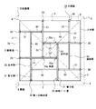
図1に示すように、第一の実施の形態においては、本発明にかかる小屋組構造を方形屋根1に適用している。
小屋組10は四本の枠用ベント梁20、斜め梁30(以下、「第一の斜め梁3030」という。)及び連結梁40を有している。
【0026】
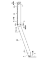
枠用ベント梁20とは、図1及び図2に示すように、方形屋根1の裏面側において、建物の外壁2の上端部から屋根面3の傾斜方向に沿って斜め上方に、該屋根面3の左右の隅棟4のうちの一方の隅棟部分にまで至るように配置される登り部21と、該登り部21の隅棟4側の端部から、該隅棟4を挟んで隣接する他の屋根面3の傾斜方向に対して直交すると共に水平に延出し、該屋根面3の他方の隅棟部分にまで至る水平部22とを備える部材である。
なお、屋根面3の傾斜方向とは、屋根面3の下端縁3aに直交し、かつ、屋根面3の傾斜角と同じ傾斜角を有する方向である。そして、登り部21と水平部22は、例えば、H型鋼等からなり、登り部21と水平部22とを平面視した場合に一直線になるように、その一端部において相互に、例えば、溶接等の手段により突き合わせ溶接されている。
【0027】
各枠用ベント梁20の水平部22側の端部は、該枠用ベント梁20に直交するように配置される他の枠用ベント梁20の水平部22に、各枠用ベント梁20の水平部22が同一高さとなるように、梁受け金物5を介して取り付けられる。そして、枠用ベント梁20の登り部21側の端部は住宅の外壁2の上端部に、梁受け金物6を介して取り付けられる。なお、外壁2の上端部には補強用の合板7等が取り付けられ、その合板7上に前記梁受け金物6が接合される。
そして、該枠用ベント梁20の登り部21には、後述する第一の斜め梁30及び連結梁40が、該登り部21に対し直交して取り付けられる。
【0028】
このようにして四つの隅棟4をそれぞれ通る四本の枠用ベント梁20同士が互いに接合されることで、各枠用ベント梁20の水平部22が四角枠状に配置されると共に、四本の枠用ベント梁20の水平部22からなる四角枠の四つの角部20aから四つの各屋根面3の勾配方向に沿って下方に、各枠用ベント梁20の登り部21が外壁2の上端部まで延出した状態となる。
【0029】
なお、枠用ベント梁20の登り部21及び水平部22のウェブ21a,22aには、長さ方向に沿って、予め決められた間隔で設けられる複数個の孔23aからなる接合部23が多数設けられている。(図2においては1つのみ示す。)この接合部23は、梁受け金物5を介して他の枠用ベント梁20の水平部22側の端部と接合したり、後述する第一の斜め梁30及び連結梁40の端部を接合するために設けられている。また、接合部23同士の間隔が、設計時に各梁の配置を決める際に用いられる基準寸法の整数分の一もしくはその整数倍となるように決められており、上記基準寸法に基づいて配置された梁を接合できるようになっている。
【0030】
第一の斜め梁30とは、その両端部において、4本の枠用ベント梁20の登り部21のウェブ21aや、外壁2の上端部と接合することによって、小屋組10の強度や安定性などを高めるための部材である。
第一の斜め梁30は、前記枠用ベント梁20と同様に、建物の外壁2の上端部に図示しない梁受け金物を介して取付けられ、屋根面3の傾斜方向に沿って斜め上方に、該屋根面3の左右の隅棟4のうち、前記枠用ベント梁20の登り部21が配置されていない側の隅棟部分にまで至るように配置される登り部31を備える。そして、登り部31の隅棟4側の端部から、該隅棟4を挟んで隣接する他の屋根面3の傾斜方向に対して直交すると共に水平に延出し、該屋根面3に登り部21が配置されている枠用ベント梁20に図示しない梁受け金物5を介して接合する水平部32を備えている。そして、これら登り部31と水平部32は、例えば、H型鋼等からなり、登り部31と水平部32とを平面視した場合に一直線になるように、その一端部において相互に、例えば、溶接等の手段により突き合わせ溶接されている。
なお、第一の斜め梁30のウェブにも、長さ方向に沿って、枠用ベント梁20と同様の接合部が多数設けられている。
【0031】
連結梁40とは、例えば、H型鋼等からなる直線状の部材である。そして、連結梁40は、各屋根面3の裏側において、該屋根面3の傾斜方向に直交するように水平に配置されると共に、その両端部において、該屋根面3を支持している枠用ベント梁20の登り部21や該枠用ベント梁20と平面視した場合に平行に配置されている第一の斜め梁30と接合することで、小屋組10の強度と安定性を高めるために用いられる。
なお、第一の実施の形態においては図1に示すように、一つの屋根面3について、一本の連結梁40が配置されている。そして、各連結梁40は、枠用ベント梁20の登り部21と該登り部21に対して直交して取り付けられる第一の斜め梁30の水平部32との接合部分から延出するように、かつ、平面視した場合に該第一の斜め梁30と一直線となるように設けられる。
【0032】
このように、四つの隅棟4をそれぞれ通る四本の第一の斜め梁30と四本の連結梁40とから形成される4本の直線同士が互いに接合されることで、各第一の斜め梁30の水平部32と連結梁40とが形成する直線部分が四角枠状に形成されると共に、該四角枠の四つの角部から四つの各屋根面3の勾配方向に沿って各第一の斜め梁30の登り部31が外壁2の上端部まで延出した状態となる。
【0033】
上述のように各梁を配置することで、枠用ベント梁20の水平部22が形成する四角枠の一辺から延出するように設けられる枠用ベント梁20の登り部21と、第一の斜め梁30の水平部32と連結梁40とが形成する四角枠の一辺から延出するように設けられる第一の斜め梁30の登り部31が、各屋根面3を左右にほぼ二等分する中心線を挟むように位置することになる。従って、小屋組10に対して上方から荷重がかかった場合に、枠用ベント梁20を回転させようとする力に対して、第一の斜め梁30の水平部32と連結梁40とが形成する直線部分には、前記枠用ベント梁20を逆方向に回転させようとする力が働くので、小屋組10全体の強度と安定性をより高めることができる。
なお、後述するように、小屋組10の基本構造を、四角枠状に接合された枠用ベント梁20の水平部22と、該四角枠の四隅20aから外壁2の上端部まで延出する枠用ベント梁20の登り部21とから構成されるものとすることで、建物の最上階の床面上A1において、この小屋組10の基本構造となる部分を構築し、それを上方に吊り上げて外壁の上端部に設置することができ、小屋組の施工性が向上する。
【0034】
なお、第一の実施の形態においては、各屋根面3に第一の斜め梁30の登り部31が一つずつ配置されるものとしているが、例えば、図3に示すように、各屋根面3に第一の斜め梁30の水平部32が2つずつ配置し、各水平部32から延出するように、複数本の連結梁40を直線状に配置して、四本の枠用ベント梁20の水平部22が形成する四角枠の外側に二重の四角枠を形成することにより、小屋組10の強度と安定性をより高めることができる。
なお、前記第一の斜め梁30の登り部31と水平部32の長さは、予め該第一の斜め梁30が配置される屋根面3の形状に対応するように設けられている。
また、図4に示すように、第一の斜め梁30を、屋根面3の左右をほぼ二等分する中心線に対して、枠用ベント梁20の登り部21が位置する側、つまり、平面視した場合に互いに平行な二本の第一の斜め梁30で枠用ベント梁20を挟むように配置することとしても良い。
【0035】
第一の実施の形態の小屋組10によれば、各梁同士がお互いを支持し合う構造となるので、従来において梁を支持するために必要であった、住宅内部のトラスや屋切りパネル(内壁)が必要無く、また、住宅の屋根裏が内壁にしきられることなく、屋根裏全体からなるひとつの小屋裏空間を構築することができる。
【0036】
また、従来のように、屋根内部の空間に内壁を用いた小屋裏構造においては、同じ形状及び大きさの屋根を有する住宅同士でも、住宅内部の間取りによって内壁の位置が異なるため、各住宅の内壁の位置に対応した小屋組を構築する必要があった。しかし、第一の実施の形態の小屋組10においては、屋根内部の空間に内壁が存在しないので、同じ形状及び大きさの屋根を有する住宅において、屋根を支持する小屋組10を変える必要が無くなる。従って、小屋組10を構成している各梁のサイズや長さを変えずに、同規格の梁をそのまま同じ形状及び大きさを有する他の屋根に使用できることになるので、同規格の梁及びそれらに付随して必要となる梁受け金物5等の各種部材が大量に生産できるようになり、コストの削減が可能となる。
【0037】
また、小屋組10を各棟に対して対称的な構造として、同じ規格の梁を多く使用して小屋組を構築することができるので、各部材を同一規格で大量に生産することになり、コストの削減が可能となる。
また、内壁が存在しないことにより、小屋組の設計の自由度が高まり、部材選択の自由度も高まるので、コスト的に最適な小屋組を設計することが可能となる。
【0038】
なお、上記第一の実施の形態の小屋組において、第一の斜め梁30や連結梁40の数を増やし、各梁同士の間隔を密にすることで、小屋組自体の強度を容易に高めることができ、例えば、多雪地域などにおいても、雪の重みにより屋根に加わる荷重に十分対応可能な程度に強度を高めることができる。
【0039】
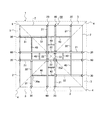
[第二の実施の形態]
図5に示すように、第二の実施の形態に示す小屋組50は、四本の枠用ベント梁20、斜め梁60(以下、「第二の斜め梁60」という。)及び連結梁40を備えている。
なお、枠用ベント梁20及び連結梁40については、第一の実施の形態で示した枠用ベント梁20及び連結梁40と略同一のものを使用するので詳しい説明は省略し、以下、主に第二の斜め梁60について説明する。
【0040】
第二の斜め梁60とは、例えばH型鋼等からなり、その両端部において水平部22が四角枠を形成するように接合された4本の枠用ベント梁20の水平部22及び外壁2の上端部と接合することによって、小屋組の強度や安定性などを高めるために用いられる部材である。
第二の実施の形態で用いる第二の斜め梁60は、第一の実施の形態で用いた第一の斜め梁30、つまり、登り部31と水平部32とを備える梁とは異なり、登り部のみ、つまり、建物の外壁2の上端部から該屋根面3の傾斜方向に沿って斜め上方に延出する直線梁のみを備える。そして、第二の斜め梁60の一方の端部は外壁2の上端部と図示しない梁受け金物を介して取付けられ、他方の端部は該第二の斜め梁60と直交するように配置されている前記枠用ベント梁20の水平部22と図示しない梁受け金物を介して取り付けられる。なお、第二の斜め梁60のウェブにも、長さ方向に沿って、枠用ベント梁20と同様の接合部が多数設けられている。
【0041】
各屋根面3に対して二本ずつ、平面視した場合に互いに平行に配置される第二の斜め梁60のうち、一方の第二の斜め梁60は、屋根面3を左右に二等分する中心線に対して、該屋根面3に配置されている前記枠用ベント梁20の登り部21と対称な位置、つまり、該屋根面3に対向する位置に在する屋根面3に登り部21が配置されている他の枠用ベント梁20と、平面視した場合に一直線となる位置に配置される。即ち、第二の斜め梁60の端部が枠用ベント梁20同士の隅棟4の接合部分で、枠用ベント梁20に接合される。
そして、他方の第二の斜め梁60は前記中心線上に配置される。
【0042】
連結梁40は、一つの屋根面3について、該屋根面3の傾斜方向に対して直交するように、二本の連結梁40が直線状に配置され、各連結梁40の両端部は枠用ベント梁20の登り部21または第二の斜め梁60に接合している。
【0043】
以上、第二の実施の形態にかかる小屋組50によれば、枠用ベント梁20の水平部22が形成する四角枠の一辺から延出するように設けられる枠用ベント梁20の登り部21と、該登り部21と平行に、かつ、屋根面の前記中心線上及び、前記中心線に対して前記登り部21と対称位置に配置される第二の斜め梁60とを備えることによって、小屋組50に対して上方から荷重がかかった場合に、枠用ベント梁20を回転させようとする力に対抗する位置に第二の斜め梁60が位置することになり、小屋組50の強度と安定性を高めることになる。
また、各屋根面3にかかる力を、該屋根面3に配置される枠用ベント梁20の登り部21と、二本の第二の斜め梁60とで均等に、かつ、効率よく外壁2に伝えることができるので、小屋組50の強度と安定性をより高めることができる。
【0044】
なお、図6に示すように、第一の実施の形態で示した第一の斜め梁30と、第二の実施の形態で示した第二の斜め梁60とを同時に使用して小屋組50を構築するものとしてもよい。即ち、第一の実施の形態で示したように、第一の斜め梁30を枠用ベント梁20の登り部21に、該登り部21に対して直角に接合し、更に、その接合部分から延出するように、平面視した場合に該第一の斜め梁30と一直線となるように二本の連結梁40を接合する。そして、これら第一の斜め梁30と二本の連結梁40とからなる直線同士を互いに接合することで、各第一の斜め梁30の水平部32と二本の連結梁40とが形成する直線部分が四角枠状に配置されると共に、該四角枠の四つの角部30aから四つの各屋根面3の勾配方向に沿って各第一の斜め梁30の登り部31が外壁2の上端部まで延出した状態となる。
そして、第二の実施の形態で示したように、第二の斜め梁60を、屋根面3を左右に二等分する中心線に対して、該屋根面3に配置されている枠用ベント梁20の登り部21と対称な位置、つまり、該屋根面3に対向する位置に在する屋根面3に登り部21が配置されている他の枠用ベント梁20と、平面視した場合に一直線となる位置に配置する。
【0045】
このように第一の斜め梁30と第二の斜め梁60とを用いて小屋組50を構築することで、上記第一の実施の形態及び第二の実施の形態で示した小屋組と同様の効果を奏することができる。
【0046】
なお、本発明は上記実施の形態例に限定されるものではなく、本発明の要旨の範囲内で種々の変形実施が可能である。例えば、ベント梁は、H型鋼のみならず、I型、コ字状型、または、管状の鋼材でも良く、さらに、その他の材料、たとえば木材でもよい。
また、屋根の形状は、上記実施の形態に示した方形屋根1に限らず、寄棟屋根や、その他、屋根の基本形状として、屋根の中央部から四方に流れる四つの屋根面を有するものであれば本発明を適用できる。
また、上記実施の形態は、パネル工法によって構築され、方形屋根1を屋根の基本構造とする建物に本発明を適用したものであるが、木造軸組構造や、壁式鉄筋コンクリート構造、鉄骨ラーメン構造など、パネル工法以外の構造形式により構築される建物にも本発明を適用できる。
【0047】
なお、各梁同士、及び各梁と外壁との接合は上述のように、梁受け金物を介して例えば、ボルトナットで締結し固定することで行なわれるものとしたが、その他、プレートを用いた溶接方法など、周知の方法によって接合されるものとしてもよい。
また、枠用ベント梁20の水平部22、第一の斜め梁30の水平部32の上面には、結合桁24が取り付けられる(図2を参照)。結合桁24は支持する屋根の勾配に対応した傾斜を各梁の上面に形成するための部材である。従って各梁は、その上面において、各梁が支持する屋根面の勾配に合わせた傾斜面を有することになる。
【0048】
次に、本発明にかかる小屋組の構築方法について説明する。
なお、以下の説明においては、図7及び図11に示すように、方形屋根1を基本構造とする屋根を有する二階建ての建物Aの二階の屋根部分に小屋組を構築し、該小屋組上に予め工場において製作される木製のパネル8aを配設していくものとする。
【0049】
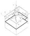
この小屋組の構築方法は、図7および図8に示すように、建物Aの最上階の上方に設置される小屋組のうち前記枠用ベント梁20から構成される部分を、建物Aへの取付向きに対して右周りに略30度角度をずらした向きで、かつ、前記小屋組を支持する壁パネルA2にほぼ直接取付可能な形状に、前記二階の床面A1上において組み立てる組立工程と、図9に示すように、その向きを保ちつつ前記壁パネルA2への取付け高さまで鉛直上方に吊り上げる吊上工程及び前記壁パネルA2への取付向きまで左回りに略30度回転させる回転工程と、図10に示すように、前記壁パネルA2に取り付ける取付工程とから概略構成されている。
【0050】
ここで、前記組立工程は、図8に示すように、枠用ベント梁20の水平部22上に、該枠用ベント梁20によって支持される屋根面3よりも上方にある屋根面を構成する上部屋根パネル8bを取り付ける上部屋根パネル取付工程を含むものとする。
【0051】
上記組立工程においては、まず、四本の枠用ベント梁20を、建物Aの二階の床面A1上に搬入する。そして、これら枠用ベント梁20の水平部22側の端部を、他の枠用ベント梁20の水平部22のウェブ22aに、梁受金物5を介して直角に締結する。
この際、図7に示すように、上記枠用ベント梁20によって構成される小屋組の一部が、前記建物Aへの取付向きに対して右周りに略30度角度をずらした向きになるようにする。
【0052】
そして、図8に示すように、前記枠用ベント梁20の水平部22の上に設けられた結合桁24の上に、略ピラミッド形状になるように4枚の前記上部屋根パネル8bを載置し、これら上部屋根パネル8bの隣接部を釘および接着剤により互いに固定するとともに、各上部屋根パネル8bの下端部を前記結合桁24に、釘および接着剤により固定する。
【0053】
次いで、図9に示すように、4本の前記枠用ベント梁20の水平部22によって形成される四角枠の4つの角部20a近傍、すなわち、各枠用ベント梁20の水平部22と登り部21との接合部分の近傍を、吊上用のケーブルBに固定し、互いに接合された4本の枠用ベント梁20を、その向きを保ちつつ前記壁パネルA2への取付高さまで、図示しないクレーンによって鉛直上方に吊り上げる。
【0054】
そして、前記クレーンによって前記壁パネルA2への取付高さに吊り上げられた状態で、互いに接合された4本の枠用ベント梁20を、左周りに略30度回転させて、前記壁パネルA2への取付向きに合わせる。
【0055】
最後に、図10に示すように、各枠用ベント梁20の登り部21の端部を、前記壁パネルA2に梁受金物6を介してボルトにより締結する。
【0056】
このように、四角枠を形成するように接合された枠用ベント梁20を壁パネルA2に取付けた後、第一及び第二の実施の形態で示した斜め梁30,60や連結梁40などを取付けることで小屋組が構築される。
なお、クレーンによる吊り上げが可能な範囲内において、予め床面A1上において斜め梁30,60や連結梁40などを取り付けておくものとしてもよい。
【0057】
そして、小屋組の取付が終了したら、前記上部屋根パネル8bを足場として、該上部屋根パネル8bの周囲の屋根面を構成する他の屋根パネル8a(図11では一枚のみ図示)を、前記枠用ベント梁20と壁パネルA2の間に順次取り付ける。
なお、図11に示すように、屋根の基本構造である方形屋根の屋根面3から側方に突出する切妻屋根部分については、四本の枠用ベント梁20のうち一本の枠用ベント梁20と壁パネルA2との間に棟木41を取り付けた上で、屋根パネル8aを配置する。
【0058】
以上、本実施の形態の小屋組の構築方法によれば、前記組立工程において、小屋組を、前記最上階の床面A1(二階の床面A1)上に収まるように前記建物Aへの取付向きに対して左右いずれかに角度をずらした向きで、かつ、前記小屋組を支持する支持部材(壁パネルA2)にほぼ直接取付可能な形状に、前記最上階の床面A1上において組み立てる。従って、高い安全性および作業性を確保できる床面A1上において、小屋組を支持部材にほぼ直接取付可能な形状に組み立てるので、該組立工程における高所作業を削減することができる。
また、建物が密集する地区内に建物Aを建設する場合など、建物Aの外側に小屋組を組み立てるための作業スペースを確保することが難しい場合にも、本小屋組の構築方法を適用することができる。
また、前記小屋組を、組立工程において前記壁パネルA2にほぼ直接取付可能な形状に組み立てた上で、吊上工程および回転工程において前記壁パネルA2への取付高さおよび取付向きまで移動し、取付工程において前記壁パネルA2に取り付けるので、小屋組の施工に要する手間が削減され、工期の短縮を図ることができる。
【0059】
また、枠用ベント梁20の水平部22及び斜め梁の水平部22の上面には、これら梁によって支持される前記屋根面3と平行な上面を有する結合桁24が設けられているので、該結合桁24の上に、前記屋根面を構成する屋根パネル8aを載置して固定することで、前記屋根パネル8aを簡便かつ確実に取り付けることができる。
【0060】
また、前記組立工程は、前記枠用ベント梁20の水平部22の上に、該水平部22によって前記屋根面3が支持される高さ位置よりも上部の屋根面を構成する上部屋根パネル8bを取り付ける上部屋根パネル取付工程を含む。従って、高い安全性および作業性を確保できる前記二階の床面A1上において、前記枠用ベント梁20の水平部22の上に、前記上記屋根パネル8bを取り付けることができ、前記小屋組の上に屋根パネル8bを取り付ける高所作業の一部を省略できる。また、前記上部屋根パネル8bの周囲の屋根面を構成する他の屋根パネルを取り付ける際に、前記組立工程において予め取り付けられた上部屋根パネルを足場として利用することができる。従って、前記他の屋根パネルの取付作業を簡便に行うことができる。
【0061】
【発明の効果】
請求項1記載の小屋組構造によれば、住宅の屋根裏が内壁にしきられることなく、屋根裏全体からなるひとつの小屋裏空間を構築することができる。また、同規格の梁及びそれらに付随して必要となる梁受け金物5等の各種部材が大量に生産できるようになり、コストの削減が可能となる。また、内壁が存在しないことにより、小屋組の設計の自由度が高まり、部材選択の自由度も高まるので、コスト的に最適な小屋組を設計することが可能となる。また、小屋組の強度と安定性を高めることができる。また、建物の最上階の床面上において、小屋組の基本構造となる部分を構築し、それを上方に吊り上げて外壁の上端部に設置することができる。従って、小屋組の施工性が向上する。また、斜め梁が枠用ベント梁の回転を抑える効果を有することになり、小屋組の強度と安定性を高めることができる。また、各屋根面にかかる荷重を枠用ベント梁の登り部と斜め梁によって効率的に外壁に伝えることができる。
また、小屋組構造の強度をより高めることができる。
さらに、高所作業を削減し、高い安全性および作業性を確保できる。また、建物Aの外側に小屋組を組み立てるための作業スペースを確保することが難しい場合でも本小屋組の構築方法を適用することができる。また、小屋組の施工に要する手間が削減され、工期の短縮を図ることができる。
【0062】
請求項2記載の小屋組構造によれば、請求項1と同様の効果を得られると共に、前記強度向上用の斜め梁を配置することによって、小屋組自体の強度を高めることができる。
【0063】
請求項3記載の小屋組構造によれば、請求項1または2と同様の効果を得られると共に、枠用ベント梁20を回転させようとする力に対抗する位置に斜め梁60が位置することになり、小屋組構造10の強度と安定性をより高めることができる。
【0066】
請求項4記載の小屋組の構築方法によれば、請求項1〜3と同様の効果を得られると共に、高所作業を削減し、高い安全性および作業性を確保できる。また、建物Aの外側に小屋組を組み立てるための作業スペースを確保することが難しい場合でも本小屋組の構築方法を適用することができる。また、小屋組の施工に要する手間が削減され、工期の短縮を図ることができる。
【図面の簡単な説明】
【図1】第一の実施の形態の小屋組構造10を示す平面図である。
【図2】枠用ベント梁20の構造を示す側面図である。
【図3】小屋組構造の一例を示す平面図である。
【図4】小屋組構造の一例を示す平面図である。
【図5】第二の実施の形態の小屋組構造50を示す平面図である。
【図6】小屋組構造の一例を示す平面図である。
【図7】小屋組構造の構築方法を示す斜視図である。
【図8】小屋組構造の構築方法を示す斜視図である。
【図9】小屋組構造の構築方法を示す斜視図である。
【図10】小屋組構造の構築方法を示す斜視図である。
【図11】小屋組構造の構築方法を示す平面図である。
【符号の説明】
1 方行屋根
3 屋根面
4 隅棟
10 小屋組
20 枠用ベント梁
21 登り部
22 水平部
30 第一の斜め梁
31 登り部
32 水平部
40 連結梁
50 小屋組
60 第二の斜め梁[0001]
BACKGROUND OF THE INVENTION
The present invention is a hut that can perform assembling work of a hut group exclusively inside the outer wall line of a building and can improve workability of assembling work by reducing work at a high place and can obtain a wide shed space. The present invention relates to a structure of a set and a structure of a hut set.
[0002]
[Background technology]
In general, a panel construction method is known in which a house is constructed by installing panels manufactured in advance in a factory or the like with respect to floors, walls, roofs and the like at a construction site.
In the above panel construction method, the panels that make up the floor, walls, roof, etc. are joined together to form the house, so it is basically made of few columns and beams, but only the wall panels. Because it is difficult to support all the roof panels that make up the roof, beams that support the roof are used. And as a roof supporting beam for indicating the lower surface of a gable roof or the like provided in a panel construction house, a straight beam made of wood, H-shaped steel or the like is usually used.
[0003]
As described above, for example, in a roof structure using a straight beam as a roof supporting beam for a gable roof provided in a panel construction house, usually, a truss is provided above at least a part of a wall panel in the house. Yaiya panel (hereinafter referred to as the inner wall) is provided so as to reach the back side of the roof, and the upper ends thereof are joined to the roof. Then, one end of the straight beam is joined to the upper end of the outer wall, the other end is joined to the upper end of the inner wall, or both ends of the straight beam are joined to the upper end of the inner wall. Both ends are supported. A plurality of such linear beams are arranged along the inclined surface of the roof, thereby forming a roof structure for supporting the entire roof.
[0004]
According to the above-mentioned roof structure, there is no beam or bundle supporting the straight beam below the straight beam arranged along the back side of the roof, so the roof space on the back side of the roof is made relatively wide. The roof space can be effectively used by raising the ceiling or providing a room for storing a large attic in the attic.
[0005]
Further, as a roof support beam for supporting the lower surface of a dormitory roof (including a square roof) provided in a panel construction house, for example, a so-called vent as disclosed in JP-A-8-74370 Beams are used.
The bent beam has a climbing portion arranged obliquely and a horizontal portion arranged horizontally, and the climbing portion and the horizontal portion are joined to each other at one end portion thereof, and are bent at the joint portion. This is the beam.
[0006]
In the roof structure using the bent beam, at least a part of the inner wall of the house is provided so as to reach the back side of the roof, and the upper end portion of the inner wall is joined to the roof. And, the end of the climbing part of the bent beam is joined to the upper end of the outer wall, and the end of the horizontal part is joined to the upper end of the inner wall, thereby supporting the plurality of bent beams and supporting the entire roof. A cabin structure is formed.
[0007]
In the roof structure using a bent beam, similarly to the above-described structure using a straight beam, a beam or a bundle supporting the bent beam is provided below the vent beam arranged along the back side of the roof. Since it does not exist, the attic space on the back side of the roof can be made relatively wide, the ceiling is raised, and a room for storing the attic is installed in the attic to make the attic space effective Can be used.
[0008]
[Problems to be solved by the invention]
By the way, the above-described roof structure has an inner wall provided so as to reach the roof to support the roof and the beam. For example, the attic of the house is completely covered with the inner wall, and one hut consisting of the entire attic is formed. The use of the back space is restricted, such as the inability to build a back space. Therefore, there is a demand for a cabin structure that can use the entire attic as a single attic space.
[0009]
In addition, since the construction of the hut as described above is performed at a high place, it takes time and labor for the construction. After the hut is assembled on the ground beforehand, it is lifted with a crane or the like and attached to the building. There is a way to reduce the work at.
However, in an urban area or the like, a building that uses almost the entire surface of the site is often constructed in order to effectively use the land. Therefore, it is difficult to secure a room for assembling the hut assembly on the ground outside the building to be constructed. In addition, a method of transporting to a building construction site after pre-assembling a cabin set in a place outside the site is also conceivable. However, since the assembled hut has a plane dimension approximately equal to or exceeding the plane of the building, it is difficult to transport it to the building construction site using a narrow road in an urban area.
[0010]
The object of the present invention is to take the above-mentioned circumstances into consideration, and to improve the workability of the assembly work by performing the assembly work of the cabin exclusively inside the outer wall line of the building and reducing the work at high places. At the same time, the present invention is to provide a hut structure and a method for constructing the shed that can provide a wide shed space.
[0011]
[Means for Solving the Problems]
In order to solve the above problems, the roof structure according to
Each of the four roof surfaces (3) is horizontally disposed below the horizontal portion (22) of the frame bent beam (20), and the left and right end portions thereof are the frame bent beam (20). Alternatively, a connecting beam (40) joined to the diagonal beam (30, 60) is provided.
At least a part of the oblique beam (30) is a bent beam including an ascending portion (31) and a horizontal portion (32) connected to the ascending portion (31) at the corner ridge (4) portion, and the oblique beam The horizontal portion (32) of the beam (30) and the connecting beam (40) are arranged at the same height, and the horizontal portion (22) of the oblique beam (30) and the connecting beam (40) Arranged to be a square frameIt is characterized by that.
[0012]
According to the roof structure of
[0013]
In addition, since there is no inner wall in the space inside the roof, it is not necessary to change the hut set (10, 50) that supports the roof in a house having a roof of the same shape and size. Therefore, the beam of the same standard can be used as it is for another roof having the same shape and size without changing the size and length of each beam constituting the roof group (10, 50). Various members such as standard beams and beam receiving hardware (5, 6) necessary for the beams can be produced in large quantities, and the cost can be reduced.
[0014]
Further, since the hut assembly (10, 50) can be constructed symmetrically and the shed assembly (10, 50) can be constructed using many beams of the same standard, each member is produced in large quantities with the same standard. As a result, the cost can be reduced. In addition, since there is no inner wall, the degree of freedom in designing the hut assembly (10, 50) is increased, and the degree of freedom in selecting members is also increased. Therefore, the optimum hut assembly (10, 50) can be designed in terms of cost. It becomes possible. In addition, the basic structure of the hut assembly (10, 50) is composed of a horizontal part (22) of the frame bent beam (20) joined in a square frame shape, and the outer wall (2) from the four corners (20a) of the square frame. It is composed of the climbing part (21) of the frame bent beam (20) extending to the upper end part, so that this hut assembly (A1) on the floor (A1) on the top floor of the building (A) 10, 50) can be constructed, and it can be lifted upward and installed at the upper end of the outer wall (2). Therefore, the workability of the hut assembly is improved. When the basic structure of the cabin set (10, 50) is the above-described structure, when a load is applied to the cabin set (10, 50) from above, the cabin set (10, 50) A force to rotate the frame bent beam (20) that constitutes the frame acts on the diagonal beam (30, 60) by joining the diagonal beam (30, 60) to the frame bent beam (20). (30, 60) has the effect of suppressing the rotation of the frame bent beam (20), and the strength and stability of the cabin set (10, 50) can be increased. Moreover, the load concerning each roof surface (3) can be efficiently transmitted to an outer wall by the climbing part (21) and the diagonal beam (22) of the bent beam for frames (20).
Moreover, the intensity | strength of a hut (10, 50) can be raised more.
Further, when a load is applied from above the roof set (10, 50), the horizontal portion (32) of the diagonal beam (30) against the force to rotate the frame vent beam (20). Since the force which tries to rotate the said bent beam (20) for a frame acts on the straight part which a connection beam (40) forms, the intensity | strength and stability of the whole roof group (10,50) Can be further enhanced.
[0015]
The roof structure according to
The diagonal beam (30) is different from the diagonal beam (30) in which the climbing portion (31) is disposed on the other roof surface portion, and the corners are formed on the climbing portion (21) and the climbing portion (21). The horizontal portion (32) of the oblique beam (30) for improving the strength, which is a bent beam having a horizontal portion (32) connected at the ridge (4) portion, is a horizontal portion (22) of the frame bent beam (20). ) And one end portion is joined to the climbing portion (21) of the frame bent beam (20), and the climbing portion (31) of the diagonal beam (30) for improving the strength is the roof. It arrange | positions at the roof surface (3) part of one side of a surface (3), It is characterized by the above-mentioned.
[0016]
According to the roof structure of
[0017]
The roof structure according to
[0018]
According to the roof structure of
[0023]
Claim4The construction method of the set of huts described in
[0024]
Claim4According to the construction method of a set of huts (10, 50) as described3As well as assembling the roof set (10, 50) on the top floor (A1) by the assembling process, the work at a high place is reduced, and high safety and workability are achieved. It can be secured. Further, even when it is difficult to secure a work space for assembling the hut assembly (10, 50) outside the building (A), the construction method of the shed assembly can be applied. In addition, the hut assembly (10, 50) is assembled in advance in a shape that can be attached almost directly to the wall panel (A2) in the assembly process, and then is attached to the wall panel (A2) in the lifting process and the rotation process. Since it moves to the mounting height and mounting direction and is mounted on the wall panel (A2) in the mounting process, the labor required for the construction of the hut assembly (10, 50) is reduced, and the construction period can be shortened.
[0025]
DETAILED DESCRIPTION OF THE INVENTION
Hereinafter, embodiments of the present invention will be described in detail with reference to the drawings.
[First embodiment]
As shown in FIG. 1, in the first embodiment, the roof structure according to the present invention is applied to a
The
[0026]
As shown in FIG. 1 and FIG. 2, the frame bent
The inclination direction of the
[0027]
The end of each
A
[0028]
In this way, the four frame
[0029]
The climbing
[0030]
The first
The first
The web of the first
[0031]
The connecting
In the first embodiment, as shown in FIG. 1, one connecting
[0032]
In this way, the four straight lines formed by the four first oblique beams 30 and the four connecting
[0033]
By arranging each beam as described above, the climbing
As will be described later, the basic structure of the cabin set 10 includes a
[0034]
In the first embodiment, the climbing
The lengths of the climbing
Also, as shown in FIG. 4, the
[0035]
According to the roof set 10 of the first embodiment, each beam supports each other, and thus, a truss or a house-cutting panel (in-house) that is conventionally required to support the beam ( It is possible to construct a single attic space consisting of the entire attic without the need for an inner wall) and without having the attic of the house completely covered by the inner wall.
[0036]
In addition, in the hut back structure using the inner wall in the space inside the roof as in the past, the position of the inner wall differs depending on the floor plan inside the house, even between houses having roofs of the same shape and size. It was necessary to build a cabin set corresponding to the position of the inner wall. However, in the roof set 10 of the first embodiment, since the inner wall does not exist in the space inside the roof, it is not necessary to change the roof set 10 that supports the roof in a house having a roof of the same shape and size. . Therefore, the beam of the same standard can be used as it is for another roof having the same shape and size without changing the size and length of each beam constituting the roof set 10, and Various members such as the
[0037]
In addition, since the
Further, since there is no inner wall, the degree of freedom in designing the hut assembly is increased, and the degree of freedom in selecting members is also increased, so that it is possible to design an optimum hut assembly in terms of cost.
[0038]
In the cabin set of the first embodiment, the strength of the cabin set can be easily increased by increasing the number of the first
[0039]
[Second Embodiment]
As shown in FIG. 5, the cabin set 50 shown in the second embodiment includes four frame bent beams 20, diagonal beams 60 (hereinafter referred to as “second
Note that the frame bent
[0040]
The second
The second
[0041]
Of the second
The other second
[0042]
As for the connecting
[0043]
As described above, according to the cabin set 50 according to the second embodiment, the climbing
In addition, the
[0044]
In addition, as shown in FIG. 6, the first
Then, as shown in the second embodiment, the second
[0045]
In this way, by constructing the cabin set 50 using the first
[0046]
The present invention is not limited to the above embodiment, and various modifications can be made within the scope of the gist of the present invention. For example, the bent beam may be not only H-shaped steel but also I-shaped, U-shaped, or tubular steel materials, and may be other materials such as wood.
Moreover, the shape of the roof is not limited to the
Moreover, although the said embodiment is constructed by the panel construction method and applies this invention to the building which uses the
[0047]
In addition, although it was assumed that each beam and each beam and the outer wall were joined by fastening with, for example, bolts and nuts via a beam receiver as described above, a plate was also used. It is good also as what is joined by well-known methods, such as a welding method.
Further, a
[0048]
Next, a method for constructing a cabin according to the present invention will be described.
In the following description, as shown in FIG. 7 and FIG. 11, a hut assembly is constructed on the second-floor roof portion of a two-story building A having a roof having a
[0049]
As shown in FIGS. 7 and 8, this building method for building a roof set is a part of the roof set installed above the uppermost floor of the building A, and the portion composed of the frame bent
[0050]
Here, as shown in FIG. 8, the assembling step forms a roof surface above the
[0051]
In the assembly process, first, the four frame vent beams 20 are carried onto the floor A1 on the second floor of the building A. Then, the end of the frame bent
At this time, as shown in FIG. 7, a part of the cabin set constituted by the frame bent
[0052]
Then, as shown in FIG. 8, on the connecting
[0053]
Next, as shown in FIG. 9, the vicinity of the four
[0054]
Then, in a state where the crane is lifted to the mounting height to the wall panel A2, the four frame
[0055]
Finally, as shown in FIG. 10, the end of the climbing
[0056]
Thus, after attaching the frame bent
In addition, within the range which can be lifted with a crane, it is good also as what attaches the
[0057]
When the installation of the hut is finished, the other roof panel 8a (only one is shown in FIG. 11) constituting the roof surface around the
In addition, as shown in FIG. 11, about the gable roof part which protrudes sideways from the
[0058]
As described above, according to the construction method of the hut assembly of the present embodiment, in the assembling step, the hut assembly is attached to the building A so as to fit on the top floor A1 (second floor A1). It is assembled on the top surface A1 of the uppermost floor in a direction that is shifted to the left or right with respect to the direction and that can be mounted almost directly on the support member (wall panel A2) that supports the hut assembly. Therefore, since the roof assembly is assembled into a shape that can be almost directly attached to the support member on the floor surface A1 where high safety and workability can be ensured, it is possible to reduce work at high places in the assembly process.
In addition, if it is difficult to secure a work space for assembling the hut on the outside of the building A, such as when building A is built in an area where the buildings are densely packed, the method for constructing the shed is applied. Can do.
Further, after assembling the hut assembly into a shape that can be directly attached to the wall panel A2 in the assembly process, the hut assembly is moved to the height and direction of attachment to the wall panel A2 in the lifting process and the rotation process, Since it attaches to said wall panel A2 in an attachment process, the effort which construction of a hut assembly is reduced can reduce a work period.
[0059]
Further, the upper surface of the
[0060]
In the assembling step, the
[0061]
【The invention's effect】
According to the hut assembly structure of the first aspect, it is possible to construct a single attic space consisting of the entire attic without the attic of the house being covered by the inner wall. Further, it becomes possible to mass-produce various members such as the beams of the same standard and the
Moreover, the strength of the roof structure can be further increased.
Furthermore, work at high places can be reduced, and high safety and workability can be secured. Even if it is difficult to secure a work space for assembling the hut on the outside of the building A, the construction method of the shed can be applied. In addition, the labor required for the construction of the cabin is reduced, and the construction period can be shortened.
[0062]
According to the structure of the roof structure of the second aspect, the same effect as that of the first aspect can be obtained, and the strength of the roof structure itself can be increased by arranging the oblique beam for improving the strength.
[0063]
According to the roof structure of
[0066]
Claim4According to the construction method of a set of huts described in
[Brief description of the drawings]
FIG. 1 is a plan view showing a
FIG. 2 is a side view showing the structure of a frame bent
FIG. 3 is a plan view showing an example of a cabin structure.
FIG. 4 is a plan view showing an example of a cabin structure.
FIG. 5 is a plan view showing a
FIG. 6 is a plan view showing an example of a cabin structure.
FIG. 7 is a perspective view showing a method for constructing a cabin structure.
FIG. 8 is a perspective view showing a method for constructing a cabin structure.
FIG. 9 is a perspective view showing a method for constructing a cabin structure.
FIG. 10 is a perspective view showing a method for constructing a cabin structure.
FIG. 11 is a plan view showing a method for constructing a cabin structure.
[Explanation of symbols]
1-way roof
3 Roof surface
4 corner building
10 hut set
20 Bent beam for frame
21 climbing club
22 Horizontal part
30 First diagonal beam
31 climbing club
32 Horizontal part
40 connecting beams
50 huts
60 Second diagonal beam
Claims (4)
前記四つの屋根面のうちの一つの屋根面の下端部側から該屋根面の傾斜方向に沿って斜め上方に該屋根面の左右の隅棟のうちの一方の隅棟にまで至る登り部と、該登り部の前記一方の隅棟側の端部から前記屋根面に隣接する屋根面の傾斜方向と直交するように水平に延出する水平部とを有するベント梁を備え、
前記ベント梁には、四つの前記屋根面にそれぞれ一本ずつ互いに同じ高さ位置に前記水平部が配置されるとともに、各隅棟で隣接する隣の屋根面の水平部と接合されて四本の水平部が四角枠状に配置され、かつ、各屋根面の中央より左側の屋根面部及び右側の屋根面部のうちの一方側の屋根面部のみに前記四本の水平部にそれぞれつながる四本の登り部が配置される四本の枠用ベント梁が含まれ、
前記ベント梁の前記水平部と前記登り部とのうちの少なくとも登り部を有する斜め梁が備えられるとともに、前記斜め梁の登り部が前記屋根面の他方側の屋根面部に配置されるとともに、前記斜め梁の上側の端部が前記枠用ベント梁に接合され、
四つの前記屋根面のそれぞれに、前記枠用ベント梁の水平部より下側に水平に配置されるとともに、左右の端部が前記枠用ベント梁もしくは斜め梁に接合される連結梁を備え、
前記斜め梁のうちの少なくとも一部が登り部と該登り部に前記隅棟部でつながる水平部とを備えるベント梁とされ、前記斜め梁の水平部と前記連結梁とが同じ高さ位置に配置されるとともに、これら斜め梁の水平部と前記連結梁とが四角枠状となるように配置されていることを特徴とする小屋組構造。Like the dormitory roof and square roof, the basic structure of the roof has four roof surfaces that flow in all directions from the center, and supports the roof where the boundary between each roof surface excluding the ridge is a corner ridge on the lower side A hut structure
An ascending portion extending from the lower end side of one of the four roof surfaces to one corner ridge of the left and right corner ridges obliquely upward along the inclination direction of the roof surface; A bent beam having a horizontal portion extending horizontally from the end portion of the one corner ridge side of the climbing portion so as to be orthogonal to the inclination direction of the roof surface adjacent to the roof surface,
In the bent beam, the horizontal portion is arranged at the same height position on each of the four roof surfaces, and is joined to the horizontal portion of the adjacent roof surface adjacent to each corner building. Are arranged in a square frame shape and are connected to the four horizontal portions only to the roof surface portion on one side of the roof surface portion on the left side and the roof surface portion on the right side from the center of each roof surface. Includes four frame bent beams where climbing parts are placed,
An oblique beam having at least an ascending portion of the horizontal portion and the ascending portion of the bent beam is provided, and an ascending portion of the oblique beam is disposed on the roof surface portion on the other side of the roof surface, and The upper end of the diagonal beam is joined to the frame bent beam,
Each of the four roof surfaces includes a connecting beam that is horizontally disposed below a horizontal portion of the frame bent beam and whose left and right ends are joined to the frame bent beam or the diagonal beam,
At least a part of the oblique beam is a bent beam including an ascending portion and a horizontal portion connected to the ascending portion at the corner ridge portion, and the horizontal portion of the oblique beam and the connecting beam are at the same height position. A hut assembly structure in which the horizontal portions of the diagonal beams and the connecting beams are arranged in a square frame shape .
前記四つの屋根面のうちの一つの屋根面の下端部側から該屋根面の傾斜方向に沿って斜め上方に該屋根面の左右の隅棟のうちの一方の隅棟にまで至る登り部と、該登り部の前記一方の隅棟側の端部から前記屋根面に隣接する屋根面の傾斜方向と直交するように水平に延出する水平部とを有するベント梁を備え、
前記ベント梁には、四つの前記屋根面にそれぞれ一本ずつ互いに同じ高さ位置に前記水平部が配置されるとともに、各隅棟で隣接する隣の屋根面の水平部と接合されて四本の水平部が四角枠状に配置され、かつ、各屋根面の中央より左側の屋根面部及び右側の屋根面部のうちの一方側の屋根面部のみに前記四本の水平部にそれぞれつながる四本の登り部が配置される四本の枠用ベント梁が含まれ、
前記ベント梁の前記水平部と前記登り部とのうちの少なくとも登り部を有する斜め梁が備えられるとともに、前記斜め梁の登り部が前記屋根面の他方側の屋根面部に配置されるとともに、前記斜め梁の上側の端部が前記枠用ベント梁に接合され、
前記他方の屋根面部に前記登り部が配置された斜め梁とは別の斜め梁で、かつ、前記登り部と該登り部に前記隅棟部でつながる水平部とを備えるベント梁とされた強度向上用の斜め梁の水平部が、前記枠用ベント梁の水平部より下に配置されるとともに、一方の端部が枠用ベント梁の登り部に接合され、前記強度向上用の斜め梁の登り部が前記屋根面の一方側の屋根面部に配置されていることを特徴とする小屋組構造。 Like the dormitory roof and square roof, the basic structure of the roof has four roof surfaces that flow in all directions from the center, and supports the roof where the boundary between each roof surface excluding the ridge is a corner ridge on the lower side A hut structure
An ascending portion extending from the lower end side of one of the four roof surfaces to one corner ridge of the left and right corner ridges obliquely upward along the inclination direction of the roof surface; A bent beam having a horizontal portion extending horizontally from the end portion of the one corner ridge side of the climbing portion so as to be orthogonal to the inclination direction of the roof surface adjacent to the roof surface,
In the bent beam, the horizontal portion is arranged at the same height position on each of the four roof surfaces, and is joined to the horizontal portion of the adjacent roof surface adjacent to each corner building. Are arranged in a square frame shape and are connected to the four horizontal portions only to the roof surface portion on one side of the roof surface portion on the left side and the roof surface portion on the right side from the center of each roof surface. Includes four frame bent beams where climbing parts are placed,
An oblique beam having at least an ascending portion of the horizontal portion and the ascending portion of the bent beam is provided, and an ascending portion of the oblique beam is disposed on the roof surface portion on the other side of the roof surface, and The upper end of the diagonal beam is joined to the frame bent beam,
Strength that is a bent beam that is different from the oblique beam in which the climbing portion is disposed on the other roof surface portion, and that includes the climbing portion and a horizontal portion that is connected to the climbing portion at the corner ridge portion. The horizontal portion of the oblique beam for improving is disposed below the horizontal portion of the bent beam for the frame, and one end portion is joined to the climbing portion of the bent beam for the frame, A climbing structure, wherein the climbing portion is disposed on a roof surface portion on one side of the roof surface.
前記他方の屋根面部に前記登り部が配置された斜め梁のうちの少なくとも一部の斜め梁の上側の端部が前記枠用ベント梁同士の隅棟の接合部分で、前記枠用ベント梁に接合されていることを特徴とする小屋組構造。In the roof structure according to claim 1 or 2 ,
The upper end portion of at least some of the oblique beams having the climbing portion disposed on the other roof surface portion is a joint portion of a corner ridge between the frame bent beams, and the frame bent beams A cabin structure characterized by being joined.
Priority Applications (1)
| Application Number | Priority Date | Filing Date | Title |
|---|---|---|---|
| JP2000208611A JP4488267B2 (en) | 2000-07-10 | 2000-07-10 | Hut structure and construction method |
Applications Claiming Priority (1)
| Application Number | Priority Date | Filing Date | Title |
|---|---|---|---|
| JP2000208611A JP4488267B2 (en) | 2000-07-10 | 2000-07-10 | Hut structure and construction method |
Publications (2)
| Publication Number | Publication Date |
|---|---|
| JP2002021246A JP2002021246A (en) | 2002-01-23 |
| JP4488267B2 true JP4488267B2 (en) | 2010-06-23 |
Family
ID=18705167
Family Applications (1)
| Application Number | Title | Priority Date | Filing Date |
|---|---|---|---|
| JP2000208611A Expired - Fee Related JP4488267B2 (en) | 2000-07-10 | 2000-07-10 | Hut structure and construction method |
Country Status (1)
| Country | Link |
|---|---|
| JP (1) | JP4488267B2 (en) |
Family Cites Families (3)
| Publication number | Priority date | Publication date | Assignee | Title |
|---|---|---|---|---|
| JPH07122298B2 (en) * | 1990-03-19 | 1995-12-25 | ミサワホーム株式会社 | Roof structure |
| JP2527258B2 (en) * | 1990-06-18 | 1996-08-21 | ミサワホーム株式会社 | Square roof |
| JPH05171730A (en) * | 1991-12-24 | 1993-07-09 | Asahi Chem Ind Co Ltd | Structure of roof truss |
-
2000
- 2000-07-10 JP JP2000208611A patent/JP4488267B2/en not_active Expired - Fee Related
Also Published As
| Publication number | Publication date |
|---|---|
| JP2002021246A (en) | 2002-01-23 |
Similar Documents
| Publication | Publication Date | Title |
|---|---|---|
| CA1331830C (en) | Space frame structure | |
| JP4847153B2 (en) | Roof repair structure and construction method of flat roof building | |
| KR101236592B1 (en) | Steel frame joint structure of unit modular house | |
| JP2004092134A (en) | Roof structure of unit housing | |
| JP5362310B2 (en) | Unit building | |
| JP2020007827A (en) | Wooden unit type building structure and its assembly method | |
| JP4488267B2 (en) | Hut structure and construction method | |
| JP2002081140A (en) | Unit-type building | |
| JP4266268B2 (en) | How to build a cabin | |
| JP4585672B2 (en) | Roof structure of unit type building | |
| JP5475054B2 (en) | Seismic shelter reinforcement method and seismic shelter with high seismic strength | |
| JP5891003B2 (en) | building | |
| JP2514578B2 (en) | Mansard roof hut structure and construction method | |
| JP4266270B2 (en) | Construction method and reinforcement hardware | |
| JP2524409B2 (en) | House of frame, panel construction method | |
| JP4391041B2 (en) | Prefab building | |
| JP2002021247A (en) | Roof truss of gable structure and method for constructing the same | |
| JP4266269B2 (en) | Hut structure | |
| JP3305698B2 (en) | Purlin girder structure | |
| JP4205884B2 (en) | Unit building | |
| JPS6217527Y2 (en) | ||
| JP4272325B2 (en) | Roof structure and roof construction method | |
| JP4318408B2 (en) | Roof structure | |
| JP2001323592A (en) | Beam reinforcing member and roof truss structure | |
| JP4267162B2 (en) | Hut structure |
Legal Events
| Date | Code | Title | Description |
|---|---|---|---|
| A621 | Written request for application examination |
Free format text: JAPANESE INTERMEDIATE CODE: A621 Effective date: 20070628 |
|
| A711 | Notification of change in applicant |
Free format text: JAPANESE INTERMEDIATE CODE: A712 Effective date: 20071221 |
|
| A711 | Notification of change in applicant |
Free format text: JAPANESE INTERMEDIATE CODE: A712 Effective date: 20080115 |
|
| RD04 | Notification of resignation of power of attorney |
Free format text: JAPANESE INTERMEDIATE CODE: A7424 Effective date: 20080204 |
|
| A977 | Report on retrieval |
Free format text: JAPANESE INTERMEDIATE CODE: A971007 Effective date: 20091002 |
|
| A131 | Notification of reasons for refusal |
Free format text: JAPANESE INTERMEDIATE CODE: A131 Effective date: 20091013 |
|
| A521 | Written amendment |
Free format text: JAPANESE INTERMEDIATE CODE: A523 Effective date: 20091112 |
|
| TRDD | Decision of grant or rejection written | ||
| A01 | Written decision to grant a patent or to grant a registration (utility model) |
Free format text: JAPANESE INTERMEDIATE CODE: A01 Effective date: 20100323 |
|
| A01 | Written decision to grant a patent or to grant a registration (utility model) |
Free format text: JAPANESE INTERMEDIATE CODE: A01 |
|
| A61 | First payment of annual fees (during grant procedure) |
Free format text: JAPANESE INTERMEDIATE CODE: A61 Effective date: 20100324 |
|
| FPAY | Renewal fee payment (event date is renewal date of database) |
Free format text: PAYMENT UNTIL: 20130409 Year of fee payment: 3 |
|
| R150 | Certificate of patent or registration of utility model |
Free format text: JAPANESE INTERMEDIATE CODE: R150 |
|
| FPAY | Renewal fee payment (event date is renewal date of database) |
Free format text: PAYMENT UNTIL: 20130409 Year of fee payment: 3 |
|
| FPAY | Renewal fee payment (event date is renewal date of database) |
Free format text: PAYMENT UNTIL: 20140409 Year of fee payment: 4 |
|
| LAPS | Cancellation because of no payment of annual fees |