JP4484961B2 - Scrap shearing machine - Google Patents
Scrap shearing machine Download PDFInfo
- Publication number
- JP4484961B2 JP4484961B2 JP2009522674A JP2009522674A JP4484961B2 JP 4484961 B2 JP4484961 B2 JP 4484961B2 JP 2009522674 A JP2009522674 A JP 2009522674A JP 2009522674 A JP2009522674 A JP 2009522674A JP 4484961 B2 JP4484961 B2 JP 4484961B2
- Authority
- JP
- Japan
- Prior art keywords
- scrap
- downward
- hydraulic ram
- shearing machine
- shearing
- Prior art date
- Legal status (The legal status is an assumption and is not a legal conclusion. Google has not performed a legal analysis and makes no representation as to the accuracy of the status listed.)
- Active
Links
Images


Classifications
-
- B—PERFORMING OPERATIONS; TRANSPORTING
- B23—MACHINE TOOLS; METAL-WORKING NOT OTHERWISE PROVIDED FOR
- B23D—PLANING; SLOTTING; SHEARING; BROACHING; SAWING; FILING; SCRAPING; LIKE OPERATIONS FOR WORKING METAL BY REMOVING MATERIAL, NOT OTHERWISE PROVIDED FOR
- B23D25/00—Machines or arrangements for shearing stock while the latter is travelling otherwise than in the direction of the cut
- B23D25/14—Machines or arrangements for shearing stock while the latter is travelling otherwise than in the direction of the cut without regard to the exact dimensions of the resulting material, e.g. for cutting-up scrap
-
- B—PERFORMING OPERATIONS; TRANSPORTING
- B23—MACHINE TOOLS; METAL-WORKING NOT OTHERWISE PROVIDED FOR
- B23D—PLANING; SLOTTING; SHEARING; BROACHING; SAWING; FILING; SCRAPING; LIKE OPERATIONS FOR WORKING METAL BY REMOVING MATERIAL, NOT OTHERWISE PROVIDED FOR
- B23D31/00—Shearing machines or shearing devices covered by none or more than one of the groups B23D15/00 - B23D29/00; Combinations of shearing machines
- B23D31/008—Cutting-up scrap
-
- B—PERFORMING OPERATIONS; TRANSPORTING
- B30—PRESSES
- B30B—PRESSES IN GENERAL
- B30B9/00—Presses specially adapted for particular purposes
- B30B9/32—Presses specially adapted for particular purposes for consolidating scrap metal or for compacting used cars
- B30B9/326—Presses specially adapted for particular purposes for consolidating scrap metal or for compacting used cars provided with shearing means for the scrap metal, or adapted to co-operate with a shearing machine
Description
本発明は長尺の金属スクラップを複数の短尺スクラップ片に剪断するためのスクラップ剪断機に関し、更に詳しくは、ギロチン式の直刃剪断機と、剪断機の剪断口よりも広い幅を持つ直方体形状の空間を形成する開放型供給チャンネルと、供給チャンネル内に搬入された金属スクラップを側方から押し潰して金属スクラップの幅寸法を減少させる側方油圧ラムと、供給チャンネル内で幅寸法が減少された金属スクラップを剪断機の剪断口内へ送り込むフィーダー機とを備えた形式のスクラップ剪断機に関するものである。 The present invention relates to a scrap shearing machine for shearing a long metal scrap into a plurality of short scrap pieces, and more specifically, a guillotine type straight blade shearing machine and a rectangular parallelepiped shape having a width wider than the shearing port of the shearing machine. The open-type supply channel that forms the space of the side, the lateral hydraulic ram that crushes the metal scrap carried into the supply channel from the side to reduce the width dimension of the metal scrap, and the width dimension is reduced in the supply channel. The present invention relates to a scrap shearing machine of a type provided with a feeder machine for feeding metal scrap into a shearing port of the shearing machine.
特許文献1は、円筒状鋼製容器等の然程堅牢ではない大型金属スクラップを側方から押し潰してスクラップの幅寸法を減少させ、引き続きこれをギロチン式の直刃剪断機によって短尺スクラップ片に剪断するスクラップ剪断機を開示している。
この公知のスクラップ剪断機は剪断機の剪断口よりも広い幅の開放型供給チャンネルを使用する形式であり、この供給チャンネルの長手方向に沿った一方の側壁には、スクラップを幅の狭い剪断口内に供給する前に供給チャンネルの側方からスクラップを押し潰してスクラップの幅寸法を減少させるための側方油圧ラムが配置されている。側方油圧ラムは主ラムと補助ラムとを含み、補助ラムは主ラムに対して独立して作動可能である。補助ラムの押圧作業面は剪断口に近接して位置付けられ、しかも供給チャンネルの長手方向に関して主ラムの押圧作業面よりも短く設計されている。従って、供給チャンネルの長手方向に関して、補助ラムの押圧作業面と主ラムの押圧作業面との合計の長さがボックス形状の供給チャンネルの全長に対応する。この剪断機はまた、側方油圧ラムと対抗する側のチャンネル側壁に沿ってチャンネル全長に亘る長さの下向き押付プレートを枢動可能に装備しており、この下向き押圧プレートは、スクラップが剪断口内に入る前にチャンネル全長に亘ってスクラップを下向きにチャンネル内へ押し込むために油圧シリンダで駆動される。 This known scrap shearer is of a type that uses an open feed channel with a wider width than the shear port of the shear, and one side wall along the longitudinal direction of the feed channel contains scrap in a narrow shear port. A lateral hydraulic ram is arranged for crushing the scrap from the side of the supply channel to reduce the width dimension of the scrap prior to feeding to the supply channel. The lateral hydraulic ram includes a main ram and an auxiliary ram, the auxiliary ram being operable independently of the main ram. The pressing work surface of the auxiliary ram is positioned close to the shear opening and is designed to be shorter than the pressing work surface of the main ram with respect to the longitudinal direction of the supply channel. Therefore, with respect to the longitudinal direction of the supply channel, the total length of the pressing work surface of the auxiliary ram and the pressing work surface of the main ram corresponds to the total length of the box-shaped supply channel. The shearing machine is also equipped with a downward pressing plate that can be pivoted along the channel sidewall on the side facing the side hydraulic ram, over the entire length of the channel, so that the scrap can be moved into the shear port. It is driven by a hydraulic cylinder to push the scrap downward into the channel over the entire length of the channel before entering.
このような従来のスクラップ剪断機によって比較的大型で長尺且つ堅牢な金属スクラップ、例えば貨車や客車を含む鉄道車両或いはバスや大型トラックを含む陸上車両などの廃棄車両を短尺スクラップに剪断するためには、ボックス形状の供給チャンネルもまた大型長尺金属スクラップを受け入れ可能とするために相応に長大な寸法に構成しておく必要がある。そのような長大な供給チャンネルのほぼ全長を占める堅牢な金属スクラップを、供給チャンネルの全長に亘る主ラムと補助ラムとからなる側方油圧ラム並びに下向き押付プレートで押し潰すには、これらラム及びプレートの駆動に極めて強力な油圧シリンダが必要になる。 In order to shear a relatively large, long and robust metal scrap, such as a railway vehicle including a freight car and a passenger car, or a land vehicle including a bus and a large truck, into a short scrap by such a conventional scrap shearing machine. The box-shaped supply channel must also be configured to be correspondingly long in order to be able to accept large, long metal scrap. To squeeze a solid metal scrap occupying almost the entire length of such a long supply channel with a lateral hydraulic ram consisting of a main ram and an auxiliary ram over the entire length of the supply channel and a downward pressing plate, these ram and plate An extremely powerful hydraulic cylinder is required for driving the motor.
本発明の主な課題は、比較的大型で長尺且つ堅牢な金属スクラップ、特に貨車や客車を含む鉄道車両或いはバスや大型トラックを含む陸上車両などの廃棄車両、を複数の短尺スクラップ片に剪断するのに好適なスクラップ剪断機を提供することである。この場合、剪断機の剪断口よりも広い幅の開放型供給チャンネルに付設される側方油圧ラム並びに下向き押付プレートの双方共に駆動力の低減を果たす必要がある。 The main object of the present invention is to shear relatively large, long and robust metal scrap, especially scrap vehicles such as railway vehicles including freight cars and passenger cars or land vehicles including buses and large trucks, into a plurality of short scrap pieces. It is to provide a suitable scrap shearing machine. In this case, both the lateral hydraulic ram attached to the open-type supply channel having a width wider than the shearing port of the shearing machine and the downward pressing plate need to reduce the driving force.
この課題は、本発明によれば、側方油圧ラムが直刃剪断機の剪断口に近接して位置付けられていると共に、供給チャンネルの長手方向の全長よりも短い或る限定された長さ部分のみについて前記金属スクラップの幅寸法を剪断口の内法幅未満に減少させるように適合され、側方油圧ラムが下向き油圧ラムと関連づけられ、該下向き油圧ラムは剪断口に近接して位置付けられていると共に、供給チャンネル内に搬入された金属スクラップを側方油圧ラムの作動に先立って下向きに押し潰して前記限定された長さ部分のみについて金属スクラップの高さ寸法を剪断口の内法高さ未満に減少させるように適合され、直刃剪断機、フィーダー機、側方油圧ラム及び下向き油圧ラムの各駆動系が、これらを予め定められた動作順序で作動制御する統括制御装置と関連づけられていることを特徴とするスクラップ剪断機によって解決される。 This object is achieved according to the invention in that the lateral hydraulic ram is positioned close to the shear opening of the straight blade shear and has a limited length portion which is shorter than the longitudinal length of the supply channel. Adapted to reduce the width dimension of the metal scrap to less than the internal width of the shear port only, a lateral hydraulic ram is associated with the downward hydraulic ram, and the downward hydraulic ram is positioned proximate to the shear port In addition, the metal scrap carried into the supply channel is crushed downward prior to the operation of the lateral hydraulic ram, and the height of the metal scrap is determined only for the limited length portion by the inner height of the shear port. It is adapted to reduce to less than, and the driving system of straight blade shearing machine, feeder machine, side hydraulic ram and downward hydraulic ram controls the operation in a predetermined operation sequence. It is solved by the scrap shearing machine characterized in that it is associated with the device.
本発明によるスクラップ剪断機は、比較的大型で長尺且つ堅牢な金属スクラップ、特に貨車や客車を含む鉄道車両或いはバスや大型トラックを含む陸上車両などの廃棄車両、を複数の短尺スクラップ片に剪断するのに好適である。剪断機の剪断口よりも広い幅の開放型供給チャンネルに搬入された長尺且つ堅牢な金属スクラップは、供給チャンネルに付設された下向き油圧ラム及び側方油圧ラムによって、供給チャンネルの長手方向の全長よりも短い限定された長さ部分のみが剪断口の内法寸法未満の断面積に圧縮され、従ってこれら油圧ラムの駆動トルクは公知技術によるスクラップ剪断機の場合に比べて明らかに低減され、比較的小形の油圧パワーシリンダで駆動可能である。直刃剪断機、フィーダー機、側方油圧ラム及び下向き油圧ラムの各駆動系は統括制御装置によって予め定められた動作順序で作動制御され、従って直刃剪断機によって効率的に金属スクラップから複数の短尺スクラップ片を切り出すことができ、これら短尺スクラップ片はリサイクル施設へ搬送して資源物質の選別回収に付すことができる。 The scrap shearing machine according to the present invention shears relatively large, long and robust metal scraps, particularly scrap vehicles such as railway vehicles including freight cars and passenger cars or land vehicles including buses and large trucks into a plurality of short scrap pieces. It is suitable for doing. The long and solid metal scrap carried in the open supply channel wider than the shearing port of the shearing machine is fed into the longitudinal length of the supply channel by the downward hydraulic ram and the side hydraulic ram attached to the supply channel. Only a shorter, limited length is compressed to a cross-sectional area that is less than the internal dimension of the shear port, so the drive torque of these hydraulic rams is clearly reduced compared to the case of the prior art scrap shear It can be driven by a small hydraulic power cylinder. The drive systems of the straight blade shearing machine, feeder machine, side hydraulic ram and downward hydraulic ram are controlled by a general control device in a predetermined operation sequence, and therefore, a plurality of scraps can be efficiently removed from the metal scrap by the straight blade shearing machine. Short scrap pieces can be cut out, and these short scrap pieces can be transported to a recycling facility for sorting and collection of resource materials.
本発明の好適な一実施形態によれば、下向き油圧ラムは下向き油圧シリンダによって駆動され、側方油圧ラムは側方油圧シリンダによって駆動され、下向き油圧ラムの底面と側方油圧ラムの上面とに相互に摺動可能に嵌合するリニアガイドが設けられている。これにより、側方油圧ラムは、先行して下降位置にある下向き油圧ラムとの間でリニアガイドにより安定な直線移動を保証され、その駆動用油圧シリンダの動作にも無用な抵抗荷重が負荷されることがなく、良好な圧縮動作が果たされると同時に、装置の故障も少なくなる。 According to a preferred embodiment of the present invention, the downward hydraulic ram is driven by a downward hydraulic cylinder, the side hydraulic ram is driven by a side hydraulic cylinder, and is placed between the bottom surface of the downward hydraulic ram and the top surface of the side hydraulic ram. Linear guides that are slidably fitted to each other are provided. As a result, the side hydraulic ram is guaranteed to move stably linearly with the downward hydraulic ram in the lowered position in advance, and an unnecessary resistance load is applied to the operation of the driving hydraulic cylinder. Thus, a good compression operation is performed and at the same time, the failure of the apparatus is reduced.
下向き油圧ラムは、供給チャンネル内に搬入された金属スクラップを側方油圧ラムの作動に先立って下向きに押し潰し、供給チャンネルの長手方向の全長よりも短い或る限定された長さ部分のみについて金属スクラップの高さ寸法を直刃剪断機の剪断口の内法高さ未満に減少させるように設計され、その駆動源は電動式でもよいが、好ましくは油圧シリンダ方式とする。下向き油圧ラムには、下向き油圧シリンダによる押圧荷重を助勢するためのウエイトを付加すると有利である。 The downward hydraulic ram crushes the metal scrap carried in the supply channel downwards prior to the operation of the lateral hydraulic ram, and only metal for a limited length that is shorter than the overall length of the supply channel in the longitudinal direction. It is designed to reduce the height dimension of the scrap to less than the inner height of the shear opening of the straight blade shearing machine, and the driving source thereof may be electric, but is preferably a hydraulic cylinder system. It is advantageous to add a weight to the downward hydraulic ram to assist the pressing load by the downward hydraulic cylinder.
側方油圧ラムは下向き油圧ラムによる圧縮が終了した後に作動され、供給チャンネル内に搬入された金属スクラップを側方から押し潰し、既に下向き油圧ラムによって下向きに圧縮されている前記限定された長さ部分のみについて金属スクラップの幅寸法を直刃剪断機の剪断口の内法幅未満に減少させるように設計され、その駆動源は電動式でもよいが、好ましくは油圧シリンダ方式とする。勿論、一層強力な押圧力を与えるために単一の側方油圧ラムを複数の側方油圧シリンダによって駆動してもよい。 The lateral hydraulic ram is actuated after compression by the downward hydraulic ram is finished, crushing the metal scrap carried into the supply channel from the side and already compressed downward by the downward hydraulic ram. It is designed to reduce the width dimension of the scrap metal to less than the inner width of the shearing edge of the straight blade shearing machine only for the portion, and the drive source may be electric, but is preferably a hydraulic cylinder system. Of course, a single side hydraulic ram may be driven by a plurality of side hydraulic cylinders in order to provide a stronger pressing force.
下向き油圧ラム及び側方油圧ラムによって圧縮された部分の金属スクラップの断面輪郭は直刃剪断機の剪断口の内法を下回る寸法でなければならない。これは、各油圧ラムによる圧縮状態が解放されると圧縮部分がスプリングバック作用で膨張し、この膨張が徐々に増加するからである。従って、各油圧ラムによる押し潰しの最終ストロークは、このスプリングバック作用による膨張代を見込んで、その分だけ金属スクラップの圧縮部分の断面寸法が剪断口の内法寸法よりも小さくなる位置まで達していなければならない。 The cross-sectional profile of the metal scrap in the portion compressed by the downward hydraulic ram and the lateral hydraulic ram must be less than the inner diameter of the shear blade of the straight blade shearer. This is because when the compressed state by each hydraulic ram is released, the compressed portion expands by a springback action, and this expansion gradually increases. Therefore, the final stroke of the crushing by each hydraulic ram reaches the position where the cross sectional dimension of the compressed portion of the metal scrap becomes smaller than the internal dimension of the shearing port by that amount in consideration of the expansion allowance due to this spring back action. There must be.
圧縮された金属スクラップのスプリングバック作用による膨張は、圧縮すべき金属スクラップの材質と形状に依存する。多くの場合、スクラップ処理業者は搬入される金属スクラップの種別からスプリングバック膨張の多寡を経験で把握することができ、従って統括制御装置には、下向き油圧ラム及び側方油圧ラムの駆動トルク、圧縮保持時間、再圧縮の回数等の条件を可変設定できる機能を持たせることが望ましい。 The expansion of the compressed metal scrap due to the springback action depends on the material and shape of the metal scrap to be compressed. In many cases, the scrap processor can know the amount of springback expansion from the type of metal scrap to be brought in by experience, and therefore the overall control device has the driving torque and compression of the downward hydraulic ram and the side hydraulic ram. It is desirable to provide a function that can variably set conditions such as holding time and the number of recompressions.
本発明の別の好適な一実施形態によれば、フィーダー機は供給チャンネルの長手方向の尾端面から直刃剪断機の剪断口へ向けて往復移動する油圧プッシャーを有している。 According to another preferred embodiment of the invention, the feeder machine has a hydraulic pusher that reciprocates from the longitudinal tail end face of the supply channel towards the shear opening of the straight blade shear.
フィーダー機は油圧プッシャーに限定されるものではなく、供給チャンネル内に搬入された剪断すべき金属スクラップを直刃剪断機へ向けて送り込むその他のフィーダー機、例えば電動式の送りネジ機や無端チェーン方式のフィーダー機を用いることもできる。 The feeder machine is not limited to a hydraulic pusher, but other feeder machines that feed the metal scrap to be sheared into the supply channel toward the straight blade shearing machine, such as an electric feed screw machine or an endless chain system. The feeder machine can also be used.
本発明の更に別の好適な一実施形態によれば、スクラップ剪断機は供給チャンネルの両側壁に沿って上方に延在する一対の堰板を更に備えている。この堰板は、供給チャンネルの両側壁を上方へ向かって拡張するものであり、その上端縁は少なくとも下向き油圧ラムの初期待機位置(上昇位置)と同等の高さに達するものであればよい。 According to yet another preferred embodiment of the present invention, the scrap shear further comprises a pair of weir plates extending upward along the side walls of the supply channel. This dam plate extends the both side walls of the supply channel upward, and its upper end edge only needs to reach at least a height equal to the initial standby position (upward position) of the downward hydraulic ram.
この場合、下向き油圧ラムとその駆動用の油圧シリンダとを支持するフレームにも、該フレームの両側面を覆う閉鎖壁が設けられていることが好ましい。堰板並びに閉鎖壁は、供給チャンネルに搬入された金属スクラップが特に側方油圧ラムによって圧縮される間に供給チャンネルから逸出することを防止する。尚、これらの閉塞壁も、堰板と同様に、少なくとも下向き油圧ラムの初期待機位置(上昇位置)から下方領域のフレーム両側面を覆うものであればよい。 In this case, it is preferable that the frame supporting the downward hydraulic ram and the driving hydraulic cylinder is also provided with a closing wall that covers both side surfaces of the frame. The weir plate as well as the closing wall prevent the metal scrap carried into the supply channel from escaping from the supply channel, in particular while being compressed by the lateral hydraulic ram. In addition, these blocking walls should just cover the frame both sides | surfaces of a downward area | region from the initial standby position (upward position) of a downward hydraulic ram like a dam plate.
本発明によるスクラップ剪断機は統括制御装置を備えており、この統括制御装置は、直刃剪断機、フィーダー機、側方油圧ラム及び下向き油圧ラムの各駆動系を予め定められた動作順序で作動制御する。 The scrap shearing machine according to the present invention includes an overall control device, and this overall control device operates each drive system of a straight blade shearing machine, a feeder machine, a lateral hydraulic ram and a downward hydraulic ram in a predetermined operation sequence. Control.
本発明の好適な一実施形態によれば、統括制御装置はシーケンスコントローラを含み、該シーケンスコントローラは、以下の各工程、即ち、
a)下向き油圧ラムを駆動して前記限定された長さ部分のみについて金属スクラップの高さ寸法を剪断口の内法高さ未満に減少させる下向き圧縮工程、
b)側方油圧ラムを駆動して前記限定された長さ部分のみについて金属スクラップの幅寸法を剪断口の内法幅未満に減少させる側方圧縮工程、
c)フィーダー機を駆動して供給チャンネル内の金属スクラップを直刃剪断機へ向けて送り込む供給工程、及び
e)直刃剪断機を駆動して、その剪断口に送り込まれた金属スクラップの先端部から短尺スクラップ片を切り出す剪断工程、
を順に繰り返す制御シーケンスを有している。According to a preferred embodiment of the present invention, the overall control apparatus includes a sequence controller, which comprises the following steps:
a) a downward compression step of driving a downward hydraulic ram to reduce the height dimension of the metal scrap to less than the internal height of the shear port for only the limited length portion;
b) a lateral compression step of driving the lateral hydraulic ram to reduce the width dimension of the metal scrap to less than the internal width of the shear port for only the limited length portion;
c) Supply step of driving the feeder machine to feed the metal scrap in the supply channel toward the straight blade shearing machine, and e) Driving the straight blade shearing machine, and the tip of the metal scrap fed to the shear port Shearing process to cut short scrap pieces from
Are sequentially controlled.
例えば、供給チャンネル内への金属スクラップの搬入が完了すると、それを確認した作業員のスタート指令によって統括制御装置によるスクラップ剪断機の作動制御が開始される。この場合、作業員が目視で金属スクラップの搬入完了を確認したうえでスタートスイッチを操作してもよいし、供給チャンネル内に予め規定された重量の金属スクラップが搬入された際に自動スタートされるように構成してもよい。 For example, when the metal scrap has been carried into the supply channel, the operation control of the scrap shearing machine by the overall control device is started by the start command of the worker who has confirmed that. In this case, the operator may operate the start switch after visually confirming that the metal scrap has been carried in, or automatically start when a predetermined amount of metal scrap is carried into the supply channel. You may comprise as follows.
スタート指令を受け取った統括制御装置は、先ずはじめにフィーダー機を駆動して供給チャンネル内の金属スクラップの先端部が直刃剪断機側の剪断口に達するまで金属スクラップを移動させる。本発明の好適な一実施形態によれば、フィーダー機の駆動トルク又は油圧回路中の圧力がセンサーで計測・監視され、計測値が予め定められた閾値を超えたときには金属スクラップの先端部が剪断口に到達したものと判断して、その信号が統括制御装置に与えられ、次の下向き圧縮工程が開始される。 Upon receiving the start command, the overall control device first drives the feeder machine to move the metal scrap until the tip of the metal scrap in the supply channel reaches the shearing opening on the straight blade shearer side. According to a preferred embodiment of the present invention, the driving torque of the feeder machine or the pressure in the hydraulic circuit is measured and monitored by a sensor, and the tip of the metal scrap is sheared when the measured value exceeds a predetermined threshold value. When it is determined that the mouth has been reached, the signal is given to the overall control device, and the next downward compression process is started.
下向き圧縮工程では、下向き油圧ラムによって金属スクラップの先端部近傍領域のみが剪断口の内法高さ未満の寸法に下向きに圧縮される。この場合、下向き油圧ラムの作動にはその下降領域内にフィーダー機及び側方油圧ラムが存在しないことを保証するためのインターロックが掛けられており、それによってこれら相互間の機械的干渉が回避される。下向き油圧ラムの下降ストローク端は側方油圧ラムの上面高さレベルに対応し、この下降ストローク端は、先に述べた理由により、剪断口の上縁レベルよりも下方に位置する。下向き油圧ラムがその下降ストローク端に到達すると下向き油圧ラムがその位置にラッチされ、このラッチの完了が例えばリミットスイッチで検知される。リミットスイッチの検知信号は統括制御装置に与えられ、それにより制御シーケンスが次の側方圧縮工程に切り換えられる。 In the downward compression process, only the region near the tip of the metal scrap is compressed downward by the downward hydraulic ram to a dimension less than the inner height of the shear port. In this case, the downward hydraulic ram is actuated with an interlock to ensure that there is no feeder machine or side hydraulic ram in its descending region, thereby avoiding mechanical interference between them. Is done. The downward stroke end of the downward hydraulic ram corresponds to the upper surface height level of the lateral hydraulic ram, and this downward stroke end is located below the upper edge level of the shear port for the reasons previously described. When the downward hydraulic ram reaches its descending stroke end, the downward hydraulic ram is latched at that position, and the completion of this latching is detected by, for example, a limit switch. The detection signal of the limit switch is given to the overall control device, whereby the control sequence is switched to the next side compression process.
側方圧縮工程では、既に下向き油圧ラムで下向きに圧縮された状態に保持されている金属スクラップの先端部近傍領域のみが剪断口の内法幅未満の寸法に側方から圧縮される。この場合も、側方油圧ラムの作動にはその移動領域内にフィーダー機が存在しないことを保証するためのインターロックが掛けられており、それによってこれら相互間の機械的干渉が回避される。本発明の好適な一実施形態によれば、下降ストローク端にラッチされている下向き油圧ラムの底面と、側方から進入してくる側方油圧ラムの上面とに、相互に摺動可能に嵌合するリニアガイドが設けられており、それによって側方圧縮工程中に側方油圧ラムの押圧移動方向にずれが生じることはない。側方圧縮工程における側方油圧ラムの伸張ストローク端は、側方油圧ラムによる圧縮が解放されたときに圧縮金属スクラップのスプリングバックによる膨張が生じてもなお圧縮部分の幅寸法が剪断口の内法幅以下に留まるように、剪断口の内法幅よりも内側の位置に設定される。側方油圧ラムがその伸張ストローク端に到達すると別のリミットスイッチから検知信号が統括制御装置に与えられ、それにより側方油圧ラム及び下向き油圧ラムが順にそれぞれの初期位置へ復帰され、それに続いて制御シーケンスが次の供給工程に切り換えられると共に剪断工程が開始される。 In the side compression step, only the region in the vicinity of the tip end portion of the metal scrap that has already been held in the state of being compressed downward by the downward hydraulic ram is compressed from the side to a dimension less than the inner width of the shear port. Again, the operation of the lateral hydraulic ram is interlocked to ensure that there is no feeder machine in its moving area, thereby avoiding mechanical interference between them. According to a preferred embodiment of the present invention, the bottom hydraulic ram latched at the descending stroke end and the top surface of the side hydraulic ram entering from the side are slidably fitted to each other. A matching linear guide is provided so that there is no deviation in the direction of the side hydraulic ram during the side compression process. The expansion stroke end of the lateral hydraulic ram in the lateral compression process is such that when the compression by the lateral hydraulic ram is released, even if expansion of the compressed metal scrap occurs due to springback, the width of the compressed portion is still within the shear port. It is set at a position on the inner side of the inner width of the shear port so as to stay below the normal width. When the side hydraulic ram reaches the end of its extension stroke, a detection signal is given from another limit switch to the overall control device, whereby the side hydraulic ram and the downward hydraulic ram are returned to their initial positions in sequence, followed by The control sequence is switched to the next supply process and the shearing process is started.
供給工程ではフィーダー機が駆動され、供給チャンネル内の金属スクラップがその先端部から直刃剪断機の剪断口へ送り込まれる。この供給工程中も、前述の通りフィーダー機の駆動トルク又は油圧回路中の圧力がセンサーで計測・監視されている。フィーダー機の先端部が下向き油圧ラム及び側方油圧ラムのストローク移動領域内に達していない場合、このセンサーの検知信号が予め定められた閾値を超えたときには金属スクラップの未圧縮部が剪断口に到達したものと判断され、その信号を受け取った統括制御装置によってフィーダー機の駆動が停止され、制御シーケンスが下向き圧縮工程から再開される。フィーダー機の先端部が下向き油圧ラム及び側方油圧ラムのストローク移動領域内に進入すると前述のインターロックによる信号が統括制御装置に与えられ、それにより下向き油圧ラム又は側方油圧ラムの作動開始前にフィーダー機が後退されて前記移動ストローク領域外に退避される。フィーダー機が退避された後に制御シーケンスは下向き圧縮工程に切り換えられ、次いで最後の側方圧縮工程に切り換えられる。この最後の側方圧縮工程が終了すると各油圧ラムが初期位置へ復帰され、その後、最終の供給工程と剪断工程が実行される。この繰り返し制御はフィーダー機の先端部が剪断口に達した時点で完了し、全ての可動部分が初期位置に復帰して次の金属スクラップの搬入に備えることになる。 In the supply process, the feeder machine is driven, and the metal scrap in the supply channel is fed from its tip to the shearing port of the straight blade shearing machine. Even during this supply process, as described above, the driving torque of the feeder machine or the pressure in the hydraulic circuit is measured and monitored by the sensor. When the leading end of the feeder machine does not reach the stroke movement area of the downward hydraulic ram and the side hydraulic ram, the uncompressed portion of the metal scrap becomes a shear opening when the detection signal of this sensor exceeds a predetermined threshold. The overall control device that has received the signal is judged to have reached, and the driving of the feeder machine is stopped by the overall control device, and the control sequence is restarted from the downward compression process. When the leading end of the feeder machine enters the stroke movement area of the downward hydraulic ram and the lateral hydraulic ram, a signal by the aforementioned interlock is given to the overall control device, so that before the downward hydraulic ram or the lateral hydraulic ram starts to operate Then, the feeder machine is retracted and retracted out of the moving stroke area. After the feeder machine is retracted, the control sequence is switched to the downward compression process and then to the last side compression process. When this final side compression process is completed, each hydraulic ram is returned to the initial position, and then the final supply process and shearing process are performed. This repetitive control is completed when the tip of the feeder machine reaches the shearing port, and all the movable parts are returned to the initial position to prepare for the next metal scrap.
尚、剪断工程中にフィーダー機による金属スクラップの移動量を計測し、計測された移動量が前記限定された長さ部分の長さ寸法に達したときに制御シーケンスを下向き圧縮工程から再開させるようにしてもよく、これにより前記リミットスイッチ群の機能をソフトウエアで代行させることができる。 In addition, during the shearing process, the amount of movement of the metal scrap by the feeder machine is measured, and the control sequence is restarted from the downward compression process when the measured amount of movement reaches the length of the limited length portion. In this case, the function of the limit switch group can be replaced by software.
剪断工程では、フィーダー機によって剪断口に送り込まれてくる金属スクラップの圧縮済み先端部近傍領域が直刃剪断機に装備されている油圧スタンパによって順次クランプされながら上下のカッターで短尺スクラップ片に剪断される。一つの短尺スクラップ片が切り出されるたびに信号が統括制御装置に与えられ、それにより油圧スタンパによるクランプの解除とカッターの復帰に続いてフィーダー機による金属スクラップの送り込みが実行され、同様にして次の短尺スクラップ片が切り出される。 In the shearing process, the area near the compressed tip of the metal scrap that is fed into the shearing port by the feeder machine is sheared into short scrap pieces by the upper and lower cutters while being sequentially clamped by the hydraulic stamper equipped on the straight blade shearing machine. The Each time a short scrap piece is cut out, a signal is given to the overall control device, so that the clamp is released by the hydraulic stamper and the cutter is returned, and then the metal scrap is fed in by the feeder machine. Short scrap pieces are cut out.
本発明の上述及びそれ以外の特徴と利点は、添付図面に示す好適な実施形態に関する以下の説明から更に明確となる。 The above and other features and advantages of the present invention will become more apparent from the following description of preferred embodiments illustrated in the accompanying drawings.
図示の通り、スクラップ剪断機10は、ギロチン式の直刃剪断機20と、この剪断機20の剪断口22よりも広い幅を持つ直方体形状の空間を形成する開放型供給チャンネル30と、供給チャンネル30内に搬入された金属スクラップ35を側方から押し潰して外金属スクラップの幅寸法を減少させる側方油圧ラム63と、供給チャンネル30内で幅寸法が減少された金属スクラップ35を剪断機20の剪断口22内へ送り込むフィーダー機40とを備えている。本発明に従って、スクラップ剪断機10は更に下向き油圧ラム53と統括制御装置70とを備えている。
As illustrated, the
側方油圧ラム63は剪断口22に近接して位置付けられていると共に、供給チャンネル30の長手方向の全長よりも短い或る限定された長さ部分のみについて金属スクラップ35の幅寸法を剪断口22の内法幅未満に減少させるように適合されている。
The lateral
側方油圧ラム63は下向き油圧ラム53と関連づけられており、この下向き油圧ラム53は剪断口22に近接して位置付けられていると共に、供給チャンネル30内に搬入された金属スクラップ35を側方油圧ラム63の作動に先立って下向きに押し潰して前記限定された長さ部分のみについて金属スクラップ35の高さ寸法を剪断口22の内法高さ未満に減少させるように適合されている。
The lateral
これらの直刃剪断機20、フィーダー機40、側方油圧ラム63及び下向き油圧ラム53の各駆動系は、これらを予め定められた動作順序で作動制御する統括制御装置70と関連づけられている。
Each drive system of the straight
このスクラップ剪断機は、比較的大型で長尺且つ堅牢な金属スクラップ、特に貨車や客車を含む鉄道車両或いはバスや大型トラックを含む陸上車両などの廃棄車両、を複数の短尺スクラップ片に剪断するのに好適である。これらの金属スクラップは、供給チャンネル30内へ搬入される前に、非金属部分が除去されていることが好ましい。例えば、廃棄自動車では、布・シートカバー・ウレタンフォーム類からなるシートや内装材、タイヤ、ガラス類、プラスチック製のバンパーやダッシュボードなどが除去される。これら非金属類は、車体から剥ぎ取る等して分離される。また、金属であっても、下向き油圧ラム及び側方油圧ラムの駆動源に過大な負荷荷重が作用しないように、バネ鋼で構成された部品は予め除去されているころが好ましい。
This scrap shearing machine shears relatively large, long and robust metal scraps, especially scrap vehicles such as railway vehicles including freight cars and passenger cars or land vehicles including buses and large trucks, into a plurality of short scrap pieces. It is suitable for. These metal scraps are preferably free from non-metallic parts before being loaded into the
直刃剪断機20は門形の機体フレーム21内に形成された通路を有し、この通路の入口は供給チャンネル30の一端面に開口する剪断口22を形成し、その反対側の出口は剪断後の短尺スクラップ片を受け入れるためのピット28に開口している。この通路の途中には、剪断時にカッターの手前で金属スクラップを下向きに押さえつけてクランプするために油圧シリンダ23で駆動される油圧スタンパ24と、この油圧スタンパ24に隣接して出口側に固定配置された下部カッター刃25と、この下部カッター刃25と協働して金属スクラップを短尺スクラップ片36に剪断する上部カッター刃26と、この上部カッター刃26を駆動するための主油圧シリンダ27とを備えている。
The straight
直刃剪断機20で剪断された短尺スクラップ片36は、直刃剪断機20の出口に隣接して設けられているピット28内に落下して一時貯留される。ピット28の底面は直刃剪断機20の下部カッター刃よりも低い位置にあり、しかも剪断機から離れるに従って徐々に深くなるように傾斜しているため、剪断された短尺スクラップ片36はピット28内で剪断機20の直近部から遠方へ自ら移動し、裁断機の出口近傍に滞留することはない。
The
供給チャンネル30は、下向き油圧ラム53が配置されている領域以外は完全に上方へ開放されており、下向き油圧ラムが上昇位置(初期位置)にあるときはその下方空間も開放されている。図1に一点鎖線で示すように、供給チャンネル30には、その両側壁に沿って上方に延在する一対の堰板31が設けられている。図示の実施形態において、フィーダー機40は油圧プッシャーで構成されており、そのプッシャーラム41は供給チャンネル30の尾端壁面の一部又は全部を形成する。図1には、プッシャーラム41を供給チャンネルの長手方向に往復起動させるための油圧シリンダのピストンロッドが符号42で示されている。
The
下向き油圧ラム53は油圧シリンダ52によって駆動され、これらが下向き油圧プレス機50を構成している。下向き油圧ラム53と油圧シリンダ52は、供給チャンネル30の両側壁を跨ぐように配置された門形フレーム51に支持されている。下向き油圧ラム53は、供給チャンネル30の内幅と同じ幅寸法を有する。側方油圧ラム63は、供給チャンネル30の剪断口寄りの或る限定された領域に亘って一方の内側壁面を形成し、その側方からの押圧駆動のために側方油圧シリンダ62によって駆動される。これらの側方油圧ラム63と油圧シリンダ62とによって側方プレス機60を構成している。
The downward
下向き油圧ラム53の底面と側方油圧ラム63の上面には、側方油圧ラムのストローク移動のためのリニアガイドとして、相互に摺動可能に嵌合する溝54と突条64が設けられている。
On the bottom surface of the downward
下向き油圧プレス機のフレーム51には、供給チャンネル30の両側壁上縁よりも上方部分でフィーダー機40側を除く三面(両側面と剪断機側端面)を覆う閉鎖壁が設けられている。これにより、堰板31の機能と相俟って、金属スクラップを下向きに圧縮した際にラム53の下部でスクラップが周囲へはみ出すことを防止することができる。
The
統括制御装置70はシーケンスコントローラを含んでおり、予め定められた制御シーケンスに従って、直刃剪断機20の油圧シリンダ23及び主油圧シリンダ27と、フィーダー機40の駆動源と、下向き油圧ラム50のための油圧シリンダ52と、側方プレス機60の油圧シリンダ62とを含む一切の動作を統括的に制御する。
The
シーケンスコントローラによる制御シーケンスは、以下の各工程、即ち
a)下向き油圧ラム53を駆動して前記限定された長さ部分のみについて金属スクラップの高さ寸法を剪断口22の内法高さ未満に減少させる下向き圧縮工程、
b)側方油圧ラム63を駆動して前記限定された長さ部分のみについて金属スクラップの幅寸法を剪断口22の内法幅未満に減少させる側方圧縮工程、
c)フィーダー機40を駆動して供給チャンネル30内の金属スクラップを直刃剪断機20へ向けて送り込む供給工程、及び
e)直刃剪断機20を駆動して、その剪断口22に送り込まれた金属スクラップの先端部から短尺スクラップ片36を切り出す剪断工程、
を含んでいる。The control sequence by the sequence controller consists of the following steps: a) Driving the downward
b) a lateral compression step in which the lateral
c) Feeding process in which the
Is included.
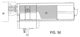
図5a〜5fに制御シーケンスによる種々の動作段階におけるスクラップ剪断機の状態を示す。図5aでは、供給チャンネル30内に破線で示したように長尺の金属スクラップ35が搬入されており、これが作業員によって確認されると、統括制御装置70にスタート指令が送られる。
Figures 5a to 5f show the state of the scrap shears at various stages of operation according to the control sequence. In FIG. 5 a, a
図5bでは、搬入された金属スクラップ35が統括制御装置70によるフィーダー機40の初期操舵によって直刃剪断機20へ向けて移動され、その先端部が直刃剪断機20の剪断口22に当接したときのフィーダー機40の駆動トルク(負荷トルク)の変化がセンサーにより検出され、この検出結果に基づいて統括制御装置70の制御シーケンスが下向き圧縮工程に切り換えられ、下向き油圧ラム53による下向き圧縮工程が開始される。
In FIG. 5 b, the carried-in
図5cでは、下向き油圧ラム53による下向き圧縮工程が終了し、引き続き側方油圧ラム63による側方圧縮工程が行われる。側方圧縮工程は側方油圧ラム63が予め設定されたストローク端に到達した時点で終了し、その信号が統括制御装置70に与えられると、先ず側方油圧ラム63が、次いで下向き油圧ラム53がそれぞれの初期位置へ復帰移動される。
In FIG. 5 c, the downward compression process by the downward
図5dでは、各油圧ラムの復帰移動が完了し、フィーダー機40による供給工程が開始されている。
In FIG. 5d, the return movement of each hydraulic ram is completed, and the supply process by the
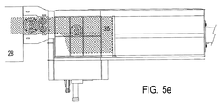
フィーダー機40による金属スクラップの移動量はプッシャーラム41の移動距離を計測してカウントしておき、カウント値が剪断機20の装置諸元に基づいて予め設定された閾値に達したときに、金属スクラップ35の圧縮された先端部が予め設定された短尺スクラップ片の寸法に相当する長さだけカッター刃25,26の位置を超えたことを知る(図5e)。このとき、対応する信号が統括制御装置70に与えられ、それにより剪断機20の油圧スタンパ24が作動されて金属スクラップがカッター刃の直前部でクランプされ、続いて主油圧シリンダ27が駆動されて剪断が実行される(図5f)。
The amount of movement of the metal scrap by the
以降、フィーダー機40による金属スクラップの送り込みと剪断機20による短尺スクラップ片36の切り出しを繰り返し、初回の下向き及び側方各圧縮工程で圧縮された部分の剪断が終了したら再び下向き圧縮工程及び側方圧縮工程から剪断工程を繰り返し、供給チャンネル30内に搬入された金属スクラップ35の全長分についてこれを繰り返す。
Thereafter, the feeding of the metal scrap by the
尚、図5a〜5fでは、各一回の下向き圧縮工程及び側方圧縮工程について三回程度の剪断工程が実行されるように示されているが、本発明はこれに限定解釈されるべきではない。 In FIGS. 5a to 5f, it is shown that the shearing process is performed about three times for each one of the downward compression process and the lateral compression process. However, the present invention should not be construed as being limited thereto. Absent.
剪断機から出てくる短尺スクラップ片36は実質的にキューブ形状となっているため、貨物自動車や鉄道貨車で能率的に運搬可能である。従ってこれら短尺スクラップ片をリサイクル処理施設へ搬送すらば、資源物質の効率的な選別と回収が可能である。
Since the
Claims (9)
固定された下部カッター刃と、前記下部カッター刃と協働して前記金属スクラップを剪断する上部カッター刃と、前記金属スクラップを下向きに押さえつけてクランプするための、油圧シリンダ(23)で駆動される油圧スタンパ(24)と、を有するギロチン式の直刃剪断機(20)と、
剪断機(20)の剪断口(22)よりも広い幅を持つ直方体形状の空間を形成する開放型供給チャンネル(30)と、
供給チャンネル(30)内に搬入された金属スクラップ(35)を側方から押し潰して該金属スクラップの幅寸法を減少させる側方油圧ラム(63)と、
供給チャンネル(30)内で幅寸法が減少された金属スクラップ(35)を剪断機(20)の剪断口(22)内へ送り込むフィーダー機(40)とを備えたものにおいて、
前記剪断機(20)が門形の機体フレーム(21)内に形成された通路を有し、前記通路の入口は供給チャンネル(30)の一端面に開口する剪断口(22)を形成し、
側方油圧ラム(63)が剪断口(22)に近接して位置付けられていると共に、供給チャンネル(30)の長手方向の全長よりも短い或る限定された長さ部分のみについて前記金属スクラップの幅寸法を剪断口(22)の内法幅未満に減少させるように適合され、
側方油圧ラム(63)が前記供給チャンネル(30)の内幅と同じ幅寸法を有する下向き油圧ラム(53)と関連づけられ、該下向き油圧ラム(53)は前記供給チャンネル(30)内で剪断口(22)に近接して位置付けられていると共に、供給チャンネル(30)内に搬入された金属スクラップ(35)を側方油圧ラム(63)の作動に先立って下向きに押し潰して前記限定された長さ部分のみについて金属スクラップ(35)の高さ寸法を剪断口(22)の内法高さ未満に減少させるように適合され、
前記下向き油圧ラム(53)は、下向き油圧シリンダ(52)によって前記金属スクラップの高さ方向に直線移動し、前記下向き油圧シリンダの移動方向は、前記直刃剪断機(20)の上部カッター刃を駆動させる主油圧シリンダ(27)の移動方向と前記油圧スタンパ(24)を駆動させる油圧シリンダ(23)の移動方向とに一致し、
前記開放型供給チャンネル(30)の長手方向に、前記主油圧シリンダ(27)、油圧スタンパ(24)の前記油圧シリンダ(23)、及び前記下向き油圧ラム(53)の油圧シリンダ(52)が、この順に配置され、
直刃剪断機(20)、フィーダー機(40)、側方油圧ラム(63)及び下向き油圧ラム(53)の各駆動系が、これらを予め定められた動作順序で作動制御する統括制御装置(70)と関連づけられ、
圧縮された前記金属スクラップの限定された長さ部分が、前記側方油圧ラム(63)及び前記下向き油圧ラム(53)から解放され、かつ、前記金属スクラップが前記フィーダー機(40)により前記剪断口(22)内へ送り込まれた後、前記金属スクラップが前記油圧スタンパにより押さえつけられた状態で、前記直刃剪断機(20)により切断されるように、前記統括制御装置(70)が作動制御することを特徴とするスクラップ剪断機。A scrap shearing machine for shearing a long metal scrap into a plurality of short scrap pieces,
Driven by a fixed lower cutter blade, an upper cutter blade that shears the metal scrap in cooperation with the lower cutter blade, and a hydraulic cylinder (23) for pressing and clamping the metal scrap downward A guillotine-type straight blade shearing machine (20) having a hydraulic stamper (24);
An open-type supply channel (30) that forms a rectangular parallelepiped space having a width wider than the shearing port (22) of the shearing machine (20);
A lateral hydraulic ram (63) that crushes the metal scrap (35) carried into the supply channel (30) from the side to reduce the width dimension of the metal scrap; and
A feeder machine (40) for feeding the metal scrap (35) whose width dimension is reduced in the supply channel (30) into the shearing port (22) of the shearing machine (20),
The shearing machine (20) has a passage formed in a portal-shaped body frame (21), and the entrance of the passage forms a shearing opening (22) that opens to one end face of the supply channel (30),
A lateral hydraulic ram (63) is positioned proximate to the shear port (22) and only a limited length of the length of the supply channel (30) in the longitudinal direction of the metal scrap is limited to a certain length. Adapted to reduce the width dimension to less than the internal width of the shear opening (22),
A lateral hydraulic ram (63) is associated with a downward hydraulic ram (53) having the same width dimension as the inner width of the supply channel (30), and the downward hydraulic ram (53) is sheared within the supply channel (30). The metal scrap (35) carried in the supply channel (30) is squeezed downward prior to the operation of the side hydraulic ram (63) and positioned in the vicinity of the mouth (22). Adapted to reduce the height dimension of the metal scrap (35) only below the inner height of the shear opening (22),
The downward hydraulic ram (53) is linearly moved in the height direction of the scrap metal by the downward hydraulic cylinder (52), and the downward hydraulic cylinder moves in the direction of the upper cutter blade of the straight blade shearing machine (20). Coincides with the moving direction of the main hydraulic cylinder (27) to be driven and the moving direction of the hydraulic cylinder (23) to drive the hydraulic stamper (24),
In the longitudinal direction of the open supply channel (30), the main hydraulic cylinder (27), the hydraulic cylinder (23) of the hydraulic stamper (24), and the hydraulic cylinder (52) of the downward hydraulic ram (53), Arranged in this order,
General control device that controls the operation of each drive system of the straight blade shearing machine (20), feeder machine (40), side hydraulic ram (63) and downward hydraulic ram (53) in a predetermined operation sequence ( 70)
A limited length portion of the compressed metal scrap is released from the lateral hydraulic ram (63) and the downward hydraulic ram (53), and the metal scrap is sheared by the feeder machine (40). After being fed into the mouth (22), the overall control device (70) is controlled so that the metal scrap is cut by the straight blade shearing machine (20) while being pressed by the hydraulic stamper. A scrap shearing machine characterized by
a)下向き油圧ラム(53)を駆動して前記限定された長さ部分のみについて金属スクラップの高さ寸法を剪断口(22)の内法高さ未満に減少させる下向き圧縮工程、
b)側方油圧ラム(63)を駆動して前記限定された長さ部分のみについて金属スクラップの幅寸法を剪断口(22)の内法幅未満に減少させる側方圧縮工程、
c)フィーダー機(40)を駆動して供給チャンネル(30)内の金属スクラップを直刃剪断機(20)へ向けて送り込む供給工程、及び
e)直刃剪断機(20)を駆動して、その剪断口(22)に送り込まれた金属スクラップの先端部から短尺スクラップ片(36)を切り出す剪断工程、
を順に繰り返す制御シーケンスを有することを特徴とする請求項1に記載のスクラップ剪断機。The overall control device (70) includes a sequence controller, and the sequence controller
a) a downward compression step of driving a downward hydraulic ram (53) to reduce the height dimension of the metal scrap below the internal height of the shear port (22) for only the limited length portion;
b) a lateral compression step in which the lateral hydraulic ram (63) is driven to reduce the width dimension of the metal scrap below the internal width of the shear port (22) only for the limited length portion;
c) a feeding process in which the feeder machine (40) is driven to feed the metal scrap in the supply channel (30) toward the straight blade shearing machine (20); and e) the straight blade shearing machine (20) is driven, A shearing step of cutting a short scrap piece (36) from the tip of the metal scrap fed to the shearing port (22),
The scrap shearing machine according to claim 1, wherein the scrap shearing machine has a control sequence that repeats the steps in order.
Applications Claiming Priority (3)
| Application Number | Priority Date | Filing Date | Title |
|---|---|---|---|
| JP2007180936 | 2007-07-10 | ||
| JP2007180936 | 2007-07-10 | ||
| PCT/JP2008/062516 WO2009008483A1 (en) | 2007-07-10 | 2008-07-10 | Scrap shearing machine |
Related Child Applications (1)
| Application Number | Title | Priority Date | Filing Date |
|---|---|---|---|
| JP2009236133A Division JP5317285B2 (en) | 2007-07-10 | 2009-10-13 | Scrap shearing method |
Publications (2)
| Publication Number | Publication Date |
|---|---|
| JP4484961B2 true JP4484961B2 (en) | 2010-06-16 |
| JPWO2009008483A1 JPWO2009008483A1 (en) | 2010-09-09 |
Family
ID=40228654
Family Applications (2)
| Application Number | Title | Priority Date | Filing Date |
|---|---|---|---|
| JP2009522674A Active JP4484961B2 (en) | 2007-07-10 | 2008-07-10 | Scrap shearing machine |
| JP2009236133A Active JP5317285B2 (en) | 2007-07-10 | 2009-10-13 | Scrap shearing method |
Family Applications After (1)
| Application Number | Title | Priority Date | Filing Date |
|---|---|---|---|
| JP2009236133A Active JP5317285B2 (en) | 2007-07-10 | 2009-10-13 | Scrap shearing method |
Country Status (7)
| Country | Link |
|---|---|
| US (1) | US8210457B2 (en) |
| EP (1) | EP2177270B1 (en) |
| JP (2) | JP4484961B2 (en) |
| KR (1) | KR101148680B1 (en) |
| CN (1) | CN101801533B (en) |
| TW (1) | TWI444238B (en) |
| WO (1) | WO2009008483A1 (en) |
Cited By (1)
| Publication number | Priority date | Publication date | Assignee | Title |
|---|---|---|---|---|
| JP2010046795A (en) * | 2007-07-10 | 2010-03-04 | Towani:Kk | Scrap shearing method |
Families Citing this family (22)
| Publication number | Priority date | Publication date | Assignee | Title |
|---|---|---|---|---|
| DE102011086693A1 (en) | 2011-05-05 | 2012-11-08 | Herbold Meckesheim Gmbh | Device for crushing feedstock |
| JP5843097B2 (en) * | 2011-09-15 | 2016-01-13 | 株式会社とわに | Crushing pre-processing cutting machine |
| WO2014069035A1 (en) | 2012-11-05 | 2014-05-08 | 株式会社とわに | Aeroplane demolition method |
| CN103692235B (en) * | 2013-12-06 | 2015-10-21 | 常州金安冶金设备有限公司 | A kind of scrap cutter cutterhead fabricating tools |
| JP6310268B2 (en) * | 2014-02-10 | 2018-04-11 | 株式会社とわに | Scrap processing equipment for aircraft |
| CN105409608B (en) * | 2015-11-27 | 2019-01-01 | 安徽清保竹业有限公司 | A kind of moso bamboo truncation control system |
| CN105538773B (en) * | 2016-01-18 | 2017-07-07 | 博海威玛(烟台)机械有限公司 | A kind of extruder with self-adapting locking mechanism |
| BE1023797B1 (en) * | 2016-01-22 | 2017-07-27 | Presses Et Cisailles Lefort, Société Anonyme | Method of working for the processing of scrap at a scrap yard and shear press or press or shear used for this method |
| JP5952513B1 (en) * | 2016-03-14 | 2016-07-13 | 可明 高倉 | Press device and method for pressing small metal scrap using the press device |
| CN107414174B (en) * | 2017-07-27 | 2023-04-25 | 福安市中虹机电技术开发有限公司 | Waste treatment device of silicon steel sheet shearing machine |
| US10898902B2 (en) * | 2017-12-20 | 2021-01-26 | Taiyuan University Of Science And Technology | Production line for recycling and processing waste materials of steel rolling |
| CN108687392A (en) * | 2018-06-07 | 2018-10-23 | 江阴市圣博液压机械有限公司 | It is a kind of to automate the cutter that gives up again |
| WO2020074931A1 (en) * | 2018-10-12 | 2020-04-16 | Stamatis Gizelis S.A. | Electromechanical shears for vertical cutting |
| CN110064795B (en) * | 2019-05-22 | 2020-05-05 | 太原科技大学 | Waste production system for steelmaking |
| CN110293437A (en) * | 2019-07-23 | 2019-10-01 | 深圳市楚旺自动化有限公司 | A kind of lathe Solid state fermentation machine |
| CN112170922B (en) * | 2020-09-30 | 2021-11-26 | 安徽金贺财建筑工程有限公司 | Cutting device waste recovery mechanism for panel |
| CN112570784A (en) * | 2020-12-09 | 2021-03-30 | 唐山长城门业有限公司 | Low-consumption plate shearing machine for fireproof door |
| KR20220120940A (en) | 2021-02-24 | 2022-08-31 | 주식회사 태일 | Boom Assembly for Multi stage Cylinder for Metel Cutting Machine |
| WO2022204804A1 (en) * | 2021-03-29 | 2022-10-06 | Ats Automation Tooling Systems Inc. | Tube cutter assembly and cutting method |
| CN113426539A (en) * | 2021-07-05 | 2021-09-24 | 郑州竹林活性炭开发有限公司 | Crushing device for preparing activated carbon from coconut shells |
| CN114251318B (en) * | 2021-12-21 | 2023-12-19 | 江苏高德液压机械有限公司 | Quick box-type shearing machine and working method thereof |
| CN114289167A (en) * | 2022-01-20 | 2022-04-08 | 云南凯瑞特重工科技有限公司 | Inclined type caterpillar band moving shearing machine |
Citations (6)
| Publication number | Priority date | Publication date | Assignee | Title |
|---|---|---|---|---|
| JPS4919304B1 (en) * | 1970-04-11 | 1974-05-16 | ||
| JPS514684A (en) * | 1974-05-13 | 1976-01-14 | Lindemann Maschfab Gmbh | |
| JPH0224016A (en) * | 1988-07-11 | 1990-01-26 | Fuji Car Mfg Co Ltd | Cutting device for scrap |
| JPH0390318U (en) * | 1989-12-25 | 1991-09-13 | ||
| JPH03120319U (en) * | 1990-03-22 | 1991-12-11 | ||
| JPH0584597A (en) * | 1991-09-27 | 1993-04-06 | Goshina Sangyo Kk | Press-shear for scrap |
Family Cites Families (13)
| Publication number | Priority date | Publication date | Assignee | Title |
|---|---|---|---|---|
| US3101045A (en) * | 1959-12-31 | 1963-08-20 | Waldemar Lindemann | Charging box for a machine for operating on metal or similar scrap |
| JPS4922740B1 (en) * | 1970-11-19 | 1974-06-11 | ||
| US3994326A (en) * | 1975-08-19 | 1976-11-30 | Sarten Chester A | Grooving machine |
| US4188876A (en) * | 1976-01-14 | 1980-02-19 | Graves Donald J | Junk metal compressor |
| DE2727436C2 (en) * | 1977-06-18 | 1984-03-22 | Lindemann Maschinenfabrik GmbH, 4000 Düsseldorf | SCRAP SHEARS |
| IT1096114B (en) * | 1978-04-12 | 1985-08-17 | Vezzani Spa Off | PROCESS AND MACHINE FOR COMPRESSING AND CUTTING METAL SCRAP |
| DE3134021A1 (en) * | 1981-08-28 | 1983-03-10 | Lindemann Maschinenfabrik GmbH, 4000 Düsseldorf | Scrap shears |
| DE3439002A1 (en) * | 1984-10-25 | 1986-04-30 | Lindemann Maschinenfabrik GmbH, 4000 Düsseldorf | SCRAP SHEARS |
| US4881459A (en) * | 1988-03-17 | 1989-11-21 | Allied Gator, Inc. | Hydraulic scrap shear |
| US6352012B1 (en) * | 1997-09-30 | 2002-03-05 | John J. Borzym | Supported shear with reversible linear drive and in-feed table therefor |
| DE19804789B4 (en) * | 1998-02-06 | 2004-04-08 | Metso Lindemann Gmbh | Process for the production of compacts by means of a shear packet press and a shear packet press for carrying out the method |
| CN1221376C (en) * | 2004-01-13 | 2005-10-05 | 江阴市华宏液压机械研究所 | Waste metal hydraulic pressure baling shearing machine |
| EP2177270B1 (en) * | 2007-07-10 | 2019-01-02 | Nihon Sougou Recycle Co., Ltd. | Scrap shearing machine |
-
2008
- 2008-07-10 EP EP08791064.2A patent/EP2177270B1/en not_active Not-in-force
- 2008-07-10 KR KR1020107000292A patent/KR101148680B1/en active IP Right Grant
- 2008-07-10 US US12/668,124 patent/US8210457B2/en active Active
- 2008-07-10 CN CN2008801062188A patent/CN101801533B/en active Active
- 2008-07-10 WO PCT/JP2008/062516 patent/WO2009008483A1/en active Application Filing
- 2008-07-10 JP JP2009522674A patent/JP4484961B2/en active Active
-
2009
- 2009-01-07 TW TW098100357A patent/TWI444238B/en active
- 2009-10-13 JP JP2009236133A patent/JP5317285B2/en active Active
Patent Citations (6)
| Publication number | Priority date | Publication date | Assignee | Title |
|---|---|---|---|---|
| JPS4919304B1 (en) * | 1970-04-11 | 1974-05-16 | ||
| JPS514684A (en) * | 1974-05-13 | 1976-01-14 | Lindemann Maschfab Gmbh | |
| JPH0224016A (en) * | 1988-07-11 | 1990-01-26 | Fuji Car Mfg Co Ltd | Cutting device for scrap |
| JPH0390318U (en) * | 1989-12-25 | 1991-09-13 | ||
| JPH03120319U (en) * | 1990-03-22 | 1991-12-11 | ||
| JPH0584597A (en) * | 1991-09-27 | 1993-04-06 | Goshina Sangyo Kk | Press-shear for scrap |
Cited By (1)
| Publication number | Priority date | Publication date | Assignee | Title |
|---|---|---|---|---|
| JP2010046795A (en) * | 2007-07-10 | 2010-03-04 | Towani:Kk | Scrap shearing method |
Also Published As
| Publication number | Publication date |
|---|---|
| KR101148680B1 (en) | 2012-05-21 |
| TW201002455A (en) | 2010-01-16 |
| EP2177270A4 (en) | 2015-04-08 |
| US8210457B2 (en) | 2012-07-03 |
| CN101801533B (en) | 2012-05-30 |
| JPWO2009008483A1 (en) | 2010-09-09 |
| CN101801533A (en) | 2010-08-11 |
| EP2177270A1 (en) | 2010-04-21 |
| JP5317285B2 (en) | 2013-10-16 |
| KR20100038359A (en) | 2010-04-14 |
| WO2009008483A1 (en) | 2009-01-15 |
| US20110000991A1 (en) | 2011-01-06 |
| EP2177270B1 (en) | 2019-01-02 |
| TWI444238B (en) | 2014-07-11 |
| JP2010046795A (en) | 2010-03-04 |
Similar Documents
| Publication | Publication Date | Title |
|---|---|---|
| JP4484961B2 (en) | Scrap shearing machine | |
| US3141401A (en) | Machine for preparing scrap metal | |
| US3039343A (en) | Double cutting metal shears | |
| US3129656A (en) | Multiple compression baling press and shear | |
| US4213385A (en) | Scrap shearing machine | |
| JP2014161878A (en) | Scrap discharger of press die | |
| KR20170064659A (en) | Forming appartus for joint stopper of wire | |
| US5551325A (en) | Tire cutting machine | |
| JP5362299B2 (en) | Scrap shearing machine | |
| CN203221102U (en) | Trimming waste cutting-off die assembly | |
| JP5843097B2 (en) | Crushing pre-processing cutting machine | |
| JP5952513B1 (en) | Press device and method for pressing small metal scrap using the press device | |
| JP6770298B2 (en) | Crushing cutting device for vehicles | |
| US3049274A (en) | Metal severing device | |
| JP6767053B2 (en) | Rebar cutting device | |
| JP6228587B2 (en) | Steel band coil binding band processing equipment | |
| EP1449608B1 (en) | Machine for separating blocks of iron material from a mass of loose scrap | |
| CN107639279A (en) | A kind of shear lathe for facilitating automatic loading/unloading | |
| CN210080844U (en) | Double-blade shearing machine for treating automobile waste shells | |
| CN216801863U (en) | Block cutter | |
| JP3558030B2 (en) | Device for removing press debris and method of operating the same | |
| CN218535761U (en) | Automatic feeding structure for friction press | |
| CN211304950U (en) | Horizontal shearing machine | |
| KR101992814B1 (en) | recovery device for cutting chip | |
| KR20220170091A (en) | Waste automobile cutting device |
Legal Events
| Date | Code | Title | Description |
|---|---|---|---|
| TRDD | Decision of grant or rejection written | ||
| A01 | Written decision to grant a patent or to grant a registration (utility model) |
Free format text: JAPANESE INTERMEDIATE CODE: A01 Effective date: 20100317 |
|
| A01 | Written decision to grant a patent or to grant a registration (utility model) |
Free format text: JAPANESE INTERMEDIATE CODE: A01 |
|
| A61 | First payment of annual fees (during grant procedure) |
Free format text: JAPANESE INTERMEDIATE CODE: A61 Effective date: 20100323 |
|
| R150 | Certificate of patent or registration of utility model |
Ref document number: 4484961 Country of ref document: JP Free format text: JAPANESE INTERMEDIATE CODE: R150 Free format text: JAPANESE INTERMEDIATE CODE: R150 |
|
| FPAY | Renewal fee payment (event date is renewal date of database) |
Free format text: PAYMENT UNTIL: 20130402 Year of fee payment: 3 |
|
| FPAY | Renewal fee payment (event date is renewal date of database) |
Free format text: PAYMENT UNTIL: 20130402 Year of fee payment: 3 |
|
| FPAY | Renewal fee payment (event date is renewal date of database) |
Free format text: PAYMENT UNTIL: 20140402 Year of fee payment: 4 |
|
| R250 | Receipt of annual fees |
Free format text: JAPANESE INTERMEDIATE CODE: R250 |
|
| R250 | Receipt of annual fees |
Free format text: JAPANESE INTERMEDIATE CODE: R250 |
|
| R250 | Receipt of annual fees |
Free format text: JAPANESE INTERMEDIATE CODE: R250 |
|
| R250 | Receipt of annual fees |
Free format text: JAPANESE INTERMEDIATE CODE: R250 |
|
| R250 | Receipt of annual fees |
Free format text: JAPANESE INTERMEDIATE CODE: R250 |
|
| R250 | Receipt of annual fees |
Free format text: JAPANESE INTERMEDIATE CODE: R250 |
|
| R250 | Receipt of annual fees |
Free format text: JAPANESE INTERMEDIATE CODE: R250 |
|
| R250 | Receipt of annual fees |
Free format text: JAPANESE INTERMEDIATE CODE: R250 |
|
| R250 | Receipt of annual fees |
Free format text: JAPANESE INTERMEDIATE CODE: R250 |
|
| R250 | Receipt of annual fees |
Free format text: JAPANESE INTERMEDIATE CODE: R250 |
|
| R250 | Receipt of annual fees |
Free format text: JAPANESE INTERMEDIATE CODE: R250 |