JP4482358B2 - Sequin feeder - Google Patents
Sequin feeder Download PDFInfo
- Publication number
- JP4482358B2 JP4482358B2 JP2004082867A JP2004082867A JP4482358B2 JP 4482358 B2 JP4482358 B2 JP 4482358B2 JP 2004082867 A JP2004082867 A JP 2004082867A JP 2004082867 A JP2004082867 A JP 2004082867A JP 4482358 B2 JP4482358 B2 JP 4482358B2
- Authority
- JP
- Japan
- Prior art keywords
- sequin
- tape
- cutting
- sewing machine
- delivery member
- Prior art date
- Legal status (The legal status is an assumption and is not a legal conclusion. Google has not performed a legal analysis and makes no representation as to the accuracy of the status listed.)
- Expired - Fee Related
Links
Images


Description
本発明は、シークインをミシンの縫付位置に供給するシークイン供給装置に関するものである。 The present invention relates to a sequin supply device that supplies sequin to a sewing position of a sewing machine.
従来、刺繍ミシンを用いてシークイン(スパンコールともいう)を加工布に縫い付ける技術が知られている。例えば、特許文献1には、シークインの縫付途中に、ジャンプソレノイドで針棒叩きを針棒から退避させ、天秤で上糸を引き締めて、布送りに伴うシークインの裏返りを防止する技術が記載されている。特許文献2には、シークイン縫いに必要な縫製データを刺繍ミシンのコントローラにて設定する技術が記載されている。
Conventionally, a technique for sewing sequins (also called sequins) to a work cloth using an embroidery sewing machine is known. For example,
また、従来、シークインを連ねたテープを送り出し、テープから先頭のシークインを切断してミシンの縫付位置に供給する装置が知られている。例えば、特許文献3には、テープを幅方向にずれないように案内するガイドレールを備えた装置が記載されている。特許文献4には、シークインのサイズ変更に対応できるように、左右のガイドレールの間隔をテープの幅に応じて調整する手段を備えた装置が記載されている。
ところで、シークインのサイズが変わると、テープの幅のみならず、テープの送り出し量が変化し、これに伴い、シークインの切断位置も変化する。このため、従来は、シークインのサイズに合わせて、供給装置の該当部材を調整した後、コントローラ上のボタンを押して、テープ送りモータを動作させ、テープを試しに送り出して、先頭のシークインの形状を検査し、正規形状のシークインが得られるまで、調整、送り出し、検査等の作業を繰り返し行っていた。 By the way, when the sequin size changes, not only the tape width but also the tape feed amount changes, and the sequin cutting position also changes accordingly. For this reason, conventionally, after adjusting the corresponding member of the supply device according to the size of the sequin, press the button on the controller to operate the tape feed motor, send out the tape for trial, and change the shape of the first sequin. Inspection, adjustment, delivery, and inspection work were repeated until a regular shape sequin was obtained.
ところが、多頭式ミシンにおいては、機枠が複数台のミシンを並設するために横長になっているにも拘わらず、コントローラは機枠の片端に1台設置されているだけなので、調整作業に際し、従来は、作業者が各ミシンとコントローラとの間を何度も行き来する必要があった。しかも、供給装置が各ミシンに付設されているため、例えば20頭立てのミシンで全供給装置の調整作業を完了するには、多大な手間と時間がかかるという問題点があった。 However, in a multi-head type sewing machine, the controller is only installed at one end of the machine frame, even though the machine frame is horizontally long because a plurality of sewing machines are arranged side by side. Conventionally, an operator has to go back and forth between each sewing machine and the controller many times. In addition, since the supply device is attached to each sewing machine, for example, it takes a lot of time and effort to complete the adjustment work of all the supply devices with a 20-head sewing machine.
また、従来は、テープ17の送り出し量をモータの回転数を変えることで調整しているので、モータと送出部材との間にある可動部の組付誤差や慣性等の不定要因により、送出部材の前進端位置を正確に決めることが困難であった。このため、テープ17の切断位置が不正確になりやすく、特に、直径5mm程度の小さなシークインSの場合に、切断不良が目立ち、縫製品の品質が低下するという問題点があった。
Further, conventionally, the feeding amount of the
さらに、シークインを連ねたテープは、図10に示すように、シークイン同士の接続部が幅狭となっているため、送り出す途中でばたついたり後戻りしたりしやすい。従来のシークイン供給装置は、テープ17をガイドレールで直進させることはできるが、テープ17の厚さ方向の挙動を抑えることが困難であった。このため、やはりテープ17の切断位置が不正確になりやすく、装飾部品であるシークインSがいびつな形状で切断されて加工布に縫い付けられる不具合があった。
Further, as shown in FIG. 10, the tape with the sequins connected is easy to flutter and return during the feeding because the connecting portion between the sequins is narrow. Although the conventional sequin supply device can move the
本発明の目的は、上記課題を解決し、テープの厚さ方向の挙動を抑え、シークインの接続部を切断部材に正確に位置決めできるシークイン供給装置を提供することにある。 The objective of this invention is providing the sequin supply apparatus which can position the connection part of a sequin accurately to a cutting member, solving the said subject, suppressing the behavior of the thickness direction of a tape.
また、本発明の別の目的は、シークインのサイズ変更に際し、送出部材の前進端位置を正確に決め、シークインの切断不良を確実に防止できるシークイン供給装置を提供することにある。 Another object of the present invention is to provide a sequin supply device that can accurately determine the forward end position of the delivery member and reliably prevent sequin cutting failure when the sequin size is changed.
上記の課題を解決するために、本発明は、シークインを連ねたテープをミシンの縫付位置に向けて案内する案内部材と、案内部材に沿わせてテープを送り出す送出部材と、送出部材を駆動するアクチュエータと、テープから先頭のシークインを切断する切断部材と、該切断時に切断部材の近くでテープを案内部材に押し付ける押付手段とを備え、送出部材がシークインの穴(h)に係合する係合部(33)を備え、押付手段が送出部材の前進端位置で係合部を案内部材に向けて押し動かすカム部を含むものである。 In order to solve the above problems, the present invention drives a guide member that guides a tape with sequins toward a sewing position of the sewing machine, a delivery member that feeds the tape along the guide member, and a delivery member. And an actuator for cutting the leading sequin from the tape , and a pressing means for pressing the tape against the guide member near the cutting member at the time of cutting, and the engaging member engages with the hole (h) of the sequin. It includes a joint portion (33), and the pressing means includes a cam portion that moves the engaging portion toward the guide member at the forward end position of the delivery member .
シークイン供給装置は、先頭のシークインの切断位置を調整する調整部材を備え、調整部材に送出部材の前進端位置を規制する規制部と、規制部をテープの送り出し方向に位置調整する調整部とを設けることが好ましい。
また、係合部を係合させるシークインの穴のテープ先頭からの順位をシークインのサイズ変更に伴って変更するときの送出部材の後退端位置を調整する部材を設けることがより好ましい。 Sequin feeding device comprises an adjustment member for adjusting the cutting position of the leading sequin, a regulating portion for regulating the forward end position of the delivery member to the adjusting member, the adjusting section for positioning the regulating portion in the feeding direction of the tape Is preferably provided .
It is more preferable to provide a member that adjusts the position of the retracting end of the delivery member when the order of the sequin hole from which the engaging portion is engaged is changed with the sequin size change .
上記各手段において、ミシンの種類は、特に限定されず、例えば、刺繍ミシン、直線縫いミシン、環縫いミシン等、シークインを縫付可能な各種ミシンを使用できる。シークインの形状は、特に限定されず、真円形、楕円形、角丸四角形、星形、菱形等を例示できる。シークインを連ねたテープとは、シークインが数珠繋ぎになった帯状材であり、その供給源にはリール、ボビン、容器等を使用できる。 In each of the above means, the kind of the sewing machine is not particularly limited, and various sewing machines capable of sewing sequins such as an embroidery sewing machine, a straight stitch sewing machine, and a chain stitch sewing machine can be used. The shape of sequin is not particularly limited, and examples thereof include a perfect circle, an ellipse, a rounded quadrangle, a star, and a rhombus. The tape in which sequins are connected is a strip-like material in which sequins are connected in a daisy chain, and a reel, bobbin, container, or the like can be used as a supply source.
テープの案内部材としては、例えば、テープを直進案内するガイド溝を備えた部材を使用できる。また、シークインのサイズ変更に対応できるように、一対の案内板を間隔調整可能に設けるのが好ましい。さらに、ガイド溝の中心を変えずに一対の案内板の間隔を調整できるように、両方の案内板を連動部材により平行移動可能に連結するとよい。 As the tape guide member, for example, a member having a guide groove for guiding the tape straight can be used. In addition, it is preferable to provide a pair of guide plates so that the distance between the guide plates can be adjusted so that the sequin size can be changed. Further, both guide plates may be connected by an interlocking member so as to be movable in parallel so that the distance between the pair of guide plates can be adjusted without changing the center of the guide groove.
テープの送出部材としては、回転部材、揺動部材、直線移動部材、直線移動と揺動を組み合わせた複合運動部材等を例示できる。送出部材を駆動するアクチュエータには、例えば、モータ、ソレノイド、エアシリンダ等を使用できる。モータとしては、テープの送り出し量を容易に制御できる点で、ステッピングモータが好ましい。 Examples of the tape feeding member include a rotating member, a swinging member, a linear moving member, a combined motion member combining linear movement and swinging, and the like. For example, a motor, a solenoid, an air cylinder, or the like can be used as the actuator that drives the delivery member. As the motor, a stepping motor is preferable in that the amount of tape fed can be easily controlled.
切断部材は、先頭のシークインと次のシークインとの接続部を切断する部材であり、具体的には、接続部を剪断して先頭のシークインをテープから切り取るカッタ、あるいは、先頭のシークインを引っ張ってテープから切り離す部材等を使用できる。また、切断部材を専用のアクチュエータで駆動してもよく、ミシン可動部を利用して駆動してもよい。 The cutting member is a member that cuts the connecting portion between the first sequin and the next sequin. Specifically, the cutting member shears the connecting portion to cut the first sequin from the tape, or pulls the first sequin. A member to be separated from the tape can be used. Further, the cutting member may be driven by a dedicated actuator, or may be driven using a sewing machine movable portion.
押付手段としては、ソレノイドやエアシリンダ等のアクチュエータも使用可能であるが、簡単かつ小型に構成できる点で、カムを用いるのが好ましい。具体的には、送出部材にシークインの穴に係合する係合部を設け、押付手段に送出部材の前進端位置で係合部を案内部材に向けて押し動かすカム部を設けるとよい。係合部にはピンやロッド等の細長部材を例示でき、カム部には傾斜面や傾斜溝等の斜状カムを例示できる。 An actuator such as a solenoid or an air cylinder can be used as the pressing means, but a cam is preferably used because it can be configured simply and compactly. Specifically, an engaging portion that engages with a sequin hole is provided on the sending member, and a cam portion that pushes the engaging portion toward the guide member at the forward end position of the sending member may be provided on the pressing means. The engaging portion can be an elongated member such as a pin or a rod, and the cam portion can be an oblique cam such as an inclined surface or an inclined groove.
調整部材としては、切断部材の位置を調整する部材を用いてもよく、テープの送り出し量を調整する部材を用いてもよい。ただし、前者の場合は、ミシンの振動等で送出部材の移動量が変化すると、切断位置がずれ、シークインを正規形状(例えば真円形)に切断できなくなる可能性がある。これに対し、後者の場合は、送出部材の移動量を調整することで、シークインの接続部を切断部材に正確に位置決めし、装飾部品としてのシークインを見栄えよく切断できる利点がある。具体的には、調整部材に、送出部材の前進端位置を規制する規制部と、規制部をテープの送り出し方向に位置調整する調整部とを設けるのが好ましい。 As the adjusting member, a member that adjusts the position of the cutting member may be used, or a member that adjusts the tape feed amount may be used. However, in the former case, if the amount of movement of the delivery member changes due to the vibration of the sewing machine or the like, the cutting position may be shifted, and the sequin may not be cut into a regular shape (for example, a perfect circle). On the other hand, in the latter case, there is an advantage that the connecting part of the sequin can be accurately positioned on the cutting member by adjusting the moving amount of the delivery member, and the sequin as the decorative part can be cut with good appearance. Specifically, it is preferable to provide the adjusting member with a restricting portion for restricting the forward end position of the delivery member and an adjusting portion for adjusting the position of the restricting portion in the tape feeding direction.
特に、調整部材の規制部をテープの送り出し方向に位置調整することで、シークインのサイズ変更に際して、送出部材の前進端位置を正確に決めることができる。また、押付手段にカムを用いる場合は、カムを調整部材又は送出部材の一部に設けることで、供給装置を小型かつ簡単に構成することができる。具体的には、送出部材にシークインの穴に係合する係合部を設け、押付手段に送出部材の前進端位置で係合部を案内部材に向けて押し動かすカム部を設け、カム部を送出部材と規制部のどちらか一方又は両方に形成するとよい。 In particular, by adjusting the position of the regulating portion of the adjusting member in the tape feeding direction, the forward end position of the feeding member can be accurately determined when the sequin size is changed. When a cam is used as the pressing means, the supply device can be configured in a small and simple manner by providing the cam on a part of the adjustment member or the delivery member. Specifically, an engaging portion that engages with the sequin hole is provided on the delivery member, and a cam portion that pushes the engaging portion toward the guide member at the forward end position of the delivery member is provided on the pressing means. It is good to form in either one or both of a delivery member and a control part.
請求項1,2,3に係る発明のシークイン供給装置によれば、シークインの切断時にテープを案内部材に押し付けるので、テープの厚さ方向の挙動を抑えて、シークインの接続部を切断部材に正確に位置決めすることができる。
請求項2,3に係る発明のシークイン供給装置によれば、調整部材に送出部材の前進端位置を規制する規制部と、規制部を位置調整する調整部とを設けたので、シークインのサイズ変更に際し、送出部材の前進端位置を正確に決めて、シークインの切断不良を確実に防止することができる。
請求項3に係る発明のシークイン供給装置によれば、送出部材の係合部を係合させるシークインの穴のテープ先頭からの順位をシークインのサイズ変更に伴って変更するときの送出部材の後退端位置を調整する部材を設けたので、シークインのサイズ変更に対応できる。
According to the sequin supply device of the inventions according to
According to the sequin supply device of the inventions according to
According to the sequin supply device of the invention according to
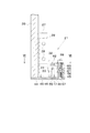
図7に本発明を実施するための最良の形態を示す。このシークイン供給装置は、シークインSを連ねたテープ17をミシンの縫付位置に向けて案内するガイド溝46を有する案内部材44,45(底板、案内板)と、案内部材に沿ってテープを送り出す送出部材31と、送出部材を駆動するアクチュエータとしてのステッピングモータ36(図2参照)と、テープから先頭のシークインを切断する切断部材41と、先頭のシークインの切断位置を調整する調整部材58と、シークインの切断時に切断部材41の近くでテープをガイド溝46の底面に押し付けるカム部としての斜状部64とを備える。
FIG. 7 shows the best mode for carrying out the present invention. This sequin supply device feeds the tape along the
調整部材58には、送出部材31の前進端位置を規制する規制部62と、規制部62をテープの送り出し方向に位置調整する調整部61(調整ボルト:図6参照)とが設けられる。送出部材31には、シークインの穴に係合する係合部としてのL字形の送りピン33が設けられ、調整部材58の規制部62にカム部64が下向きの斜状に形成される。そして、送出部材31の前進端位置で、カム部64が係合部33の下端をガイド溝46の底面に向けて押し下げるように構成される。
The adjusting
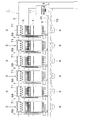
以下、本発明を具体化した実施例を図面に基づいて説明する。図1に示すように、この多頭式ミシン1の機枠2には、複数台(例えば20台)の刺繍ミシン3が並設されている。各刺繍ミシン3はヘッド4とテンション台5とベッド6とを備え、ヘッド4の片側にシークイン供給装置7が付設されている。機枠2にはベッド6と同じ高さにテーブル8が架設され、テーブル8の上に加工布9を保持する刺繍枠10が載置されている。テーブル8の片端には1台のコントローラ11が設置され、コントローラ11により全頭の刺繍ミシン3とシークイン供給装置7とが同期制御される。
Embodiments of the present invention will be described below with reference to the drawings. As shown in FIG. 1, a plurality of (for example, 20)
図2,図3に示すように、シークイン供給装置7は、ヘッド4に取り付けられるフレーム13を備えている。フレーム13には、スライドカバー14がエアシリンダ15によりリニアガイド16を介して斜めに昇降可能に支持されている。スライドカバー14には、シークインSを直列に連ねたテープ17(詳細は図7参照)を収納するリール18と、テープ17を案内する複数の回転子19と、テープ17を刺繍ミシン3の縫付位置(針棒20の下側)に供給する供給機構21とが設けられている。
As shown in FIGS. 2 and 3, the
供給機構21は、エアシリンダ15の伸長時に、加工布9に接近する稼働位置に配置され(図3a参照)、エアシリンダ15の収縮時に、加工布9から上方へ離れた休止位置に配置される(図3b参照)。スライドカバー14には突起22が設けられ、フレーム13に係止板23とこれを回動するソレノイド24とが設けられている。そして、コントローラ11にてシークイン縫いを行わない刺繍ミシン3が指定され、そのミシン3に該当するシークイン供給装置7のソレノイド24が励磁され、係止板23に突起22が係止され、供給機構21が休止位置に保持される。
The
図4に示すように、供給機構21の基板26にはブロック27によりロッド28が保持され、ロッド28にスライダ29が前後動可能に支持されている。スライダ29には送出部材31がボルト30で上下に揺動可能に軸支され、バネ32によって下方へ付勢されている。送出部材31の前端にはL字形の送りピン33が下向きに突設され、その下端後側に斜面34が形成されている。スライダ29の前進時には、送出部材31が送りピン33の下端をシークインSの穴hに挿入して、テープ17を刺繍ミシン3の縫付位置に向けて送り出す。スライダ29の後退時には、送出部材31が斜面34の作用で上方へ揺動し、送りピン33がテープ17から離脱する。
As shown in FIG. 4, a
基板26の裏面(送出部材31と反対側の面)にはステッピングモータ36が設置され、その出力軸37はアーム38、リンク39を介しスライダ29に連結されている。縫製運転中は、ステッピングモータ36が刺繍ミシン3の主軸(図示略)と同期して制御され、出力軸37の正逆回転に伴いスライダ29が前後に駆動され、送出部材31の前進時に、テープ17の先頭シークインSが針棒20の下側に供給される。基板26の前端には切断部材41が軸40で上下に回動可能に支持されている。そして、針棒20の下降時に、針止め42(図2参照)が切断部材41を踏み下げ、切断部材41が先頭シークインSをテープ17から切断する。切断部材41には、左右方向(テープ送り方向と直角の方向)に長いカッタが用いられている。
A stepping
図5,図6に示すように、供給機構21の底板44上には左右一対の案内板45が載置され、各案内板45の相対面にテープ17を縫付位置に向けて直進案内するガイド溝46が形成されている。底板44は案内板45と共に案内部材を構成し、底板44によりガイド溝46の底面が形成されている。右側の案内板45は長孔47を通るネジ48で底板44に対し左右方向へ位置調整可能に取り付けられている。左側の案内板45は前後2枚の幅板49で右側の案内板45に対し平行移動可能に保持されている。前側の幅板49には連動板51がボルト50で軸支され、連動板51の切欠52に案内板45のピン53が嵌入されている。そして、図6(a)(b)に示すように、連動板51を回動することにより、ガイド溝46の間隔がその中心を変えずにテープ17の幅(シークインSの直径)に応じて調整される。
As shown in FIGS. 5 and 6, a pair of left and
左右の案内板45の間において、底板44には送りピン33の下端が嵌入するスリット55が前後に長く形成されている。スリット55の右側において底板44の上には支柱56がネジ57で固定され、支柱56に調整部材58がボルト59で組み付けられている。調整部材58には、支柱56に挿入される長孔60と、支柱56に螺合する調整ボルト61と、送出部材31の前方に突出する規制片62とが設けられている。そして、規制片62は送出部材31の前進端位置を規制する規制部として機能し、調整ボルト61は規制片62を長孔60の長さ範囲でテープ17の送り出し方向(前後方向)に位置調整する調整部として機能する。これにより、調整部材58は、テープ17の送り出し量を加減し、先頭のシークインSの切断位置をその直径に合わせて調整できるように構成されている。
Between the left and
図7に示すように、送出部材31及び規制片62の相対面には斜状部63,64が形成され、斜状部63,64の係合により送出部材31が前進端位置で揺動規制され、刺繍ミシン3の振動等による送りピン33の浮き上がりが防止される。送出部材31側の斜状部63は上向きに形成され、規制片62側の押付手段としてのカム部である斜状部64は下向きに形成されている。そして、送出部材31が前進端位置に達したときに、送出部材31側の斜状部63が規制片62側の斜状部64に係合し、該斜状部64は送出部材31を下方へ揺動し、送りピン33をガイド溝46の底面に向けて押し下げ、送りピン33の下端がテープ17をガイド溝46の底面に押し付けるようになっている。
As shown in FIG. 7,
従って、送りピン33によりテープ17の後退を阻止した状態で、先頭のシークインSと次のシークインSとの接続部を切断位置に正確に位置決めすることができる。また、送りピン33の下端でテープ17を底板44に押し付け、この部分より先のテープ17のばたつきを防止して、シークインSの接続部を切断部材41で正確に切断することもできる。それゆえ、装飾部品であるシークインSの切断不良を確実に防止し、正規形状のシークインSを加工布9に縫い付け、高品質の縫製品を見栄えよく加工することができる。
Accordingly, the connecting portion between the leading sequin S and the next sequin S can be accurately positioned at the cutting position in a state in which the
後側のブロック27にはスライダ29に当接するストップボルト65が螺着され、このボルト65によって送出部材31の後退端位置が調整される。ブロック27の下側には、ガイド溝46の手前でテープ17を底板44に押え伏せる板バネ66と、板バネ66の先端高さを調整するボルト67とが設けられている。
A
そして、すべての各刺繍ミシン3のテンション台5(図1参照)には、各ミシン3と組み合わされたシークイン供給装置7において、ステッピングモータ36を動作させるためのスイッチ69が配置されている。このスイッチ69の位置は各刺繍ミシン3の前に立つ作業者の手が届く範囲内にある。そして、縫製運転の停止中に、作業者がこのスイッチ69を操作したときには、ステッピングモータ36が一回だけ正逆回転し、送出部材31が一往復し、送りピン33がテープ17を送り出す。従って、シークインSのサイズが変わった場合に、作業者はコントローラ11まで行かずともテープ17を即座に送り出すことができる。なお、本実施例のスイッチ69は、縫製運転中に操作されたときに、該当する刺繍ミシン3を一時停止させる機能を兼ね備えている。
Further, on the tension bases 5 (see FIG. 1) of all the
次に、シークインのサイズ変更に伴う調整作業について説明する。図7は、多頭式ミシン1の通常運転時に、供給機構21が例えば直径5mmのシークインSを供給している状態を示す。この場合、送出部材31の送りピン33はテープ17の先頭からの順位が5番目であるシークインSの穴hに係合する。この状態では、ステッピングモータ36が、刺繍ミシン3の主軸と同期して制御され、コントローラ11に設定されたステップ数で回転する。そして、送出部材31が、(a)に示す後退端位置から前進してテープ17を5mm送り出し、(b)に示す前進端位置で規制片62に当接して停止し、先頭のシークインSを底板44の前方へ送り出す。この直後に、針棒20が下降し、針止め42が切断部材41を踏み下げ、切断部材41がテープ17から先頭のシークインSを切り離す。
Next, the adjustment work accompanying the sequin size change will be described. FIG. 7 shows a state in which the
図8は、シークインSの直径が9mmに変わった場合の供給機構21の調整方法を示す。この場合、送出部材31の送りピン33はテープ17の先頭からの順位が3番目であるシークインSの穴hに係合する。このサイズ変更にあたっては、全刺繍ミシン3の停止状態で、まず、コントローラ11において、ステッピングモータ36のステップ数を9mm相当値に設定する。次に、供給機構21において、案内板45を開いてガイド溝46の間隔を調整し、調整部材58を前進させて規制片62の位置を調整する(図6b参照)。続いて、スイッチ69を押し、ステッピングモータ36を動作させ、送出部材31を駆動し、テープ17を試し送りする。そして、切断部材41を指先で押し下げ、先頭のシークインSを切断し、その形状を検査し、不具合があれば、再調整、再送りを繰り返し、正規形状のシークインSを得る。
FIG. 8 shows an adjustment method of the
図9は、シークインSの直径が7mmに変わった場合の供給機構21の調整方法を示す。この場合も、同様の手順で調整作業を進めることができる。ただし、7mmの場合は、送出部材31の送りピン33がテープ17の先頭からの順位が4番目であるシークインSの穴hに係合するときの送出部材31の後退端位置が、前記の5mm,9mmの場合と相違するため、ストップボルト65を回して、スライダ29の原点位置を調整する必要がある。調整後は、スイッチ69を押し、テープ17を送り出し、先頭のシークインSを切断し、形状を検査し、再調整、再送りを繰り返して、正規形状のシークインSを得る。従って、いずれのサイズへの変更に際しても、作業者は各ミシン3の前に立ちながらテープ17の送り出し量を容易に調整することができる。
FIG. 9 shows an adjustment method of the
また、この調整作業にあたっては、調整部材58の規制片62によって送出部材31の前進端位置を規制するので、アーム38、リンク39、送出部材31等の可動部の組付誤差や慣性等による影響を受けることなく、シークインSの接続部を切断部材41に正確に位置決めすることができる。このため、直径5mm程度の小さなシークインSの場合でも、切断不良を確実に防止し、正規形状のシークインを加工布9に縫い付けることができる。なお、規制片62が送出部材31の前進端位置を機械的に規制するので、コントローラ11では、ステッピングモータ36のステップ数を送出部材31が若干オーバーラン気味となる値に設定しておくとよい。
Further, in this adjustment work, the forward end position of the
次に、本実施例では、各刺繍ミシン3において、テンション台5にシークイン供給装置7のエアシリンダ15を動作させるためのスイッチ71が設けられている。このスイッチ71の位置も各刺繍ミシン3の前に立つ作業者の手が届く範囲内にある。従って、縫製運転の停止中に、各ミシンの前でスイッチ71を操作することにより、操作したミシン3に該当する供給機構21を単独で休止位置又は稼働位置に切り替えることができる。
Next, in the present embodiment, each
本発明は前記実施例に限定されるものではなく、例えば以下のように、発明の趣旨から逸脱しない範囲で適宜変更して具体化することもできる。
(1)図1に示すように、テーブル8の下側において、機枠2の両端間にスイッチ棒70を架設する。このスイッチ棒70を、多頭式ミシン1の稼働時に、全刺繍ミシン3を一斉に起動・停止させるためのスイッチとして用い、多頭式ミシン1の休止時には、全シークイン供給装置7のステッピングモータ36を一斉に動作させるためのスイッチとして用いる。こうすれば、シークインサイズの変更に際し、作業者は各ミシン3の前に立ちながら手元でスイッチ棒70を操作できるうえ、全頭の供給装置7で調整を済ませた後に、一回のスイッチ操作でテープ17を一斉に送り出すことができる。
The present invention is not limited to the above-described embodiments. For example, as described below, the present invention can be appropriately modified and embodied without departing from the spirit of the invention.
(1) As shown in FIG. 1, a
(2)各刺繍ミシン3又はその周辺であって各刺繍ミシン3の前に立つ作業者の手が届く範囲内に、各シークイン供給装置7のソレノイド24を動作させるためのスイッチ(図示略)を設け、縫製運転中に、このスイッチが操作されたミシン3に該当する供給機構21を単独で休止位置に保持できるように構成する。
(3)各刺繍ミシン3において、ヘッド4に左右2台のシークイン装置7を設置する。
(2) A switch (not shown) for operating the
(3) In each
(4)図7に示すシークイン供給装置7において、送出部材31と規制片62のどちらか一方に斜状のカム部を設け、他方にローラを支持し、カム部とローラとの当接により送出部材31の前進端位置を規制するように構成する。
(4) In the
3 刺繍ミシン
7 シークイン供給装置
17 テープ
31 送出部材
33 送りピン
36 ステッピングモータ
41 切断部材
44 底板
45 案内板
46 ガイド溝
51 連動板
58 調整部材
61 調整ボルト
62 規制片
63 斜状部
64 斜状部
S シークイン
h 穴
DESCRIPTION OF
Claims (3)
Priority Applications (1)
| Application Number | Priority Date | Filing Date | Title |
|---|---|---|---|
| JP2004082867A JP4482358B2 (en) | 2003-12-22 | 2004-03-22 | Sequin feeder |
Applications Claiming Priority (2)
| Application Number | Priority Date | Filing Date | Title |
|---|---|---|---|
| JP2003425276 | 2003-12-22 | ||
| JP2004082867A JP4482358B2 (en) | 2003-12-22 | 2004-03-22 | Sequin feeder |
Publications (3)
| Publication Number | Publication Date |
|---|---|
| JP2005205153A JP2005205153A (en) | 2005-08-04 |
| JP2005205153A5 JP2005205153A5 (en) | 2007-05-10 |
| JP4482358B2 true JP4482358B2 (en) | 2010-06-16 |
Family
ID=34913938
Family Applications (1)
| Application Number | Title | Priority Date | Filing Date |
|---|---|---|---|
| JP2004082867A Expired - Fee Related JP4482358B2 (en) | 2003-12-22 | 2004-03-22 | Sequin feeder |
Country Status (1)
| Country | Link |
|---|---|
| JP (1) | JP4482358B2 (en) |
Families Citing this family (5)
| Publication number | Priority date | Publication date | Assignee | Title |
|---|---|---|---|---|
| JP5091601B2 (en) * | 2006-10-13 | 2012-12-05 | 東海工業ミシン株式会社 | Sequin feeder and sewing machine capable of sequin sewing |
| JP5348856B2 (en) * | 2007-05-31 | 2013-11-20 | 株式会社バルダン | Rotary multi-needle sewing machine |
| CN101974833A (en) * | 2010-10-29 | 2011-02-16 | 张丁元 | Crosswise slicing device of computer chip embroidery machine |
| CN102560925B (en) * | 2010-12-15 | 2014-03-26 | 北京大豪科技股份有限公司 | Control method for embroidering system |
| JP5963608B2 (en) * | 2012-08-10 | 2016-08-03 | 株式会社ハッピージャパン | Sequin feeder and embroidery machine |
-
2004
- 2004-03-22 JP JP2004082867A patent/JP4482358B2/en not_active Expired - Fee Related
Also Published As
| Publication number | Publication date |
|---|---|
| JP2005205153A (en) | 2005-08-04 |
Similar Documents
| Publication | Publication Date | Title |
|---|---|---|
| US7966956B2 (en) | Multi-head embroidery sewing machine | |
| JP5091601B2 (en) | Sequin feeder and sewing machine capable of sequin sewing | |
| US20080264316A1 (en) | Sequin Feeder Apparatus | |
| KR101927039B1 (en) | Embroidery machine with perforator and perforator | |
| JP2008114049A5 (en) | ||
| JP2008295826A (en) | Rotary multi-needle sewing machine | |
| JP2009207639A (en) | Sequin tape supplying device and multi-head embroidery machine | |
| US20130152838A1 (en) | Sewing Machine | |
| JP4482358B2 (en) | Sequin feeder | |
| JP5766405B2 (en) | sewing machine | |
| US20120272883A1 (en) | Heat Cutting Device For Embroidery Sewing Machine | |
| JP4769505B2 (en) | Sewing sewing machine | |
| WO2006057411A1 (en) | Chain-stitch sewing machine | |
| JP2006102400A (en) | Sewing machine | |
| US4459925A (en) | Cycle sewing machine | |
| JP4420704B2 (en) | Multi-head sewing machine | |
| JP4300057B2 (en) | Sewing machine for sewing machine | |
| JP5199969B2 (en) | Multi-head sewing machine | |
| CN107488942B (en) | Flat-seam sewing machine | |
| JP2007089987A (en) | Sewing machine for binding | |
| JP2006110074A (en) | Sequin feeder | |
| JP5854478B2 (en) | Lower thread feeding device for sewing device | |
| JP5184992B2 (en) | Sequin feeder | |
| JP2005334243A (en) | Sequin tape supplying apparatus | |
| JP6530243B2 (en) | Ball edge sewing machine |
Legal Events
| Date | Code | Title | Description |
|---|---|---|---|
| A521 | Written amendment |
Free format text: JAPANESE INTERMEDIATE CODE: A523 Effective date: 20070319 |
|
| A621 | Written request for application examination |
Free format text: JAPANESE INTERMEDIATE CODE: A621 Effective date: 20070319 |
|
| A131 | Notification of reasons for refusal |
Free format text: JAPANESE INTERMEDIATE CODE: A131 Effective date: 20090303 |
|
| A521 | Written amendment |
Free format text: JAPANESE INTERMEDIATE CODE: A523 Effective date: 20090501 |
|
| A131 | Notification of reasons for refusal |
Free format text: JAPANESE INTERMEDIATE CODE: A131 Effective date: 20090609 |
|
| A521 | Written amendment |
Free format text: JAPANESE INTERMEDIATE CODE: A523 Effective date: 20090807 |
|
| A131 | Notification of reasons for refusal |
Free format text: JAPANESE INTERMEDIATE CODE: A131 Effective date: 20091020 |
|
| A521 | Written amendment |
Free format text: JAPANESE INTERMEDIATE CODE: A523 Effective date: 20091218 |
|
| TRDD | Decision of grant or rejection written | ||
| A01 | Written decision to grant a patent or to grant a registration (utility model) |
Free format text: JAPANESE INTERMEDIATE CODE: A01 Effective date: 20100309 |
|
| A01 | Written decision to grant a patent or to grant a registration (utility model) |
Free format text: JAPANESE INTERMEDIATE CODE: A01 |
|
| A61 | First payment of annual fees (during grant procedure) |
Free format text: JAPANESE INTERMEDIATE CODE: A61 Effective date: 20100319 |
|
| FPAY | Renewal fee payment (event date is renewal date of database) |
Free format text: PAYMENT UNTIL: 20130326 Year of fee payment: 3 |
|
| R150 | Certificate of patent or registration of utility model |
Free format text: JAPANESE INTERMEDIATE CODE: R150 |
|
| FPAY | Renewal fee payment (event date is renewal date of database) |
Free format text: PAYMENT UNTIL: 20160326 Year of fee payment: 6 |
|
| R250 | Receipt of annual fees |
Free format text: JAPANESE INTERMEDIATE CODE: R250 |
|
| LAPS | Cancellation because of no payment of annual fees |