JP4479552B2 - Hose and its manufacturing method - Google Patents
Hose and its manufacturing method Download PDFInfo
- Publication number
- JP4479552B2 JP4479552B2 JP2005082225A JP2005082225A JP4479552B2 JP 4479552 B2 JP4479552 B2 JP 4479552B2 JP 2005082225 A JP2005082225 A JP 2005082225A JP 2005082225 A JP2005082225 A JP 2005082225A JP 4479552 B2 JP4479552 B2 JP 4479552B2
- Authority
- JP
- Japan
- Prior art keywords
- resin layer
- film
- chromium
- metal
- layer
- Prior art date
- Legal status (The legal status is an assumption and is not a legal conclusion. Google has not performed a legal analysis and makes no representation as to the accuracy of the status listed.)
- Expired - Fee Related
Links
Images
Classifications
-
- F—MECHANICAL ENGINEERING; LIGHTING; HEATING; WEAPONS; BLASTING
- F16—ENGINEERING ELEMENTS AND UNITS; GENERAL MEASURES FOR PRODUCING AND MAINTAINING EFFECTIVE FUNCTIONING OF MACHINES OR INSTALLATIONS; THERMAL INSULATION IN GENERAL
- F16L—PIPES; JOINTS OR FITTINGS FOR PIPES; SUPPORTS FOR PIPES, CABLES OR PROTECTIVE TUBING; MEANS FOR THERMAL INSULATION IN GENERAL
- F16L11/00—Hoses, i.e. flexible pipes
- F16L11/04—Hoses, i.e. flexible pipes made of rubber or flexible plastics
- F16L11/045—Hoses, i.e. flexible pipes made of rubber or flexible plastics with four or more layers without reinforcement
-
- F—MECHANICAL ENGINEERING; LIGHTING; HEATING; WEAPONS; BLASTING
- F16—ENGINEERING ELEMENTS AND UNITS; GENERAL MEASURES FOR PRODUCING AND MAINTAINING EFFECTIVE FUNCTIONING OF MACHINES OR INSTALLATIONS; THERMAL INSULATION IN GENERAL
- F16L—PIPES; JOINTS OR FITTINGS FOR PIPES; SUPPORTS FOR PIPES, CABLES OR PROTECTIVE TUBING; MEANS FOR THERMAL INSULATION IN GENERAL
- F16L9/00—Rigid pipes
- F16L9/14—Compound tubes, i.e. made of materials not wholly covered by any one of the preceding groups
- F16L9/147—Compound tubes, i.e. made of materials not wholly covered by any one of the preceding groups comprising only layers of metal and plastics with or without reinforcement
-
- F—MECHANICAL ENGINEERING; LIGHTING; HEATING; WEAPONS; BLASTING
- F16—ENGINEERING ELEMENTS AND UNITS; GENERAL MEASURES FOR PRODUCING AND MAINTAINING EFFECTIVE FUNCTIONING OF MACHINES OR INSTALLATIONS; THERMAL INSULATION IN GENERAL
- F16L—PIPES; JOINTS OR FITTINGS FOR PIPES; SUPPORTS FOR PIPES, CABLES OR PROTECTIVE TUBING; MEANS FOR THERMAL INSULATION IN GENERAL
- F16L11/00—Hoses, i.e. flexible pipes
- F16L11/04—Hoses, i.e. flexible pipes made of rubber or flexible plastics
- F16L2011/047—Hoses, i.e. flexible pipes made of rubber or flexible plastics with a diffusion barrier layer
-
- Y—GENERAL TAGGING OF NEW TECHNOLOGICAL DEVELOPMENTS; GENERAL TAGGING OF CROSS-SECTIONAL TECHNOLOGIES SPANNING OVER SEVERAL SECTIONS OF THE IPC; TECHNICAL SUBJECTS COVERED BY FORMER USPC CROSS-REFERENCE ART COLLECTIONS [XRACs] AND DIGESTS
- Y10—TECHNICAL SUBJECTS COVERED BY FORMER USPC
- Y10T—TECHNICAL SUBJECTS COVERED BY FORMER US CLASSIFICATION
- Y10T29/00—Metal working
- Y10T29/49—Method of mechanical manufacture
- Y10T29/4998—Combined manufacture including applying or shaping of fluent material
Landscapes
- Engineering & Computer Science (AREA)
- General Engineering & Computer Science (AREA)
- Mechanical Engineering (AREA)
- Rigid Pipes And Flexible Pipes (AREA)
- Laminated Bodies (AREA)
- Physical Vapour Deposition (AREA)
- Other Surface Treatments For Metallic Materials (AREA)
Description
本発明は、樹脂層の中に金属めっき層が形成された構造を有するホースおよびその製法に関するものである。 The present invention relates to a hose having a structure in which a metal plating layer is formed in a resin layer and a method for manufacturing the hose.
例えば、自動車用の燃料ホースとしては、燃料低透過性を向上させるために、その燃料ホースを構成する周壁(樹脂層)の中に、中間層として、燃料低透過性を有する金属めっき層が形成されたものが提案されている(例えば、特許文献1参照)。 For example, as a fuel hose for automobiles, in order to improve low fuel permeability, a metal plating layer having low fuel permeability is formed as an intermediate layer in the peripheral wall (resin layer) constituting the fuel hose. Has been proposed (see, for example, Patent Document 1).
上記金属めっき層を内蔵するホースは、つぎのようにして作製される。すなわち、まず、タルクを配合した樹脂を用いて、管状の内側樹脂層を押出成形する。ついで、その内側樹脂層の外周面をパラジウム触媒含有エッチング溶液を用いてエッチングする。これにより、内側樹脂層の外周面に存在するタルクを取り除き、その取り除き跡の凹部を形成するとともに、内側樹脂層の外周面(上記凹部の表面を含む)にパラジウムを定着させる。つぎに、無電解めっきにより、上記内側樹脂層の外周面に金属めっき層を形成する。この金属めっき層は、上記凹部によるアンカー効果により、上記内側樹脂層の外周面に、より強力に接着する。その後、その金属めっき層の外周面に、管状の外側樹脂層を押出成形する。このようにして、上記ホースが作製される。 The hose incorporating the metal plating layer is produced as follows. That is, first, a tubular inner resin layer is extruded using a resin containing talc. Next, the outer peripheral surface of the inner resin layer is etched using a palladium catalyst-containing etching solution. As a result, talc present on the outer peripheral surface of the inner resin layer is removed to form a concave portion of the removal trace, and palladium is fixed to the outer peripheral surface (including the surface of the concave portion) of the inner resin layer. Next, a metal plating layer is formed on the outer peripheral surface of the inner resin layer by electroless plating. This metal plating layer adheres more strongly to the outer peripheral surface of the inner resin layer due to the anchor effect of the recess. Thereafter, a tubular outer resin layer is extruded on the outer peripheral surface of the metal plating layer. In this way, the hose is produced.
すなわち、上記ホースでは、金属めっき層を形成するにあたって、上記アンカー効果を発現させるために、内側樹脂層の形成材料にタルクを配合している。
しかしながら、タルクが含有された樹脂部材(上記内側樹脂層)は、割れ易く、例えば、上記ホースをかしめる時やコネクタに圧入する時に、上記内側樹脂層が割れるおそれがある。また、上記ホースの製法においては、エッチングおよびパラジウム定着に、かなりの時間を要し(数十分間程度)、インライン化が困難になっている。しかも、上記エッチングは、環境面で好ましくない。また、上記金属めっき層の外周面に直接、樹脂層(外側樹脂層)を形成すると、金属めっき層と外側樹脂層との接着力が弱く、製品(ホース)の信頼性に欠ける。 However, the resin member containing talc (the inner resin layer) is easily cracked, and for example, the inner resin layer may break when the hose is caulked or pressed into the connector. Further, in the above-described hose manufacturing method, a considerable time is required for etching and palladium fixing (about several tens of minutes), making in-line difficult. Moreover, the etching is not preferable from the environmental viewpoint. Further, when a resin layer (outer resin layer) is formed directly on the outer peripheral surface of the metal plating layer, the adhesive force between the metal plating layer and the outer resin layer is weak, and the product (hose) is not reliable.
本発明は、このような事情に鑑みなされたもので、樹脂層の外周に金属めっき層を形成する場合でも、その樹脂層にタルクを含有させる必要がなく、そのため、金属めっき層の形成に先立つエッチングおよびパラジウム定着という時間をかなり要する工程が不要となり、しかも、金属めっき層と外側樹脂層との接着力を向上させることができるホースおよびその製法の提供をその目的とする。 The present invention has been made in view of such circumstances. Even when the metal plating layer is formed on the outer periphery of the resin layer, the resin layer does not need to contain talc, and therefore, prior to the formation of the metal plating layer. An object of the present invention is to provide a hose capable of improving the adhesive force between the metal plating layer and the outer resin layer, and a method for producing the same, without requiring a time-consuming process of etching and palladium fixing.
上記の目的を達成するため、本発明は、管状の内側樹脂層と、この内側樹脂層の外周に形成された金属めっき層と、この金属めっき層の外周に形成された外側樹脂層とを備えたホースであって、上記内側樹脂層と金属めっき層との間に、クロム系酸化膜と金属膜とを備えた多層膜が形成され、その多層膜のうちのクロム系酸化膜が上記内側樹脂層の外周面上に位置決めされ、上記多層膜のうちの金属膜の外周面上に上記金属めっき層が位置決めされ、かつ、上記金属めっき層と外側樹脂層との間に、クロム系酸化膜を備えた単層膜もしくは多層膜が形成され、その多層膜のうちのクロム系酸化膜の外周面上に上記外側樹脂層が位置決めされているホースを第1の要旨とする。 In order to achieve the above object, the present invention includes a tubular inner resin layer, a metal plating layer formed on the outer periphery of the inner resin layer, and an outer resin layer formed on the outer periphery of the metal plating layer. A multilayer film comprising a chromium-based oxide film and a metal film is formed between the inner resin layer and the metal plating layer, and the chromium-based oxide film of the multilayer film is formed by the inner resin layer. Positioned on the outer peripheral surface of the layer, the metal plating layer is positioned on the outer peripheral surface of the metal film of the multilayer film, and a chromium-based oxide film is interposed between the metal plating layer and the outer resin layer. A hose in which a single layer film or a multilayer film provided is formed and the outer resin layer is positioned on the outer peripheral surface of a chromium-based oxide film of the multilayer film is a first gist.
また、本発明は、上記ホースの製法であって、内側樹脂層の外周面に、スパッタリング,イオンプレーティングおよび真空蒸着からなる群から選ばれた少なくとも一つの物理蒸着法により、クロム系酸化膜を形成する工程と、このクロム系酸化膜の外周に、上記物理蒸着法により、金属膜を形成する工程と、この金属膜の外周面に金属めっき層を形成した後、この金属めっき層の外周面に、上記物理蒸着法により、クロム系酸化薄膜を備えた単層膜もしくは多層膜を形成する工程と、その多層膜のうちのクロム系酸化膜の外周面に外側樹脂層を形成する工程とを備えているホースの製法を第2の要旨とする。 The present invention is also a method for producing the hose, wherein the chromium-based oxide film is formed on the outer peripheral surface of the inner resin layer by at least one physical vapor deposition method selected from the group consisting of sputtering, ion plating and vacuum vapor deposition. Forming the metal film on the outer periphery of the chromium-based oxide film by the physical vapor deposition method, forming the metal plating layer on the outer peripheral surface of the metal film, and then forming the outer peripheral surface of the metal plating layer. In addition, the physical vapor deposition method includes a step of forming a single layer film or a multilayer film having a chromium-based oxide thin film, and a step of forming an outer resin layer on the outer peripheral surface of the chromium-based oxide film of the multilayer film. The manufacturing method of the hose provided is the second gist.
すなわち、本発明のホースは、内側樹脂層と金属めっき層との間に、クロム系酸化膜と金属膜とを備えた多層膜が形成され、その多層膜のうちのクロム系酸化膜が上記内側樹脂層の外周面上に位置決めされ、上記多層膜のうちの金属膜の外周面上に上記金属めっき層が位置決めされている。この構造において、上記クロム系酸化膜と金属膜とは、金属めっき層の形成に先立って、内側樹脂層の外周に、スパッタリング等の物理蒸着法により形成される。このため、金属めっき層を形成するために従来必要であった、内側樹脂層へのタルクの含有,内側樹脂層の外周面に対するエッチングおよびパラジウム定着が、本発明では不要になる。その結果、内側樹脂層が割れ難くなり、ホースの製造過程においては、生産性が向上する。また、上記内側樹脂層と金属めっき層との間の構造では、内側樹脂層とクロム系酸化膜との接着力が強く、そのクロム系酸化膜と金属膜との接着力が強く、その金属膜と金属めっき層との接着力が強くなっている。このため、内側樹脂層と金属めっき層との接着力が強くなっている。また、上記金属膜を形成することにより、金属めっき層は、電解および無電解のいずれの方法でも形成することができる。さらに、上記金属めっき層と外側樹脂層との間には、クロム系酸化膜を備えた単層膜もしくは多層膜が形成され、その多層膜のうちのクロム系酸化膜の外周面上に上記外側樹脂層が位置決めされている。このように、金属めっき層にクロム系酸化膜を介して外側樹脂層が形成されている構造では、上記金属めっき層と外側樹脂層との接着力が強くなっている。 That is, in the hose of the present invention, a multilayer film including a chromium-based oxide film and a metal film is formed between the inner resin layer and the metal plating layer, and the chromium-based oxide film of the multilayer film is the inner side. The metal layer is positioned on the outer peripheral surface of the resin layer, and the metal plating layer is positioned on the outer peripheral surface of the metal film in the multilayer film. In this structure, the chromium-based oxide film and the metal film are formed on the outer periphery of the inner resin layer by physical vapor deposition such as sputtering prior to the formation of the metal plating layer. For this reason, inclusion of talc in the inner resin layer, etching on the outer peripheral surface of the inner resin layer, and palladium fixing, which are conventionally required to form the metal plating layer, are unnecessary in the present invention. As a result, the inner resin layer hardly breaks, and the productivity is improved in the manufacturing process of the hose. In the structure between the inner resin layer and the metal plating layer, the adhesive force between the inner resin layer and the chromium oxide film is strong, and the adhesive force between the chromium oxide film and the metal film is strong. The adhesion between the metal plating layer and the metal plating layer is strong. For this reason, the adhesive force between the inner resin layer and the metal plating layer is increased. Moreover, by forming the metal film, the metal plating layer can be formed by either electrolytic or electroless methods. Furthermore, a single-layer film or a multilayer film having a chromium-based oxide film is formed between the metal plating layer and the outer resin layer, and the outer surface is formed on the outer peripheral surface of the chromium-based oxide film of the multilayer film. The resin layer is positioned. Thus, in the structure in which the outer resin layer is formed on the metal plating layer via the chromium-based oxide film, the adhesive force between the metal plating layer and the outer resin layer is strong.
本発明のホースは、内側樹脂層と金属めっき層との間に、クロム系酸化膜と金属膜とを備えた多層膜が形成され、その多層膜のうちのクロム系酸化膜が上記内側樹脂層の外周面上に位置決めされ、上記多層膜のうちの金属膜の外周面上に上記金属めっき層が位置決めされている。このため、本発明のホースでは、内側樹脂層にタルクを含有させる必要がなく、これにより、内側樹脂層が割れ難くなっている。また、上記クロム系酸化膜と金属膜とを備えた多層膜により、内側樹脂層と金属めっき層との接着力が強くなっている。さらに、金属めっき層と外側樹脂層との間には、クロム系酸化膜を備えた単層膜もしくは多層膜が形成され、そのうちのクロム系酸化膜の外周面上に上記外側樹脂層が位置決めされているため、金属めっき層と外側樹脂層との接着力が強くなっている。したがって、製品(ホース)の信頼性を充分に得ることができる。 In the hose of the present invention, a multilayer film including a chromium-based oxide film and a metal film is formed between the inner resin layer and the metal plating layer, and the chromium-based oxide film of the multilayer film is the inner resin layer. The metal plating layer is positioned on the outer peripheral surface of the metal film of the multilayer film. For this reason, in the hose of this invention, it is not necessary to make an inner side resin layer contain a talc, and, thereby, an inner side resin layer becomes difficult to break. Further, the multilayer film including the chromium oxide film and the metal film enhances the adhesive force between the inner resin layer and the metal plating layer. Further, a single layer film or a multilayer film having a chromium-based oxide film is formed between the metal plating layer and the outer resin layer, and the outer resin layer is positioned on the outer peripheral surface of the chromium-based oxide film. Therefore, the adhesive force between the metal plating layer and the outer resin layer is strong. Therefore, the reliability of the product (hose) can be sufficiently obtained.
また、本発明のホースの製法は、内側樹脂層の外周面に、スパッタリング等の物理蒸着法により、クロム系酸化膜を形成し、このクロム系酸化膜の外周に、上記物理蒸着法により、金属膜を形成する。そして、この金属膜の外周面に、金属めっき層を形成する。このため、金属めっき層の形成にあたって、内側樹脂層へのタルク含有を不要にすることができる。その結果、内側樹脂層を割れ難くすることができる。しかも、かなりの時間を要する、内側樹脂層の外周面に対するエッチング工程およびパラジウム定着工程も不要にすることができる。このため、生産性を向上させることができる。また、上記金属めっき層は、上記金属膜の形成により、電解および無電解のいずれの方法でも形成することができる。 Further, the hose manufacturing method of the present invention comprises forming a chromium-based oxide film on the outer peripheral surface of the inner resin layer by a physical vapor deposition method such as sputtering, and forming a metal on the outer periphery of the chromium-based oxide film by the physical vapor deposition method. A film is formed. Then, a metal plating layer is formed on the outer peripheral surface of the metal film. For this reason, in forming the metal plating layer, it is possible to eliminate the need to contain talc in the inner resin layer. As a result, the inner resin layer can be made difficult to break. In addition, an etching process and a palladium fixing process for the outer peripheral surface of the inner resin layer, which require a considerable amount of time, can be eliminated. For this reason, productivity can be improved. The metal plating layer can be formed by either electrolytic or electroless methods by forming the metal film.
特に、上記内側樹脂層の外周面に上記金属膜を形成した後から、その金属膜の外周面に金属めっき層を形成する工程に移るまでが、不活性ガスの雰囲気下で行われる場合には、上記金属膜の外周面に酸化皮膜が形成されることなく、上記金属めっき層が形成されるため、上記金属膜の外周面の酸化皮膜を除去する必要がなく、生産性をより向上させることができる。 In particular, after the formation of the metal film on the outer peripheral surface of the inner resin layer until the process of forming a metal plating layer on the outer peripheral surface of the metal film is performed in an inert gas atmosphere. Since the metal plating layer is formed without forming an oxide film on the outer peripheral surface of the metal film, it is not necessary to remove the oxide film on the outer peripheral surface of the metal film, thereby improving productivity. Can do.
つぎに、本発明の実施の形態を図面にもとづいて詳しく説明する。 Next, embodiments of the present invention will be described in detail with reference to the drawings.
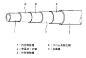
図1は、本発明のホースの一実施の形態を示している。この実施の形態のホースは、6層構造の管状のものであり、内側から順に、内側樹脂層1,クロム系酸化膜A,金属膜B,金属めっき層2,クロム系酸化膜Aおよび外側樹脂層3が形成されている。
FIG. 1 shows an embodiment of the hose of the present invention. The hose of this embodiment is a six-layered tube, and in order from the inside, the
上記ホースは、例えば、つぎのようにして作製することができる。すなわち、まず、内側樹脂層1を押出成形する。ついで、この内側樹脂層1の外周面に、スパッタリング,イオンプレーティング,真空蒸着等の物理蒸着法により、クロム系酸化膜Aを形成する。つづいて、このクロム系酸化膜Aの外周面に、上記スパッタリング等の物理蒸着法により、金属膜Bを形成する。つぎに、この金属膜Bの外周面に、電解めっきまたは無電解めっきにより、金属めっき層2を形成する。ついで、この金属めっき層2の外周面に、上記スパッタリング等の物理蒸着法により、クロム系酸化膜Aを形成する。そして、このクロム系酸化膜Aの外周面に、外側樹脂層3を押出成形する。このようにして、上記ホースを作製することができる。
The hose can be produced as follows, for example. That is, first, the
なお、内側樹脂層1の外周面には、クロム系酸化膜Aの形成に先立って、そのクロム系酸化膜Aと内側樹脂層1との接着力を高めるために、プラズマ処理,コロナ放電処理,紫外線処理等の前処理を行ってもよい。
Prior to the formation of the chromium-based oxide film A, plasma treatment, corona discharge treatment, and the like are performed on the outer peripheral surface of the
上記ホースの製法において、金属膜Bの形成(スパッタリング等の物理蒸着法)は、減圧した反応炉内で行われ、その後の金属めっき層2の形成(電解めっきまたは無電解めっき)は、めっき液内で行われる。このため、金属膜Bを形成した後から、めっき液に浸ける(金属めっき層2を形成する工程に移る)までは、金属膜Bが空気(酸素)に触れないよう、不活性ガス(窒素ガス等)の雰囲気下で行われることが好ましい。これにより、金属膜Bの外周面に酸化皮膜が形成されることなく、金属めっき層2が形成されるため、金属膜Bと金属めっき層2との接着力が強くなり、しかも、その酸化皮膜の除去作業が不要であるからである。これに対して、上記不活性ガスの雰囲気下で行われない場合は、金属膜Bが空気(酸素)に触れるため、金属膜Bの表面に酸化皮膜が形成され、この酸化皮膜を介して上記金属めっき層2が形成することができない。このため、その金属めっき層2を形成するために、上記酸化皮膜を除去するためのエッチング等の処理が必要となり、少し時間を要する(10〜20分間程度)。
In the hose manufacturing method, the formation of the metal film B (physical vapor deposition method such as sputtering) is performed in a reduced pressure reactor, and the subsequent formation of the metal plating layer 2 (electrolytic plating or electroless plating) is performed using a plating solution. Done within. For this reason, an inert gas (nitrogen gas) is used so that the metal film B does not come into contact with air (oxygen) until the metal film B is immersed in the plating solution after the metal film B is formed (the process moves to the step of forming the metal plating layer 2). Etc.). Thereby, since the
このように、上記ホースでは、金属めっき層2の形成に先立って、内側樹脂層1の外周面に、スパッタリング等の物理蒸着法により、クロム系酸化膜Aと金属膜Bとを形成している。これにより、金属めっき層2を形成するために従来必要であった、内側樹脂層へのタルクの含有,内側樹脂層の外周面に対するエッチングおよびパラジウム定着を不要にしている。
As described above, in the hose, prior to the formation of the
すなわち、従来のように内側樹脂層にタルクを含有させると、内側樹脂層が割れ易く、製品の信頼性に欠けていた。これに対して、本発明のホースのように、金属めっき層2の形成に先立って、内側樹脂層1の外周面に、上記物理蒸着法により、クロム系酸化膜Aと金属膜Bとを形成すると、内側樹脂層1にタルクを含有させる必要がなくなり、その内側樹脂層1が割れ難くなっている。
That is, when talc is contained in the inner resin layer as in the prior art, the inner resin layer is easily broken and the reliability of the product is lacking. On the other hand, like the hose of the present invention, prior to the formation of the
しかも、従来行っていた内側樹脂層の外周面に対するエッチングおよびパラジウム定着には、かなりの時間(数十分間程度)を要し、生産性悪化の原因となっていた。これに対して、本発明のホースでは、上記のように、金属めっき層2の形成に先立って、内側樹脂層1の外周面に、上記物理蒸着法により、クロム系酸化膜Aと金属膜Bとを形成しているため、上記エッチングおよびパラジウム定着を行う必要がない。そして、上記クロム系酸化膜Aおよび金属膜Bの形成には、あまり時間を要さない(2〜3分間程度)。このため、本発明のホースの製法では、生産性が向上する。
In addition, the etching and palladium fixing on the outer peripheral surface of the inner resin layer, which has been conventionally performed, requires a considerable time (about several tens of minutes), which causes a deterioration in productivity. On the other hand, in the hose of the present invention, as described above, the chromium-based oxide film A and the metal film B are formed on the outer peripheral surface of the
また、上記内側樹脂層1と金属めっき層2との間においては、クロム系酸化膜Aは、樹脂(内側樹脂層1)との接着力が強く、金属膜Bとの接着力も強い。しかも、その金属膜Bと金属めっき層2との接着力も金属同士であるため強くなっている。これらのため、内側樹脂層1と金属めっき層2との接着力は、強くなっている。
Further, between the
さらに、上記金属めっき層2と外側樹脂層3との間においては、クロム系酸化膜Aは、金属めっき層2との接着力が強く、外側樹脂層3との接着力も強くなっている。このため、金属めっき層2と外側樹脂層3との接着力も強くなっている。
Further, between the
つぎに、上記ホースの寸法ならびにホースを構成する内側樹脂層1,クロム系酸化膜A,金属膜B,金属めっき層2および外側樹脂層3の寸法等について説明する。すなわち、上記ホースおよび各層等の寸法は、ホースの用途等によって異なり、特に限定されないが、例えば、上記ホースが燃料ホースの場合は、ホースの内径(内側樹脂層1の内径)は、2〜40mm(好ましくは2.5〜36mm)の範囲内に設定され、ホースの外径(外側樹脂層3の外径)は、3〜44mm(好ましくは4〜40mm)の範囲内に設定される。そして、内側樹脂層1の厚みは、0.02〜1.0mm(好ましくは0.05〜1.0mm)の範囲に設定される。また、クロム系酸化膜Aおよび金属膜Bの厚みは、それぞれ、5nm〜10μm(好ましくは10nm〜3μm)の範囲内に設定される。膜厚が薄すぎると、均一に成膜することが困難となり、燃料低透過性や層間接着性が劣る傾向がみられ、逆に膜厚が厚すぎると、割れ易くなり、コスト的にも高くなるからである。また、金属めっき層2の厚みは、1〜500μm(好ましくは1〜100μm)の範囲に設定される。また、外側樹脂層3の厚みは、0.2〜1.5mm(好ましくは0.3〜1.0mm)の範囲内に設定される。
Next, the dimensions of the hose and the dimensions of the
つぎに、上記ホースを構成する内側樹脂層1,クロム系酸化膜A,金属膜B,金属めっき層2および外側樹脂層3の形成材料等について説明する。
Next, materials for forming the
上記内側樹脂層1の形成材料は、ホースの用途や中空部に流す流体の種類等によって異なり、特に限定されないが、例えば、上記ホースを、燃料や冷媒に対する耐透過性に優れた低透過樹脂ホースとして使用する場合は、ポリアリーレンスルフィド(PAS)樹脂,ポリアミド樹脂,ポリアミドイミド樹脂,ポリイミド樹脂,ポリエステル樹脂等が用いられる。これらは単独でもしくは2種以上併せて用いられる。これらのなかでも、低透過性能に優れるとともに、外周面に形成されるクロム系酸化膜Aとの層間接着性に優れるという観点から、PAS樹脂,ポリアミド樹脂が好適に用いられる。
The material for forming the
特に、上記PAS樹脂のなかでも、コスト面等の観点から、ポリフェニレンスルフィド(PPS)樹脂が好ましい。また、上記ポリアミド樹脂としては、例えば、ポリアミド6(PA6),ポリアミド66(PA66),ポリアミドMXD6,ポリアミド9T(PA9T),ポリアミド6T(PA6T)等があげられる。また、上記ポリエステル樹脂としては、例えば、ポリエチレンテレフタレート(PET),ポリブチレンテレフタレート(PBT),ポリエチレンナフタレート(PEN),ポリブチレンナフタレート(PBN)等があげられる。 In particular, among the PAS resins, polyphenylene sulfide (PPS) resin is preferable from the viewpoint of cost and the like. Examples of the polyamide resin include polyamide 6 (PA6), polyamide 66 (PA66), polyamide MXD6, polyamide 9T (PA9T), polyamide 6T (PA6T), and the like. Examples of the polyester resin include polyethylene terephthalate (PET), polybutylene terephthalate (PBT), polyethylene naphthalate (PEN), polybutylene naphthalate (PBN), and the like.
上記クロム系酸化膜Aの金属材料としては、特に限定されないが、例えば、酸化クロム、またはクロムを含有する金属の酸化物〔例えば、ステンレス(SUS)酸化物,ニッケル−クロム酸化物等〕があげられ、クロム以外の異種金属、もしくはクロム系酸化物以外の金属酸化物等を併用しても差し支えない。上記クロム系酸化膜Aは、上記物理蒸着法により、クロムもしくはクロム含有合金材料を成膜時に酸素と反応させるか、もしくはクロム含有酸化物材料を用いて成膜すること等によって形成することができる。 The metal material of the chromium-based oxide film A is not particularly limited, and examples thereof include chromium oxide or a metal oxide containing chromium (for example, stainless steel (SUS) oxide, nickel-chromium oxide, etc.). In addition, different metals other than chromium or metal oxides other than chromium-based oxides may be used in combination. The chromium-based oxide film A can be formed by reacting chromium or a chromium-containing alloy material with oxygen at the time of film formation or forming a film using a chromium-containing oxide material by the physical vapor deposition method. .
上記金属膜Bの金属材料としては、特に限定されないが、例えば、アルミニウム,マグネシウム,鉄,銅,ニッケル,チタン,クロム,ステンレス,タンタル,コバルト,パラジウム,金,プラチナ,銀,炭素,シリコン,モリブデン,タングステン,セレン,錫,インジウム,亜鉛,バナジウム,ジルコン,イットリウムもしくはこれらの合金等があげられる。これらは単独でもしくは2種以上併せて用いられる。これらのなかでも、金属めっき層2およびクロム系酸化膜Aとの接着性,成膜速度の観点から、ニッケル−クロム合金,クロム,ステンレスが好ましい。
The metal material of the metal film B is not particularly limited. For example, aluminum, magnesium, iron, copper, nickel, titanium, chromium, stainless steel, tantalum, cobalt, palladium, gold, platinum, silver, carbon, silicon, molybdenum , Tungsten, selenium, tin, indium, zinc, vanadium, zircon, yttrium, or alloys thereof. These may be used alone or in combination of two or more. Among these, nickel-chromium alloy, chromium, and stainless steel are preferable from the viewpoints of adhesion with the
上記金属めっき層2に用いる金属材料としては、特に限定はないが、例えば、ニッケル,銅,銀,金,クロム,アルミニウム,亜鉛,錫,コバルト,タングステン,白金,パラジウムおよびこれらの2種以上の元素を含む合金材料等があげられる。これらのなかでも、耐振動性,耐腐食性の観点から、ニッケル,ニッケル合金が好ましい。また、上記金属めっき層2の形成は、電解めっきでも無電解めっきでもよいが、上記金属膜Bとの接着力を高める観点から、電解めっきが好ましい。
The metal material used for the
上記外側樹脂層3の形成材料も、特に限定されないが、内周面に形成されているクロム系酸化膜Aとの層間接着性に優れるという観点から、ポリアミド樹脂が好ましい。特に、上記ホースを、自動車の燃料ホース等に用いる場合は、耐塩化カルシウム性,耐候性,耐衝撃性等の観点から、ポリアミド11(PA11),ポリアミド12(PA12),ポリアミド610(PA610),ポリアミド612(PA612)等の脂肪族ポリアミド樹脂、もしくはこれらとポリエーテルとの共重合体、例えば、ポリアミド6−ポリエーテル共重合体,ポリアミド12−ポリエーテル共重合体等がより好適に用いられる。これらは単独でもしくは2種以上併せて用いられる。
The material for forming the
なお、上記実施の形態では、内側樹脂層1と金属めっき層2との間に、内側から順にクロム系酸化膜Aと金属膜Bとの2層を介在させたが、内側樹脂層1の外周面にクロム系酸化膜Aが形成され、金属膜Bの外周面に金属めっき層2が形成されていれば、他でもよく、例えば、4層(クロム系酸化膜A/金属膜B/クロム系酸化膜A/金属膜B),6層(クロム系酸化膜A/金属膜B/クロム系酸化膜A/金属膜B/クロム系酸化膜A/金属膜B)等を介在させてもよい。また、金属めっき層2と外側樹脂層3との間についても、上記実施の形態では、クロム系酸化膜Aの1層を介在させたが、金属めっき層2との接着力が強く、クロム系酸化膜Aの外周面に外側樹脂層3が形成されていれば、他でもよく、例えば、2層(金属膜B/クロム系酸化膜A),3層(クロム系酸化膜A/金属膜B/クロム系酸化膜A),4層(金属膜B/クロム系酸化膜A/金属膜B/クロム系酸化膜A)等を介在させてもよい。
In the above embodiment, two layers of the chromium-based oxide film A and the metal film B are interposed between the
また、内側樹脂層1の内周面側,外側樹脂層3の外周面側に、他の層を形成しても差し支えない。
Further, other layers may be formed on the inner peripheral surface side of the
本発明のホースは、自動車や輸送機器(飛行機,フォークリフト,ショベルカー,クレーン等の産業用輸送車両、鉄道車両等)等に用いられる、ガソリン,アルコール混合ガソリン(ガソホール),アルコール,水素,軽油,ジメチルエーテル,ディーゼル,CNG(圧縮天然ガス),LPG(液化石油ガス)等の燃料輸送用ホース、エアコン・ラジエター等に用いられるフロン,代替フロン,水,二酸化炭素等の冷媒輸送用ホース、または、様々な機器に用いられている流体圧ホース等に好適に用いられる。 The hose of the present invention is used for automobiles and transportation equipment (industrial transportation vehicles such as airplanes, forklifts, excavators, cranes, railway vehicles, etc.), etc., gasoline, alcohol mixed gasoline (gasohol), alcohol, hydrogen, light oil, Fuel transport hoses such as dimethyl ether, diesel, CNG (compressed natural gas), LPG (liquefied petroleum gas), chlorofluorocarbons used in air conditioners and radiators, alternative chlorofluorocarbons, coolant transport hoses such as water and carbon dioxide, or various It is preferably used for a fluid pressure hose used in various devices.
つぎに、実施例について比較例と併せて説明する。 Next, examples will be described together with comparative examples.
まず、下記に示す、内側樹脂層および外側樹脂層の形成材料、ならびに電解めっき用のワット浴(めっき液)を準備した。 First, materials for forming an inner resin layer and an outer resin layer, and a watt bath (plating solution) for electroplating shown below were prepared.
〔PPS樹脂(内側樹脂層の形成材料)〕
東レ社製、トレリナA670X01
[PPS resin (material for forming the inner resin layer)]
Made by Toray Industries, Torelina A670X01
〔PA12樹脂(外側樹脂層の形成材料)〕
PA12(エムス社製、グリルアミドL25AH、末端アミノ基濃度:60μ当量/g)
[PA12 resin (material for forming the outer resin layer)]
PA12 (manufactured by EMS, Grillamide L25AH, terminal amino group concentration: 60 μeq / g)
〔ワット浴の液組成,pH,温度〕
硫酸ニッケル :250g/リットル
塩化ニッケル : 45g/リットル
ほう酸 : 40g/リットル
ピット防止剤(奥野製薬工業社製、アクナH) : 2ml/リットル
一次光沢剤(奥野製薬工業社製、Mu−2) : 5ml/リットル
pH:4.2
温度:50℃
[Watt bath liquid composition, pH, temperature]
Nickel sulfate: 250 g / liter Nickel chloride: 45 g / liter Boric acid: 40 g / liter Pit inhibitor (Okuno Pharmaceutical Co., Ltd., Acuna H): 2 ml / liter Primary brightener (Okuno Pharmaceutical Co., Ltd., Mu-2): 5 ml / L pH: 4.2
Temperature: 50 ° C
つぎに、上記形成材料等を用いて、下記のように、燃料輸送用ホースを作製した。 Next, a hose for transporting fuel was produced as described below using the above-described forming material and the like.
〔実施例1〜3〕
まず、上記PPS樹脂を用いて、内側樹脂層を押出成形した。ついで、この内側樹脂層の外周面に、DCマグネトロンスパッタリング装置を用いて、後記の表2に示す条件にて、スパッタリングにより、クロム系酸化膜を形成し、つづいて、後記の表2に示す条件にて、スパッタリングにより、金属膜を形成した。その後、それを、窒素ガス雰囲気下で、上記DCマグネトロンスパッタリング装置から取り出し、すぐに、上記ワット浴に浸けた。そして、上記金属膜の外周面に、上記ワット浴にて、電流密度1A/dm2 で5分間、電解めっきを行い、ニッケルめっき層(金属めっき層)を形成した。つぎに、それを上記ワット浴から取り出し、ニッケルめっき層の外周面を乾燥させた後、そのニッケルめっき層の外周面に、DCマグネトロンスパッタリング装置を用いて、後記の表2に示す条件にて、スパッタリングにより、クロム系酸化膜を形成した。そして、このクロム系酸化膜の外周面に、外側樹脂層を押出成形した。このとき、内側樹脂層から外側樹脂層までの全体の厚みが1.5mmになるようにした。このようにして、図1に示す6層構造の燃料輸送用ホース(内径33mm、外径36mm)を作製した。
[Examples 1-3]
First, the inner resin layer was extrusion molded using the PPS resin. Next, a chromium-based oxide film is formed on the outer peripheral surface of the inner resin layer by sputtering under the conditions shown in Table 2 below using a DC magnetron sputtering apparatus. Subsequently, the conditions shown in Table 2 below are given. Then, a metal film was formed by sputtering. Thereafter, it was removed from the DC magnetron sputtering apparatus under a nitrogen gas atmosphere and immediately immersed in the watt bath. Then, electrolytic plating was performed on the outer peripheral surface of the metal film in the Watt bath at a current density of 1 A / dm 2 for 5 minutes to form a nickel plating layer (metal plating layer). Next, after removing it from the watt bath and drying the outer peripheral surface of the nickel plating layer, the outer peripheral surface of the nickel plating layer was subjected to the conditions shown in Table 2 below using a DC magnetron sputtering apparatus. A chromium-based oxide film was formed by sputtering. And the outer side resin layer was extrusion-molded on the outer peripheral surface of this chromium type oxide film. At this time, the entire thickness from the inner resin layer to the outer resin layer was set to 1.5 mm. In this way, a six-layer fuel transportation hose (inner diameter: 33 mm, outer diameter: 36 mm) shown in FIG. 1 was produced.
〔比較例1〕
まず、上記PPS樹脂を用いて、内側樹脂層を押出成形した。ついで、この内側樹脂層を上記ワット浴に浸け、この内側樹脂層の外周面に直接、上記実施例と同様にして電解めっきを行ったが、ニッケルめっき層(金属めっき層)は形成されなかった。そこで、上記内側樹脂層をアルカリニッケル液(奥野製薬工業社製、TMP−化学ニッケル)に浸け、40℃で5分間、無電解ニッケルめっきを行ったが、ニッケルめっき層(金属めっき層)は形成されなかった。そして、この内側樹脂層のみからなる燃料輸送用ホース(内径33mm、外径33.2mm)を比較例1とした。
[Comparative Example 1]
First, the inner resin layer was extrusion molded using the PPS resin. Next, the inner resin layer was immersed in the Watt bath and electrolytic plating was performed directly on the outer peripheral surface of the inner resin layer in the same manner as in the above example, but no nickel plating layer (metal plating layer) was formed. . Therefore, the inner resin layer was immersed in an alkaline nickel solution (TMP-chemical nickel, manufactured by Okuno Pharmaceutical Co., Ltd.) and subjected to electroless nickel plating at 40 ° C. for 5 minutes, but a nickel plating layer (metal plating layer) was formed. Was not. A fuel transport hose (inner diameter 33 mm, outer diameter 33.2 mm) consisting only of this inner resin layer was used as Comparative Example 1.
〔比較例2〕
まず、上記PPS樹脂を用いて、内側樹脂層を押出成形した。ついで、この内側樹脂層の外周面に、DCマグネトロンスパッタリング装置を用いて、後記の表2に示す条件にて、スパッタリングにより、Ni−Cr金属膜のみを形成した。それ以降は、上記実施例と同様にして、ニッケルめっき層(金属めっき層),クロム系酸化膜,外側樹脂層を順に形成した。このようにして、5層構造の燃料輸送用ホース(内径33mm、外径36mm)を作製した。
[Comparative Example 2]
First, the inner resin layer was extrusion molded using the PPS resin. Subsequently, only a Ni—Cr metal film was formed on the outer peripheral surface of the inner resin layer by sputtering under the conditions shown in Table 2 below using a DC magnetron sputtering apparatus. Thereafter, a nickel plating layer (metal plating layer), a chromium-based oxide film, and an outer resin layer were formed in this order in the same manner as in the above example. Thus, a fuel transport hose (inner diameter: 33 mm, outer diameter: 36 mm) having a five-layer structure was produced.
〔比較例3〕
まず、上記PPS樹脂を用いて、内側樹脂層を押出成形した。ついで、この内側樹脂層の外周面に直接、上記実施例と同様にして外側樹脂層を押出成形した。このようにして、2層構造の燃料輸送用ホース(内径33mm、外径36mm)を作製した。
[Comparative Example 3]
First, the inner resin layer was extrusion molded using the PPS resin. Then, the outer resin layer was extruded directly on the outer peripheral surface of the inner resin layer in the same manner as in the above example. Thus, a fuel transport hose (inner diameter: 33 mm, outer diameter: 36 mm) having a two-layer structure was produced.
このようにして得られた実施例1〜3および比較例2,3の各燃料輸送用ホースを用い、下記の基準に従って、各特性の評価を行った。これらの結果を、後記の表1に併せて示した。 Using the fuel transport hoses of Examples 1 to 3 and Comparative Examples 2 and 3 thus obtained, each characteristic was evaluated according to the following criteria. These results are also shown in Table 1 below.
〔透過係数〕
上記各燃料輸送用ホースを長手方向に切り開いた後、直径56mmの円盤状に打ち抜き、各サンプルを作製した。そして、差圧式・蒸気透過率測定装置(GTRテック社製、GTR−30XATG)を用いて,上記サンプルにおける、市販レギュラーガソリンと、エタノールとを90:10(体積割合)で混合したアルコール添加ガソリンの透過係数を、40℃で2週間測定した。なお、表中の透過係数は、2週間後の数値を示す。
[Transmission coefficient]
Each fuel transport hose was cut open in the longitudinal direction, and then punched into a disk shape having a diameter of 56 mm to prepare each sample. Then, using a differential pressure type / vapor permeability measuring apparatus (GTR-30XATG, manufactured by GTR Tech), commercially available regular gasoline and ethanol mixed in ethanol at 90:10 (volume ratio) in the above sample. The permeability coefficient was measured at 40 ° C. for 2 weeks. In addition, the permeability coefficient in a table | surface shows the numerical value after 2 weeks.
〔剥離強度〕
各燃料輸送用ホースを10mm幅で短冊状に切断して、サンプルを作製した。そして、各サンプルの先端部の各層を剥離し、その剥離した内側樹脂層と金属めっき層の各層の先端部を引張試験機(オリエンテック社製)の各チャックに挟み、引張速度50mm/分の条件で、内側樹脂層/金属めっき層間の180度剥離強度(N/cm)を測定した。同様にして、金属めっき層/外側樹脂層間(比較例3は、内側樹脂層/外側樹脂層間)の180度剥離強度(N/cm)を測定した。なお、剥離強度が20N/cm以上であれば、層間接着性が良好であると考えられる。
[Peel strength]
Each fuel transport hose was cut into a strip shape with a width of 10 mm to prepare a sample. And each layer of the tip part of each sample is peeled off, and the tip part of each layer of the peeled inner resin layer and metal plating layer is sandwiched between chucks of a tensile tester (made by Orientec Co., Ltd.), and the tensile speed is 50 mm / min. Under the conditions, 180 degree peel strength (N / cm) between the inner resin layer / metal plating layer was measured. Similarly, the 180 degree peel strength (N / cm) between the metal plating layer / outer resin layer (Comparative Example 3, inner resin layer / outer resin layer) was measured. If the peel strength is 20 N / cm or more, it is considered that the interlayer adhesion is good.

上記結果から、実施例1〜3の燃料輸送用ホースは、ガソリン低透過性および層間接着性に優れていることがわかる。そして、比較例1から、内側樹脂層の外周面に何も処理しなければ、金属めっき層を形成できないことがわかる。また、実施例1〜3と比較例2との比較から、内側樹脂層の外周面にクロム系酸化膜を形成しなければ、内側樹脂層/金属めっき層間の剥離強度が小さく、その層間接着性に劣ることがわかる。また、比較例3の燃料輸送用ホースは、内側樹脂層と外側樹脂層とが接着されておらず、実施例1〜3との比較からもガソリン低透過性に劣っていることがわかる。その理由は、クロム系酸化膜,金属膜および金属めっき層が形成されていないからであると判断できる。 From the above results, it can be seen that the fuel transportation hoses of Examples 1 to 3 are excellent in gasoline low permeability and interlayer adhesion. And it can be seen from Comparative Example 1 that the metal plating layer cannot be formed unless the outer peripheral surface of the inner resin layer is treated. Further, from comparison between Examples 1 to 3 and Comparative Example 2, if a chromium-based oxide film is not formed on the outer peripheral surface of the inner resin layer, the peel strength between the inner resin layer / metal plating layer is small, and the interlayer adhesion It turns out that it is inferior to. Moreover, the fuel transport hose of Comparative Example 3 shows that the inner resin layer and the outer resin layer are not adhered, and the comparison with Examples 1 to 3 shows that the gasoline low permeability is inferior. The reason can be determined that the chromium oxide film, the metal film, and the metal plating layer are not formed.
1 内側樹脂層
2 金属めっき層
3 外側樹脂層
A クロム系酸化膜
B 金属膜
DESCRIPTION OF
Claims (3)
Priority Applications (2)
| Application Number | Priority Date | Filing Date | Title |
|---|---|---|---|
| JP2005082225A JP4479552B2 (en) | 2005-03-22 | 2005-03-22 | Hose and its manufacturing method |
| US11/385,753 US7434599B2 (en) | 2005-03-22 | 2006-03-22 | Hose and method of producing the same |
Applications Claiming Priority (1)
| Application Number | Priority Date | Filing Date | Title |
|---|---|---|---|
| JP2005082225A JP4479552B2 (en) | 2005-03-22 | 2005-03-22 | Hose and its manufacturing method |
Publications (2)
| Publication Number | Publication Date |
|---|---|
| JP2006266318A JP2006266318A (en) | 2006-10-05 |
| JP4479552B2 true JP4479552B2 (en) | 2010-06-09 |
Family
ID=37033988
Family Applications (1)
| Application Number | Title | Priority Date | Filing Date |
|---|---|---|---|
| JP2005082225A Expired - Fee Related JP4479552B2 (en) | 2005-03-22 | 2005-03-22 | Hose and its manufacturing method |
Country Status (2)
| Country | Link |
|---|---|
| US (1) | US7434599B2 (en) |
| JP (1) | JP4479552B2 (en) |
Families Citing this family (11)
| Publication number | Priority date | Publication date | Assignee | Title |
|---|---|---|---|---|
| JP2006118669A (en) * | 2004-10-25 | 2006-05-11 | Sanoh Industrial Co Ltd | Resin tube |
| JP4544125B2 (en) * | 2005-10-17 | 2010-09-15 | 東海ゴム工業株式会社 | Low-permeability resin hose and manufacturing method thereof |
| JP4544129B2 (en) * | 2005-10-25 | 2010-09-15 | 東海ゴム工業株式会社 | Low-permeability resin hose and manufacturing method thereof |
| JP4896703B2 (en) * | 2006-12-26 | 2012-03-14 | 東海ゴム工業株式会社 | Nickel electroplating film and its manufacturing method |
| DE102010009796A1 (en) * | 2010-03-01 | 2011-09-01 | Rehau Ag + Co. | Use of a tube for the transport of pure hydrogen |
| CA2801874C (en) * | 2010-06-09 | 2014-09-09 | Sanoh Kogyo Kabushiki Kaisha | Metal pipe for vehicle piping and method of surface-treating the same |
| JP2013538154A (en) * | 2010-09-03 | 2013-10-10 | アエラズール エス.エー. | Aircraft thermoplastic hose |
| US9746108B2 (en) * | 2014-03-04 | 2017-08-29 | W.E. Hall Company, Inc. | Composite underground pipe structure |
| JP6467195B2 (en) | 2014-11-10 | 2019-02-06 | 三桜工業株式会社 | Coated metal pipe for vehicle piping |
| JP7179460B2 (en) * | 2015-09-28 | 2022-11-29 | 株式会社ブリヂストン | Resin materials for hoses, hose pipes and hoses |
| US12498076B2 (en) * | 2022-06-23 | 2025-12-16 | Dynaflex Products | Method of plating an automotive exhaust pipe |
Family Cites Families (10)
| Publication number | Priority date | Publication date | Assignee | Title |
|---|---|---|---|---|
| JPS581076A (en) * | 1981-06-26 | 1983-01-06 | Nisshin Steel Co Ltd | Surface treatment method of high nickel-iron alloy steel |
| US4467002A (en) * | 1981-12-15 | 1984-08-21 | Raychem Limited | Dimensionally-recoverable article |
| US4606953A (en) * | 1983-06-23 | 1986-08-19 | Nippon Steel Corporation | Polypropylene coated steel pipe |
| US4916031A (en) * | 1985-11-20 | 1990-04-10 | Toyo Seikan Kaisha, Ltd. | Surface-treated steel plate and bonded structure of metal material |
| US5271977A (en) * | 1989-02-10 | 1993-12-21 | Bridgestone Corporation | Low permeable rubber hose |
| JPH04131581A (en) * | 1990-09-25 | 1992-05-06 | Bridgestone Corp | Low permeable rubber hose |
| JPH08269723A (en) | 1995-03-27 | 1996-10-15 | Toyoda Gosei Co Ltd | Resin molded goods having plating layer and their production |
| GB2311114B (en) * | 1996-03-15 | 1999-04-28 | T & N Technology Ltd | Convoluted flexible protective sleeves |
| US6546963B2 (en) * | 2000-12-08 | 2003-04-15 | Halter Marine, Inc. | Fire resistant piping system |
| US7033679B2 (en) * | 2001-01-25 | 2006-04-25 | Kyocera Optec Co., Ltd. | Metal film and metal film-coated member, metal oxide film and metal oxide film-coated member, thin film forming apparatus and thin film forming method for producing metal film and metal oxide film |
-
2005
- 2005-03-22 JP JP2005082225A patent/JP4479552B2/en not_active Expired - Fee Related
-
2006
- 2006-03-22 US US11/385,753 patent/US7434599B2/en not_active Expired - Lifetime
Also Published As
| Publication number | Publication date |
|---|---|
| US7434599B2 (en) | 2008-10-14 |
| US20060213569A1 (en) | 2006-09-28 |
| JP2006266318A (en) | 2006-10-05 |
Similar Documents
| Publication | Publication Date | Title |
|---|---|---|
| JP4479552B2 (en) | Hose and its manufacturing method | |
| US6652939B2 (en) | Low permeation nylon tube with aluminum barrier layer | |
| KR920009633B1 (en) | Heat and corrosion resistant steel pipe with multilayer coating | |
| US6591871B2 (en) | Low permeation polybutylene terephthalate and polybutylene naphthalate fuel and vapor tubes | |
| JP4383487B2 (en) | Metal-clad laminate and method for producing metal-clad laminate | |
| AU2002341655A1 (en) | Low permeation nylon tube with aluminium barrier layer | |
| CN100503889C (en) | Non-hexavalent chromium-based corrosion-resistant coating film having metal layer and resin layer with excellent adhesion to resin layer | |
| CN103097583A (en) | Steel plate for containers and manufacturing method for same | |
| TWI597161B (en) | Metallic external material with resin film and its manufacturing method | |
| CN103026046A (en) | Steel fuel conveying pipe | |
| US6517118B2 (en) | Hose device for fuel transportation | |
| CN103208320A (en) | Plate-like Conductor For A Busbar And The Busbar Consisting Of The Plate-like Conductor | |
| US6974614B2 (en) | Low permeation high density polyethylene tube with aluminum barrier layer | |
| EP1304519A2 (en) | Process for making a fluid-impermeable layer, and an impermeable hose | |
| JP5305373B2 (en) | Resin piping | |
| JP4562510B2 (en) | Multi-layer resin tube | |
| JP2012219370A (en) | Surface treatment structure of piping for vehicle | |
| KR20150009988A (en) | Pipe having heat-resistant corrosion-resistant plating layer that has excellent processability | |
| CN113544315A (en) | Aluminum base material | |
| JP2009052102A (en) | Surface-treated steel sheet, resin-coated steel sheet, can and can lid | |
| JP2002060972A (en) | Stainless steel sheet for automobile fuel tank | |
| JPH09285828A (en) | Ironing method for resin-coated metal plate and its processing die | |
| JP2006212966A (en) | Low-permeability resin hose and manufacturing method thereof | |
| JP2008297588A (en) | High tensile strength steel pipe for high pressure piping of automobile | |
| JP2002228069A (en) | Resin connector |
Legal Events
| Date | Code | Title | Description |
|---|---|---|---|
| A621 | Written request for application examination |
Free format text: JAPANESE INTERMEDIATE CODE: A621 Effective date: 20070913 |
|
| A977 | Report on retrieval |
Free format text: JAPANESE INTERMEDIATE CODE: A971007 Effective date: 20100129 |
|
| TRDD | Decision of grant or rejection written | ||
| A01 | Written decision to grant a patent or to grant a registration (utility model) |
Free format text: JAPANESE INTERMEDIATE CODE: A01 Effective date: 20100223 |
|
| A01 | Written decision to grant a patent or to grant a registration (utility model) |
Free format text: JAPANESE INTERMEDIATE CODE: A01 |
|
| A61 | First payment of annual fees (during grant procedure) |
Free format text: JAPANESE INTERMEDIATE CODE: A61 Effective date: 20100308 |
|
| FPAY | Renewal fee payment (event date is renewal date of database) |
Free format text: PAYMENT UNTIL: 20130326 Year of fee payment: 3 |
|
| R150 | Certificate of patent or registration of utility model |
Free format text: JAPANESE INTERMEDIATE CODE: R150 |
|
| FPAY | Renewal fee payment (event date is renewal date of database) |
Free format text: PAYMENT UNTIL: 20130326 Year of fee payment: 3 |
|
| FPAY | Renewal fee payment (event date is renewal date of database) |
Free format text: PAYMENT UNTIL: 20140326 Year of fee payment: 4 |
|
| LAPS | Cancellation because of no payment of annual fees |