JP5773515B2 - Steel fuel pumping pipe - Google Patents
Steel fuel pumping pipe Download PDFInfo
- Publication number
- JP5773515B2 JP5773515B2 JP2010165881A JP2010165881A JP5773515B2 JP 5773515 B2 JP5773515 B2 JP 5773515B2 JP 2010165881 A JP2010165881 A JP 2010165881A JP 2010165881 A JP2010165881 A JP 2010165881A JP 5773515 B2 JP5773515 B2 JP 5773515B2
- Authority
- JP
- Japan
- Prior art keywords
- fuel
- pipe
- plating layer
- layer
- gasoline
- Prior art date
- Legal status (The legal status is an assumption and is not a legal conclusion. Google has not performed a legal analysis and makes no representation as to the accuracy of the status listed.)
- Active
Links
Images


Classifications
-
- F—MECHANICAL ENGINEERING; LIGHTING; HEATING; WEAPONS; BLASTING
- F02—COMBUSTION ENGINES; HOT-GAS OR COMBUSTION-PRODUCT ENGINE PLANTS
- F02M—SUPPLYING COMBUSTION ENGINES IN GENERAL WITH COMBUSTIBLE MIXTURES OR CONSTITUENTS THEREOF
- F02M37/00—Apparatus or systems for feeding liquid fuel from storage containers to carburettors or fuel-injection apparatus; Arrangements for purifying liquid fuel specially adapted for, or arranged on, internal-combustion engines
-
- F—MECHANICAL ENGINEERING; LIGHTING; HEATING; WEAPONS; BLASTING
- F16—ENGINEERING ELEMENTS AND UNITS; GENERAL MEASURES FOR PRODUCING AND MAINTAINING EFFECTIVE FUNCTIONING OF MACHINES OR INSTALLATIONS; THERMAL INSULATION IN GENERAL
- F16L—PIPES; JOINTS OR FITTINGS FOR PIPES; SUPPORTS FOR PIPES, CABLES OR PROTECTIVE TUBING; MEANS FOR THERMAL INSULATION IN GENERAL
- F16L9/00—Rigid pipes
- F16L9/02—Rigid pipes of metal
-
- F—MECHANICAL ENGINEERING; LIGHTING; HEATING; WEAPONS; BLASTING
- F02—COMBUSTION ENGINES; HOT-GAS OR COMBUSTION-PRODUCT ENGINE PLANTS
- F02M—SUPPLYING COMBUSTION ENGINES IN GENERAL WITH COMBUSTIBLE MIXTURES OR CONSTITUENTS THEREOF
- F02M55/00—Fuel-injection apparatus characterised by their fuel conduits or their venting means; Arrangements of conduits between fuel tank and pump F02M37/00
- F02M55/02—Conduits between injection pumps and injectors, e.g. conduits between pump and common-rail or conduits between common-rail and injectors
-
- F—MECHANICAL ENGINEERING; LIGHTING; HEATING; WEAPONS; BLASTING
- F16—ENGINEERING ELEMENTS AND UNITS; GENERAL MEASURES FOR PRODUCING AND MAINTAINING EFFECTIVE FUNCTIONING OF MACHINES OR INSTALLATIONS; THERMAL INSULATION IN GENERAL
- F16L—PIPES; JOINTS OR FITTINGS FOR PIPES; SUPPORTS FOR PIPES, CABLES OR PROTECTIVE TUBING; MEANS FOR THERMAL INSULATION IN GENERAL
- F16L58/00—Protection of pipes or pipe fittings against corrosion or incrustation
- F16L58/02—Protection of pipes or pipe fittings against corrosion or incrustation by means of internal or external coatings
- F16L58/04—Coatings characterised by the materials used
- F16L58/08—Coatings characterised by the materials used by metal
-
- F—MECHANICAL ENGINEERING; LIGHTING; HEATING; WEAPONS; BLASTING
- F02—COMBUSTION ENGINES; HOT-GAS OR COMBUSTION-PRODUCT ENGINE PLANTS
- F02M—SUPPLYING COMBUSTION ENGINES IN GENERAL WITH COMBUSTIBLE MIXTURES OR CONSTITUENTS THEREOF
- F02M2200/00—Details of fuel-injection apparatus, not otherwise provided for
- F02M2200/05—Fuel-injection apparatus having means for preventing corrosion
-
- F—MECHANICAL ENGINEERING; LIGHTING; HEATING; WEAPONS; BLASTING
- F02—COMBUSTION ENGINES; HOT-GAS OR COMBUSTION-PRODUCT ENGINE PLANTS
- F02M—SUPPLYING COMBUSTION ENGINES IN GENERAL WITH COMBUSTIBLE MIXTURES OR CONSTITUENTS THEREOF
- F02M2200/00—Details of fuel-injection apparatus, not otherwise provided for
- F02M2200/90—Selection of particular materials
- F02M2200/9038—Coatings
-
- Y—GENERAL TAGGING OF NEW TECHNOLOGICAL DEVELOPMENTS; GENERAL TAGGING OF CROSS-SECTIONAL TECHNOLOGIES SPANNING OVER SEVERAL SECTIONS OF THE IPC; TECHNICAL SUBJECTS COVERED BY FORMER USPC CROSS-REFERENCE ART COLLECTIONS [XRACs] AND DIGESTS
- Y10—TECHNICAL SUBJECTS COVERED BY FORMER USPC
- Y10T—TECHNICAL SUBJECTS COVERED BY FORMER US CLASSIFICATION
- Y10T428/00—Stock material or miscellaneous articles
- Y10T428/12—All metal or with adjacent metals
- Y10T428/12486—Laterally noncoextensive components [e.g., embedded, etc.]
-
- Y—GENERAL TAGGING OF NEW TECHNOLOGICAL DEVELOPMENTS; GENERAL TAGGING OF CROSS-SECTIONAL TECHNOLOGIES SPANNING OVER SEVERAL SECTIONS OF THE IPC; TECHNICAL SUBJECTS COVERED BY FORMER USPC CROSS-REFERENCE ART COLLECTIONS [XRACs] AND DIGESTS
- Y10—TECHNICAL SUBJECTS COVERED BY FORMER USPC
- Y10T—TECHNICAL SUBJECTS COVERED BY FORMER US CLASSIFICATION
- Y10T428/00—Stock material or miscellaneous articles
- Y10T428/12—All metal or with adjacent metals
- Y10T428/12493—Composite; i.e., plural, adjacent, spatially distinct metal components [e.g., layers, joint, etc.]
- Y10T428/12771—Transition metal-base component
- Y10T428/12785—Group IIB metal-base component
- Y10T428/12792—Zn-base component
- Y10T428/12799—Next to Fe-base component [e.g., galvanized]
-
- Y—GENERAL TAGGING OF NEW TECHNOLOGICAL DEVELOPMENTS; GENERAL TAGGING OF CROSS-SECTIONAL TECHNOLOGIES SPANNING OVER SEVERAL SECTIONS OF THE IPC; TECHNICAL SUBJECTS COVERED BY FORMER USPC CROSS-REFERENCE ART COLLECTIONS [XRACs] AND DIGESTS
- Y10—TECHNICAL SUBJECTS COVERED BY FORMER USPC
- Y10T—TECHNICAL SUBJECTS COVERED BY FORMER US CLASSIFICATION
- Y10T428/00—Stock material or miscellaneous articles
- Y10T428/12—All metal or with adjacent metals
- Y10T428/12493—Composite; i.e., plural, adjacent, spatially distinct metal components [e.g., layers, joint, etc.]
- Y10T428/12771—Transition metal-base component
- Y10T428/12861—Group VIII or IB metal-base component
- Y10T428/12937—Co- or Ni-base component next to Fe-base component
Description
本発明は、ガソリン直噴エンジンシステムにおける燃料をエンジンに供給する配管に関するものである。
特に、本発明は、粗悪な腐食性成分を含む燃料に対して耐性のある配管に関するものである。
The present invention relates to piping for supplying fuel to an engine in a gasoline direct injection engine system.
In particular, the present invention relates to piping that is resistant to fuels containing poor corrosive components.
近年、燃費向上による環境負荷低減を目的として自動車産業で開発・市場投入が進んでいるガソリン直噴エンジンシステムでは、図1に示すように、燃料(ガソリン)を燃料タンク10からポンプ20を経てエンジン(図示せず)の直噴レール30に供給する配管1に対して、既存の各気筒吸気ポート噴射(MPI:Multi Point Injection)エンジンよりも高耐圧性・高機密性が要求されている(特許文献1、2など参照)。
In recent years, in a gasoline direct injection engine system that has been developed and put on the market in the automobile industry for the purpose of reducing the environmental load by improving fuel efficiency, as shown in FIG. 1, fuel (gasoline) is sent from a
また、同じく環境負荷低減を目的としたバイオ由来のアルコール燃料に代表されるような代替燃料の市場拡大に加え、中国・インドに代表されるような新興国の台頭による自動車産業のグローバル化が進んだことにより、バイオ由来又は粗悪な環境下で供給された水分、塩類、および腐食性因子(主に酸)などを含有する腐食性成分を多く含む燃料(以下、「腐食性燃料」と称す)を用いて、ガソリン直噴エンジンを搭載した自動車が運用されることを基準として、それら粗悪な腐食性燃料に対しても耐性のある配管が要求されている。 In addition to expanding the market for alternative fuels, such as bio-derived alcohol fuels, which are also aimed at reducing environmental impacts, the globalization of the automobile industry is progressing due to the rise of emerging countries such as China and India. As a result, fuel that contains a lot of corrosive components containing moisture, salts, and corrosive factors (mainly acids) supplied in bio-derived or poor environments (hereinafter referred to as “corrosive fuel”) As a standard, automobiles equipped with a gasoline direct-injection engine are used as standard, and pipes that are resistant to such bad corrosive fuels are required.
このガソリン直噴エンジンシステムに使用される燃料の圧送配管(図1、符号1で示される)においては、自動車産業、特に製造拠点のグローバル化を踏まえた上で安定的な材料供給が可能であって、且つ前述の耐圧性、機密性、耐食性などの諸性能を有する仕様として、ステンレス系の材料に各種塑性加工(管末成形加工、曲げ加工等)や接合加工(ロウ付け加工等)を施して(ステンレス系材料特有の耐食性能により特異な表面処理を施すことをせず)製品とされたものが標準として最も多く採用されている。
なお、既存のMPIエンジンシステムで標準的に採用されるステンレス系材料よりも安価なスチール系の材料についても、要求性能が満たされる特定の製品については採用されている。
The fuel pressure-feed piping used in this gasoline direct-injection engine system (shown by
It should be noted that a steel material that is cheaper than a stainless steel material that is standardly adopted in an existing MPI engine system is also used for a specific product that satisfies the required performance.
しかしながら、塑性加工や接合加工が施されたステンレス系配管では、以下のような問題点が挙げられる。
(1)寒冷地や海洋沿岸地域における自動車使用環境特有の塩害に対する応力腐食割れ(SCC)。
(2)水分や塩類(特に塩素などの腐食性陰イオン)を高濃度含有し、直噴システムなどの高圧・高温条件で使用されることによって腐食性が極めて高くなっている燃料に対する耐食性。
(3)接合加工時の熱影響による、鋭敏化(SCCの発生危険度の上昇)や機械的性質低下(強度の低下)。
However, there are the following problems in stainless steel pipes subjected to plastic working and joining.
(1) Stress corrosion cracking (SCC) against salt damage peculiar to automobile use environments in cold regions and ocean coastal areas.
(2) Corrosion resistance to fuels that contain high concentrations of moisture and salts (especially corrosive anions such as chlorine) and are extremely corrosive when used under high-pressure and high-temperature conditions such as direct injection systems.
(3) Sensitization (increased risk of occurrence of SCC) and deterioration of mechanical properties (decrease in strength) due to thermal effects during bonding processing.
そのため、これらの問題によって製品加工条件、材質、製品仕様が制限され、工程の追加や高精度の要求によるコスト高や安定的な材料供給不能となるばかりか、製品実現が不可能となることもある。 For this reason, these problems limit product processing conditions, materials, and product specifications, resulting in not only high cost and stable material supply due to the addition of processes and high precision requirements, but also the realization of products. is there.
このようなステンレス系配管に対し、低炭素鋼などのスチール系配管は塑性加工や接合加工に伴う問題は、耐食性を除いて十分満足するものである。唯一かつ最大の問題点である耐食性についても、外部環境に起因する塩害に対して外表面にZn系やAl系の犠牲防食機構を有する防錆めっきを、腐食性燃料に対して内表面にNi系、Cr系、Co系、Sn系などのバリアー性に優れる防錆めっきを施すことによって、その耐食性を飛躍的に高められることが知られている。 In contrast to such stainless steel pipes, steel pipes such as low carbon steel are sufficiently satisfied with the problems associated with plastic working and joining, except for corrosion resistance. As for corrosion resistance, which is the only and greatest problem, anti-corrosion plating with a Zn-based or Al-based sacrificial anti-corrosion mechanism on the outer surface against salt damage caused by the external environment, and Ni on the inner surface against corrosive fuel. It is known that the corrosion resistance can be drastically improved by applying rust-preventive plating having excellent barrier properties such as Sn, Cr, Co, and Sn.
ただし、水分や塩類を含む腐食性燃料に対してはバリアー防食機構のみに特化した防錆めっきのみでは、腐食基点となり得るピンホール等の欠陥を完全に無くすために相当量の膜厚(例えば、数十μm〜百数十μmレベル)を施したり、複数の皮膜を複層化・複合化(合金化)したりする必要がある。しかし、その反面で厚膜あるいは複雑となったことによってコスト高となることはもちろん、皮膜強度や母材との密着強度が低下してめっき皮膜が破壊(亀裂)や脱離(剥離)を起してしまい、むしろバリアー性が低下して耐食性が悪くなって要求性能を満たすことができず、製品が実現できないケースもある。 However, for corrosive fuels containing moisture and salts, only a rust-preventing plating specialized only for the barrier anticorrosion mechanism has a considerable film thickness (for example, to completely eliminate defects such as pinholes that can become corrosion base points) Tens of μm to hundreds of tens of μm), and a plurality of coatings need to be multi-layered / composited (alloyed). However, on the other hand, the cost increases due to the thick film or complexity, and of course, the film strength and adhesion strength with the base material decrease, and the plating film breaks (cracks) and detaches (peels). In other words, the barrier property is lowered, the corrosion resistance is deteriorated, the required performance cannot be satisfied, and the product cannot be realized.
その対策として、耐塩害に優れるZn系やAl系の犠牲防食機構を有する防錆めっきを内表面にも施すことが考えられるが、犠牲防食機能を有するが故に腐食性燃料に防錆めっき成分であるZnやAlがイオンとして溶け出してしまい、これら溶出イオンが内燃機関各所に各種弊害をもたらす新たな問題の発生が懸念される。 As countermeasures, it may be possible to apply rust-proof plating with a Zn-based or Al-based sacrificial anti-corrosion mechanism with excellent salt damage resistance to the inner surface. There is a concern that some Zn and Al are dissolved as ions, and these elution ions cause various problems that cause various harmful effects on various parts of the internal combustion engine.
そこで本発明は、このような問題を解決する腐食性燃料に対する高い耐性を有すると共に直噴エンジンの機能を損なわずに信頼性を維持するガソリン直噴エンジンシステムにおける高圧ポンプと直噴レール間を繋ぐスチール製燃料圧送配管、およびV型ガソリンエンジンにおける直噴レール同士の連結用バイパス配管を提供するものである。 Therefore, the present invention connects a high-pressure pump and a direct-injection rail in a gasoline direct-injection engine system that has high resistance to a corrosive fuel that solves such problems and maintains reliability without impairing the function of the direct-injection engine. A steel fuel pressure feed pipe and a bypass pipe for connecting direct injection rails in a V-type gasoline engine are provided.
本発明では耐食性、特に腐食性燃料に対する燃料配管の内表面について鋭意研究を重ね、腐食性燃料に溶出するイオン量を極力低減した、腐食性燃料への耐性に優れる内表面処理を有するスチール製のガソリン用配管を発明したものである。 In the present invention, the corrosion resistance, particularly the inner surface of the fuel pipe for the corrosive fuel, has been earnestly studied, the amount of ions eluted into the corrosive fuel is reduced as much as possible, and the steel is made of steel having an inner surface treatment excellent in resistance to the corrosive fuel. Invented the piping for gasoline.
本発明の第1の発明は、ガソリン直噴エンジンシステムにおけるガソリンを高圧ポンプと直噴レールに圧送するスチール製の燃料圧送配管、ならびにV型ガソリンエンジンにおける直噴レール同士を連結するバイパス配管に用いられるスチール製の燃料圧送配管であって、その燃料圧送配管は、当該配管の全内周面に厚み1〜15μmのNiめっき層を有し、ガソリンの流入側端部の前記Niめっき層上にZnめっき層またはZn基合金めっき層からなる防錆皮膜層が形成され、前記防錆皮膜層は、厚み0.1〜8μmの範囲で設けられ、且つ、前記燃料圧送配管の内径がDmmである場合に、前記燃料圧送配管端部から内部に向かってD〜6Dmmの位置まで設けられていることを特徴とするものである。 The first aspect of the present invention is used for a steel fuel pressure feed pipe for feeding gasoline in a gasoline direct injection engine system to a high pressure pump and a direct injection rail, and a bypass pipe for connecting the direct injection rails in a V-type gasoline engine. The fuel pressure feed pipe made of steel has a Ni plating layer having a thickness of 1 to 15 μm on the entire inner peripheral surface of the pipe, and is on the Ni plating layer at the end portion of the gasoline inflow side. A rust preventive coating layer comprising a Zn plating layer or a Zn-based alloy plating layer is formed, the rust preventive coating layer is provided in a thickness range of 0.1 to 8 μm, and the inner diameter of the fuel pumping pipe is D mm. In this case, the fuel pumping pipe is provided from the end of the fuel pumping pipe to a position of D to 6 Dmm inward .
また、本発明の第2の発明は、ガソリン直噴エンジンシステムにおけるガソリンを高圧ポンプと直噴レールに圧送するスチール製の燃料圧送配管、ならびにV型ガソリンエンジンにおける直噴レール同士を連結するバイパス配管に用いられるスチール製の燃料圧送配管であって、その燃料圧送配管は、当該配管の全内周面に厚み1〜15μmのNiめっき層を有し、ガソリンの流入側端部および流出側端部の前記Niめっき層上にZnめっき層またはZn基合金めっき層からなる防錆皮膜層が形成され、前記防錆皮膜層は、厚み0.1〜8μmの範囲で設けられ、且つ、前記燃料圧送配管の内径がDmmである場合に、前記燃料圧送配管端部から内部に向かってD〜6Dmmの位置まで設けられていることを特徴とするものである。 The second invention of the present invention is a steel fuel pumping pipe for pumping gasoline in a gasoline direct injection engine system to a high pressure pump and a direct injection rail, and a bypass pipe for connecting the direct injection rails in a V-type gasoline engine. The fuel pressure feed pipe made of steel has a Ni plating layer with a thickness of 1 to 15 μm on the entire inner peripheral surface of the pipe, and has an inflow side end portion and an outflow side end portion of gasoline. A rust preventive coating layer comprising a Zn plating layer or a Zn-based alloy plating layer is formed on the Ni plating layer, the rust preventive coating layer is provided in a thickness range of 0.1 to 8 μm, and the fuel pressure feed When the inner diameter of the pipe is Dmm, the pipe is provided from the end of the fuel pressure feed pipe to the position of D to 6Dmm from the end to the inside .
更に、本発明の第3の発明は、本発明の第1、第2の発明における燃料圧送配管の外表面の一部または全部がZnめっき層またはZn基合金めっき層で被覆されていることを特徴とするものである。 Further, the third aspect of the present invention is that a part or all of the outer surface of the fuel pressure delivery pipe in the first and second aspects of the present invention is covered with a Zn plating layer or a Zn-based alloy plating layer. It is a feature.
本発明によれば、高圧ポンプからインジェクターを備える直噴レールへと、高い圧力を掛けられて送り出されるガソリン(燃料)に含まれる腐食性因子による燃料圧送配管内部の腐食をよく防止し、ガソリン直噴エンジンシステムの信頼性、寿命を大きく高め、工業上顕著な効果を奏するものである。 According to the present invention, corrosion inside the fuel feed pipe due to a corrosive factor contained in gasoline (fuel) fed under high pressure from a high-pressure pump to a direct injection rail equipped with an injector is well prevented. This greatly increases the reliability and life of the jet engine system, and has a remarkable industrial effect.
本発明は耐食性、特に腐食性燃料に対する燃料圧送用配管の内表面について鋭意研究を重ねた結果から得られた以下の知見を基に本発明の完成に至ったものである。
第一に、図1示す燃料圧送用配管1では、腐食は特に配管のポンプ側、すなわち燃料の流入側端(図1の破線丸印で示す範囲)で発生しやすいこと。
第二に、配管の内表面全面にZn系などの犠牲防食機構を有する層を設けた場合には、腐食には有効であるが、Znが燃料に過剰に溶出した場合には、配管以降のエンジン各部に悪影響を与える恐れがあること。
第三に、配管内表面の特定部位にZn系などの犠牲防食機構を有する層を設けた場合に、配管内表面全体にわたり、腐食性燃料による腐食が防止可能であること。
The present invention has been completed on the basis of the following knowledge obtained from the results of extensive research on the inner surface of a pipe for fuel pressure feeding against corrosion resistance, particularly a corrosive fuel.
First, in the
Second, when a layer having a sacrificial anticorrosion mechanism such as Zn is provided on the entire inner surface of the pipe, it is effective for corrosion, but when Zn is excessively eluted into the fuel, There is a risk of adverse effects on various parts of the engine.
Thirdly, when a layer having a sacrificial anticorrosion mechanism such as Zn is provided at a specific portion of the inner surface of the pipe, corrosion by the corrosive fuel can be prevented over the entire inner surface of the pipe.
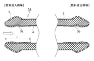
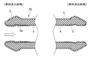
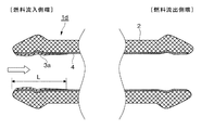
このような知見からなされた本発明の燃料圧送用配管の実施態様の例を図2から図5に示す。これらの図は、配管の燃料流入側端の断面の形状を示す模式断面図である。図2から図5において2は配管母材、3は配管外表面のZnめっき層またはZn基合金めっき層からなる外部防錆皮膜層、3a、3bは配管内面に設けられるZnめっき層またはZn基合金めっき層からなる防錆皮膜層、Lは配管内面の防錆皮膜層の配管先端からの被覆距離、4はNiめっき層、白抜き矢印は燃料の流れ方向を示すものである。
図2に示す燃料圧送配管1aは、配管外表面にZnめっき層またはZn基合金めっき層からなる外部防錆皮膜3、燃料流入側端の内面および燃料流出側端の内面にZnめっき層またはZn基合金めっき層からなる防錆皮膜層(3a、3b)を有する燃料圧送配管、図3の燃料圧送配管1bは、配管外表面にZnめっき層またはZn基合金めっき層からなる外部防錆皮膜3、燃料流入側端の内面のみにZnめっき層またはZn基合金めっき層からなる防錆皮膜層3aを有する燃料圧送配管、図4の燃料圧送配管1cは、燃料流入側端の内面および燃料流出側端の内面にのみZnめっき層またはZn基合金めっき層からなる防錆皮膜層(3a、3b)を有する燃料圧送配管、図5の燃料圧送配管1dは、燃料流入側端の内面にのみZnめっき層またはZn基合金めっき層からなる防錆皮膜層3aを有する燃料圧送配管を示している。
Examples of embodiments of the fuel pressure feeding pipe of the present invention made from such knowledge are shown in FIGS. These drawings are schematic cross-sectional views showing the cross-sectional shape of the fuel inflow side end of the pipe. 2 to 5, 2 is a pipe base material, 3 is an external anticorrosive film layer made of a Zn plating layer or Zn-base alloy plating layer on the outer surface of the pipe, and 3 a and 3 b are Zn plating layers or Zn bases provided on the inner surface of the pipe An anticorrosion film layer made of an alloy plating layer, L is a coating distance from the pipe tip of the anticorrosion film layer on the inner surface of the pipe, 4 is an Ni plating layer, and a white arrow indicates a fuel flow direction.
The
図2から図5の1aから1dで代表して示す本発明の燃料圧送配管は、Niめっき層4を設けた配管内面に配管先端、特に燃料流入側端(図1における高圧ポンプ20側端)から燃料の流れ方向(直噴レール中央方向)に向かって距離L(mm)の位置までZnめっき層またはZn基合金めっき層からなる防錆皮膜層3aをNiめっき層4上に設けた構造を採っている。さらに、燃料流出側端にも同様にZnめっき層またはZn基合金めっき層からなる防錆皮膜層3bを設けてあっても良い。
The fuel pumping pipe of the present invention, which is represented by 1a to 1d in FIGS. 2 to 5, has a pipe tip, particularly a fuel inflow side end (a
本発明は燃料圧送配管1の内面に、燃料流入側の配管端から適当な距離(本発明で規定する符号Lで示される距離)までNiめっき層4の表面にZnめっき層またはZn基合金めっき層からなる防錆皮膜層(3a、3b)を被覆することによって、水分、塩類、酸などの腐食性因子を多く含む腐食性燃料による配管腐食の防止を特徴としている。
In the present invention, a Zn plating layer or a Zn-based alloy plating is applied to the surface of the
その腐食に対する防止効果の詳細はまだ明らかでないが、以下のように考えられる。
内径が8mm位までの燃料圧送配管の管内面に設けられたZnめっき層またはZn基合金めっき層からなる防錆皮膜層より腐食性燃料に溶け出したZnイオンが、腐食性燃料中の腐食因子成分(塩類等)を中和して燃料の腐食性を抑制することにより、防錆皮膜層が被覆されている管内表面の一部分だけでなくNiめっき層だけの部位においても管素材の腐食を防ぐことができる。
この場合、腐食性燃料の通液入口(燃料流入側)となる配管端部にZnめっき層またはZn基合金めっき層からなる防錆皮膜層を施すことにより、腐食性燃料が必ず最初に防錆皮膜層に触れ、Znイオンが溶出して腐食因子が中和されることによって、より確実に管内表面のNiめっき層のみの部位の腐食を防ぐことができる。
Although the details of the prevention effect against corrosion are not yet clear, it is considered as follows.
Zn ions dissolved into corrosive fuel from a rust preventive coating layer consisting of a Zn plating layer or a Zn-based alloy plating layer provided on the inner surface of a fuel pumping pipe having an inner diameter of about 8 mm are corrosive factors in the corrosive fuel. By inhibiting the corrosiveness of the fuel by neutralizing the components (salts, etc.), corrosion of the pipe material is prevented not only at a part of the inner surface of the pipe covered with the anticorrosive coating layer but also at the site of only the Ni plating layer. be able to.
In this case, the corrosive fuel must be first rust-prevented by applying a rust-proof coating layer consisting of a Zn plating layer or Zn-based alloy plating layer to the pipe end that will be the corrosive fuel inlet (fuel inflow side). By touching the coating layer and elution of Zn ions to neutralize the corrosion factors, corrosion of only the Ni plating layer on the inner surface of the tube can be prevented more reliably.
また、防錆皮膜層が腐食性燃料に対して犠牲防食反応を起すことだけで、閉鎖的な管内においては腐食性燃料の腐食性が緩和されてしまう。そのため結果としてNiめっき層だけの部位においても管素材の腐食を防ぐことができる。この場合、腐食性燃料の通液入口となる配管端部に防錆皮膜層を設けることにより、腐食性燃料が必ず最初に防錆皮膜層に触れ、犠牲防食反応を起すため、より確実に管内表面のNiめっき層のみの部位の腐食を防ぐことができる。 Moreover, the corrosiveness of the corrosive fuel is alleviated only in the closed pipe by causing the sacrificial anticorrosive reaction to the corrosive fuel. Therefore, as a result, corrosion of the tube material can be prevented even in the portion having only the Ni plating layer. In this case, by providing a rust preventive coating layer at the end of the pipe that will be the inlet of the corrosive fuel, the corrosive fuel always touches the rust preventive coating layer first and causes a sacrificial anticorrosive reaction. Corrosion of only the Ni plating layer on the surface can be prevented.
次に、各要素の限定理由を説明する。
〔内面のZnめっき層またはZn基合金めっき層からなる防錆皮膜層〕
内面に設けられる防錆皮膜層としては、Znめっき層もしくはZn−Ni合金、Zn−Sn合金などのZn基合金めっき層が設けられる。
このZnめっき層あるいはZn基合金めっき層の形成は、管内面へ直接に電気めっきする方法、あるいは管外表面にZnめっき層を設けるような場合に、管外表面へのZnめっき層形成時に管内面へのZnめっき層の巻き込みによってZnめっき層を形成する方法などを用いることができるが、本発明に規定する配管内面に設けられる防錆皮膜層であるZnめっき層またはZn基合金めっき層の条件(被覆距離L)を満足する方法なら、どのような方法であっても何ら差支えない。
なお、燃料圧送配管内のガソリン燃料(腐食性燃料)に対する防錆皮膜層(Znめっき層、Zn基合金メッキ層)から溶出されるZnイオンの溶出量は1ppm未満であることが好ましい。Znイオンの溶出量が1ppm未満であれば、少なくとも内燃機関各所に各種弊害をもたらすことはないからである。但し、Znめっき層のめっき量が少なすぎても(Znイオンの溶出量が0.1ppm未満)、今度は防錆力(耐食性燃料を中和抑制する能力)が低下するため好ましくない。
Next, the reasons for limiting each element will be described.
[Anti-rust coating layer consisting of Zn plating layer or Zn-base alloy plating layer on the inner surface]
As the anticorrosive film layer provided on the inner surface, a Zn plating layer or a Zn-based alloy plating layer such as a Zn—Ni alloy or a Zn—Sn alloy is provided.
The formation of the Zn plating layer or the Zn-based alloy plating layer is performed by directly electroplating the inner surface of the tube, or when the Zn plating layer is provided on the outer surface of the tube. A method of forming a Zn plating layer by entraining the Zn plating layer on the surface can be used, but a Zn plating layer or a Zn-based alloy plating layer which is a rust preventive coating layer provided on the inner surface of the pipe defined in the present invention. Any method can be used as long as it satisfies the condition (covering distance L).
In addition, it is preferable that the elution amount of Zn ion eluted from the antirust coating layer (Zn plating layer, Zn base alloy plating layer) with respect to gasoline fuel (corrosive fuel) in the fuel pumping pipe is less than 1 ppm. This is because if the elution amount of Zn ions is less than 1 ppm, it will not cause various adverse effects at least in various parts of the internal combustion engine. However, if the Zn plating layer is too small (the Zn ion elution amount is less than 0.1 ppm), the rust preventive power (the ability to neutralize the corrosion-resistant fuel) is reduced, which is not preferable.
図6に配管内面のZnめっき層またはZn基合金めっき層からなる防錆皮膜層の様子を示す。図6は本発明の燃料圧送配管の燃料流入側端の部分拡大断面図である。
配管内面の防錆皮膜層3aの配管先端からの被覆距離Lは配管内径がDmmである時に、D〜6Dmmの位置まで防錆皮膜層3aが設けられていることが望ましい。
また図6に示すように、この防錆皮膜層3aにおける層厚みtZnは、0.1〜8μmの厚みで設けられていることが望ましい。
なお、燃料流出側端における防錆皮膜層3bについても同様の条件で設けられる。
FIG. 6 shows a state of the rust-preventing film layer composed of a Zn plating layer or a Zn-based alloy plating layer on the inner surface of the pipe. FIG. 6 is a partially enlarged cross-sectional view of the fuel inflow side end of the fuel pumping pipe of the present invention.
The coating distance L from the pipe tip of the
Further, as shown in FIG. 6, the layer thickness t Zn in the rust preventing
In addition, it is provided on the same conditions also about the
[Znめっき層またはZn基合金めっき層からなる外部防錆皮膜]
燃料圧送配管の一部または全部の外表面に設けられる外部防錆皮膜層3は、外部の腐食因子から配管の腐食を防ぐ役割を果たすもので、3〜25μm、望ましくは5〜13μmの厚みで電気めっき法などの方法で設けられる。なお、外表面に外部防錆皮膜層3を設ける仕様の燃料圧送配管の場合には、外表面の外部防錆皮膜層3を設ける際に、同時に所定の形態の内面を被覆する防錆皮膜層(3a、3b)を設けても良い。
[External rust preventive film consisting of Zn plating layer or Zn-base alloy plating layer]
The external rust
〔Niめっき層〕
Niめっき層4は燃料圧送配管の配管母材2の内面と直接に接する位置に例えば電気めっき法や無電解めっき(化学めっき)などの方法で設けられることで、配管母材2の内面を覆って腐食性燃料と配管母材との接触を断つ、バリアーの役目を果たすものである。なお、Niめっき層を形成後に、拡散層を生成して配管母材との密着性を高めるために適宜熱処理を行っても良い。
その厚みは、1〜15μmが望ましく(Niめっき層の拡散層がある場合には該Niめっき層の拡散層も含めて、1〜15μm)、3〜9μmがより望ましい(Niめっき層の拡散層がある場合には該Niめっき層の拡散層も含めて、3〜9μm)。1μm未満では腐食性燃料からの配管母材への腐食攻撃に対するバリアー機能が十分機能しないためである。また9μmを超えると効果の度合いが緩やかになり、15μmを超えては、製造コストの上昇に見合う効果の向上が見られないばかりか、配管の塑性加工(例えば曲げ加工など)を行った際にめっき皮膜に亀裂(ワレ)が発生しやすくなって、むしろバリアー機能が低下する問題が生じるためである。また、Niめっきが外面(全体)にもつき回っても良い。
[Ni plating layer]
The
The thickness is preferably 1 to 15 μm (if the Ni plating layer has a diffusion layer, 1 to 15 μm including the diffusion layer of the Ni plating layer), and more preferably 3 to 9 μm (the diffusion layer of the Ni plating layer). 3 to 9 μm including the diffusion layer of the Ni plating layer. If the thickness is less than 1 μm, the barrier function against corrosion attack on the pipe base material from the corrosive fuel does not function sufficiently. Moreover, when the thickness exceeds 9 μm, the degree of the effect becomes moderate, and when it exceeds 15 μm, not only the improvement of the effect corresponding to the increase in manufacturing cost is not seen, but also when plastic processing (for example, bending processing) of the pipe is performed. This is because cracks (breaks) are likely to occur in the plating film, and rather the barrier function deteriorates. Moreover, Ni plating may also circulate on the outer surface (whole).
〔配管母材〕
本発明の燃料圧送配管に用いられる配管母材2には、圧送される燃料の高圧力に耐えうる耐圧性を有するスチール製のシームレス管が好適である。
[Piping base material]
For the
〔腐食性燃料〕
本発明に係る燃料圧送配管は、日本で一般に市販されている「高品質の燃料」に対して用いられるよりも、「腐食性燃料」に対して用いられた場合に、より有効な作用効果を得ることが出来る。
即ち、本発明の燃料圧送配管は、腐食性燃料となりやすいバイオ由来のアルコール混合燃料に含まれるアルコールがバイオ由来、すなわち化学合成であることによって、不純物の「塩素イオン」や「水分」などが混入した燃料を使用した場合、あるいは長期滞留に伴い酸化が進み、腐食因子となる蟻酸、酢酸などの酸が生じている劣化ガソリンを含むガソリンを使用する場合、劣悪な環境下で製造、供給される腐食性因子を多く含むガソリンなどに対して特に有効である。
より詳しくは、有機酸(蟻酸および酢酸)100〜1000ppm或いはそれ以上、水分1〜10%或いはそれ以上、塩素1〜100ppm或いはそれ以上を含むような腐食性に富む腐食性燃料に対して顕著な効果を示すものである。
[Corrosive fuel]
The fuel pumping pipe according to the present invention has a more effective operation effect when used for “corrosive fuel” than used for “high quality fuel” generally marketed in Japan. Can be obtained.
In other words, the fuel pressure delivery pipe of the present invention is mixed with impurities such as “chlorine ions” and “moisture” because the alcohol contained in the bio-derived alcohol mixed fuel, which is likely to become corrosive fuel, is bio-derived, that is, chemically synthesized. Produced or supplied in a poor environment when used fuel is used, or when gasoline containing deteriorated gasoline in which acid such as formic acid or acetic acid, which becomes a corrosive factor, has been oxidized due to long-term residence, is generated. This is particularly effective for gasoline that contains many corrosive factors.
More specifically, it is prominent for highly corrosive corrosive fuels containing 100 to 1000 ppm or more of organic acids (formic acid and acetic acid), 1 to 10% or more of moisture, and 1 to 100 ppm or more of chlorine. It shows the effect.
以下、実施例を用いて本発明を詳細する。
実施例では、配管内面に施した防錆皮膜層の示す効果について、腐食性燃料に対する腐食試験を行い、腐食状況(耐食性)を目視並びに顕微鏡で観察して判定した。また、Znめっき層またはZn基合金めっき層からなる防錆皮膜層からのZn溶出の度合いを判定する目的で腐食試験後の試験液を成分分析して、その溶出量を測定した。
さらに、配管内のめっき層の密着性をJASO−M−101に準拠した曲げ試験を行い評価した。剥がれ、ワレを生じた場合を「×」とした。
Hereinafter, the present invention will be described in detail using examples.
In the examples, the effect of the anticorrosive film layer applied to the inner surface of the pipe was determined by conducting a corrosion test on a corrosive fuel and observing the corrosion state (corrosion resistance) visually and with a microscope. In addition, for the purpose of determining the degree of Zn elution from a rust-preventing coating layer comprising a Zn plating layer or a Zn-based alloy plating layer, the test solution after the corrosion test was subjected to component analysis and the elution amount was measured.
Further, the adhesion of the plating layer in the pipe was evaluated by performing a bending test in accordance with JASO-M-101. The case where peeling and cracking occurred was defined as “x”.
[内面の防錆皮膜層および外部防錆皮膜層の形成法]
1.Znめっき層
市販のジンケート浴(JASCO社製)を用い、電流密度3A/dm2で管外表面に電着めっきを施すと同時に、管内面に対してはスチール製ワイヤの疑似陽極を併用して所望の被覆距離(L)の範囲に電着した。なお、外表面と内面で異なる種類の皮膜層を設ける場合には、個々にめっきを施すが、それぞれに影響を与えないようにマスキングを施して行うと良い。
[Method of forming inner and outer antirust coating layers]
1. Zn plating layer Using a commercially available zincate bath (manufactured by JASCO), the outer surface of the tube is electrodeposited at a current density of 3 A / dm 2 and at the same time, a steel wire pseudo-anode is used in combination with the inner surface of the tube. Electrodeposition was performed in the range of the desired coating distance (L). In the case where different types of coating layers are provided on the outer surface and the inner surface, plating is performed individually, but it is preferable to perform masking so as not to affect each of them.
2.Zn基合金めっき層/Zn−Ni合金めっき層
市販のアルカリ浴(JASCO社製)を用い、電流密度5A/dm2で管外表面に電着めっきを施すと同時に、管内面に対してはニッケル製ワイヤの疑似陽極を併用して所望の被覆距離(L)の範囲に電着した。
2. Zn-base alloy plating layer / Zn-Ni alloy plating layer Using a commercially available alkaline bath (manufactured by JASCO), electrodeposition plating was performed on the outer surface of the tube at a current density of 5 A / dm 2 and at the same time nickel was applied to the inner surface of the tube Electrodeposition was performed in the range of the desired coating distance (L) in combination with a pseudo-anode made of wire.
3.Zn基合金めっき層/Sn−Zn合金めっき層
市販の中性浴(ディップソール社製)を用い、電流密度2A/dm2で管外表面に電着めっきを施すと同時に、管内面に対してはステンレス製ワイヤの疑似陽極を併用して所望の被覆距離(L)の範囲に電着した。
3. Zn-based alloy plating layer / Sn—Zn alloy plating layer Using a commercially available neutral bath (manufactured by Dipsol), electrodeposition plating was performed on the outer surface of the tube at a current density of 2 A / dm 2 , and at the same time the inner surface of the tube Was electrodeposited in the range of the desired coating distance (L) in combination with a stainless steel pseudo-anode.
[Niめっき層の形成法]
1.電気Niめっき
市販の酸性浴(ワット浴)及びニッケル製ワイヤの陽極を用い、電流密度3A/dm2で管内面全域に電着めっきを施した。
2.無電解NiPめっき(実施例3のみ使用)
市販の酸性浴(カニゼンめっき)を用い、浴温:90〜95℃で管内面全域に対して化学めっきを施した。
[Method of forming Ni plating layer]
1. Electro Ni plating Electrodeposition plating was applied to the entire inner surface of the tube at a current density of 3 A / dm 2 using a commercially available acid bath (Watt bath) and a nickel wire anode.
2. Electroless NiP plating (used only in Example 3)
Using a commercially available acid bath (Kanizen plating), chemical plating was applied to the entire inner surface of the tube at a bath temperature of 90 to 95 ° C.
〔腐食試験細目〕
・試験液;腐食性燃料
・20%アルコール混合燃料(ガソリン)
有機酸(蟻酸および酢酸)500ppm、水分5%、塩素10ppmを含む
・試験方法
試験燃料を管内に封入して下記条件に放置した時の管内の腐食状況を確認。さらに、封入してあった試験燃料を採取して、成分分析(水分抽出後に遊離Znイオン濃度を測定)を実施。
・試験温度:100℃
・試験時間:1000時間(試験液は100時間ごとに新しい試験液に交換)
・腐食評価:錆の有無を目視観察。
[Details of corrosion test]
・ Test liquid; corrosive fuel ・ 20% alcohol mixed fuel (gasoline)
Contains 500 ppm organic acid (formic acid and acetic acid), 5% moisture, 10 ppm chlorine. ・ Test method Check the corrosion status in the tube when the test fuel is sealed in the tube and left under the following conditions. In addition, the encapsulated test fuel was collected and subjected to component analysis (measured free Zn ion concentration after moisture extraction).
Test temperature: 100 ° C
Test time: 1000 hours (The test solution is replaced with a new test solution every 100 hours)
・ Corrosion evaluation: Visual observation of rust.
図2に示す構造の本発明の燃料圧送配管1aにおいて、配管母材2に内径5mm(D=5mm)の高圧用スチール製管材を用いて、その内面全体に厚み10μmのNiめっきを施してNiめっき層4を形成し、ついで管端からの防錆皮膜層をZnめっき層とし、その被覆距離Lを10mm(L=2D=10mm)とし、この位置まで0.1〜8μmの厚みでZnめっきを施して防錆皮膜層3a、3bを形成し、圧送燃料配管の供試材を作製した。この供試材を用いて腐食性燃料に対する腐食試験を行った。その結果を表1に示す。
In the
図2に示す構造の本発明の燃料圧送配管1aにおいて、配管母材2に内径8mm(D=8mm)の高圧用スチール製管材を用いて、その内面全体に厚み10μmのNiめっきを施してNiめっき層4を形成し、ついで管端からの防錆皮膜層をZn−Ni層とし、その被覆距離Lを24mm(L=3D=24mm)とし、この位置まで0.1〜8μmの厚みでZn−Ni合金めっきを施して、防錆皮膜層3a、3bを形成し、圧送燃料配管の供試材を作製した。この供試材を用いて試験液に腐食性燃料に対する腐食試験を行った。その結果を表1に示す。
In the
図2に示す構造の本発明の燃料圧送配管1aにおいて、配管母材2に内径3mm(D=3mm)の高圧用スチール製管材を用いて、無電解NiPめっきにより厚み5μmのNiめっき層を設け、内面の防錆皮膜層をSn−Zn合金めっき層とし、その被覆距離Lを9mm(L=3D=9mm)とし、この位置まで0.1〜8μmの厚みでSn−Zn合金めっきを施して防錆皮膜層3a、3bを形成し、圧送燃料配管の供試材を作製した。この供試材を用いて試験液に腐食性燃料に対する腐食試験を行った。その結果を表1に示す。
In the
図2に示す構造の本発明の燃料圧送配管1aにおいて、配管母材2に内径8mm(D=8mm)の高圧用スチール製管材を用いて、その内面全体に厚み15μmのNiめっきを施してNiめっき層4を形成し、ついで管端からの防錆皮膜層をZnめっき層とし、その被覆距離Lを8mm(L=1D=8mm)とし、この位置まで0.1〜8μmの厚みでZnめっきを施して防錆皮膜層3a、3bを形成し、圧送燃料配管の供試材を作製した。この供試材を用いて試験液に腐食性燃料に対する腐食試験を行った。その結果を表1に示す。
In the
図2に示す構造の本発明の燃料圧送配管1aにおいて、配管母材2に内径5mm(D=5mm)の高圧用スチール製管材を用いて、その内面全体に厚み5μmのNiめっきを施してNiめっき層4を形成し、ついで管端からの防錆皮膜層をZnめっき層とし、その被覆距離Lを30mm(L=6D=30mm)とし、この位置まで0.1〜8μmの厚みでZnめっきを施して防錆皮膜層3a、3bを形成し、圧送燃料配管の供試材を作製した。この供試材を用いて試験液に腐食性燃料に対する腐食試験を行った。その結果を表1に示す。
In the
(比較例1)
図2に示す構造の本発明の燃料圧送配管1aにおいて、配管母材2に内径8mm(D=8mm)の高圧用スチール製管材を用いて、その内面全体に厚み5μmのNiめっきを施してNiめっき層4を形成し、ついで管端からの防錆皮膜層をZnめっき層とし、その被覆距離Lを80mm(L=10D=80mm)とし、この位置まで0.1〜8μmの厚みでZnめっきを施して、防錆皮膜層3a、3bを形成し、圧送燃料配管の供試材を作製した。この供試材を用いて試験液に腐食性燃料に対する腐食試験を行った。その結果を表1に示す。
(Comparative Example 1)
In the
(比較例2)
図2に示す構造の本発明の燃料圧送配管1aにおいて、配管母材2に内径3mm(D=3mm)の高圧用スチール製管材を用いて、その内面全体に厚み20μmのNiめっきを施してNiめっき層4を形成し、ついで管端からの防錆皮膜層をZn−Ni合金めっき層とし、その被覆距離Lを12mm(L=4D=12mm)とし、この位置まで0.1〜8μmの厚みでZn−Ni合金めっきを施して防錆皮膜層3a、3bを形成し、圧送燃料配管の供試材を作製した。この供試材を用いて試験液に腐食性燃料に対する腐食試験を行った。その結果を表1に示す。
(Comparative Example 2)
In the
(比較例3)
図2に示す構造の本発明の燃料圧送配管1aにおいて、配管母材2に内径8mm(D=8mm)の高圧用スチール製管材を用いて、その内面全体に厚み5μmのNiめっきを施してNiめっき層4を形成し、ついで管端からの防錆皮膜層をSn−Zn合金めっき層とし、その被覆距離Lを4mm(L=0.5D=4mm)とし、この位置まで0.1〜8μmの厚みでSn−Zn合金めっきを施して防錆皮膜層3a、3bを形成し、圧送燃料配管の供試材を作製した。この供試材を用いて試験液に腐食性燃料に対する腐食試験を行った。その結果を表1に示す。
(Comparative Example 3)
In the
(比較例4)
図7に示す構造の従来の燃料圧送配管50において、配管母材2に高圧用スチール製管材を用いて、その内面全体に厚み5μmのNiめっきを施してNiめっき層4を形成して、圧送燃料配管の供試材を作製した。この供試材を用いて試験液として腐食性燃料に対する腐食試験を行った。その結果を表1に示す。
(Comparative Example 4)
In the conventional
(比較例5)
配管母材にSUS304製管材を用いた圧送燃料配管の供試材を作製した。この供試材を用いて試験液に腐食性燃料に対する腐食試験を行った。その結果を表1に示す。
(Comparative Example 5)
A test material for a pressure-feed fuel pipe using a pipe material made of SUS304 as a pipe base material was prepared. A corrosion test for a corrosive fuel was performed on the test solution using the sample material. The results are shown in Table 1.

表1から明らかなように、Niめっき厚、防錆皮膜層の被覆距離共に、本発明範囲内にある実施例1から5では、密着性、耐食性共に良好で、試験燃料内のZnイオンの溶出量も1ppmを下回っているのがわかる。 As is clear from Table 1, in Examples 1 to 5 where the Ni plating thickness and the coating distance of the anticorrosive coating layer are within the scope of the present invention, both adhesion and corrosion resistance are good, and Zn ions are eluted in the test fuel. It can be seen that the amount is below 1 ppm.
一方、防錆皮膜層の被覆距離が長すぎる比較例1では、Znイオンの溶出量が2.8ppmと増えており、内燃機関の各所に弊害を引き起こしやすくなると考えられる。他方、防錆皮膜層の被覆距離が短い比較例3では、Znイオンの溶出量が少ないことから耐食性が劣化していることがわかる。
また、Niめっき層の厚みの値が大きい比較例2では、密着性に劣ってしまうことがわかる。さらに、防錆皮膜層を有しない比較例4、およびSUS304製管材を用いた圧送燃料配管の比較例5では、耐食性が劣っている。
On the other hand, in Comparative Example 1 in which the coating distance of the rust preventive coating layer is too long, the elution amount of Zn ions is increased to 2.8 ppm, which is considered to easily cause adverse effects in various parts of the internal combustion engine. On the other hand, in Comparative Example 3 in which the coating distance of the rust preventive film layer is short, it can be seen that the corrosion resistance is deteriorated because the elution amount of Zn ions is small.
Moreover, it turns out that it is inferior to adhesiveness in the comparative example 2 with a large value of the thickness of Ni plating layer. Furthermore, in Comparative Example 4 that does not have a rust preventive film layer and Comparative Example 5 of a pressure-feed fuel pipe using a SUS304 pipe material, the corrosion resistance is inferior.
1、1a、1b、1c、1d 圧送燃料配管
2 配管母材
3 配管外表面の外部防錆皮膜層
3a 燃料流入側端の配管内面被覆防錆皮膜層
3b 燃料流出側端の配管内面被覆防錆皮膜層
4 Niめっき層
10 燃料タンク
20 高圧ポンプ
30 直噴レール
31 インジェクター
50 従来圧送燃料配管
L 防錆皮膜層の被覆距離
DESCRIPTION OF
Claims (5)
Priority Applications (9)
| Application Number | Priority Date | Filing Date | Title |
|---|---|---|---|
| JP2010165881A JP5773515B2 (en) | 2010-07-23 | 2010-07-23 | Steel fuel pumping pipe |
| CN201180032169.XA CN103026046B (en) | 2010-07-23 | 2011-07-05 | The fuel pressure of steel is provided and delivered and is managed |
| RU2013108114/06A RU2550297C2 (en) | 2010-07-23 | 2011-07-05 | Steel fuel fed line |
| PCT/JP2011/065325 WO2012011384A1 (en) | 2010-07-23 | 2011-07-05 | Steel fuel conveying pipe |
| MX2013000349A MX2013000349A (en) | 2010-07-23 | 2011-07-05 | Steel fuel conveying pipe. |
| EP11809558.7A EP2597297B1 (en) | 2010-07-23 | 2011-07-05 | Steel fuel conveying pipe |
| US13/805,437 US9012031B2 (en) | 2010-07-23 | 2011-07-05 | Steel fuel conveying pipe |
| BR112013001679A BR112013001679A2 (en) | 2010-07-23 | 2011-07-05 | fuel transport steel pipe |
| KR1020137001758A KR101490639B1 (en) | 2010-07-23 | 2011-07-05 | Steel fuel conveying pipe |
Applications Claiming Priority (1)
| Application Number | Priority Date | Filing Date | Title |
|---|---|---|---|
| JP2010165881A JP5773515B2 (en) | 2010-07-23 | 2010-07-23 | Steel fuel pumping pipe |
Publications (3)
| Publication Number | Publication Date |
|---|---|
| JP2012026357A JP2012026357A (en) | 2012-02-09 |
| JP2012026357A5 JP2012026357A5 (en) | 2013-08-29 |
| JP5773515B2 true JP5773515B2 (en) | 2015-09-02 |
Family
ID=45496811
Family Applications (1)
| Application Number | Title | Priority Date | Filing Date |
|---|---|---|---|
| JP2010165881A Active JP5773515B2 (en) | 2010-07-23 | 2010-07-23 | Steel fuel pumping pipe |
Country Status (9)
| Country | Link |
|---|---|
| US (1) | US9012031B2 (en) |
| EP (1) | EP2597297B1 (en) |
| JP (1) | JP5773515B2 (en) |
| KR (1) | KR101490639B1 (en) |
| CN (1) | CN103026046B (en) |
| BR (1) | BR112013001679A2 (en) |
| MX (1) | MX2013000349A (en) |
| RU (1) | RU2550297C2 (en) |
| WO (1) | WO2012011384A1 (en) |
Families Citing this family (8)
| Publication number | Priority date | Publication date | Assignee | Title |
|---|---|---|---|---|
| US9700928B2 (en) * | 2010-08-06 | 2017-07-11 | Toyo Kohan Co., Ltd. | Steel plate for producing pipe highly resistant to fuel vapor corrosion, pipe using same and method for producing pipe |
| JP6245687B2 (en) | 2013-09-10 | 2017-12-13 | 臼井国際産業株式会社 | Steel fuel pumping pipe |
| JP2016037928A (en) * | 2014-08-08 | 2016-03-22 | 臼井国際産業株式会社 | Terminal seal structure of fuel rail for gasoline direct-injection engine |
| JP6713755B2 (en) * | 2015-11-18 | 2020-06-24 | 三桜工業株式会社 | Fuel distribution pipe |
| TWI585079B (en) * | 2015-12-30 | 2017-06-01 | 奇美實業股份有限公司 | Urethane compound |
| RU2649218C1 (en) * | 2016-11-18 | 2018-03-30 | Федеральное государственное бюджетное учреждение науки Институт ядерной физики им. Г.И. Будкера Сибирского отделения РАН (ИЯФ СО РАН) | Method for forming anti-corrosive coating on articles from low-carbon steel |
| JP7080583B2 (en) | 2017-02-28 | 2022-06-06 | 臼井国際産業株式会社 | Manufacturing method of steel fuel pumping pipe |
| DE102018220570A1 (en) | 2018-11-29 | 2020-06-04 | Robert Bosch Gmbh | Compact exhaust aftertreatment system |
Family Cites Families (20)
| Publication number | Priority date | Publication date | Assignee | Title |
|---|---|---|---|---|
| JPS61222736A (en) * | 1985-03-28 | 1986-10-03 | 臼井国際産業株式会社 | Corrosion-resistant coated steel pipe and coating forming method thereof |
| GB2222785B (en) * | 1988-09-17 | 1992-02-12 | Usui Kokusai Sangyo Kk | Multi-layered pipe coating |
| US5246786A (en) * | 1988-10-29 | 1993-09-21 | Usui Kokusai Sangyo Kaisha Ltd. | Steel product with heat-resistant, corrosion-resistant plating layers |
| JP2750710B2 (en) | 1988-10-29 | 1998-05-13 | 臼井国際産業株式会社 | Heat-resistant and corrosion-resistant steel with multi-layer plating |
| US5422192A (en) * | 1989-10-06 | 1995-06-06 | Usui Kokusai Sangyo Kaisha Ltd. | Steel product with heat-resistant, corrosion-resistant plating layers |
| US5277228A (en) | 1990-11-02 | 1994-01-11 | Usui Kokusai Sangyo Kaisha Limited | Welded pipe with excellent corrosion resistance inner surface |
| BE1005554A3 (en) * | 1991-12-10 | 1993-10-26 | Bundy Internat Ltd | Method of manufacturing a tube wall multiple. |
| JP3403263B2 (en) * | 1994-11-14 | 2003-05-06 | 臼井国際産業株式会社 | Heat-resistant and corrosion-resistant plated steel with excellent workability and corrosion resistance uniformity |
| RU2105921C1 (en) | 1996-04-18 | 1998-02-27 | Виктор Михайлович Рябов | Tube provided with internal coat and method of its manufacture |
| JP3885910B2 (en) * | 1997-10-09 | 2007-02-28 | 臼井国際産業株式会社 | Fuel delivery pipe and manufacturing method thereof |
| JP2954555B2 (en) * | 1997-11-06 | 1999-09-27 | 臼井国際産業株式会社 | Heat and corrosion resistant multi-layer plated steel |
| GB2345918B (en) * | 1999-01-25 | 2003-03-12 | San O Ind Co | Steel product with plating layers |
| JP2002054534A (en) | 2000-08-10 | 2002-02-20 | Nissan Motor Co Ltd | Fuel injection device for engine |
| JP2003034877A (en) | 2001-07-23 | 2003-02-07 | Sanoh Industrial Co Ltd | Method for manufacturing pipe molded article, and pipe molded article |
| JP2004052093A (en) * | 2002-07-24 | 2004-02-19 | Sanoh Industrial Co Ltd | Multilayer plated automobile fuel piping part |
| JP4225404B2 (en) * | 2002-11-08 | 2009-02-18 | 臼井国際産業株式会社 | Fin tubes for automotive fuel coolers with high heat and corrosion resistant coatings |
| JP4391101B2 (en) | 2003-02-25 | 2009-12-24 | 三桜工業株式会社 | Continuous plating equipment |
| JP2006152852A (en) * | 2004-11-26 | 2006-06-15 | Toyota Motor Corp | Fuel line of internal combustion engine |
| US7028668B1 (en) | 2004-12-21 | 2006-04-18 | Robert Bosch Gmbh | Self-damping fuel rail |
| JP5510992B2 (en) | 2008-06-30 | 2014-06-04 | 臼井国際産業株式会社 | Fuel rail for high pressure direct injection internal combustion engine and method for manufacturing the same |
-
2010
- 2010-07-23 JP JP2010165881A patent/JP5773515B2/en active Active
-
2011
- 2011-07-05 MX MX2013000349A patent/MX2013000349A/en active IP Right Grant
- 2011-07-05 BR BR112013001679A patent/BR112013001679A2/en active Search and Examination
- 2011-07-05 CN CN201180032169.XA patent/CN103026046B/en active Active
- 2011-07-05 US US13/805,437 patent/US9012031B2/en active Active
- 2011-07-05 WO PCT/JP2011/065325 patent/WO2012011384A1/en active Application Filing
- 2011-07-05 KR KR1020137001758A patent/KR101490639B1/en active IP Right Grant
- 2011-07-05 RU RU2013108114/06A patent/RU2550297C2/en active
- 2011-07-05 EP EP11809558.7A patent/EP2597297B1/en active Active
Also Published As
| Publication number | Publication date |
|---|---|
| RU2013108114A (en) | 2014-08-27 |
| US20130098496A1 (en) | 2013-04-25 |
| BR112013001679A2 (en) | 2016-05-24 |
| MX2013000349A (en) | 2013-03-08 |
| CN103026046B (en) | 2015-11-25 |
| KR20130031905A (en) | 2013-03-29 |
| JP2012026357A (en) | 2012-02-09 |
| EP2597297A4 (en) | 2015-12-30 |
| RU2550297C2 (en) | 2015-05-10 |
| WO2012011384A1 (en) | 2012-01-26 |
| KR101490639B1 (en) | 2015-02-05 |
| CN103026046A (en) | 2013-04-03 |
| EP2597297B1 (en) | 2019-09-04 |
| EP2597297A1 (en) | 2013-05-29 |
| US9012031B2 (en) | 2015-04-21 |
Similar Documents
| Publication | Publication Date | Title |
|---|---|---|
| JP5773515B2 (en) | Steel fuel pumping pipe | |
| JP6245687B2 (en) | Steel fuel pumping pipe | |
| CN102959136B (en) | Steel plate for container and manufacture method thereof | |
| JP2009179848A (en) | Steel sheet for container and method of manufacturing the same | |
| CN107531017A (en) | Layered product and its manufacture method with corrosion resistant film | |
| CN107208277B (en) | Fuel steel plate for tanks | |
| CN102220133A (en) | Stripping solution of titanium carbide and/or titanium nitride film and stripping method | |
| JP2016114054A (en) | Gas exchange valve | |
| CN107366010A (en) | A kind of stainless steel pipes and device context highly corrosion resistant processing method | |
| JP5826735B2 (en) | Zinc-nickel alloy plating solution and zinc-nickel alloy plating method | |
| JP5971431B2 (en) | Plated steel sheet | |
| EP2871263B1 (en) | Pipe having heat-resistant corrosion-resistant plating layer that has excellent processability | |
| JP5550206B2 (en) | Zinc-nickel alloy plating solution and zinc-nickel alloy plating method | |
| JP3859941B2 (en) | Automotive fuel tank with excellent corrosion resistance | |
| CN105525317A (en) | Three-layer nickel plating process for battery steel shell and battery steel shell manufactured by process | |
| JP6886676B2 (en) | Fuel refueling pipe | |
| JPS6233795A (en) | Ni-fe alloy plated steel sheet for fuel vessel | |
| JP2001026899A (en) | Steel plate for highly corrosion resistant fuel tank and its production | |
| JP2957351B2 (en) | Alcohol or alcohol-containing fuel container steel plate | |
| CN203491389U (en) | Welding structure of electrode insertion sheet and enamelled wire of electric fuel pump | |
| CN114182240A (en) | Hydrogen blocking process for inner wall of hydrogen storage well of hydrogen storage container | |
| CN103521938A (en) | Welding technology for electrode inserting sheet and enameled wire of electric fuel pump | |
| JPH01176092A (en) | Surface treated steel sheet for alcohol-base fuel tank | |
| JPS6233794A (en) | Ni-cu alloy plated steel sheet for fuel vessel |
Legal Events
| Date | Code | Title | Description |
|---|---|---|---|
| A521 | Written amendment |
Free format text: JAPANESE INTERMEDIATE CODE: A523 Effective date: 20130711 |
|
| A621 | Written request for application examination |
Free format text: JAPANESE INTERMEDIATE CODE: A621 Effective date: 20130711 |
|
| A131 | Notification of reasons for refusal |
Free format text: JAPANESE INTERMEDIATE CODE: A131 Effective date: 20140702 |
|
| A02 | Decision of refusal |
Free format text: JAPANESE INTERMEDIATE CODE: A02 Effective date: 20150226 |
|
| A521 | Written amendment |
Free format text: JAPANESE INTERMEDIATE CODE: A523 Effective date: 20150522 |
|
| A911 | Transfer to examiner for re-examination before appeal (zenchi) |
Free format text: JAPANESE INTERMEDIATE CODE: A911 Effective date: 20150608 |
|
| TRDD | Decision of grant or rejection written | ||
| A01 | Written decision to grant a patent or to grant a registration (utility model) |
Free format text: JAPANESE INTERMEDIATE CODE: A01 Effective date: 20150625 |
|
| A61 | First payment of annual fees (during grant procedure) |
Free format text: JAPANESE INTERMEDIATE CODE: A61 Effective date: 20150629 |
|
| R150 | Certificate of patent or registration of utility model |
Ref document number: 5773515 Country of ref document: JP Free format text: JAPANESE INTERMEDIATE CODE: R150 |