JP4478099B2 - Air conditioner - Google Patents
Air conditioner Download PDFInfo
- Publication number
- JP4478099B2 JP4478099B2 JP2005339622A JP2005339622A JP4478099B2 JP 4478099 B2 JP4478099 B2 JP 4478099B2 JP 2005339622 A JP2005339622 A JP 2005339622A JP 2005339622 A JP2005339622 A JP 2005339622A JP 4478099 B2 JP4478099 B2 JP 4478099B2
- Authority
- JP
- Japan
- Prior art keywords
- area
- indoor unit
- control flap
- temperature
- floor
- Prior art date
- Legal status (The legal status is an assumption and is not a legal conclusion. Google has not performed a legal analysis and makes no representation as to the accuracy of the status listed.)
- Active
Links
Images


Landscapes
- Air Conditioning Control Device (AREA)
Description
この発明は、リモコンにより気流を送るエリアを指定し、室内機がそのエリアに向かって気流を送り、床温度センサーによりそのエリアの温度ムラを検出して、温度ムラを解消する空気調和機に関するものである。 The present invention relates to an air conditioner that designates an area to send airflow with a remote controller, an indoor unit sends airflow toward the area, detects temperature unevenness in the area with a floor temperature sensor, and eliminates temperature unevenness. It is.
室内に温度ムラがあって、しかも複数の人がいても負荷に応じた能力の分配制御をして、空調の快適性を向上させる空気調和機が提案されている(例えば、特許文献1参照)。 There has been proposed an air conditioner that improves the comfort of air conditioning by performing distribution control of the ability according to the load even when there are temperature irregularities in the room and there are a plurality of people (for example, see Patent Document 1). .
また、赤外線センサーを用いて、人体の存在方向と出力強度から距離を検知する位置検出手段を設け、人の存在位置に応じて風向及び風速を変更する空気調和機が提案されている(例えば、特許文献2参照)。 In addition, there has been proposed an air conditioner that uses an infrared sensor to provide a position detection unit that detects a distance from the presence direction of the human body and the output intensity, and changes the wind direction and the wind speed according to the position of the person (for example, Patent Document 2).
さらに、赤外線センサーを用いて、予め部屋の用途、月、曜日、時刻等の情報を入力する空気調和機が提案されている(例えば、特許文献3参照)。
従来の空気調和機は、床温度検出手段と人検出手段からの信号を受けて、本体から吹出される風向、風量、吹出し温度等の能力を人位置に応じて分配するので、例えば、夏場や冬に人が外から帰宅したときのように、床と人の温度差が少ないときには人を検知しにくく、気流を吹出すエリアが不明確になり、結局部屋全体を空調することになり、省エネ運転ができない。 The conventional air conditioner receives signals from the floor temperature detection means and the person detection means and distributes the capabilities of the wind direction, the air volume, the blowout temperature, etc. blown from the main body according to the person position. When the temperature difference between the floor and the person is small, such as when a person comes home from outside in winter, it is difficult to detect the person, the area where the air current is blown out becomes unclear, and the entire room is air-conditioned, which saves energy. I can't drive.
この発明は、上記のような課題を解決するためになされたもので、ユーザの要求に対応した快適な空調と省エネを実現できる空気調和機を提供することを目的とする。 This invention was made in order to solve the above problems, and it aims at providing the air conditioner which can implement | achieve the comfortable air conditioning and energy saving corresponding to a user's request | requirement.
この発明に係る空気調和機は、室内機と、この室内機に設けられ、部屋の床温度を検出する可動式の床温度センサーと、室内機の吹出し口に設けられ、一枚の又は左右に分割された上下制御フラップと、室内機の吹出し口に設けられ、左右に分割された左右制御フラップと、ユーザが気流を送るエリアを指定するエリア指定操作部を有するリモコンとを備え、このリモコンからエリア指定の信号が送信された場合、室内機は、その指定エリアに向けて気流が送られるように、風向、風速の初期値を設定し運転を行い、床温度センサーにより指定エリアの温度ムラを検出し、温度ムラがしきい値を超えた場合、風向、風速の補正を行うことを特徴とする。 An air conditioner according to the present invention is provided in an indoor unit, a movable floor temperature sensor that detects a floor temperature of a room, and a blowout port of the indoor unit. From the remote control, which is provided with a divided vertical control flap, a left and right control flap provided at the outlet of the indoor unit and divided into left and right, and a remote control having an area designating operation unit for designating an area where the user sends airflow When an area designation signal is sent, the indoor unit sets the initial values of the wind direction and wind speed so that the airflow is sent toward the designated area, operates, and the floor temperature sensor eliminates temperature unevenness in the designated area. If the temperature unevenness is detected and exceeds a threshold value, the wind direction and the wind speed are corrected.
この発明に係る空気調和機は、上記構成により、ユーザの要求に対応した快適な空調と省エネを実現できる。 With the above configuration, the air conditioner according to the present invention can realize comfortable air conditioning and energy saving corresponding to a user's request.
実施の形態1.
図1乃至図20は実施の形態1を示す図で、図1は空気調和機の室内機1の断面図、図2は上下制御フラップを除き左右制御フラップを示す室内機1の正面図(a)と断面図(b)、図3は左右制御フラップの動作を説明する室内機1の正面図、図4は左右制御フラップを除き上下制御フラップを示す室内機1の正面図(a)と断面図(b)、図5は上下制御フラップの動作を説明する室内機1の正面図、図6は床温度センサーが取り付けられた室内機1の正面図(a)と床温度センサーの動作を示す平面図(b)、図7は室内機1が壁上部に取り付けられ、床を6分割した部屋を示す図、図8はリモコンの平面図、図9は空気調和機の冷媒回路図、図10はリモコンのエリア指定と対応する部屋の床のエリア(15パターン)を示す図、図11はリモコンでパターン名称1−1が選択されたときの室内機1の動作を示す図、図12はリモコンでパターン名称1−2が選択されたときの室内機1の動作を示す図、図13はリモコンでパターン名称1−3が選択されたときの室内機1の動作を示す図、図14はリモコンでパターン名称1−4が選択されたときの室内機1の動作を示す図、図15はリモコンでパターン名称2−2が選択されたときの室内機1の動作を示す図、図16はリモコンでパターン名称2−3が選択されたときの室内機1の動作を示す図、図17はリモコンでパターン名称2−6が選択されたときの室内機1の動作を示す図、図18はリモコンでパターン名称3−3が選択されたときの室内機1の動作を示す図、図19はリモコンでパターン名称4−1が選択されたときの室内機1の動作を示す図、図20は室内機1の動作を示すフローチャートである。
FIG. 1 to FIG. 20 are
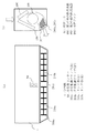
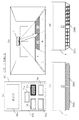
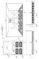
図1に示すように、室内機1は内部に第1の室内熱交換器106、第2の室内熱交換器108、室内ファン109を収納している。吸込口20から吸込まれた空気は、第1の室内熱交換器106、第2の室内熱交換器108、室内ファン109を通過し、吹出し口30から外部へ吹出される。吹出し口30には、吹出し風の風向を制御する左右制御フラップ(左)200a、左右制御フラップ(右)200b、上下制御フラップ(左)201a、上下制御フラップ(右)201bが設けられている。左右制御フラップ(左)200aと左右制御フラップ(右)200bで左右制御フラップを構成し、上下制御フラップ(左)201aと上下制御フラップ(右)201bで上下制御フラップを構成する。また、室内機1の前面の中央下部付近で、吹出し口30から所定距離離間した上方に、赤外線を検知する床温度センサー50を備える。
As shown in FIG. 1, the
先ず、図2により左右制御フラップについて説明する。左右制御フラップは、左右制御フラップ(左)200a、左右制御フラップ(右)200bに分割されている。左右制御フラップ(左)200aは、各フラップがリンク棒(左)210aにより同じ動作を行う。リンク棒(左)210aは、専用のパルスモータで独立して駆動される。また、同様に、左右制御フラップ(右)200bは、各フラップがリンク棒(右)210bにより同じ動作を行う。リンク棒(右)210bは、専用のパルスモータで独立して駆動される。 First, the left and right control flap will be described with reference to FIG. The left / right control flap is divided into a left / right control flap (left) 200a and a left / right control flap (right) 200b. In the left / right control flap (left) 200a, each flap performs the same operation by the link rod (left) 210a. The link rod (left) 210a is independently driven by a dedicated pulse motor. Similarly, the left and right control flap (right) 200b performs the same operation with each flap by the link rod (right) 210b. The link rod (right) 210b is independently driven by a dedicated pulse motor.
図3により、左右制御フラップの動作を説明する。左右制御フラップが、左右制御フラップ(左)200a、左右制御フラップ(右)200bに分割され、夫々独立して駆動されることで、図3のような吹出し気流パターンを作ることができる。左右制御フラップ(左)200a、左右制御フラップ(右)200bを向かって左側に設定すると吹出し気流は左側に(図3(a))、左右制御フラップ(左)200a、左右制御フラップ(右)200bを正面に設定すると吹出し気流は正面に(図3(b))、左右制御フラップ(左)200a、左右制御フラップ(右)200bを向かって右側に設定すると吹出し気流は右側に(図3(c))、左右制御フラップ(左)200aを左側に、左右制御フラップ(右)200bを右側に向けると、吹出し気流は左右に吹き分けられる(図3(d))。左右制御フラップ(左)200aを右側に、左右制御フラップ(右)200bを左側に向けると、吹出し気流は正面を向き、強い気流を正面に吹出すことができる(図3(e))。 The operation of the left / right control flap will be described with reference to FIG. The left / right control flap is divided into a left / right control flap (left) 200a and a left / right control flap (right) 200b, and each is driven independently, whereby a blowout airflow pattern as shown in FIG. 3 can be created. When the left / right control flap (left) 200a and the left / right control flap (right) 200b are set on the left side, the blown airflow is on the left side (FIG. 3 (a)), the left / right control flap (left) 200a, and the left / right control flap (right) 200b. Is set to the front (Fig. 3 (b)), the left and right control flap (left) 200a, the left and right control flap (right) 200b is set to the right side, and the blown air flow is set to the right (Fig. 3 (c). )) When the left / right control flap (left) 200a is directed to the left side and the left / right control flap (right) 200b is directed to the right side, the blown airflow is divided into right and left (FIG. 3 (d)). When the left / right control flap (left) 200a is directed to the right side and the left / right control flap (right) 200b is directed to the left side, the blown airflow can be directed to the front and a strong airflow can be blown to the front (FIG. 3 (e)).
図4により、上下制御フラップについて説明する。図4に示すように、上下制御フラップは、吹出し口30中央部付近において、上下制御フラップ(左)201a、上下制御フラップ(右)201bに分割されている。上下制御フラップ(左)201a、上下制御フラップ(右)201bは、夫々別々のパルスモータにより独立して駆動される。
The vertical control flap will be described with reference to FIG. As shown in FIG. 4, the vertical control flap is divided into a vertical control flap (left) 201 a and a vertical control flap (right) 201 b in the vicinity of the center of the
図5により、上下制御フラップの動作を説明する。上下制御フラップ(左)201a、上下制御フラップ(右)201bを、両方上に向けると気流は部屋の遠方である奥に向かう(図5(a))。上下制御フラップ(左)201a、上下制御フラップ(右)201bを、両方下に向けると気流は部屋の近くの下側に向かう(図5(b))。上下制御フラップ(左)201aを上、上下制御フラップ(右)201bを下に向けると、左側の気流は上へ、右側の気流は下へ向かう(図5(c))。 The operation of the vertical control flap will be described with reference to FIG. When the up / down control flap (left) 201a and the up / down control flap (right) 201b are both directed upward, the airflow is directed to the back of the room (FIG. 5 (a)). When both the vertical control flap (left) 201a and the vertical control flap (right) 201b are directed downward, the airflow is directed downward near the room (FIG. 5B). When the vertical control flap (left) 201a is directed upward and the vertical control flap (right) 201b is directed downward, the left airflow is directed upward and the right airflow is directed downward (FIG. 5 (c)).
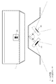
図6に示すように、室内機1は前面の中央部の下部付近に、赤外線を検知する床温度センサー50を有する。床温度センサー50は、赤外線を検知する赤外線検知部を2個備え、一つは室内機1から見て部屋の奥側の床等の温度を検出し、他の一つは室内機1から見て部屋の手前側の床等の温度を検出する。床温度センサー50は、左右方向に回転可能に構成されていて、所定角度の範囲内を、所定の速度で往復運動して、部屋全体の床等の温度を検出する。
As shown in FIG. 6, the
図7に示すように、部屋の床を6つのエリア(イ〜ヘ)に分割する。室内機1から見て部屋の手前側を3つのエリア(イ、ロ、ハ)に、室内機1から見て部屋の奥側を3つのエリア(ニ、ホ、ヘ)に分割する。
As shown in FIG. 7, the floor of the room is divided into six areas (A to F). The front side of the room as viewed from the
図8により、リモコン60について説明する。リモコン60は、表示部60aと、エリア指定操作部60bとを備える。その他の運転入/切ボタン、冷/暖/除湿切替ボタン、温度設定ボタン等は、省略している。エリア指定操作部60bは、部屋の床エリアの全体を指定するエリア全体指定ボタン70a、エリア(イ、ロ)を指定する第1のエリア指定ボタン70b、エリア(ロ、ハ)を指定する第2のエリア指定ボタン70c、エリア(ニ、ホ)を指定する第3のエリア指定ボタン70d、エリア(ホ、ヘ)を指定する第4のエリア指定ボタン70eを備える。尚、このリモコン60のエリア指定操作部60bの操作と部屋の床のエリアとの関係についての詳細は、後述する。
The
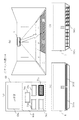
図9により、空気調和機の冷媒回路について、簡単に説明する。冷媒を圧縮して吐出する圧縮機101の吐出側に、冷房と暖房とで冷媒の流れる方向を切り替える四方弁102が接続される。四方弁102に室外熱交換器103が接続され、室外熱交換器103の近くに室外ファン104が配置される。減圧装置である第1の膨張弁105が室外熱交換器103に接続され、第1の膨張弁105は、開閉弁112、延長配管114を介して第1の室内熱交換器106に接続される。第1の室内熱交換器106は、第2の膨張弁107を介して第2の室内熱交換器108に接続される。第1の室内熱交換器106及び第2の室内熱交換器108の近くに、室内ファン109が配置されている。第2の室内熱交換器108は、延長配管113、開閉弁111を介して四方弁102に接続される。四方弁102からアキュムレータ110を介して圧縮機101に戻る。
The refrigerant circuit of the air conditioner will be briefly described with reference to FIG. A four-
尚、冷房運転時に、第1の膨張弁105を開き気味にして第2の膨張弁107を絞り、第1の室内熱交換器106を凝縮器として、第2の室内熱交換器108を蒸発器として動作させることで除湿運転を行うことができる。
During the cooling operation, the
図10により、リモコン60のエリア指定操作部60bによる指定と、部屋の床の指定エリアとの関係を説明する。リモコン60のエリア指定操作部60bには、エリア全体指定ボタン70a以外に、第1のエリア指定ボタン70b、第2のエリア指定ボタン70c、第3のエリア指定ボタン70d、第4のエリア指定ボタン70eの4個のエリア指定ボタンがある。
The relationship between the designation by the area
4個のエリア指定ボタンの1個を指定するパターンが4つあり、第1のエリア指定ボタン70bを指定するパターンを「パターン名称1−1」とする。同様に、第2のエリア指定ボタン70cを指定するパターンを「パターン名称1−2」、第3のエリア指定ボタン70dを指定するパターンを「パターン名称1−3」、第4のエリア指定ボタン70eを指定するパターンを「パターン名称1−4」とする。
There are four patterns for designating one of the four area designation buttons, and the pattern for designating the first
4個のエリア指定ボタンの2個を指定するパターンが6つあり、第1のエリア指定ボタン70bと第2のエリア指定ボタン70cを指定するパターンを「パターン名称2−1」、第1のエリア指定ボタン70bと第3のエリア指定ボタン70dを指定するパターンを「パターン名称2−2」、第1のエリア指定ボタン70bと第4のエリア指定ボタン70eを指定するパターンを「パターン名称2−3」、第2のエリア指定ボタン70cと第3のエリア指定ボタン70dを指定するパターンを「パターン名称2−4」、第2のエリア指定ボタン70cと第4のエリア指定ボタン70eを指定するパターンを「パターン名称2−5」、第3のエリア指定ボタン70dと第4のエリア指定ボタン70eを指定するパターンを「パターン名称2−6」とする。
There are six patterns for designating two of the four area designation buttons, the pattern for designating the first
4個のエリア指定ボタンの3個を指定するパターンが4つあり、第1のエリア指定ボタン70bと第2のエリア指定ボタン70cと第3のエリア指定ボタン70dとを指定するパターンを「パターン名称3−1」、第1のエリア指定ボタン70bと第2のエリア指定ボタン70cと第4のエリア指定ボタン70eとを指定するパターンを「パターン名称3−2」、第1のエリア指定ボタン70bと第3のエリア指定ボタン70dと第4のエリア指定ボタン70eとを指定するパターンを「パターン名称3−3」、第2のエリア指定ボタン70cと第3のエリア指定ボタン70dと第4のエリア指定ボタン70eとを指定するパターンを「パターン名称3−4」とする。
There are four patterns for designating three of the four area designation buttons. A pattern for designating the first
4個のエリア指定ボタンの全てを指定するパターンが1つあり、「パターン名称4−1」とする。この「パターン名称4−1」の場合は、エリア全体指定ボタン70aを指定してもよい。結局、全部で15パターンある。
There is one pattern that designates all of the four area designation buttons, which is “pattern name 4-1”. In the case of this “pattern name 4-1,” the entire
各パターン名称に対応する部屋の床のエリアは、図10に示すようになる。即ち、「パターン名称1−1」には、「エリア(イ)とエリア(ロ)」が対応する。以下、同様に、「パターン名称1−2」には「エリア(ロ)とエリア(ハ)」、「パターン名称1−3」には「エリア(ニ)とエリア(ホ)」、「パターン名称1−4」には「エリア(ホ)とエリア(ヘ)」が対応する。 The floor area of the room corresponding to each pattern name is as shown in FIG. That is, “Pattern name 1-1” corresponds to “Area (A) and Area (B)”. Similarly, “Pattern name 1-2” includes “Area (B) and Area (C)”, “Pattern name 1-3” includes “Area (D) and Area (E)”, and “Pattern name”. “1-4” corresponds to “area (e) and area (f)”.
「パターン名称2−1」には「エリア(イ)とエリア(ロ)とエリア(ハ)」、「パターン名称2−2」には「エリア(イ)とエリア(ロ)とエリア(ニ)とエリア(ホ)」、「パターン名称2−3」には「エリア(イ)とエリア(ロ)とエリア(ホ)とエリア(ヘ)」、「パターン名称2−4」には「エリア(ロ)とエリア(ハ)とエリア(ニ)とエリア(ホ)」、「パターン名称2−5」には「エリア(ロ)とエリア(ハ)とエリア(ホ)とエリア(ヘ)」、「パターン名称2−6」には「エリア(ニ)とエリア(ホ)とエリア(ヘ)」が対応する。 “Pattern name 2-1” includes “Area (A), Area (B), and Area (C)”, and “Pattern name 2-2” includes “Area (A), Area (B), and Area (D)”. "Area (e)", "pattern name 2-3" is "area (b), area (b), area (e), area (f)", and "pattern name 2-4" is "area ( (B), area (c), area (d), area (e) "and" pattern name 2-5 "include" area (b), area (c), area (e), area (f) ", “Pattern name 2-6” corresponds to “area (d), area (e) and area (f)”.
「パターン名称3−1」には「エリア(イ)とエリア(ロ)とエリア(ハ)とエリア(ニ)とエリア(ホ)」、「パターン名称3−2」には「エリア(イ)とエリア(ロ)とエリア(ハ)とエリア(ホ)とエリア(ヘ)」、「パターン名称3−3」には「エリア(イ)とエリア(ロ)とエリア(ニ)とエリア(ホ)とエリア(ヘ)」、「パターン名称3−4」には「エリア(ロ)とエリア(ハ)とエリア(ニ)とエリア(ホ)とエリア(ヘ)」が対応する。 “Pattern name 3-1” includes “Area (A), Area (B), Area (C), Area (D), Area (E)”, and “Pattern name 3-2” includes “Area (A) "Area (b)", "area (c)", "area (e) and area (f)" and "pattern name 3-3" include "area (b), area (b), area (d) and area (e) ), Area (f) ", and" pattern name 3-4 "correspond to" area (b), area (c), area (d), area (e), and area (f) ".
「パターン名称4−1」には「エリア(イ)とエリア(ロ)とエリア(ハ)とエリア(ニ)とエリア(ホ)とエリア(ヘ)」が対応する。 “Pattern name 4-1” corresponds to “Area (A), Area (B), Area (C), Area (D), Area (E) and Area (F)”.
次に、各パターン毎の制御フラップの動作を図11乃至図19により説明する。先ず、「パターン名称1−1」の場合は、図11に示すように、リモコン60の第1のエリア指定ボタン70bが指定され、室内機1からの吹出し気流は、初期設定として、エリア(イ)とエリア(ロ)の中間の位置に上下風向、左右風向を向ける。具体的には、上下制御フラップ(左)201aと上下制御フラップ(右)201bは下に向ける。左右制御フラップ(左)200aは、左に向ける(室内機1を正面から見た場合、以下、同様)。左右制御フラップ(右)200bは、正面に向いている。これは、中央のエリアであるエリア(ロ)にも気流を送るためである。
Next, the operation of the control flap for each pattern will be described with reference to FIGS. First, in the case of “pattern name 1-1”, as shown in FIG. 11, the first
「パターン名称1−2」の場合は、図12に示すように、リモコン60の第2のエリア指定ボタン70cが指定され、室内機1からの吹出し気流は、初期設定として、エリア(ロ)とエリア(ハ)の中間の位置に上下風向、左右風向を向ける。具体的には、上下制御フラップ(左)201aと上下制御フラップ(右)201bは下に向ける。左右制御フラップ(左)200aは、正面に向ける。左右制御フラップ(右)200bは、右に向ける。
In the case of “pattern name 1-2”, as shown in FIG. 12, the second
「パターン名称1−3」の場合は、図13に示すように、リモコン60の第3のエリア指定ボタン70dが指定され、室内機1からの吹出し気流は、初期設定として、エリア(ニ)とエリア(ホ)の中間の位置に上下風向、左右風向を向ける。具体的には、上下制御フラップ(左)201aと上下制御フラップ(右)201bは上に向ける。左右制御フラップ(左)200aは、左に向ける。左右制御フラップ(右)200bは、正面に向ける。
In the case of “Pattern name 1-3”, as shown in FIG. 13, the third
「パターン名称1−4」の場合は、図14に示すように、リモコン60の第4のエリア指定ボタン70eが指定され、室内機1からの吹出し気流は、初期設定として、エリア(ホ)とエリア(ヘ)の中間の位置に上下風向、左右風向を向ける。具体的には、上下制御フラップ(左)201aと上下制御フラップ(右)201bは上に向ける。左右制御フラップ(左)200aは、正面に向ける。左右制御フラップ(右)200bは、右に向ける。
In the case of “pattern name 1-4”, as shown in FIG. 14, the fourth
次に、リモコン60のエリア指定ボタンの2個が指定される場合について説明するが、6つのパターンの中の、「パターン名称2−2」、「パターン名称2−3」、「パターン名称2−6」について説明する。
Next, a case where two of the area designation buttons of the
「パターン名称2−2」の場合は、図15に示すように、リモコン60の第1のエリア指定ボタン70bと第3のエリア指定ボタン70dが指定され、室内機1からの吹出し気流は、初期設定として、エリア(イ)とエリア(ロ)とエリア(ニ)とエリア(ホ)の中央の位置に上下風向、左右風向を向ける。具体的には、上下制御フラップ(左)201aと上下制御フラップ(右)201bはやや上に向ける(「パターン名称1−3」よりは若干下に向ける)。左右制御フラップ(左)200aは、左に向ける。左右制御フラップ(右)200bは、正面に向ける。
In the case of “pattern name 2-2”, the first
「パターン名称2−3」の場合は、図16に示すように、リモコン60の第1のエリア指定ボタン70bと第4のエリア指定ボタン70eが指定され、室内機1からの吹出し気流は、初期設定として、エリア(イ)とエリア(ロ)の中間、エリア(ホ)とエリア(ヘ)の中間の位置に上下風向、左右風向を向ける。具体的には、上下制御フラップ(左)201aは下、上下制御フラップ(右)201bは上に向ける。左右制御フラップ(左)200aは、左に向ける。左右制御フラップ(右)200bは、右に向ける。このような気流の吹き分けができるのは、上下制御フラップを2分割したことによる。一枚の上下制御フラップでは、このような気流の吹き分けはできない。
In the case of “Pattern name 2-3”, as shown in FIG. 16, the first
「パターン名称2−6」の場合は、図17に示すように、リモコン60の第3のエリア指定ボタン70dと第4のエリア指定ボタン70eが指定され、室内機1からの吹出し気流は、初期設定として、エリア(ニ)とエリア(ホ)の中間、エリア(ホ)とエリア(ヘ)の中間の位置に上下風向、左右風向を向ける。具体的には、上下制御フラップ(左)201aと上下制御フラップ(右)201bは上に向ける。左右制御フラップ(左)200aは、左に向ける。左右制御フラップ(右)200bは、右に向ける。
In the case of “pattern name 2-6”, the third
リモコン60の4個のエリア指定ボタンの中の3個が指定されるパターンは4つあるが、「パターン名称3−3」について説明する。
There are four patterns in which three of the four area designation buttons of the
「パターン名称3−3」の場合は、図18に示すように、リモコン60の第1のエリア指定ボタン70bと第3のエリア指定ボタン70dと第4のエリア指定ボタン70eが指定され、室内機1からの吹出し気流は、初期設定として、エリア(イ)とエリア(ロ)とエリア(ニ)とエリア(ホ)の中央、エリア(ホ)とエリア(ヘ)の中間の位置に上下風向、左右風向を向ける。具体的には、上下制御フラップ(左)201aはやや上に、上下制御フラップ(右)201bは上に向ける。左右制御フラップ(左)200aは、左に向ける。左右制御フラップ(右)200bは、右に向ける。
In the case of “pattern name 3-3”, as shown in FIG. 18, the first
リモコン60の4個のエリア指定ボタンの中の全てが指定されるパターンである、「パターン名称4−1」について説明する。
The “pattern name 4-1”, which is a pattern in which all of the four area designation buttons of the
「パターン名称4−1」の場合は、図19に示すように、リモコン60の全てのエリア指定ボタンが指定される。室内機1からの吹出し気流は、初期設定として、エリア(イ)とエリア(ロ)とエリア(ニ)とエリア(ホ)の中央、エリア(ロ)とエリア(ハ)とエリア(ホ)とエリア(ヘ)の中央の位置に上下風向、左右風向を向ける。具体的には、上下制御フラップ(左)201aと上下制御フラップ(右)201bはやや上に向ける。左右制御フラップ(左)200aは、左に向ける。左右制御フラップ(右)200bは、右に向ける。
In the case of “pattern name 4-1,” all area designation buttons of the
吹出し気流の初期設定は以上のとおりであるが、図20のフローチャートにより、その後の制御について説明する。
ユーザが、リモコン60のエリア指定操作部60bを操作して空調したい(吹出し気流を送ってほしい)エリアを選択する(S10)。室内機1は、指定されたエリアに吹出し気流を送るように、風向、風速の初期値を設定して実行し、後述する体感温度と設定温度との差が所定値以内になるまで続ける(S20)。床温度センサー50は、指定エリア(2乃至6箇所のエリア)の床温度を検出し、床温度の最大値と最小値の差を算出する(S30)。指定エリアの床温度の最大値と最小値の差がしきい値を超えたか判定する(S40)。指定エリアの床温度の最大値と最小値の差がしきい値を超えた場合は、しきい値以下になるように、室内機1は風向、風速の補正を行う(S50)。
Although the initial setting of the blowing airflow is as described above, the subsequent control will be described with reference to the flowchart of FIG.
The user operates the area
以上のように、温度ムラを解消するために、上下制御フラップ、左右制御フラップを左右に分割した気流制御によって広いリビングでの快適性が向上する。さらに、リモコン60による空調したいエリア指定に対応した床温度による空調ができるので、ユーザの要求を満たした快適性を維持しつつ、省エネ運転が可能となる。
As described above, in order to eliminate the temperature unevenness, vertical control flaps, comfort in a wide living by divided airflow control the left and right control flaps on the left and right improves. Furthermore, since air conditioning can be performed at the floor temperature corresponding to the area designation to be air-conditioned by the
空気調和機の能力は、室内ファン109の風量と、圧縮機101の運転周波数とによって制御される。リモコン60の設定温度に対して、室内機1の吸込み温度が離れるほど、室内ファン109の風量と圧縮機101の運転周波数とを上げて能力を上げる。また、リモコン60の設定温度に対して、室内機1の吸込み温度が近づくほど、室内ファン109の風量と圧縮機101の運転周波数とを下げて能力を下げる。室内機1の吸込み温度Taと、床温度センサー50により検出された床温度Tfから算出される体感温度Ttaikanは、次式で計算される。
Ttaikan=Ta+α(Tf−Ta)・・(1)
ここで、αは定数である。
(1)式で算出される体感温度は、室温より床温度が高いと体感温度は上昇し、室温より床温度が低いと体感温度は低下する。また、定数αは体感温度に対する床温度の寄与度を表すものであり、一般的に0.5前後の値である。また、体感温度を算出する床温度は、リモコン60で指定されたエリアの床温度の平均値を用いる。
The capacity of the air conditioner is controlled by the air volume of the
Ttaikan = Ta + α ( Tf−Ta ) (1)
Here, α is a constant.
The perceived temperature calculated by the equation (1) increases when the floor temperature is higher than room temperature, and decreases when the floor temperature is lower than room temperature. The constant α represents the contribution of the floor temperature to the body temperature, and is generally a value around 0.5. In addition, as the floor temperature for calculating the sensible temperature, the average value of the floor temperatures in the area designated by the
この床温度を考慮した体感温度で、空気調和機の能力を制御することにより、快適性が向上し、且つ省エネ運転が可能になる。 By controlling the performance of the air conditioner at the sensible temperature considering the floor temperature, comfort is improved and energy-saving operation is possible.
実施の形態2.
図21、22は実施の形態2を示す図で、図21は一枚の上下制御フラップ201を使用した室内機1の正面図(a)と断面図(b)、図22は上下制御フラップ201の動作を示す室内機1の正面図である。
21 and 22 are diagrams showing the second embodiment. FIG. 21 is a front view (a) and a cross-sectional view (b) of the
実施の形態1では、左右に分割された上下制御フラップを使用したが、一枚の上下制御フラップ201でも、同様の吹出し気流の制御が可能である。
In the first embodiment, the vertical control flaps divided into left and right are used, but the same control of the blown airflow is possible with a single
図21で、図4と異なるのは、上下制御フラップ201が一枚で構成されている点のみである。
FIG. 21 is different from FIG. 4 only in that the
図22に上下制御フラップ201の動作を示すが、図22(a)のように上下制御フラップ201を上に向ければ、吹出し気流は上向きに吹出されて、遠方(部屋の奥)に向かう。また、図22(b)のように上下制御フラップ201を下に向ければ、吹出し気流は下向きに吹出されて、近く(部屋の手前)に向かう。
FIG. 22 shows the operation of the
一枚の上下制御フラップ201を使用する場合は、図10に示す15パターンの中の、「パターン名称2−3」、「パターン名称2−4」、「パターン名称3−1」、「パターン名称3−2」、「パターン名称3−3」、「パターン名称3−4」を除く、他の9パターンは可能である。
When one
以上のように、一枚の上下制御フラップ201でも、吹出し気流の吹き分けパターン数は減るが、実施の形態1に近い快適性の向上と、省エネを実現できる。
As described above, even with one
1 室内機、20 吸込口、30 吹出し口、50 床温度センサー、60 リモコン、60a 表示部、60b エリア指定操作部、70a エリア全体指定ボタン、70b 第1のエリア指定ボタン、70c 第2のエリア指定ボタン、70d 第3のエリア指定ボタン、70e 第4のエリア指定ボタン、101 圧縮機、102 四方弁、103 室外熱交換器、104 室外ファン、105 第1の膨張弁、106 第1の室内熱交換器、107 第2の膨張弁、108 第2の室内熱交換器、109 室内ファン、110 アキュムレータ、111 開閉弁、112 開閉弁、113 延長配管、114 延長配管、200a 左右制御フラップ(左)、200b 左右制御フラップ(右)、201 上下制御フラップ、201a 上下制御フラップ(左)、201b 上下制御フラップ(右)、210a リンク棒(左)、210b リンク棒(右)。
DESCRIPTION OF
Claims (4)
この室内機に設けられ、部屋の床温度を検出する可動式の床温度センサーと、
前記室内機に収納された室内ファンと、
前記室内機の吹出し口に設けられ、この吹出し口から吹出される吹出し気流の上下風向を制御する一枚の又は左右に分割された上下制御フラップと、
前記室内機の吹出し口に設けられ、この吹出し口から吹出される吹出し気流の左右風向を制御する左右に分割された左右制御フラップと、
前記部屋の床が複数に分割され、これら分割された複数のエリアの中からユーザが前記吹出し気流を送る2つ以上のエリアを指定エリアとして指定するエリア指定操作部を有するリモコンとを備え、
このリモコンからエリア指定の信号が送信された場合、前記室内機は、部屋の床を分割した複数のエリアの中から、前記指定エリアに対応する2つ以上のエリアを判定して、前記2つ以上のエリアの中間又は中央に向けて前記吹出し気流が送られるように、前記吹出し気流の風向、風速の初期値を設定して運転を開始するとともに、前記床温度センサーが検出した指定エリアの床温度に基づいて指定エリアにおける体感温度を算出し、指定エリアにおける体感温度と予め設定されている設定温度との差が所定値以内になるように運転することを特徴とする空気調和機。 Indoor unit,
A movable floor temperature sensor that is installed in this indoor unit and detects the floor temperature of the room,
An indoor fan housed in the indoor unit;
A vertical control flap that is provided at the outlet of the indoor unit and that controls the vertical airflow direction of the blown airflow blown from the outlet, or is divided into left and right parts;
A left and right control flap that is provided at the outlet of the indoor unit and that is divided into right and left to control the left and right wind direction of the blown airflow blown from the outlet;
The floor of the room is divided into a plurality, and a remote control having an area designation operation unit for designating two or more areas from which the user sends the blowing airflow as designated areas from among the divided areas .
When an area designation signal is transmitted from the remote controller, the indoor unit determines two or more areas corresponding to the designated area from a plurality of areas obtained by dividing the floor of the room, and the two The initial direction of the wind direction and the wind speed of the blown airflow is set so that the blown airflow is sent toward the middle or center of the above areas, and the operation is started, and the floor of the designated area detected by the floor temperature sensor An air conditioner that calculates a sensible temperature in a designated area based on the temperature and operates so that a difference between the sensible temperature in the designated area and a preset set temperature is within a predetermined value.
前記室内機は、リモコンのエリア指定操作部の一つ又は複数のエリア指定ボタンで指定された指定エリアのパターンに応じて、前記上下制御フラップと前記左右制御フラップとの向きを初期設定して、前記指定エリアに前記吹出し気流を送ることを特徴とする請求項1又は2又は3記載の空気調和機。The indoor unit is configured to initially set the direction of the vertical control flap and the horizontal control flap according to the pattern of the designated area designated by one or more area designation buttons of the area designation operation unit of the remote control, The air conditioner according to claim 1, wherein the blown airflow is sent to the designated area.
Priority Applications (1)
| Application Number | Priority Date | Filing Date | Title |
|---|---|---|---|
| JP2005339622A JP4478099B2 (en) | 2005-11-25 | 2005-11-25 | Air conditioner |
Applications Claiming Priority (1)
| Application Number | Priority Date | Filing Date | Title |
|---|---|---|---|
| JP2005339622A JP4478099B2 (en) | 2005-11-25 | 2005-11-25 | Air conditioner |
Publications (3)
| Publication Number | Publication Date |
|---|---|
| JP2007147120A JP2007147120A (en) | 2007-06-14 |
| JP2007147120A5 JP2007147120A5 (en) | 2007-11-22 |
| JP4478099B2 true JP4478099B2 (en) | 2010-06-09 |
Family
ID=38208739
Family Applications (1)
| Application Number | Title | Priority Date | Filing Date |
|---|---|---|---|
| JP2005339622A Active JP4478099B2 (en) | 2005-11-25 | 2005-11-25 | Air conditioner |
Country Status (1)
| Country | Link |
|---|---|
| JP (1) | JP4478099B2 (en) |
Cited By (2)
| Publication number | Priority date | Publication date | Assignee | Title |
|---|---|---|---|---|
| CN103175291A (en) * | 2011-12-20 | 2013-06-26 | 三菱电机株式会社 | Indoor unit of air-conditioning apparatus |
| WO2019024824A1 (en) * | 2017-08-01 | 2019-02-07 | 青岛海尔空调器有限总公司 | Indoor unit of wall-mounted air conditioner and control method therefor |
Families Citing this family (18)
| Publication number | Priority date | Publication date | Assignee | Title |
|---|---|---|---|---|
| JP4589371B2 (en) | 2007-10-05 | 2010-12-01 | 三菱電機株式会社 | Air conditioner |
| JP5123680B2 (en) * | 2008-01-31 | 2013-01-23 | 三菱重工業株式会社 | Air conditioner area air conditioning method and air conditioner |
| JP5063509B2 (en) * | 2008-06-30 | 2012-10-31 | 三菱電機株式会社 | Air conditioner |
| JP5369577B2 (en) * | 2008-09-25 | 2013-12-18 | ダイキン工業株式会社 | Air conditioning system |
| JP5213050B2 (en) * | 2009-02-27 | 2013-06-19 | シャープ株式会社 | Air conditioner |
| JP5504845B2 (en) * | 2009-11-25 | 2014-05-28 | ダイキン工業株式会社 | Air conditioning controller |
| JP5025764B2 (en) * | 2010-06-25 | 2012-09-12 | 三菱電機株式会社 | Air conditioner |
| CN103154620B (en) * | 2010-08-04 | 2016-04-13 | 三菱电机株式会社 | The indoor set of air conditioner and air conditioner |
| JP5220068B2 (en) * | 2010-08-04 | 2013-06-26 | 三菱電機株式会社 | Air conditioner indoor unit and air conditioner |
| JP2012063077A (en) * | 2010-09-16 | 2012-03-29 | Panasonic Corp | Remote controller for air conditioner |
| EP2618068A4 (en) * | 2010-09-17 | 2018-10-31 | Mitsubishi Electric Corporation | Air conditioning system and air conditioning method |
| JP6301634B2 (en) * | 2013-11-11 | 2018-03-28 | シャープ株式会社 | Air conditioner |
| JP6385068B2 (en) * | 2014-02-18 | 2018-09-05 | 三菱電機株式会社 | Air conditioner |
| US10739033B2 (en) * | 2015-08-06 | 2020-08-11 | Mitsubishi Electric Corporation | Air-conditioning apparatus |
| JP2017180990A (en) * | 2016-03-31 | 2017-10-05 | サンデン・リテールシステム株式会社 | Air conditioner |
| CN107246717B (en) * | 2017-06-30 | 2020-05-29 | 青岛海尔空调器有限总公司 | Air conditioner and air ducting thereof |
| JP6956594B2 (en) * | 2017-11-01 | 2021-11-02 | 三菱電機株式会社 | Air conditioner |
| CN113137656A (en) * | 2020-01-20 | 2021-07-20 | 芜湖美的厨卫电器制造有限公司 | Temperature control device, method and system |
-
2005
- 2005-11-25 JP JP2005339622A patent/JP4478099B2/en active Active
Cited By (3)
| Publication number | Priority date | Publication date | Assignee | Title |
|---|---|---|---|---|
| CN103175291A (en) * | 2011-12-20 | 2013-06-26 | 三菱电机株式会社 | Indoor unit of air-conditioning apparatus |
| CN103175291B (en) * | 2011-12-20 | 2015-11-18 | 三菱电机株式会社 | The indoor set of air conditioner |
| WO2019024824A1 (en) * | 2017-08-01 | 2019-02-07 | 青岛海尔空调器有限总公司 | Indoor unit of wall-mounted air conditioner and control method therefor |
Also Published As
| Publication number | Publication date |
|---|---|
| JP2007147120A (en) | 2007-06-14 |
Similar Documents
| Publication | Publication Date | Title |
|---|---|---|
| JP4478099B2 (en) | Air conditioner | |
| US7881827B2 (en) | Air conditioner and method of operating the same | |
| US8364317B2 (en) | Air conditioner and method of operating the same | |
| JP3807305B2 (en) | Air conditioner | |
| JPWO2018229923A1 (en) | Air conditioner indoor unit | |
| JP5312434B2 (en) | Air conditioner | |
| JP2013088087A (en) | Air conditioner | |
| JPH0650595A (en) | Air conditioner | |
| JP6161452B2 (en) | Air conditioner system | |
| JP4225137B2 (en) | Indoor panel of air conditioner and air conditioner | |
| JP2006162197A (en) | Air conditioner | |
| JP2018059675A (en) | Air conditioner | |
| JP4274293B2 (en) | Air conditioner | |
| JP6178992B2 (en) | Air conditioner | |
| JP2009133536A (en) | Air conditioner | |
| JP2007024416A (en) | Air conditioner | |
| JP3306126B2 (en) | Air conditioner | |
| AU2015334400B2 (en) | Air conditioning apparatus | |
| JPH0526508A (en) | Air conditioner | |
| JP2013088072A (en) | Air conditioner | |
| JPH05296548A (en) | Air conditioner | |
| JP2011080625A (en) | Air conditioner | |
| JPH08178344A (en) | Air conditioner | |
| JPH03274347A (en) | Air conditioner | |
| JP2003240325A (en) | Air conditioner |
Legal Events
| Date | Code | Title | Description |
|---|---|---|---|
| A521 | Written amendment |
Free format text: JAPANESE INTERMEDIATE CODE: A523 Effective date: 20071004 |
|
| A621 | Written request for application examination |
Free format text: JAPANESE INTERMEDIATE CODE: A621 Effective date: 20071004 |
|
| A131 | Notification of reasons for refusal |
Free format text: JAPANESE INTERMEDIATE CODE: A131 Effective date: 20091027 |
|
| A521 | Written amendment |
Free format text: JAPANESE INTERMEDIATE CODE: A523 Effective date: 20091211 |
|
| TRDD | Decision of grant or rejection written | ||
| A01 | Written decision to grant a patent or to grant a registration (utility model) |
Free format text: JAPANESE INTERMEDIATE CODE: A01 Effective date: 20100309 |
|
| A01 | Written decision to grant a patent or to grant a registration (utility model) |
Free format text: JAPANESE INTERMEDIATE CODE: A01 |
|
| A61 | First payment of annual fees (during grant procedure) |
Free format text: JAPANESE INTERMEDIATE CODE: A61 Effective date: 20100312 |
|
| R150 | Certificate of patent or registration of utility model |
Ref document number: 4478099 Country of ref document: JP Free format text: JAPANESE INTERMEDIATE CODE: R150 Free format text: JAPANESE INTERMEDIATE CODE: R150 |
|
| FPAY | Renewal fee payment (event date is renewal date of database) |
Free format text: PAYMENT UNTIL: 20130319 Year of fee payment: 3 |
|
| FPAY | Renewal fee payment (event date is renewal date of database) |
Free format text: PAYMENT UNTIL: 20130319 Year of fee payment: 3 |
|
| FPAY | Renewal fee payment (event date is renewal date of database) |
Free format text: PAYMENT UNTIL: 20140319 Year of fee payment: 4 |
|
| R250 | Receipt of annual fees |
Free format text: JAPANESE INTERMEDIATE CODE: R250 |
|
| R250 | Receipt of annual fees |
Free format text: JAPANESE INTERMEDIATE CODE: R250 |
|
| R250 | Receipt of annual fees |
Free format text: JAPANESE INTERMEDIATE CODE: R250 |
|
| R250 | Receipt of annual fees |
Free format text: JAPANESE INTERMEDIATE CODE: R250 |
|
| R250 | Receipt of annual fees |
Free format text: JAPANESE INTERMEDIATE CODE: R250 |
|
| R250 | Receipt of annual fees |
Free format text: JAPANESE INTERMEDIATE CODE: R250 |
|
| R250 | Receipt of annual fees |
Free format text: JAPANESE INTERMEDIATE CODE: R250 |
|
| R250 | Receipt of annual fees |
Free format text: JAPANESE INTERMEDIATE CODE: R250 |