JP4477810B2 - Cleaning method of passage using mixed phase flow of gas and liquid - Google Patents
Cleaning method of passage using mixed phase flow of gas and liquid Download PDFInfo
- Publication number
- JP4477810B2 JP4477810B2 JP2001587935A JP2001587935A JP4477810B2 JP 4477810 B2 JP4477810 B2 JP 4477810B2 JP 2001587935 A JP2001587935 A JP 2001587935A JP 2001587935 A JP2001587935 A JP 2001587935A JP 4477810 B2 JP4477810 B2 JP 4477810B2
- Authority
- JP
- Japan
- Prior art keywords
- liquid
- flow
- gas
- cleaning
- mixed phase
- Prior art date
- Legal status (The legal status is an assumption and is not a legal conclusion. Google has not performed a legal analysis and makes no representation as to the accuracy of the status listed.)
- Expired - Fee Related
Links
- 239000007788 liquid Substances 0.000 title claims abstract description 162
- 238000000034 method Methods 0.000 title claims abstract description 110
- 238000004140 cleaning Methods 0.000 title abstract description 161
- 239000000356 contaminant Substances 0.000 claims abstract description 40
- 239000000203 mixture Substances 0.000 claims abstract description 21
- 239000004094 surface-active agent Substances 0.000 claims description 41
- 239000002245 particle Substances 0.000 claims description 21
- 239000007787 solid Substances 0.000 claims description 19
- LFQSCWFLJHTTHZ-UHFFFAOYSA-N Ethanol Chemical compound CCO LFQSCWFLJHTTHZ-UHFFFAOYSA-N 0.000 claims description 16
- 230000015572 biosynthetic process Effects 0.000 claims description 13
- 239000007800 oxidant agent Substances 0.000 claims description 8
- 239000002518 antifoaming agent Substances 0.000 claims description 4
- 239000003139 biocide Substances 0.000 claims description 4
- 239000003906 humectant Substances 0.000 claims description 4
- 239000002738 chelating agent Substances 0.000 claims description 2
- 239000004034 viscosity adjusting agent Substances 0.000 claims description 2
- 239000003002 pH adjusting agent Substances 0.000 claims 1
- 239000012528 membrane Substances 0.000 abstract description 113
- 239000007864 aqueous solution Substances 0.000 abstract description 11
- 239000007789 gas Substances 0.000 description 109
- 239000012071 phase Substances 0.000 description 85
- XLYOFNOQVPJJNP-UHFFFAOYSA-N water Substances O XLYOFNOQVPJJNP-UHFFFAOYSA-N 0.000 description 78
- 239000000243 solution Substances 0.000 description 76
- 239000012530 fluid Substances 0.000 description 50
- 230000004907 flux Effects 0.000 description 27
- 230000035882 stress Effects 0.000 description 27
- MHAJPDPJQMAIIY-UHFFFAOYSA-N Hydrogen peroxide Chemical compound OO MHAJPDPJQMAIIY-UHFFFAOYSA-N 0.000 description 26
- 238000005406 washing Methods 0.000 description 26
- 239000012510 hollow fiber Substances 0.000 description 25
- 239000000126 substance Substances 0.000 description 24
- 230000001954 sterilising effect Effects 0.000 description 23
- 241000894006 Bacteria Species 0.000 description 21
- 238000004659 sterilization and disinfection Methods 0.000 description 20
- 238000001574 biopsy Methods 0.000 description 18
- 239000010410 layer Substances 0.000 description 18
- -1 polyethylene Polymers 0.000 description 17
- 230000000694 effects Effects 0.000 description 16
- 230000009471 action Effects 0.000 description 15
- 239000006260 foam Substances 0.000 description 15
- 230000005514 two-phase flow Effects 0.000 description 14
- 239000000463 material Substances 0.000 description 13
- 239000003595 mist Substances 0.000 description 13
- 239000000835 fiber Substances 0.000 description 12
- CURLTUGMZLYLDI-UHFFFAOYSA-N Carbon dioxide Chemical compound O=C=O CURLTUGMZLYLDI-UHFFFAOYSA-N 0.000 description 10
- SUKJFIGYRHOWBL-UHFFFAOYSA-N sodium hypochlorite Chemical compound [Na+].Cl[O-] SUKJFIGYRHOWBL-UHFFFAOYSA-N 0.000 description 10
- 238000011010 flushing procedure Methods 0.000 description 9
- 230000006872 improvement Effects 0.000 description 9
- 239000002736 nonionic surfactant Substances 0.000 description 9
- 230000008569 process Effects 0.000 description 9
- 238000000108 ultra-filtration Methods 0.000 description 9
- 229910019093 NaOCl Inorganic materials 0.000 description 8
- 239000003945 anionic surfactant Substances 0.000 description 8
- 230000001580 bacterial effect Effects 0.000 description 8
- 210000004369 blood Anatomy 0.000 description 8
- 239000008280 blood Substances 0.000 description 8
- 239000000306 component Substances 0.000 description 8
- 235000014113 dietary fatty acids Nutrition 0.000 description 8
- 239000000194 fatty acid Substances 0.000 description 8
- 229930195729 fatty acid Natural products 0.000 description 8
- 239000012466 permeate Substances 0.000 description 8
- 238000001223 reverse osmosis Methods 0.000 description 7
- 239000000344 soap Substances 0.000 description 7
- QTBSBXVTEAMEQO-UHFFFAOYSA-N Acetic acid Chemical compound CC(O)=O QTBSBXVTEAMEQO-UHFFFAOYSA-N 0.000 description 6
- VTYYLEPIZMXCLO-UHFFFAOYSA-L Calcium carbonate Chemical compound [Ca+2].[O-]C([O-])=O VTYYLEPIZMXCLO-UHFFFAOYSA-L 0.000 description 6
- KFSLWBXXFJQRDL-UHFFFAOYSA-N Peracetic acid Chemical compound CC(=O)OO KFSLWBXXFJQRDL-UHFFFAOYSA-N 0.000 description 6
- CDBYLPFSWZWCQE-UHFFFAOYSA-L Sodium Carbonate Chemical compound [Na+].[Na+].[O-]C([O-])=O CDBYLPFSWZWCQE-UHFFFAOYSA-L 0.000 description 6
- UIIMBOGNXHQVGW-UHFFFAOYSA-M Sodium bicarbonate Chemical compound [Na+].OC([O-])=O UIIMBOGNXHQVGW-UHFFFAOYSA-M 0.000 description 6
- HEMHJVSKTPXQMS-UHFFFAOYSA-M Sodium hydroxide Chemical compound [OH-].[Na+] HEMHJVSKTPXQMS-UHFFFAOYSA-M 0.000 description 6
- 125000000217 alkyl group Chemical group 0.000 description 6
- 239000002280 amphoteric surfactant Substances 0.000 description 6
- 239000003599 detergent Substances 0.000 description 6
- 239000007791 liquid phase Substances 0.000 description 6
- 238000002156 mixing Methods 0.000 description 6
- 239000000047 product Substances 0.000 description 6
- 239000002351 wastewater Substances 0.000 description 6
- 230000008901 benefit Effects 0.000 description 5
- 239000001569 carbon dioxide Substances 0.000 description 5
- 229910002092 carbon dioxide Inorganic materials 0.000 description 5
- 239000003795 chemical substances by application Substances 0.000 description 5
- 238000013461 design Methods 0.000 description 5
- 239000003814 drug Substances 0.000 description 5
- 229940079593 drug Drugs 0.000 description 5
- 238000002474 experimental method Methods 0.000 description 5
- 230000033001 locomotion Effects 0.000 description 5
- 230000007246 mechanism Effects 0.000 description 5
- 229920003023 plastic Polymers 0.000 description 5
- 229920000642 polymer Polymers 0.000 description 5
- 150000003839 salts Chemical class 0.000 description 5
- 238000002791 soaking Methods 0.000 description 5
- 108091003079 Bovine Serum Albumin Proteins 0.000 description 4
- 239000004698 Polyethylene Substances 0.000 description 4
- DBMJMQXJHONAFJ-UHFFFAOYSA-M Sodium laurylsulphate Chemical compound [Na+].CCCCCCCCCCCCOS([O-])(=O)=O DBMJMQXJHONAFJ-UHFFFAOYSA-M 0.000 description 4
- 239000000654 additive Substances 0.000 description 4
- 230000001464 adherent effect Effects 0.000 description 4
- QVGXLLKOCUKJST-UHFFFAOYSA-N atomic oxygen Chemical compound [O] QVGXLLKOCUKJST-UHFFFAOYSA-N 0.000 description 4
- 229940098773 bovine serum albumin Drugs 0.000 description 4
- 125000002091 cationic group Chemical group 0.000 description 4
- 238000006243 chemical reaction Methods 0.000 description 4
- 238000001035 drying Methods 0.000 description 4
- 150000004665 fatty acids Chemical class 0.000 description 4
- 238000001914 filtration Methods 0.000 description 4
- 238000005187 foaming Methods 0.000 description 4
- 235000013305 food Nutrition 0.000 description 4
- 230000001590 oxidative effect Effects 0.000 description 4
- 239000001301 oxygen Substances 0.000 description 4
- 229910052760 oxygen Inorganic materials 0.000 description 4
- 229920000573 polyethylene Polymers 0.000 description 4
- 230000002829 reductive effect Effects 0.000 description 4
- 210000004215 spore Anatomy 0.000 description 4
- 239000007921 spray Substances 0.000 description 4
- 230000003068 static effect Effects 0.000 description 4
- 238000011282 treatment Methods 0.000 description 4
- LYCAIKOWRPUZTN-UHFFFAOYSA-N Ethylene glycol Chemical compound OCCO LYCAIKOWRPUZTN-UHFFFAOYSA-N 0.000 description 3
- WSFSSNUMVMOOMR-UHFFFAOYSA-N Formaldehyde Chemical compound O=C WSFSSNUMVMOOMR-UHFFFAOYSA-N 0.000 description 3
- PEDCQBHIVMGVHV-UHFFFAOYSA-N Glycerine Chemical compound OCC(O)CO PEDCQBHIVMGVHV-UHFFFAOYSA-N 0.000 description 3
- KWYUFKZDYYNOTN-UHFFFAOYSA-M Potassium hydroxide Chemical compound [OH-].[K+] KWYUFKZDYYNOTN-UHFFFAOYSA-M 0.000 description 3
- 230000002378 acidificating effect Effects 0.000 description 3
- 125000000129 anionic group Chemical group 0.000 description 3
- 239000012620 biological material Substances 0.000 description 3
- 229910000019 calcium carbonate Inorganic materials 0.000 description 3
- 210000004027 cell Anatomy 0.000 description 3
- KRKNYBCHXYNGOX-UHFFFAOYSA-N citric acid Chemical compound OC(=O)CC(O)(C(O)=O)CC(O)=O KRKNYBCHXYNGOX-UHFFFAOYSA-N 0.000 description 3
- 230000001143 conditioned effect Effects 0.000 description 3
- 239000003651 drinking water Substances 0.000 description 3
- 235000020188 drinking water Nutrition 0.000 description 3
- RTZKZFJDLAIYFH-UHFFFAOYSA-N ether Substances CCOCC RTZKZFJDLAIYFH-UHFFFAOYSA-N 0.000 description 3
- 238000009472 formulation Methods 0.000 description 3
- 238000001631 haemodialysis Methods 0.000 description 3
- 230000000322 hemodialysis Effects 0.000 description 3
- 239000006193 liquid solution Substances 0.000 description 3
- 239000011159 matrix material Substances 0.000 description 3
- 238000005259 measurement Methods 0.000 description 3
- 238000001471 micro-filtration Methods 0.000 description 3
- 244000005700 microbiome Species 0.000 description 3
- 230000000704 physical effect Effects 0.000 description 3
- 239000004033 plastic Substances 0.000 description 3
- 229920002492 poly(sulfone) Polymers 0.000 description 3
- 239000011148 porous material Substances 0.000 description 3
- 238000012545 processing Methods 0.000 description 3
- 102000004169 proteins and genes Human genes 0.000 description 3
- 108090000623 proteins and genes Proteins 0.000 description 3
- 230000010349 pulsation Effects 0.000 description 3
- 230000005855 radiation Effects 0.000 description 3
- 230000002441 reversible effect Effects 0.000 description 3
- 239000002893 slag Substances 0.000 description 3
- 229910000030 sodium bicarbonate Inorganic materials 0.000 description 3
- 235000017557 sodium bicarbonate Nutrition 0.000 description 3
- 229910000029 sodium carbonate Inorganic materials 0.000 description 3
- 125000006850 spacer group Chemical group 0.000 description 3
- 238000011144 upstream manufacturing Methods 0.000 description 3
- 239000002699 waste material Substances 0.000 description 3
- 108010017384 Blood Proteins Proteins 0.000 description 2
- 102000004506 Blood Proteins Human genes 0.000 description 2
- 229920002134 Carboxymethyl cellulose Polymers 0.000 description 2
- 108010010803 Gelatin Proteins 0.000 description 2
- SXRSQZLOMIGNAQ-UHFFFAOYSA-N Glutaraldehyde Chemical compound O=CCCCC=O SXRSQZLOMIGNAQ-UHFFFAOYSA-N 0.000 description 2
- TWRXJAOTZQYOKJ-UHFFFAOYSA-L Magnesium chloride Chemical compound [Mg+2].[Cl-].[Cl-] TWRXJAOTZQYOKJ-UHFFFAOYSA-L 0.000 description 2
- GQPLMRYTRLFLPF-UHFFFAOYSA-N Nitrous Oxide Chemical compound [O-][N+]#N GQPLMRYTRLFLPF-UHFFFAOYSA-N 0.000 description 2
- 229910019142 PO4 Inorganic materials 0.000 description 2
- FAPWRFPIFSIZLT-UHFFFAOYSA-M Sodium chloride Chemical compound [Na+].[Cl-] FAPWRFPIFSIZLT-UHFFFAOYSA-M 0.000 description 2
- 239000005708 Sodium hypochlorite Substances 0.000 description 2
- 229920002472 Starch Polymers 0.000 description 2
- 239000002253 acid Substances 0.000 description 2
- 125000002252 acyl group Chemical group 0.000 description 2
- 239000000443 aerosol Substances 0.000 description 2
- 238000013019 agitation Methods 0.000 description 2
- 239000012670 alkaline solution Substances 0.000 description 2
- 230000000844 anti-bacterial effect Effects 0.000 description 2
- 230000000712 assembly Effects 0.000 description 2
- 238000000429 assembly Methods 0.000 description 2
- 239000012298 atmosphere Substances 0.000 description 2
- 239000003899 bactericide agent Substances 0.000 description 2
- 230000003115 biocidal effect Effects 0.000 description 2
- 210000000601 blood cell Anatomy 0.000 description 2
- 239000012503 blood component Substances 0.000 description 2
- 239000001768 carboxy methyl cellulose Substances 0.000 description 2
- 235000010948 carboxy methyl cellulose Nutrition 0.000 description 2
- 239000008112 carboxymethyl-cellulose Substances 0.000 description 2
- 239000003054 catalyst Substances 0.000 description 2
- 239000000919 ceramic Substances 0.000 description 2
- 230000008859 change Effects 0.000 description 2
- 239000012459 cleaning agent Substances 0.000 description 2
- 238000007796 conventional method Methods 0.000 description 2
- 230000007797 corrosion Effects 0.000 description 2
- 239000000645 desinfectant Substances 0.000 description 2
- 238000000502 dialysis Methods 0.000 description 2
- 238000005516 engineering process Methods 0.000 description 2
- 150000002148 esters Chemical class 0.000 description 2
- 230000006870 function Effects 0.000 description 2
- 230000002496 gastric effect Effects 0.000 description 2
- 239000008273 gelatin Substances 0.000 description 2
- 229920000159 gelatin Polymers 0.000 description 2
- 235000019322 gelatine Nutrition 0.000 description 2
- 235000011852 gelatine desserts Nutrition 0.000 description 2
- 208000015181 infectious disease Diseases 0.000 description 2
- 210000003734 kidney Anatomy 0.000 description 2
- 229920002521 macromolecule Polymers 0.000 description 2
- 238000004519 manufacturing process Methods 0.000 description 2
- 229910052751 metal Inorganic materials 0.000 description 2
- 239000002184 metal Substances 0.000 description 2
- 210000003097 mucus Anatomy 0.000 description 2
- 239000011368 organic material Substances 0.000 description 2
- 238000007254 oxidation reaction Methods 0.000 description 2
- 244000052769 pathogen Species 0.000 description 2
- 230000035699 permeability Effects 0.000 description 2
- 235000021317 phosphate Nutrition 0.000 description 2
- 150000003254 radicals Chemical group 0.000 description 2
- 238000012163 sequencing technique Methods 0.000 description 2
- YJWSBMQTQRNKPO-UHFFFAOYSA-M sodium;dodecyl sulfite Chemical compound [Na+].CCCCCCCCCCCCOS([O-])=O YJWSBMQTQRNKPO-UHFFFAOYSA-M 0.000 description 2
- 239000008107 starch Substances 0.000 description 2
- 235000019698 starch Nutrition 0.000 description 2
- 150000003871 sulfonates Chemical class 0.000 description 2
- 238000012360 testing method Methods 0.000 description 2
- 230000007704 transition Effects 0.000 description 2
- 229910052723 transition metal Inorganic materials 0.000 description 2
- 150000003624 transition metals Chemical class 0.000 description 2
- 238000009736 wetting Methods 0.000 description 2
- LDVVTQMJQSCDMK-UHFFFAOYSA-N 1,3-dihydroxypropan-2-yl formate Chemical compound OCC(CO)OC=O LDVVTQMJQSCDMK-UHFFFAOYSA-N 0.000 description 1
- PQUXFUBNSYCQAL-UHFFFAOYSA-N 1-(2,3-difluorophenyl)ethanone Chemical compound CC(=O)C1=CC=CC(F)=C1F PQUXFUBNSYCQAL-UHFFFAOYSA-N 0.000 description 1
- 229920002126 Acrylic acid copolymer Polymers 0.000 description 1
- 241000193830 Bacillus <bacterium> Species 0.000 description 1
- UXVMQQNJUSDDNG-UHFFFAOYSA-L Calcium chloride Chemical compound [Cl-].[Cl-].[Ca+2] UXVMQQNJUSDDNG-UHFFFAOYSA-L 0.000 description 1
- ZAMOUSCENKQFHK-UHFFFAOYSA-N Chlorine atom Chemical compound [Cl] ZAMOUSCENKQFHK-UHFFFAOYSA-N 0.000 description 1
- KRKNYBCHXYNGOX-UHFFFAOYSA-K Citrate Chemical compound [O-]C(=O)CC(O)(CC([O-])=O)C([O-])=O KRKNYBCHXYNGOX-UHFFFAOYSA-K 0.000 description 1
- 206010011409 Cross infection Diseases 0.000 description 1
- 241000195493 Cryptophyta Species 0.000 description 1
- FBPFZTCFMRRESA-FSIIMWSLSA-N D-Glucitol Natural products OC[C@H](O)[C@H](O)[C@@H](O)[C@H](O)CO FBPFZTCFMRRESA-FSIIMWSLSA-N 0.000 description 1
- FBPFZTCFMRRESA-JGWLITMVSA-N D-glucitol Chemical compound OC[C@H](O)[C@@H](O)[C@H](O)[C@H](O)CO FBPFZTCFMRRESA-JGWLITMVSA-N 0.000 description 1
- KCXVZYZYPLLWCC-UHFFFAOYSA-N EDTA Chemical compound OC(=O)CN(CC(O)=O)CCN(CC(O)=O)CC(O)=O KCXVZYZYPLLWCC-UHFFFAOYSA-N 0.000 description 1
- 241000628997 Flos Species 0.000 description 1
- 241000233866 Fungi Species 0.000 description 1
- UFHFLCQGNIYNRP-UHFFFAOYSA-N Hydrogen Chemical compound [H][H] UFHFLCQGNIYNRP-UHFFFAOYSA-N 0.000 description 1
- 239000004354 Hydroxyethyl cellulose Substances 0.000 description 1
- 229920000663 Hydroxyethyl cellulose Polymers 0.000 description 1
- 229920002153 Hydroxypropyl cellulose Polymers 0.000 description 1
- 229920001732 Lignosulfonate Polymers 0.000 description 1
- 206010029803 Nosocomial infection Diseases 0.000 description 1
- BPQQTUXANYXVAA-UHFFFAOYSA-N Orthosilicate Chemical compound [O-][Si]([O-])([O-])[O-] BPQQTUXANYXVAA-UHFFFAOYSA-N 0.000 description 1
- CBENFWSGALASAD-UHFFFAOYSA-N Ozone Chemical compound [O-][O+]=O CBENFWSGALASAD-UHFFFAOYSA-N 0.000 description 1
- 229930012538 Paclitaxel Natural products 0.000 description 1
- ABLZXFCXXLZCGV-UHFFFAOYSA-N Phosphorous acid Chemical compound OP(O)=O ABLZXFCXXLZCGV-UHFFFAOYSA-N 0.000 description 1
- 229920003171 Poly (ethylene oxide) Polymers 0.000 description 1
- 239000002202 Polyethylene glycol Substances 0.000 description 1
- 229920002685 Polyoxyl 35CastorOil Polymers 0.000 description 1
- 229920000388 Polyphosphate Polymers 0.000 description 1
- 229920001213 Polysorbate 20 Polymers 0.000 description 1
- 239000004372 Polyvinyl alcohol Substances 0.000 description 1
- JUJWROOIHBZHMG-UHFFFAOYSA-N Pyridine Chemical class C1=CC=NC=C1 JUJWROOIHBZHMG-UHFFFAOYSA-N 0.000 description 1
- 101000916532 Rattus norvegicus Zinc finger and BTB domain-containing protein 38 Proteins 0.000 description 1
- 229920002125 Sokalan® Polymers 0.000 description 1
- NINIDFKCEFEMDL-UHFFFAOYSA-N Sulfur Chemical compound [S] NINIDFKCEFEMDL-UHFFFAOYSA-N 0.000 description 1
- 239000013504 Triton X-100 Substances 0.000 description 1
- 229920004890 Triton X-100 Polymers 0.000 description 1
- 241000700605 Viruses Species 0.000 description 1
- 239000003929 acidic solution Substances 0.000 description 1
- 230000000996 additive effect Effects 0.000 description 1
- 239000000853 adhesive Substances 0.000 description 1
- 230000001070 adhesive effect Effects 0.000 description 1
- 230000032683 aging Effects 0.000 description 1
- 150000001298 alcohols Chemical class 0.000 description 1
- 239000003513 alkali Chemical group 0.000 description 1
- 150000001336 alkenes Chemical class 0.000 description 1
- 125000005210 alkyl ammonium group Chemical group 0.000 description 1
- 150000004996 alkyl benzenes Chemical class 0.000 description 1
- 150000005215 alkyl ethers Chemical class 0.000 description 1
- 150000008051 alkyl sulfates Chemical class 0.000 description 1
- 125000005211 alkyl trimethyl ammonium group Chemical group 0.000 description 1
- 230000003254 anti-foaming effect Effects 0.000 description 1
- 239000002246 antineoplastic agent Substances 0.000 description 1
- 229940041181 antineoplastic drug Drugs 0.000 description 1
- 230000004323 axial length Effects 0.000 description 1
- 210000004666 bacterial spore Anatomy 0.000 description 1
- 230000009286 beneficial effect Effects 0.000 description 1
- 230000005540 biological transmission Effects 0.000 description 1
- 239000001110 calcium chloride Substances 0.000 description 1
- 229910001628 calcium chloride Inorganic materials 0.000 description 1
- 238000004364 calculation method Methods 0.000 description 1
- 125000004432 carbon atom Chemical group C* 0.000 description 1
- 150000001735 carboxylic acids Chemical class 0.000 description 1
- 239000004359 castor oil Substances 0.000 description 1
- 235000019438 castor oil Nutrition 0.000 description 1
- 230000015556 catabolic process Effects 0.000 description 1
- 239000003093 cationic surfactant Substances 0.000 description 1
- 239000001913 cellulose Substances 0.000 description 1
- 229920002678 cellulose Polymers 0.000 description 1
- 239000013043 chemical agent Substances 0.000 description 1
- 238000012993 chemical processing Methods 0.000 description 1
- 239000000460 chlorine Substances 0.000 description 1
- 229910052801 chlorine Inorganic materials 0.000 description 1
- 238000004581 coalescence Methods 0.000 description 1
- 230000001332 colony forming effect Effects 0.000 description 1
- 230000003750 conditioning effect Effects 0.000 description 1
- 238000010276 construction Methods 0.000 description 1
- 238000011109 contamination Methods 0.000 description 1
- 238000005260 corrosion Methods 0.000 description 1
- 238000005520 cutting process Methods 0.000 description 1
- 238000000354 decomposition reaction Methods 0.000 description 1
- 230000007423 decrease Effects 0.000 description 1
- 238000006731 degradation reaction Methods 0.000 description 1
- 238000010612 desalination reaction Methods 0.000 description 1
- 238000007599 discharging Methods 0.000 description 1
- MSJMDZAOKORVFC-UAIGNFCESA-L disodium maleate Chemical compound [Na+].[Na+].[O-]C(=O)\C=C/C([O-])=O MSJMDZAOKORVFC-UAIGNFCESA-L 0.000 description 1
- HUMKKZBLBODNIG-UHFFFAOYSA-N disodium;2-azanidylethylazanide Chemical compound [Na+].[Na+].[NH-]CC[NH-] HUMKKZBLBODNIG-UHFFFAOYSA-N 0.000 description 1
- 239000002270 dispersing agent Substances 0.000 description 1
- 239000006185 dispersion Substances 0.000 description 1
- 238000010494 dissociation reaction Methods 0.000 description 1
- 230000005593 dissociations Effects 0.000 description 1
- 239000012153 distilled water Substances 0.000 description 1
- 238000012377 drug delivery Methods 0.000 description 1
- 238000001839 endoscopy Methods 0.000 description 1
- 239000002158 endotoxin Substances 0.000 description 1
- 230000007613 environmental effect Effects 0.000 description 1
- 239000003344 environmental pollutant Substances 0.000 description 1
- 230000002349 favourable effect Effects 0.000 description 1
- 238000011049 filling Methods 0.000 description 1
- 239000002529 flux (metallurgy) Substances 0.000 description 1
- 239000012634 fragment Substances 0.000 description 1
- 125000000524 functional group Chemical group 0.000 description 1
- 230000000855 fungicidal effect Effects 0.000 description 1
- 239000000417 fungicide Substances 0.000 description 1
- 150000004676 glycans Chemical class 0.000 description 1
- ZEMPKEQAKRGZGQ-XOQCFJPHSA-N glycerol triricinoleate Natural products CCCCCC[C@@H](O)CC=CCCCCCCCC(=O)OC[C@@H](COC(=O)CCCCCCCC=CC[C@@H](O)CCCCCC)OC(=O)CCCCCCCC=CC[C@H](O)CCCCCC ZEMPKEQAKRGZGQ-XOQCFJPHSA-N 0.000 description 1
- 239000001963 growth medium Substances 0.000 description 1
- 239000008233 hard water Substances 0.000 description 1
- 238000010438 heat treatment Methods 0.000 description 1
- 229930195733 hydrocarbon Natural products 0.000 description 1
- 150000002430 hydrocarbons Chemical class 0.000 description 1
- 230000002209 hydrophobic effect Effects 0.000 description 1
- 235000019447 hydroxyethyl cellulose Nutrition 0.000 description 1
- 239000001863 hydroxypropyl cellulose Substances 0.000 description 1
- 235000010977 hydroxypropyl cellulose Nutrition 0.000 description 1
- 230000000415 inactivating effect Effects 0.000 description 1
- 229910052500 inorganic mineral Inorganic materials 0.000 description 1
- 230000003993 interaction Effects 0.000 description 1
- 230000001788 irregular Effects 0.000 description 1
- 230000002427 irreversible effect Effects 0.000 description 1
- 150000002605 large molecules Chemical class 0.000 description 1
- 238000002386 leaching Methods 0.000 description 1
- 229910001629 magnesium chloride Inorganic materials 0.000 description 1
- QXLPXWSKPNOQLE-UHFFFAOYSA-N methylpentynol Chemical compound CCC(C)(O)C#C QXLPXWSKPNOQLE-UHFFFAOYSA-N 0.000 description 1
- 235000013336 milk Nutrition 0.000 description 1
- 239000008267 milk Substances 0.000 description 1
- 210000004080 milk Anatomy 0.000 description 1
- 235000010755 mineral Nutrition 0.000 description 1
- 239000011707 mineral Substances 0.000 description 1
- 238000000465 moulding Methods 0.000 description 1
- PSZYNBSKGUBXEH-UHFFFAOYSA-M naphthalene-1-sulfonate Chemical compound C1=CC=C2C(S(=O)(=O)[O-])=CC=CC2=C1 PSZYNBSKGUBXEH-UHFFFAOYSA-M 0.000 description 1
- 239000001272 nitrous oxide Substances 0.000 description 1
- 230000006911 nucleation Effects 0.000 description 1
- 238000010899 nucleation Methods 0.000 description 1
- JRZJOMJEPLMPRA-UHFFFAOYSA-N olefin Natural products CCCCCCCC=C JRZJOMJEPLMPRA-UHFFFAOYSA-N 0.000 description 1
- 230000003204 osmotic effect Effects 0.000 description 1
- 230000003647 oxidation Effects 0.000 description 1
- QUANRIQJNFHVEU-UHFFFAOYSA-N oxirane;propane-1,2,3-triol Chemical compound C1CO1.OCC(O)CO QUANRIQJNFHVEU-UHFFFAOYSA-N 0.000 description 1
- 229960001592 paclitaxel Drugs 0.000 description 1
- 230000002093 peripheral effect Effects 0.000 description 1
- 150000002978 peroxides Chemical class 0.000 description 1
- NBIIXXVUZAFLBC-UHFFFAOYSA-K phosphate Chemical compound [O-]P([O-])([O-])=O NBIIXXVUZAFLBC-UHFFFAOYSA-K 0.000 description 1
- 239000010452 phosphate Substances 0.000 description 1
- 150000004714 phosphonium salts Chemical class 0.000 description 1
- 150000003013 phosphoric acid derivatives Chemical class 0.000 description 1
- 239000002574 poison Substances 0.000 description 1
- 231100000614 poison Toxicity 0.000 description 1
- 231100000719 pollutant Toxicity 0.000 description 1
- 229920002401 polyacrylamide Polymers 0.000 description 1
- 239000004584 polyacrylic acid Substances 0.000 description 1
- 239000008389 polyethoxylated castor oil Substances 0.000 description 1
- 229920001223 polyethylene glycol Polymers 0.000 description 1
- 239000002861 polymer material Substances 0.000 description 1
- 239000000256 polyoxyethylene sorbitan monolaurate Substances 0.000 description 1
- 235000010486 polyoxyethylene sorbitan monolaurate Nutrition 0.000 description 1
- 239000001205 polyphosphate Substances 0.000 description 1
- 235000011176 polyphosphates Nutrition 0.000 description 1
- 229920001451 polypropylene glycol Polymers 0.000 description 1
- 229920001282 polysaccharide Polymers 0.000 description 1
- 239000005017 polysaccharide Substances 0.000 description 1
- 239000004810 polytetrafluoroethylene Substances 0.000 description 1
- 229920001343 polytetrafluoroethylene Polymers 0.000 description 1
- 229920002451 polyvinyl alcohol Polymers 0.000 description 1
- 229920000915 polyvinyl chloride Polymers 0.000 description 1
- 239000004800 polyvinyl chloride Substances 0.000 description 1
- 239000002243 precursor Substances 0.000 description 1
- 108090000765 processed proteins & peptides Proteins 0.000 description 1
- 230000002062 proliferating effect Effects 0.000 description 1
- 238000000746 purification Methods 0.000 description 1
- 239000008213 purified water Substances 0.000 description 1
- 238000011084 recovery Methods 0.000 description 1
- 230000009467 reduction Effects 0.000 description 1
- 230000008929 regeneration Effects 0.000 description 1
- 238000011069 regeneration method Methods 0.000 description 1
- 238000007634 remodeling Methods 0.000 description 1
- 238000012958 reprocessing Methods 0.000 description 1
- 230000000717 retained effect Effects 0.000 description 1
- 210000003296 saliva Anatomy 0.000 description 1
- 238000007127 saponification reaction Methods 0.000 description 1
- 239000013535 sea water Substances 0.000 description 1
- 230000035807 sensation Effects 0.000 description 1
- 238000000926 separation method Methods 0.000 description 1
- 239000008257 shaving cream Substances 0.000 description 1
- 238000010008 shearing Methods 0.000 description 1
- 239000002002 slurry Substances 0.000 description 1
- 229940047670 sodium acrylate Drugs 0.000 description 1
- 239000011780 sodium chloride Substances 0.000 description 1
- 239000001488 sodium phosphate Substances 0.000 description 1
- MWNQXXOSWHCCOZ-UHFFFAOYSA-L sodium;oxido carbonate Chemical compound [Na+].[O-]OC([O-])=O MWNQXXOSWHCCOZ-UHFFFAOYSA-L 0.000 description 1
- 239000011343 solid material Substances 0.000 description 1
- 230000003381 solubilizing effect Effects 0.000 description 1
- 239000002904 solvent Substances 0.000 description 1
- 239000000600 sorbitol Substances 0.000 description 1
- 238000005507 spraying Methods 0.000 description 1
- 238000010186 staining Methods 0.000 description 1
- 230000003335 steric effect Effects 0.000 description 1
- 239000008223 sterile water Substances 0.000 description 1
- 125000001273 sulfonato group Chemical group [O-]S(*)(=O)=O 0.000 description 1
- 239000011593 sulfur Substances 0.000 description 1
- 229910052717 sulfur Inorganic materials 0.000 description 1
- 229920001059 synthetic polymer Polymers 0.000 description 1
- RCINICONZNJXQF-MZXODVADSA-N taxol Chemical compound O([C@@H]1[C@@]2(C[C@@H](C(C)=C(C2(C)C)[C@H](C([C@]2(C)[C@@H](O)C[C@H]3OC[C@]3([C@H]21)OC(C)=O)=O)OC(=O)C)OC(=O)[C@H](O)[C@@H](NC(=O)C=1C=CC=CC=1)C=1C=CC=CC=1)O)C(=O)C1=CC=CC=C1 RCINICONZNJXQF-MZXODVADSA-N 0.000 description 1
- 230000001988 toxicity Effects 0.000 description 1
- 231100000419 toxicity Toxicity 0.000 description 1
- 238000012546 transfer Methods 0.000 description 1
- RYFMWSXOAZQYPI-UHFFFAOYSA-K trisodium phosphate Chemical compound [Na+].[Na+].[Na+].[O-]P([O-])([O-])=O RYFMWSXOAZQYPI-UHFFFAOYSA-K 0.000 description 1
- 229910000406 trisodium phosphate Inorganic materials 0.000 description 1
- 235000019801 trisodium phosphate Nutrition 0.000 description 1
- 238000002604 ultrasonography Methods 0.000 description 1
- 230000000007 visual effect Effects 0.000 description 1
- 238000010792 warming Methods 0.000 description 1
- 238000004065 wastewater treatment Methods 0.000 description 1
- 230000003313 weakening effect Effects 0.000 description 1
- 239000004711 α-olefin Substances 0.000 description 1
Images


Classifications
-
- C—CHEMISTRY; METALLURGY
- C11—ANIMAL OR VEGETABLE OILS, FATS, FATTY SUBSTANCES OR WAXES; FATTY ACIDS THEREFROM; DETERGENTS; CANDLES
- C11D—DETERGENT COMPOSITIONS; USE OF SINGLE SUBSTANCES AS DETERGENTS; SOAP OR SOAP-MAKING; RESIN SOAPS; RECOVERY OF GLYCEROL
- C11D3/00—Other compounding ingredients of detergent compositions covered in group C11D1/00
- C11D3/395—Bleaching agents
- C11D3/3956—Liquid compositions
-
- A—HUMAN NECESSITIES
- A61—MEDICAL OR VETERINARY SCIENCE; HYGIENE
- A61C—DENTISTRY; APPARATUS OR METHODS FOR ORAL OR DENTAL HYGIENE
- A61C1/00—Dental machines for boring or cutting ; General features of dental machines or apparatus, e.g. hand-piece design
- A61C1/0061—Air and water supply systems; Valves specially adapted therefor
- A61C1/0076—Sterilising operating fluids or fluid supply elements such as supply lines, filters
-
- A—HUMAN NECESSITIES
- A61—MEDICAL OR VETERINARY SCIENCE; HYGIENE
- A61L—METHODS OR APPARATUS FOR STERILISING MATERIALS OR OBJECTS IN GENERAL; DISINFECTION, STERILISATION OR DEODORISATION OF AIR; CHEMICAL ASPECTS OF BANDAGES, DRESSINGS, ABSORBENT PADS OR SURGICAL ARTICLES; MATERIALS FOR BANDAGES, DRESSINGS, ABSORBENT PADS OR SURGICAL ARTICLES
- A61L2/00—Methods or apparatus for disinfecting or sterilising materials or objects other than foodstuffs or contact lenses; Accessories therefor
- A61L2/16—Methods or apparatus for disinfecting or sterilising materials or objects other than foodstuffs or contact lenses; Accessories therefor using chemical substances
- A61L2/18—Liquid substances or solutions comprising solids or dissolved gases
- A61L2/186—Peroxide solutions
-
- A—HUMAN NECESSITIES
- A61—MEDICAL OR VETERINARY SCIENCE; HYGIENE
- A61L—METHODS OR APPARATUS FOR STERILISING MATERIALS OR OBJECTS IN GENERAL; DISINFECTION, STERILISATION OR DEODORISATION OF AIR; CHEMICAL ASPECTS OF BANDAGES, DRESSINGS, ABSORBENT PADS OR SURGICAL ARTICLES; MATERIALS FOR BANDAGES, DRESSINGS, ABSORBENT PADS OR SURGICAL ARTICLES
- A61L2/00—Methods or apparatus for disinfecting or sterilising materials or objects other than foodstuffs or contact lenses; Accessories therefor
- A61L2/16—Methods or apparatus for disinfecting or sterilising materials or objects other than foodstuffs or contact lenses; Accessories therefor using chemical substances
- A61L2/22—Phase substances, e.g. smokes, aerosols or sprayed or atomised substances
-
- A—HUMAN NECESSITIES
- A61—MEDICAL OR VETERINARY SCIENCE; HYGIENE
- A61M—DEVICES FOR INTRODUCING MEDIA INTO, OR ONTO, THE BODY; DEVICES FOR TRANSDUCING BODY MEDIA OR FOR TAKING MEDIA FROM THE BODY; DEVICES FOR PRODUCING OR ENDING SLEEP OR STUPOR
- A61M1/00—Suction or pumping devices for medical purposes; Devices for carrying-off, for treatment of, or for carrying-over, body-liquids; Drainage systems
- A61M1/14—Dialysis systems; Artificial kidneys; Blood oxygenators ; Reciprocating systems for treatment of body fluids, e.g. single needle systems for hemofiltration or pheresis
- A61M1/16—Dialysis systems; Artificial kidneys; Blood oxygenators ; Reciprocating systems for treatment of body fluids, e.g. single needle systems for hemofiltration or pheresis with membranes
- A61M1/168—Sterilisation or cleaning before or after use
- A61M1/1682—Sterilisation or cleaning before or after use both machine and membrane module, i.e. also the module blood side
-
- A—HUMAN NECESSITIES
- A61—MEDICAL OR VETERINARY SCIENCE; HYGIENE
- A61M—DEVICES FOR INTRODUCING MEDIA INTO, OR ONTO, THE BODY; DEVICES FOR TRANSDUCING BODY MEDIA OR FOR TAKING MEDIA FROM THE BODY; DEVICES FOR PRODUCING OR ENDING SLEEP OR STUPOR
- A61M1/00—Suction or pumping devices for medical purposes; Devices for carrying-off, for treatment of, or for carrying-over, body-liquids; Drainage systems
- A61M1/14—Dialysis systems; Artificial kidneys; Blood oxygenators ; Reciprocating systems for treatment of body fluids, e.g. single needle systems for hemofiltration or pheresis
- A61M1/16—Dialysis systems; Artificial kidneys; Blood oxygenators ; Reciprocating systems for treatment of body fluids, e.g. single needle systems for hemofiltration or pheresis with membranes
- A61M1/168—Sterilisation or cleaning before or after use
- A61M1/169—Sterilisation or cleaning before or after use using chemical substances
-
- B—PERFORMING OPERATIONS; TRANSPORTING
- B01—PHYSICAL OR CHEMICAL PROCESSES OR APPARATUS IN GENERAL
- B01D—SEPARATION
- B01D65/00—Accessories or auxiliary operations, in general, for separation processes or apparatus using semi-permeable membranes
- B01D65/02—Membrane cleaning or sterilisation ; Membrane regeneration
- B01D65/022—Membrane sterilisation
-
- B—PERFORMING OPERATIONS; TRANSPORTING
- B08—CLEANING
- B08B—CLEANING IN GENERAL; PREVENTION OF FOULING IN GENERAL
- B08B9/00—Cleaning hollow articles by methods or apparatus specially adapted thereto
- B08B9/02—Cleaning pipes or tubes or systems of pipes or tubes
- B08B9/027—Cleaning the internal surfaces; Removal of blockages
- B08B9/032—Cleaning the internal surfaces; Removal of blockages by the mechanical action of a moving fluid, e.g. by flushing
- B08B9/0321—Cleaning the internal surfaces; Removal of blockages by the mechanical action of a moving fluid, e.g. by flushing using pressurised, pulsating or purging fluid
- B08B9/0326—Using pulsations
-
- B—PERFORMING OPERATIONS; TRANSPORTING
- B08—CLEANING
- B08B—CLEANING IN GENERAL; PREVENTION OF FOULING IN GENERAL
- B08B9/00—Cleaning hollow articles by methods or apparatus specially adapted thereto
- B08B9/02—Cleaning pipes or tubes or systems of pipes or tubes
- B08B9/027—Cleaning the internal surfaces; Removal of blockages
- B08B9/032—Cleaning the internal surfaces; Removal of blockages by the mechanical action of a moving fluid, e.g. by flushing
- B08B9/0321—Cleaning the internal surfaces; Removal of blockages by the mechanical action of a moving fluid, e.g. by flushing using pressurised, pulsating or purging fluid
- B08B9/0327—Cleaning the internal surfaces; Removal of blockages by the mechanical action of a moving fluid, e.g. by flushing using pressurised, pulsating or purging fluid the fluid being in the form of a mist
-
- C—CHEMISTRY; METALLURGY
- C11—ANIMAL OR VEGETABLE OILS, FATS, FATTY SUBSTANCES OR WAXES; FATTY ACIDS THEREFROM; DETERGENTS; CANDLES
- C11D—DETERGENT COMPOSITIONS; USE OF SINGLE SUBSTANCES AS DETERGENTS; SOAP OR SOAP-MAKING; RESIN SOAPS; RECOVERY OF GLYCEROL
- C11D3/00—Other compounding ingredients of detergent compositions covered in group C11D1/00
- C11D3/02—Inorganic compounds ; Elemental compounds
- C11D3/04—Water-soluble compounds
- C11D3/042—Acids
-
- C—CHEMISTRY; METALLURGY
- C11—ANIMAL OR VEGETABLE OILS, FATS, FATTY SUBSTANCES OR WAXES; FATTY ACIDS THEREFROM; DETERGENTS; CANDLES
- C11D—DETERGENT COMPOSITIONS; USE OF SINGLE SUBSTANCES AS DETERGENTS; SOAP OR SOAP-MAKING; RESIN SOAPS; RECOVERY OF GLYCEROL
- C11D3/00—Other compounding ingredients of detergent compositions covered in group C11D1/00
- C11D3/02—Inorganic compounds ; Elemental compounds
- C11D3/04—Water-soluble compounds
- C11D3/044—Hydroxides or bases
-
- C—CHEMISTRY; METALLURGY
- C11—ANIMAL OR VEGETABLE OILS, FATS, FATTY SUBSTANCES OR WAXES; FATTY ACIDS THEREFROM; DETERGENTS; CANDLES
- C11D—DETERGENT COMPOSITIONS; USE OF SINGLE SUBSTANCES AS DETERGENTS; SOAP OR SOAP-MAKING; RESIN SOAPS; RECOVERY OF GLYCEROL
- C11D3/00—Other compounding ingredients of detergent compositions covered in group C11D1/00
- C11D3/02—Inorganic compounds ; Elemental compounds
- C11D3/12—Water-insoluble compounds
- C11D3/14—Fillers; Abrasives ; Abrasive compositions; Suspending or absorbing agents not provided for in one single group of C11D3/12; Specific features concerning abrasives, e.g. granulometry or mixtures
-
- C—CHEMISTRY; METALLURGY
- C11—ANIMAL OR VEGETABLE OILS, FATS, FATTY SUBSTANCES OR WAXES; FATTY ACIDS THEREFROM; DETERGENTS; CANDLES
- C11D—DETERGENT COMPOSITIONS; USE OF SINGLE SUBSTANCES AS DETERGENTS; SOAP OR SOAP-MAKING; RESIN SOAPS; RECOVERY OF GLYCEROL
- C11D3/00—Other compounding ingredients of detergent compositions covered in group C11D1/00
- C11D3/39—Organic or inorganic per-compounds
- C11D3/3947—Liquid compositions
-
- C—CHEMISTRY; METALLURGY
- C11—ANIMAL OR VEGETABLE OILS, FATS, FATTY SUBSTANCES OR WAXES; FATTY ACIDS THEREFROM; DETERGENTS; CANDLES
- C11D—DETERGENT COMPOSITIONS; USE OF SINGLE SUBSTANCES AS DETERGENTS; SOAP OR SOAP-MAKING; RESIN SOAPS; RECOVERY OF GLYCEROL
- C11D3/00—Other compounding ingredients of detergent compositions covered in group C11D1/00
- C11D3/48—Medical, disinfecting agents, disinfecting, antibacterial, germicidal or antimicrobial compositions
-
- C—CHEMISTRY; METALLURGY
- C23—COATING METALLIC MATERIAL; COATING MATERIAL WITH METALLIC MATERIAL; CHEMICAL SURFACE TREATMENT; DIFFUSION TREATMENT OF METALLIC MATERIAL; COATING BY VACUUM EVAPORATION, BY SPUTTERING, BY ION IMPLANTATION OR BY CHEMICAL VAPOUR DEPOSITION, IN GENERAL; INHIBITING CORROSION OF METALLIC MATERIAL OR INCRUSTATION IN GENERAL
- C23G—CLEANING OR DE-GREASING OF METALLIC MATERIAL BY CHEMICAL METHODS OTHER THAN ELECTROLYSIS
- C23G5/00—Cleaning or de-greasing metallic material by other methods; Apparatus for cleaning or de-greasing metallic material with organic solvents
-
- A—HUMAN NECESSITIES
- A61—MEDICAL OR VETERINARY SCIENCE; HYGIENE
- A61L—METHODS OR APPARATUS FOR STERILISING MATERIALS OR OBJECTS IN GENERAL; DISINFECTION, STERILISATION OR DEODORISATION OF AIR; CHEMICAL ASPECTS OF BANDAGES, DRESSINGS, ABSORBENT PADS OR SURGICAL ARTICLES; MATERIALS FOR BANDAGES, DRESSINGS, ABSORBENT PADS OR SURGICAL ARTICLES
- A61L2202/00—Aspects relating to methods or apparatus for disinfecting or sterilising materials or objects
- A61L2202/20—Targets to be treated
- A61L2202/24—Medical instruments, e.g. endoscopes, catheters, sharps
-
- B—PERFORMING OPERATIONS; TRANSPORTING
- B01—PHYSICAL OR CHEMICAL PROCESSES OR APPARATUS IN GENERAL
- B01D—SEPARATION
- B01D2321/00—Details relating to membrane cleaning, regeneration, sterilization or to the prevention of fouling
- B01D2321/04—Backflushing
-
- B—PERFORMING OPERATIONS; TRANSPORTING
- B01—PHYSICAL OR CHEMICAL PROCESSES OR APPARATUS IN GENERAL
- B01D—SEPARATION
- B01D2321/00—Details relating to membrane cleaning, regeneration, sterilization or to the prevention of fouling
- B01D2321/20—By influencing the flow
- B01D2321/2066—Pulsated flow
-
- B—PERFORMING OPERATIONS; TRANSPORTING
- B08—CLEANING
- B08B—CLEANING IN GENERAL; PREVENTION OF FOULING IN GENERAL
- B08B2209/00—Details of machines or methods for cleaning hollow articles
- B08B2209/02—Details of apparatuses or methods for cleaning pipes or tubes
- B08B2209/022—Details of apparatuses or methods for cleaning pipes or tubes making use of the reversal flow of the cleaning liquid
-
- C11D2111/20—
Abstract
Description
【0001】
本願は、係属中の米国特許出願第08/880,662号の一部継続出願である。
【0002】
(技術分野)
本発明は、混合相洗浄溶液を用いて、凹凸形状または複雑形状を有する通路または透過性の壁を有する通路を含む通路の表面から、バイオ膜(biofilm)、残屑(debris)、汚染物質等を除去する方法に関する。
【0003】
(背景技術)
液体、ガス、スラリまたはエアロゾル等の流体を搬送する小径チューブ、パイプ、ダクト等の通路の内面を洗浄して清浄状態に維持することは非常に困難である。流路が長くて細いか、手が届き難い場合には、慣用の液相フラッシングにより表面を洗浄することは困難である。なぜならば、そのような長くて細い通路は、流れに対する大きい抵抗の発生により、液体の流速が制限されてしまうからである。この結果として、このような表面からの汚染物質の除去を補助する剪断応力が制限される。これと同じ理由から、低い流速も溶剤の有効性を制限してしまう。
【0004】
小径通路の洗浄は、ある種の残査の性質によっても困難になることがある。良く知られているように、水を供給する流路の内面上には、水が浄水であっても、水からのバクテリアおよび菌が発生する。水中に存在するバクテリアはチューブ表面に強く付着し、次に横方向に成長してバイオ膜として知られている膜を形成する。バイオ膜は、ぬるぬるした膜の触覚を有し、有機残査および増殖性微生物の両方を有している。バクテリアは、ポリサッカリドを有する下敷き構造マトリックスに、通路表面に付着する或るペプチド成分、炭酸カルシウムおよびその他の物質を堆積させる。
【0005】
この一例として、すすぎ水を歯科患者の口に送る歯科ユニットの水ラインチューブがある。特別な予防措置を全く行なわない場合には、このようなチューブから出るこの水は、水1ミリリットル当り100万(1×10⁶)個のコロニー形成バクテリア単位(CFU/ml:CFU/ミリリットル)を含有できることが判明している。この原因は、流れる水中にバクテリアを放つ表面バイオ膜にあることが証明されている。米国歯科協会は、西暦2000年までに歯科用給水システム内に存在するバクテリアのレベルを200CFU/ml(CFU/ミリリットル)以下に低下させることを推奨している。かくして、これらの水ラインおよびチューブは、生存するバクテリアを確実に駆除しかつチューブの壁からこのバイオ膜を除去して歯科患者への感染を防止するため、周期的に殺菌しまたは洗浄しなければならない。また、これらのバイオ膜は高バクテリア総数および高レベルの内毒素の主要原因となるため、通路からのバイオ膜の除去は、医療、工業および食品サービスを含む他の用途にとっても必要である。
【0006】
しかしながら、流路からのバイオ膜の除去は極めて困難であり、このため、表面の殺菌を一層困難にする。通路表面が、ゴムまたは金属等の天然材料から作られているか、ポリ塩化ビニル、ポリエチレンまたはポリテトラフルオロエチレン等の合成ポリマー材料で作られているかに係わらず、バイオ膜は通路表面に強く付着する。殺菌剤および生物致死剤(biocidal agent)等の化学薬剤を用いた処理により露出面のバクテリアが殺され、バクテリア総数へのバイオ膜の寄与が低減される。しかしながら、これらの薬剤は、バイオ膜の全厚内に容易には拡散しない。バイオ膜は残留生存バクテリアを保護し、これらのバクテリアは次に迅速に増殖する。全てのバクテリアが殺されたとき、バイオ膜構造は、新しいバクテリアがコロニー形成しかつ成長するための理想的宿主として残留する。かくして、これらの処理は一般に部分的に有効であるに過ぎず、生存するバクテリアの元のレベルに非常に迅速に復帰してしまう。表面からバイオ膜を除去するには、薬剤処理に加えて、表面に剪断応力または充分な衝撃を発生させるための何らかの機械的作用が必要である。
【0007】
歯科医療においては、チューブおよび歯科ハンドピースの両者の洗浄および殺菌への用途がある。ドリルおよび他の部品を駆動する空気圧駆動型タービンまたは他の方法を使用するハンドピースは、約6インチの長さを有しかつ着脱可能である。ハンドピース内のチューブおよび他の通路は、約100の長さ/内径比を有している。現在最も一般的な殺菌方法は、蒸気高圧殺菌(オートクレービング)である。しかしながら、蒸気高圧殺菌はハンドピースから残屑を事実上除去しないという事実に加え、この蒸気高圧殺菌法はハンドピース内のタービンおよび種々のシールに損傷を与えることがある。例えば、歯科ドリルの作動回転速度は、殺菌を行なった回数とともに低下することが判明している。
【0008】
歯科ハンドピースの旧式の洗浄方法は、水または洗浄溶液を用いてフラッシングすることである。これにより、非付着性のバイオ膜および残屑は通路からフラッシングされるが、血液および粘液等の付着性バイオ膜および残屑は殆どまたは全く除去されないことが実証されている。液体フラッシングによる大きな力を得るため、Littrellの米国特許第3,625,231号には、圧縮空気を用いて多量の洗浄/コンディショニング流体をハンドピースの通路に通すことが開示されている。この装置は、洗浄の基準としてハンドピースから追い出される流体の透明度を観察する必要条件として、主として単相液体流を使用している。この方法は、手動シリンジ(注射器)を用いたフラッシングよりはかなり有効であるが、水を用いたフラッシングより僅かに有効であるに過ぎない。しかしながら、付着性のバイオ膜、残屑および汚染物質の完全除去を行なうことはできない。
【0009】
水または洗浄溶液をスプレーすることにより器具およびハンドピース等の洗浄を行なうことも良く知られている。スプレーは、エアロゾル缶または霧化装置により発生させることができる。これは洗浄溶液を分散させる有効な方法であるが、付着性残屑の完全洗浄を行なうことはできない。完全洗浄は、剪断応力が残屑の付着力に打ち勝った場合にのみ生じる。また、有効な洗浄方法は、残屑とこの付着表面との間の付着力を弱化させて、必要応力を低下させる方法である。完全な洗浄を確保するには、大きな余裕をもって付着力に打ち勝つ必要がある。緩んだ残屑が緩んでいない残屑を遮蔽することを防止するには、全表面が剪断応力により覆われて、充分な物質移動が行なわれることが必要である。簡単なスプレー方法ではこれらの条件を満たすことはできない。
【0010】
全部で僅かに1〜2滴の液体を使用する従来技術では、小滴の効果的な再形成を達成するための充分な液体を歯科ハンドピースチューブの表面領域に与えることはできないと考えられる。1〜2滴は、1ml(1ミリリットル)の1/10に等しい。現在の方法は、一定時間の連続流を使用して、同じ目的に使用される液体の量が数十ミリリットル、すなわち約100倍大きくなるようにしている。
【0011】
種々の医療機器の通路には、バイオ膜以外に、食物粒、種々の身体組織の粒、粘液、唾液、非凝血塊または凝血塊または血液成分、病原体および高分子物質等が存在し、以下、これらの物質を「残屑」と呼ぶことにする。また、これらの残屑が存在する通路から該残屑を除去することも必要である。これらの残屑は、機器の通常の使用時には流体搬送通路とはならない通路、例えば内視鏡または生検器具のシースまたは導管内をケーブルが摺動する通路からも除去する必要がある。内視鏡機器の使用から生じる感染が報告されており、この原因は慣用方法による不充分な洗浄および残屑除去にあることが突き止められている。
【0012】
内視鏡には、生検器具を使用するための通路並びに他の目的のための通路が設けられることがある。内視鏡の内部通路および外面は両方とも、使用の度毎に洗浄しなければならない。生検器具自体もまた、清浄に維持されなくてはならない内面および外面を有している。患者間の相互感染を防止するため、胃腸内視鏡ユニットおよび他の可撓性内視鏡ユニットおよび他の本体を洗浄する米国胃腸内視鏡協会のガイドラインには、使用の度毎にチューブを洗浄する多段階方法が規定されている。使用直後に、最初にブラシおよび洗浄溶液を用いる機械的洗浄を行なう。次にチューブを水ですすぎ、次に、グルタルアルデヒド溶液のような液体化学殺菌剤を用いて殺菌を行なう。次に、チューブを無菌水ですすぎ、送風空気により乾燥する。しかしながら、この方法は時間を要し、あらゆる病原体および他の残屑の除去が非効率的でかつ各作業者によって技術にばらつきが生じるという問題がある。
【0013】
熱交換器等の装置では、バイオ膜、藻類、ミネラル堆積物または腐食生成物(最後の2つはスケールと呼ばれている)を、熱交換器の表面から除去する必要がある。これらの物質は熱交換器の熱効率を低下させる。
【0014】
また、透過性壁を有する流体通路の洗浄用途も存在する。透過性を有するか多孔質の表面は、多くの場合、膜として説明される。本願では、用語「膜」は、任意の構造、最も一般的には、中空繊維フィルタ、血液透析器または螺旋巻き型フィルタのような、平坦よりも複雑な管状または他の形状をもつ構造の表面の多孔性および透過性をいうのに使用される。流体通路の壁が透過性膜である用例として、精密濾過、限外濾過、腎臓透析、逆浸透等がある。このような用途では、好ましくない物質の小さい粒子、高分子量高分子(large molecular weight
macromolecules)、バイオ膜、および(血液透析器の場合には)吸着された血清タンパク質、血液細胞、細胞断片、血小板、塩および他の溶解可能または分散可能な血液成分等の汚染物質を膜から除去する必要がある。これらの全ては、用語「残屑」に含まれる。透過性膜の洗浄は固体表面の洗浄より困難である。なぜならば、膜によって捕捉されるものは、膜の露出表面に直接捕捉されるか、膜の微孔構造内に捕捉されるかであるが、膜の微孔構造内の表面の方がはるかに洗浄が困難だからである。
【0015】
現在の血液透析器は、一般に、約30回まで再使用される。しかしながら、血液透析患者の約1/4を占める或る患者の場合には、血液透析器がより迅速に詰まってしまい、従って3回〜4回再使用できるに過ぎない。使用の度毎に血液透析器を洗浄および殺菌する優れた方法は、血液透析器の有効寿命を延ばすであろうし、従って経済的にも節約できかつ再使用される血液透析器の生物学的性能を改善できる。改善された洗浄によって、現在3回または4回再使用されているこれらの血液透析器の寿命を15回の再使用まで延長できるに過ぎないが、その経済的節約はかなりのものとなる。
【0016】
現在、膜フィルタは、液相劇薬(harsh liquid-phase chemicals)および/または大量の熱水を用いて洗浄(バックフラッシング(逆洗浄)を含む)されている。このような膜は定期的に洗浄されるが、決して元の透過流束レベル(flux levels)には戻らない。このことは、本質的に、膜能力の永久的な性能低下をもたらす。
【0017】
これらの全ての用途および構造において、通路のより良い洗浄方法は、バイオ膜、残屑、汚染物質等をより完全かつ容易に除去する上で有効である。あらゆる濾過用途において、優れた洗浄方法は、その膜寿命を延ばすか、処理性能を向上させる。
【0018】
医療/歯科用途の場合、完全な洗浄は、機器を殺菌しまたは無菌化する上で非常に重要な第1段階である。優れた初期洗浄は、殺菌または無菌化中に殺すべきバイオバーデン(bioburden)を減少させることにより、その後の殺菌および無菌化処理を一層容易かつ有効にする。現在、主な無菌化形態は、熱、劇薬および放射線である。幾つかの医療機器は、これらの処理方法の1つ以上から損傷を受ける材料または部品を使用しているか、他の理由からこれらの使用が実用的でないこともある。従って、周囲の状態に近い状態を維持し、非劇薬を使用し、簡単に遂行できる優れた殺菌または無菌化方法が、多くの医療用途および工業用途で広く有効なものとなるであろう。かくして、種々の医療機器、食品または飲料水と接触する装置または無菌化を要する装置の平坦面および凹凸面および通路の洗浄方法であって、迅速、有効かつ安価に遂行できかつ極端温度、劇薬または毒薬、または放射線を使用しない洗浄方法が強く望まれている。
【0019】
(発明の概要)
本発明の方法によれば、バイオ膜、残屑および汚染物質を通路表面から除去するのに充分な剪断応力または衝撃応力またはこれらと同様な状態を発生する、通路表面に沿う混合相流を形成するのに、ガスと適当な液体との混合物、好ましくは、1種類以上の洗浄剤を含んだ混合物が使用される。洗浄剤は、一般的には、界面活性剤であるが、酸化剤、アルコール、非界面活性剤の洗剤または固形物質でもよいし、或いは、これらを界面活性剤に含めることもできる。本発明の方法は、多孔質膜で作られた表面を含む、かなり複雑な通路構造に適用できる。また、本発明の方法は、混合相流、洗浄液の薬剤、温度、および膜の場合には膜を横切る圧力差の方向、大きさおよびシーケンシング等のパラメータを最適に変えることを含んでいる。
【0020】
(発明を実施するための最良の形態)
本発明は、種々の凹凸表面および通路を洗浄する方法に関する。一般に、これらの表面および通路は長くかつ細い。これらの表面および通路は複雑な形状を有し、その幅または直径に対する長さの比で説明できる。通路は通常の使用時に流体を搬送するものであるか否かは問わないが、洗浄作業時には混合相流体流を搬送できる。混合相流は表面に沿って流され、バイオ膜、他の形態の生物学的および非生物学的残屑および汚染物質等の種々の物質を移動しかつ除去する。
用語「バイオ膜」は、本願明細書では、表面上で成長するバクテリアコロニーおよび該バクテリアコロニーが関連する有機マトリックス物質を意味するものとして使用される。
【0021】
本発明を説明するに際し、最初に、流体力学、構造および薬品についての幾つかの背景情報を説明しておくのが有効である。固体表面からバイオ膜を除去するには、約53Pa以上の局部剪断応力が必要であることは知られている。表面からバイオ膜を除去する困難性はバイオ膜の老化および表面の性質によって変化し、一般にバイオ膜の老化が進行するほど困難になる。また、除去の困難性は、バイオ膜を形成する特定バクテリアによっても異なる。液体溶液の定常流を使用する慣用洗浄は細長通路内で行なわれると、通路に沿う全圧力降下が生じて流速が非常に小さくなり、このため、得られる壁の剪断応力が非常に低下して、バイオ膜、残屑または汚染物質を除去することはできない。一方、ガス単独の定常流を用いて同じ通路を洗浄する場合には、同じ全圧力降下に対するガス速度を非常に大きくできるが、ガスの粘度が低いため、この場合も充分な壁剪断応力は得られない。
【0022】
実際に、任意の非圧縮性単相流体の定断面定常流の場合には、達成可能な剪断応力は、特定流体の性質は全く参照することなく、制御体積図(control volume view)から計算できる。任意の所与の用途では、通路の一端から他端までの全圧力降下に或る制限がある。この圧力降下は通路壁または他の器具の構造的制限により決定される。すなわち、所望の全圧力降下は、一般的なコンプレッサのような圧力源から利用できる圧力に等しい。コンプレッサから最も容易に利用できる圧力範囲は約100psigである。制御体積(control volume)に作用する力は、全圧力降下×通路断面積により得られ、また、壁剪断応力×壁表面積によっても得られる。通路を横切る所与の許容圧力降下すなわち所望圧力降下については、壁剪断応力は、単に、(圧力降下×流れ断面積)÷全壁表面積で求められる。
【0023】
円形チューブでは、これは次式のように更に簡単化される。
τ=Δp/(4*L/D)
ここで、τは壁での剪断応力、Δpは通路の入口から出口までの圧力降下、および(L/D)は通路の長さ/直径比である。従って、所望の剪断応力が得られる可能性は、流体の特性に基くものではなく、当該流体が液体であるかガスであるかに基いて定まるものでもない。細長チューブ(L/Dの大きいチューブ)の場合、この剪断応力は小さ過ぎて、バイオ膜の除去を達成することはできない。一般的な条件では、上記公式を使用すると、圧力降下は14.7psi(100,000Pa)となり、L/Dは1,000以上となるであろう。これにより25Paの平均剪断応力が得られるが、これは、寄与ファクタとはなり得ても、この剪断応力だけでバイオ膜を除去するには充分ではない。
【0024】
洗浄、殺菌および無菌化についても本願明細書で定義する。洗浄とは、一般にバクテリアおよび/または胞子を含むバイオ膜、残屑および汚染物質を物理的に除去することをいう。殺菌とはバクテリア総数をいい、より詳しくは、全てのバクテリアまたは胞子の完全除去は必ずしも必要としないが、少なくとも6桁の小数部までバクテリア総数を減少させることをいう。無菌化とは、バクテリア胞子を含む全ての微生物を不活性化することをいう。
ガスの流量は、実際には質量流量である単位時間当りの標準体積単位で示すことができ、何も加えられずまたは取り出されない定常状態流に沿うどの場所でも一定である。標準立方フィートのような標準体積単位は、1気圧(絶対圧力)かつ0℃で定められる。また、ガスの流量は、局部速度および断面積に基いた構造的な量である単位時間当りの実体積単位で示すこともできる。ガスの密度すなわち比体積は絶対圧力に基いて定まるため、ガスのこの流量は、測定が行なわれる場所でのガスの絶対圧力に基いて定まる。従って、本発明のような実験では、実体積単位でのガス流量は、流路に沿う異なる場所では異なったものとなる。
【0025】
混合相流は、液体に対するガスの大きい体積比と、液体特性の或る組合せとを有している。混合相洗浄システムの長所は、該システムが、液体流およびガス流の両者の最も良いものを組合せることができることである。ガス流の特性により殆どが支配される、許容できるほど小さい単位長さ当り全圧力降下が得られるが、液相は大きい速度でガスと一緒に移動する。従って、液相が壁と相互作用する場所では、或る場所での液体の高速衝撃および付随する高い局部剪断応力または衝撃応力が生じる。
【0026】
小滴の衝撃は局部瞬間剪断応力を発生でき、この局部瞬間剪断応力は、単相流について計算により得られる平均剪断応力より非常に大きい。これは、小滴の速度がガスの速度に近いか等しいために達成できるものである。一方、小滴が発生する剪断応力または衝撃応力は液体の粘度および/または密度に関連しており、液体の粘度および密度の両方ともガスの粘度および密度に比べて非常に大きい。かくして、混合相流は、液体の最良の特徴(すなわち高粘度および高密度であること)と、ガスの最良の特徴(すなわち単位長さ当りの過度の圧力降下を生じさせることなく、高速を達成できる能力)とを組合せたものである。
【0027】
小滴または液体膜の衝撃により洗浄される壁の面積は制限され、任意の瞬間時点で洗浄される壁の面積は、全壁表面積の極く一部に過ぎない。しかしながら、この作業方法を適当時間続けると、この作業方法の全体としてランダムな性質から、最終的には、全表面の事実上全てのビットが或る時点で非常に大きい剪断応力を受けて洗浄される。表面の個々の部分は、バイオ膜、残屑および汚染物質を除去するには小さ過ぎる連続剪断応力を受ける代わりに、バイオ膜、残屑および汚染物質を除去できる非常に大きい剪断応力を短時間受ける。しかしながら、任意の瞬時においてこれらの相互作用は壁表面の小さい部分のみに影響を与えるため、大きい全圧力降下を引き起こすことはない。
液体中に固形粒子を含めることにより、洗浄作用を更に高めることができる。洗浄溶液に適当な薬品を添加することも有効である。最も一般的には、洗浄溶液は水性溶液であるが、他の液体にすることもできる。ガスは一般的には空気であるが、他の任意のガスを使用することもできる。
【0028】
分散小滴流の態様では、小滴が通路の壁に衝突するとき、壁上で拡散し、液体のシートすなわち液体層を形成する。洗浄に望ましい流体流態様では、混合相流に曝される通路の壁すなわち表面上の液体のシートは、移動ガスが小滴を液体層から離れる方向に引張ることができる厚さを達成する。これは、帯同と呼ばれる。帯同は、或る流体特性および液体層内での流体力学的不安定性の形成に基いている。不安定性とは、液体層の表面上に乱れた形状が形成されるときに液体表面が平坦面に戻らず、それどころか、小滴が形成されて剥ぎ取られるまで変形することをいう。これは、小滴が剥ぎ取られるときに、新しく形成された小滴が離れる場所のバイオ膜、残屑および汚染物質の粒子に力が作用するからであると考えられる。この力は、バイオ膜、残屑および汚染物質が付着している表面からこれらを剥離しかつ除去すべく作用する。液体の表面張力は、小滴が表面から除去されるときに、この力を発生させる補助をする。
【0029】
例えば、バイオ膜等の粒子の一方の側がほぼ完全に濡らされるのに対して、反対側が比較的乾燥している場合には、乾燥側から濡れ側に向かう引離し力の作用が期待される。粒子の下を濡らすことと、流体の頂部を部分的に乾燥させることとの或る組合せにより、粒子を表面から持ち上げるべく作用する力が期待される。これらの力は表面張力に比例するので、このことは、表面張力を極めて小さい値にすることの理由とはならず、実際に、種々の塩を含有する水の表面張力は、純水の表面張力より僅かに大きくなる。しかしながら、純水に比べて幾分小さい表面張力は小滴の形成および液体層からの剥離を促進し、このことは良いことである。界面活性剤を使用すると、界面活性剤は、多くの場合有益な洗浄効果をもたらす。
【0030】
また、流れが石鹸泡(suds)のような膜流であるときに優れた洗浄効果を呈することが判明した態様もある。流れが移動するとき、膜の連続運動、褶曲、ストレッチングおよび再生が生じる。膜が移動するとき膜が壁を打つと、小滴の衝撃と同様な衝撃力が生じると考えられ、また、膜が壁から引き剥がされるか、バイオ膜、残屑または汚染物質の粒子から離れる方向に移動すると、上記力と同様な除去力が生じると考えられる。
【0031】
ボイラ、発電所、化学処理プラントおよびパイプライン等の分野では、チューブ内での2相液体/ガス流が研究されてきた。知識は幾分経験的なものである傾向を有する。液体/ガス流には種々の名称の態様があり、例えば。バブリー(泡の多い)、スラッグ、プラグ(栓)、ストラティファイド(層状)、アンニュラ(環状)、エントレーンド(帯同)、フロス・アンド・ミスト(泡およびかすみ)等の名称があるが、態様間で幾分漠然とした境界を有している。しかしながら、流れ態様の決定に最も有力であるとして2つの変数が出現しており、これらの変数は、各流れ態様の領域をおおよそ予測するのに使用できるパラメータマップを創成するのに使用されている。このようなマップは、例えば水平流、垂直上向き流、垂直下向き流等の1つの流れ方向に特定される傾向を有する。これらの2つの主要変数は、液体に対するガスの体積比および全体速度である。
【0032】
図1は、本発明が使用される医療用および他の用途での一般的な方向である水平流についてのこのようなマップである。低速かつ小さいガス画分(gas
fractions)では、ガスの明確な領域、すなわち泡状、層状またはスラグ状になる傾向があり、これは液体中のガス分散として説明できる。ガス/液体比が高いと、流れは、液体により包囲されたガスの泡ではなく、ガスにより包囲された液体(ガス中に分散された液体)の小滴となる。また、速度は比較的高くなるので、小滴は壁上で液体表面から破壊されかつ運び出される(帯同される)。洗浄および殺菌を目的とする関心のある態様は、比較的小さい体積液体画分(すなわち、体積ベースで殆どがガス)および高速で生じる態様である。
【0033】
表面張力により発生される力のような機構に加え、液体中には、好ましくは除去を必要とする粒子の箇所またはその近くで泡が形成される。泡を形成する1つの方法は、液体中にガスを溶解させて、溶液から出現させる方法である。他の方法は、化学反応によりガスを発生させる方法である。
【0034】
溶解ガスの場合には、水に比較的溶け易いため、有効ガスは二酸化炭素である。しかしながら、空気も首尾良く使用できる。ガスの水への溶解性は溶液が曝される絶対圧力に基いて定まり、かくして、圧力低下によりガスが溶液から出現して、泡を形成する。液体が透過性膜を通って流れると、圧力低下が生じる。膜の上流側(高圧側)では、或る濃度のガスが液体溶液中に留まっている。膜の下流側(低圧側)では、少量のガスが溶液中に留まり、残りのガスは泡として溶液から出現する。泡は、残屑を除去すべき微孔構造内に直接発生し、これにより残屑が除去される。残屑は、泡形成のための核生成部位として機能する。これは、液体中の溶解ガスの効率的使用である。水中に充分に溶解できる他の2つのガスとして六酸化イオウおよび亜酸化窒素があるが、全てのガスも或る程度は水に溶けることができる。気相中に酸素またはオゾンが存在するときは、酸化効果すなわち殺菌効果が生じる。
【0035】
二酸化炭素または他の何らかのガスを形成する化学反応により液体から泡を発生させることもできる。例えば、炭酸水素ナトリウムは、酢酸のような任意の酸と反応して二酸化炭素を形成する。このような場合、反応してガスを形成する溶液は、泡形成が望まれる部位にこれらの溶液が到達するまでは混合すべきではない。
【0036】
泡を発生させる他の方法は、液体から蒸気を形成する方法である。洗浄すべき通路内に液体が導入されるとき、液体は、その飽和状態近くの単一相にすることができる。この場合、液体が通路を通って流れるとき、熱力学的状態が2相の存在に好都合なように変化し、圧力を低下させる。この圧力低下はまた、通路に沿って流れる混合相流により、流れが続くときに多量の溶解ガスを遊離させる機能を発揮し、通路の全長に沿って泡を形成する。サージング等の非連続的圧力変化を用いることもできる。
【0037】
多孔質膜について泡形成を上述したが、この方法は、非多孔質膜、例えば中実壁をもつ通路の洗浄についても適用できる。泡形成を促進する圧力降下は、通常、通路の主方向に沿う流れにより生じる圧力効果である。
【0038】
本発明による洗浄方法を成功裏に実施するには、小滴の形成機構および再形成機構を理解する必要がある。帯同小滴流(ミスト)の態様では、混合相流が通路に沿って流れるときに小滴が連続的に形成および再形成される。小滴が通路の表面に衝突しまたは堆積された後、液体が最終的に液体層から引き出されて新しい小滴を形成し、これと同じ作用が反復される。最低のガス速度範囲内でガスが平坦面上の液体層を通って流れるとき、液体表面は本質的に平らに維持されかつ液体が剪断作用により引張られる。このことが、図1において層状流として示されている。
【0039】
幾分高いガス速度では、ガス運動の結果として、液体層の表面上に波が現れる。これが波形態として示されている。より高いガス速度では、波の振幅が充分に大きくなって表面の形状が不安定になり、これは、レイリーの不安定性と同様な流体力学的不安定性である。これにより小滴の破壊が生じ、破壊された小滴は流れるガスにより運ばれる。これによりミストが発生し、帯同と呼ばれる。これは、図1において波+ミストの態様で示されている。図1に示すように、波+ミストの態様は、約10m/秒から約40m/秒までの混合速度範囲に存在する。この境界は局部的条件および表面張力、粘度等の流体特性に基いて定まるが、このようなマップは、水および場合によっては炭化水素等の一般的な流体については一定寸法範囲に亘って創成され、狭い範囲の流体特性を示すに過ぎない。
【0040】
一般に、環状ミスト態様が約40m/秒以上、約100m/秒までの混合速度の位置に存在する。多分、波+ミスト態様では、ミストを形成するのに充分な攪拌が存在するが、依然として幾分かの液体が水平チューブの底に収集する。最高速度の環状ミスト態様では強い攪拌が存在するので、水平チューブの底とチューブ壁の他の部分との間に大きな差異は存在しない。これらのミスト態様は、本発明にとって好ましい作動領域である。これらの態様において、ガス速度は、液体層から小滴を除去するのに充分なほど高く、かつガスと一緒に移動するときの液体小滴の速度も充分に高いので、これらの小滴は、衝突時に、バイオ膜、残屑および汚染物質を除去すなわち浸食することができる。
【0041】
本発明の洗浄方法は極めて長いl/Dチューブに適用でき、かつ小滴とチューブ壁との最初の衝突後に連続ベースで小滴を再形成できるので特に有効である。長いチューブ洗浄できることは、本発明の特に優れた長所である。これには、ガスが流体力学的不安定性により小滴を反復形成しかつ帯同できるようにする適当なパラメータ空間領域内で作動することを必要とする。全部で1〜2滴の液体を使用する従来技術では、小滴の再形成を達成するための充分な液体を歯科用ハンドピースの表面領域に供給できないと考えることができる。1〜2滴は、1ml(1ミリリットル)の数十分の一に相当する。本発明の方法では、同じ目的に使用する液体の量は1ml(1ミリリットル)の数十倍に相当し、2桁ほど多い液体が一定時間の間連続的に流される。
【0042】
また、本発明により洗浄できる幾つかの構造として、例えば直角エルボまたはUベンド等の急激な形状変化をもつものがある。このような方向変化部分では、多くの小滴がエルボまたはベンドと衝突して合体し、このため、仮想腐食機構である小滴が集合する危険を呈する。それにも係わらず、本発明の方法は、7箇所ほどの方向転換部分をもつ通路においても優れた洗浄能力が観察されたことを後で実証する。これは、適当な混合相流条件が、このような乱流の後の短距離内で非常に首尾良く再確立されることを示すものである。
【0043】
小滴の形成および再形成は、数ある他のパラメータのうち、液体の表面張力、液体の粘度および壁上の液体層に対するガス速度等により影響を受ける。表面張力に関しては、特に小径チューブについて、液体が純水の表面張力(約72ダイン/cm)より小さい表面張力をもつことが重要であると考えられる。一般的な界面活性剤を添加すると、添加される特定界面活性剤およびその濃度に基いて、表面張力の値を17ダイン/cm程度の低い値に低下できる。約72ダイン/cmより小さいが約17ダイン/cmより大きい表面張力は、適当に小さい小滴サイズの形成を活性化できると考えられる。このようなサイズは、主移動方向のガス速度またはこれに近いガス速度で移動する小滴が静止壁に接触して該壁に粘性剪断作用をするときに、高い局部剪断応力を発生すると考えられる。表面張力のこのような値はまた、壁の濡れを高めることにより剪断領域を拡大するであろうし、壁との最初の衝突後に小滴を再形成すると考えられる。しかしながら、表面張力がかなり大きくかつ通路の直径が小さい場合には、スラグは、良好な洗浄を達成しない態様を形成するであろう(図1参照)。
【0044】
或る界面活性剤により純水の表面張力より大きい表面張力(150ダイン/cmほどの高い表面張力)が達成され、このことは粒子の1つの除去機構にとって好ましいことであるということが何かで論じられている。上記値と比較するのに最も良く使用される表面張力は、静的表面張力ではなく、小滴形成プロセスのタイムスケール特性で液体の動的表面張力であると考えられる。或る物質では、静的表面張力と動的表面張力とを区別できないが、他の物質では両表面張力は異なっている。
洗浄溶液は界面活性剤を添加することなく使用でき、上記パラメータ内の表面張力を与える。
【0045】
非常に小さい表面張力は、小滴が小さくなり過ぎるので好ましくない。このような場合には、小滴がガスの運動に完全に追随してしまい、洗浄すべき通路の表面には滅多に衝突しなくなる。この効果は、流れのチャンネル化と呼ばれている。かくして、小滴の再形成および厳格過ぎない程度にガス運動に追随するという条件を満たすことにより優れた洗浄が得られる量の界面活性剤が添加される。
【0046】
液体の粘度も重要である。水の粘度は添加剤により影響を受け、殆どの添加剤は粘度を高めるように作用する。液体の粘度が高くなり過ぎると液体が充分小さい小滴に破壊されることが妨げられて最初の衝突後に壁に付着した状態に留まり、洗浄効果が低下される。本発明者は、500センチポアズ(cp)の粘度は大き過ぎることを見出している。
【0047】
洗浄を達成するには、ガスと液体との体積比も重要である。後述するように、液体洗浄溶液に対するガス(通常は空気)の一般的な比は、50:1〜6000:1であり、この比は、標準状態すなわち1気圧(絶対圧力)および0℃での、液体溶液の体積流量に対するガスの流量であると考えられる。液体の量が多すぎるとスラグ流の態様が生じ、充分に高い速度および小滴形成を達成することは困難で、壁上の液体層から小滴が剥離される。液体が少な過ぎると、壁に充分に衝突する小滴が充分に存在しないという簡単な理由から、合理的な時間で優れた洗浄を達成することはできない。これは、利便性を犠牲にして処理時間を延長することにより解決される。所与の供給源圧力について、ガスの流量は、洗浄すべき表面を通ってガスのみが流れるときに測定できる。同じ供給源圧力で、混合相流のガスの流量は、流量計を混合位置の上流側に配置することにより測定される。一般に、優れた洗浄を行なう条件として、混合ガス流量は乾燥ガス単独の流量の少なくとも40%であることが判明している。
【0048】
液体小滴の速度は、通路の入口近くよりも出口近くの方が高いため、通常、洗浄効果は出口近くの方が優れており、入口近くの方が幾分効率が低い。これは、洗浄効果が、特に、小滴の速度、小滴の再形成効果およびガス流自体の剪断により影響を受けるからである。
【0049】
ガスの主流は乱流の方が有効であると考えられる。ガスの乱流は液体小滴の進行中の再形成を促進し、かつ壁に対する小滴の衝突が局部速度(小滴を壁に指向させる、壁に対して垂直な速度成分)のランダムな乱流変動により促進される。一般に、単相流体の乱流は、約2000〜3000以上のレイノルズ数で生じる。本発明では液体の体積画分がかなり小さいので、乱流の存在は、ガス流のレイノルズ数により見積もることができる。主として、洗浄すべき通路の直径すなわち特徴的寸法が小さいために乱流範囲内のガスのレイノルズ数の達成が見込まれない幾つかの用例ある。これは、例えば、血液透析器および他の中空繊維フィルタについていえることである。これらの場合には、数百のレイノルズ数でも満足できる洗浄が行なえることが観察されている。これは、乱流は有効であるが、最も重要な条件は、多分、適当なガス/液体比および適当な薬剤と組み合わされるガスの充分な速度であろう。
【0050】
この場合、この速度は、水または同様な液体単独で達成できる速度より依然としてかなり大きいので、合理的に達成できる大きいガス速度またはレイノルズ数が望ましい。小さいレイノルズ数の流れでは、小滴は真直でない通路壁と相互作用する。すなわち、小さい通路直径では、小滴が通路直径の大きい部分を占め、単にサイズ上の理由から表面に到達するからである。また、全体的流れが層流であっても、脈動流等により引き起こされる非定常流状態の使用により、依然として、入口において有効な局部速度変動を引き起こすことができるであろう。
【0051】
脈動流とは所与の方向における強い流れと弱い流れとの交番流であるが、流れの反復停止または流れ方向の反転をも含むものである。このような乱れ、不規則性または非定常がガス流に変動を引き起こし、この変動は、小滴と洗浄すべき表面とを相互作用させる局部的二次流または非定常流を引き起こすのに有効である。表面と相互作用する小滴は、該小滴が合理的な速度およびサイズを有する限り、表面を完全に洗浄するのに必要な剪断応力を付与すべきである。また、このような状況では、上記のように液体層から小滴を剥離することにより、かなりの度合いの残屑の除去が達成される。
【0052】
脈動ガス流はまた、液体が流れていない間も完全にオン/オフできる。かくして、液体流れのオフ期間中は幾分かの剰余液体が通路内面に蓄積し、再び圧力が加えられると、大きい液体画分を含む流体が急激に加速されるため、流れのサージングが生じる。このサージングにより、既に部分的に剥れかかっている残屑が洗浄される。
【0053】
バイオ膜、残屑および汚染物質を除去処理する数分間は、最初、除去速度は低い。しかしながら、表面へのバイオ膜、残屑および汚染物質の付着は弱められる。遂には或るバイオ膜、残屑および汚染物質が剥れ始め、これにより、隣接バイオ膜すなわち連続するバイオ膜の除去が補助される。これは、凝血塊について特にいえることである。特にサージング態様の流体の牽引力は、依然として付着している部分に伝達され、該付着部分を表面から引き剥がす。あらゆる場合において、或る部分が除去されると、次に除去すべきバイオ膜の新しい表面および縁部が露出される。すなわち、混合相流が縁部の下に進入して、バイオ膜、残屑および汚染物質を除去し始める。
【0054】
少なくとも或る用途では、最適方法は、大部分の洗浄時間は混合相流の本質的な定常流であり、その後に、洗浄時間の一部として上記脈動流が続けられる。
前述のミスト態様に加え、洗浄には膜流の態様が有効である。このような流れには多分小滴は全く含まれていないが、石鹸泡に見られるような多数の膜が含まれている。膜流は、本質的に、通路を通って押し出される多数の相互作用膜(該膜は、石鹸泡とも呼ばれる)である。膜流が通路を下流側に進行するとき、壁に衝突しまたは壁上に吸収される膜の進行プロセスが存在しかつ既存の膜のストレッチングすなわち再配置により新しい膜が再生されると考えられる。特に、膜流が大きい速度で押される場合には、これはバイオ膜、残屑および汚染物質を除去すべく作用する。泡は比較的濃密で本質的な膜流であるか、比較的大きい見掛け粘度を有し、一般に、小さいガス画分および大きい液体画分を有している。泡が大きい見掛け粘度を有し、従って泡を任意の大きい速度で通路を通して押しやることが困難である場合には、洗浄は殆ど行なわれない。
【0055】
しかしながら、泡が充分に薄く(ガスに比べて液体画分が小さく)、洗浄に有効な速度で通路を押し通すことができる場合には、本質的な洗浄が行なわれる。また、濃密過ぎて洗浄に有効でない場合でも、ソーキング(濡れ)には有効である。多分、膜流または少量の泡が洗浄に有効な理由は、小滴を捕捉することにより幾分かの流れがチャンネル化する傾向を膜または泡が妨げるためであると考えられる。濃密な泡はシェービングクリームに似ていると考えることができ、一方、膜流または希薄泡は本発明にとって一層好ましいものである。
【0056】
また、透明なプラスチックチューブを通って流れる混合相洗浄流を観察することにより、小滴流態様と膜流または泡態様との間に必ずしも鮮明な境界が存在しないことが理解されよう。それどころか、通路に沿って進行するにつれて、小滴として出発した流れが膜流または泡のようになる徐々の遷移状態が形成される。両態様の物理的特性間の差異は必ずしも明白ではない。なぜならば、小滴流態様または膜/泡態様のいずれにおいても流れが明瞭でない領域が存在するからである。流れは、非定常でかつ両態様間で変えることができる。泡の性質は消泡剤によっても影響を受ける。優れた洗浄を達成するには、ミスト流に適した条件が使用され、例えば高いガス速度は依然として重要である。
【0057】
ガス速度が、水平な2相流中のミスト流の境界として2相流マップ上に識別される10m/秒を達成できない場合には、どのような方法でも洗浄が可能である。例えば、血液透析器を使用して垂直方向の洗浄を試みたところ、有効な洗浄を行なうことができた。幾つかの構造的方向が、他の方向よりも低いガス速度に対する許容度が大きくなるようにすることができる。1m/秒程度の低いガス速度成功も、成功が見込める洗浄用例であると考えられる。
【0058】
また、局部的圧力変動がある場合には、ガスは、高圧にある間、バイオ膜と固体表面との間に流入し、次に圧力が低下すると膨張してバイオ膜を持ち上げ、これによりバイオ膜が剥離される。これを達成するため、脈動流を供給することができる。或る2層流態様では、流体挙動は本質的に非定常であり、これにより或る圧力変動が生じる。バイオ膜、残屑および汚染物質の剥離に加えて、全体的な流れが、バイオ膜、残屑および汚染物質を通路からフラッシングにより運び出す。
【0059】
混合相流を通路に通すことに加えて、除去すべき物質を軟化させるため、一定時間通路を付加的にソーキングすることが有効である。この場合、通路内に存在する液体または泡は静止しているか極めてゆっくりと移動する。また、洗浄、ソーキングおよび再び洗浄の連続作業を使用することが有効である。前述の固体表面の洗浄に加えて、本発明は、バイオ膜、残屑および汚染物質が微孔構造内並びに全体的表面上に入り込むことができる、微孔を備えた膜にも適用できる。
【0060】
慣用的な洗浄では、多くの多孔性通路は、非汚染側の圧力の方が汚染側の圧力より高くなるようにして、膜を横切る圧力差を生じさせることにより洗浄(バックフラッシングと呼ばれている洗浄)される。この方法では、残屑は、該残屑が入った微孔の裏側から表面側へと押し出される。この技術は混合相流を用いる本発明に有効に使用でき、バイオ膜、残屑および汚染物質の粒子は、バックフラッシングの圧力差により、微孔内の位置から押し出されて混合相流中に押し込まれ、次にこの混合相流により直ちに除去される。
【0061】
膜の、バイオ膜、残屑および汚染物質を含む方の側に混合相流が存在する限り、本発明による洗浄が行なえる他の流れ条件組合せがある。例えば、膜の、バイオ膜、残屑および汚染物質を含んでいる内孔側(lumen side)は混合相流に曝され、膜の他方の側は、既に説明した液体と同じ高圧の液体またはガスに曝される。液体またはガスのいずれも、バイオ膜、残屑および汚染物質を、これらが入った微孔から押し出す機能を呈する。この方法は特に好ましいものではないが、内孔の内部の混合相流と同じ条件下で、膜の透析物側を非加圧状態に保って、何らかの洗浄を達成できる。
有効な他のシーケンスは、一方向の流れで洗浄し、入口と出口とを反転し、次に反対方向の流れで洗浄手順を遂行することである。前述のように、長いチューブは出口近くの方がガス速度が高いので、入口近くよりも出口近くの方が洗浄効率が幾分高い。この方法では、チューブの各端部は、或る時間出口端となり、従って最高の洗浄が行なわれる。しかしながら、これにより洗浄時間が長くなる。
【0062】
両方向での洗浄が特に有効であるときの他の例は、構造が盲端部を形成しておりかつ端キャップに入る多数の繊維のために顕著な凹凸を有する熱交換器、血液透析カートリッジまたは限外濾過カートリッジのようなシェルおよびチューブ構造のシェル側である。盲端部の洗浄は、該盲端部に向いかつ分岐部から出る流れを用いれば、逆の流れ方向に比べて一層有効であると考えられる。前者の流れは大きい乱流を発生し、この乱流は盲端領域に流入しかつこすり作用を呈する。2つの盲端部(装置の各端部に1つずつ)が存在するので、多分、最初に一方向に流れ、次に流れを反転させて、他方向に流れるようにするのが有効であろう。装置の設計に基いて、盲端部に関し、流れを盲端部に有効に指向させるコネクタを設計することができる。
【0063】
本発明の混合相洗浄手順を、最初の時間では一方の洗浄溶液を用い、次の時間では他方の洗浄溶液を用いて行なうことが好ましい。より詳しくは、一般に医療のプラクティスでは、第1段階は、より機械的な洗浄段階を遂行してバイオ膜、残屑および汚染物質の総量を除去し、第2段階は、化学的、熱的等のより殺菌的な段階を遂行する。これらの段階に関してプロセスを異ならせることが望まれる場合には、バイオ膜、残屑および汚染物質の総量を除去するより機械的な段階は、上記液体洗浄溶液を用いた混合相流を使用して遂行でき、混合相流を使用する他の段階は、殺菌洗浄溶液を用いて遂行される。後者の洗浄溶液として、酸化剤、生物致死剤またはアルコールがある。液体洗浄溶液のシーケンシング(連続供給)が望まれるときの他の例は、除去すべき残屑が1種類以上、例えば炭酸カルシウム等の有機残屑および無機スケールである場合である。有機残屑に対してはアルカリ性溶液が好ましく、一方向き残屑に対しては酸性洗浄溶液が好ましい。これらの溶液は連続的に供給される。
【0064】
最後に、液体洗浄溶液またはガスまたはこれらの両者は、大気温度より幾分高い温度で供給するのが好ましい。一般に、洗浄は、高温で行なうのが優れているからである。シェルおよびチューブ型構造の場合、より詳しくは血液透析器のような小さい寸法の装置の場合には、高温では、チューブ領域に比べてシェル領域を通る大きい流量を容易に維持できるであろう。かくして、混合相流を暖めることに加えまたはこれに代えて、シェル領域を通る流れを暖めて、装置全体をウォーミングアップしかつこの温度に維持することができる。装置全体は、暖めておくこともできる。
【0065】
上記洗浄シーケンスの遂行後、洗浄された表面は、液体洗浄溶液を形成すべく添加された洗浄剤のあらゆる痕跡を除去すべく、すすぐか或いはフラッシングすることもできる。液体洗浄溶液が水をベースとするものであるときは、これは、水を用いて行なうか、水およびガスの2相溶液を用いて、前に使用した混合比またはすすぎに適した混合比で行なうことができる。すすぎは純水液を含む混合相流で行ない、フラッシングはあらゆる液体の流れで行なわれる。最後に、この手順には、乾燥ガスを用いて通路を乾燥させることを含めることができる。慣用の液体化学殺菌または消毒手順によれば、最終段階に次いで、アルコールまたは70%アルコール水溶液を用いてすすぎ、次ぎに乾燥空気流で乾燥させるのが一般的である。これは、本発明の方法方法で容易に行うことができる。
【0066】
付着力が弱い場合には、水またはアルコール等のガスおよび純水液のみを含有する混合相流で充分良好な洗浄を行なうことができる。しかしながら、液体に洗浄剤を添加することにより、重要な付加的利益を得ることができる。界面活性剤は、除去すべき残留物中に侵入して、該残留物と洗浄すべき表面との間の界面で拡散することが知られている。これによりこの界面での結合力および付着力が弱化され、かつ残留物と表面との距離が増大されて(これは、一般に立体効果と呼ばれている)、或る場合には両者間の静電反発作用が増大される。この作用は、混合相流の機械的作用と組み合わされて、残留物のより早くかつ効率的な洗浄および除去を促進する。従って、液体洗浄配合物の界面活性剤組成は、洗浄液のpHおよび酸化能力とともに重要である。表面洗浄能力をもつ可溶性無機成分を添加することもできる。一般に、界面活性剤は、親水性ヘッドおよび疎水性テールを備えた分子構造を有している。液相中に使用される界面活性剤には、アニオン、カチオン、ノニオンおよび両性の種類を含む複数の界面活性剤がある。
【0067】
適当なアニオン界面活性剤として、約18個の炭素原子までのアルキル連鎖長範囲をカバーする脂肪酸石鹸があり、直鎖または枝分れ鎖アルキル基のものでもよい。これらの界面活性剤は、これらの対応カルボン酸の解離定数より高いpHで使用される。本発明の方法に有効であることが判明している他のクラスのアニオン界面活性剤として、アルキルスルフェート、および、ドデシル亜硫酸ナトリウム(SDS)のようなスルフォネートがある。更に別の有効なアニオン界面活性剤として、アルキルポリオキシエチレンスルフェートに基いたものがある。使用できる他のアニオン界面活性剤として、アルキルベンゼンスルホネートがある。1つ以上のスルホン酸基(sulfonate group)をもつ直鎖および枝分れ鎖アルキルベンゼンスルフェートは有効であることが判明している。適当なアニオン界面活性剤として、更に、アニオン表面基を有しかつ表面活性を有するαオレフィンスルホネート、モノアルキルホスフェート、アシルイソチオネート、アシルグルタメート、Nアシルサルコシネートおよびアルケニルスクシネート等がある。
【0068】
適当な両性界面活性剤として、両性表面活性を呈するアルキルジメチルアミン酸化物、アルキルカルボキシベタイン、アルキルスルホベタイン、アミド−アミノ酸型両性物等がある。両性物質とは、酸根およびアルカリ基の両方の性質を有している。
有効なノニオン界面活性剤として、ポリオキシエチレンアルキルエーテル、ポリエチレンアルキルフェニルエーテル、ポリエチレン脂肪酸エステル、ソルビタン脂肪酸エステル、ポリエチレンソルビタン脂肪酸エステル、脂肪酸の糖エステルアルキルポリグリコシド、脂肪酸ジエタノールアミド、脂肪酸モノグリセリド、アルキルモノグリセラルエーテル、脂肪酸ポリプロピレングリコールエステル等がある。
【0069】
本発明に有効なカチオン界面活性剤として、カチオン官能基をもちかつ或る表面活性を有するアルキルトリメチルアンモニウム塩およびこれらのホスホニウム類似体、ジアルキルジメチルアンモニウム塩、アルキルアンモニウム塩、アルキルベンジルジメチルアンモニウム塩、アルキルピリジニウム塩等がある。
ポリマー分散剤も本発明に有効である。これらは一般的な界面活性剤の分子構造をもっていないが、同様な効果を有している。これらの例として、ナフタレンスルホネートのホルムアルデヒド凝縮物、ナトリウムのアクリル酸塩または他のアクリル酸のコポリマー、オレフィンおよびナトリウムのマレイン酸塩、リグニンスルホネート、ポリホスフェート、シリケートおよびポリシリケート、カルボキシメチルセルロース、カチオンセルロース、カチオンスターチ、ポリビニルアルコール、ポリエチレングリコール、ポリアクリルアミド等がある。これらの配合物はまた、界面活性剤として本発明に有効である。また、厳密には界面活性剤ではないが洗剤も有効であり、これらの例として、三ナトリウムホスフェート、炭酸ナトリウムおよびポリマーがある。これらの物質も本発明に使用できる。
【0070】
他のファクタは、界面活性剤の使用により生じる発泡度合いである。前述のように、或る程度の発泡は洗浄に有効であると考えられる。しかしながら、過度の発泡は混合相流の速度を低下させ、流れを殆ど停止させることもある。従って、液体洗浄溶液中に使用される界面活性剤(単一または複数)は本質的に発泡性が小さいものでなくてはならないか、或いは洗浄溶液に消泡剤または脱泡剤を添加することができる。これらの薬剤は既知であり、商業的に入手できる。
洗浄液の他の重要なパラメータはその粘度である。なぜならば、液体粘度は、混合相洗浄方法の機械的作用に影響を与えるからである。水性溶液の場合には、洗浄液の粘度は、所望により、カルボキシルメチルセルロース、ヒドロキシエチルセルロース、ポリアクリル酸または他の任意の粘度上昇剤を添加することにより高くなるように調節できる。
【0071】
シトレート、ホスフェートおよびエチレンジアミドナトリウム塩等のキレート化剤は、硬水の軟化および水管、熱交換器および膜等の表面からの無機スケールの除去の促進を含む理由から、幾つかの用途に有効である。
また、配合物中に保湿剤を添加することもできる。保湿剤は残屑中に吸収され、次に水を吸収して残屑を緩めることを補助する。適当な保湿剤として、グリセロール、ソルビトールおよびエチレングリコール等がある。
【0072】
洗浄溶液の最適pHは、除去すべき物質の性質に基いて定められる。有機堆積物の除去には、アルカリ溶液が好ましい。当業界で知られているように、pH調節添加剤を使用することもできる。スケールのような無機堆積物の除去には、酸性溶液が好ましい。
有効な非界面活性水溶液の一例として、水中のアルコールがある。特に適したアルコールは殺菌剤として広く使用されているエタノールがあるが、固有の毒性を有している。表面張力および粘度調整剤としてのアルコール特にエタノールの物理的特性は、水の物理的特性と同じである。かくして、アルコールの水性溶液は水に似ている。
【0073】
洗浄溶液には、グルタアルデヒドまたは過酢酸等の生物致死剤または殺菌剤を添加できる。過酢酸は、或る濃度の過酸化水素と平衡状態でのみ存在する。
酸化剤は、混合相流処理では物理的に除去されないことがあるあらゆるバクテリアを殺す補助をするため、洗浄溶液に添加できる。酸化剤は、次亜塩素酸ナトリウムまたはこの源、過酸化水素またはこの源並びに他の酸化剤等の酸素ベース剤または塩素ベース剤から選択できる。通路を通る流れを維持したまま、過炭酸塩、過ホウ酸塩等の過酸化水素先駆物質から過酸化水素を形成できる。既知のように、酸化作用を補助するため、触媒を使用することもできる。
【0074】
混合相洗浄と同時にまたは他の時点で超音波を使用することもできる。超音波振動は、特に混合相流の洗浄作用に関連してバイオ膜、残屑および汚染物質を緩めるのを補助する。この方法は、洗浄液が透析物側を充満する場合には血液透析器を洗浄するのに特に適している。なぜならば、超音波は透析物側の液体を具合良く通って繊維自体に到達するからである。血液透析器は、その全体を超音波伝達液体浴中に浸漬することができ、或いは、等業者に知られた他の任意の方法により超音波変換器を血液透析器の外面に接触させることができる。
【0075】
本発明の方法に特に有効な洗浄溶液は、過酸化水素を含む水性溶液である。過酸化水素は分解して遊離酸素を形成するので、有機物質を酸化させかつ微生物を殺すのにこの酸素を利用できる。従って、混合相流を用いる過酸化水素洗浄は、純水の混合相流を用いる洗浄よりもバクテリア数の減少に優れた効果があることが判明している。過酸化水素は界面活性剤ではないが、バイオ膜に作用すると、バイオ膜を化学的に攻撃して表面へのバイオ膜の付着力を低下させる。次に、緩んだバイオ膜は、洗浄されているシステムからフラッシングにより排出される。過酸化水素の他の長所は、酸素以外の分解生成物が水だけであるため、廃棄上の問題が全くないことである。
【0076】
混合相洗浄溶液には、固体粒子を添加することもできる。添加される粒子は水溶性または非水溶性のいずれの粒子でもよい。適当な固体粒子の例として、水溶性の炭酸水素ナトリウム、および非水溶性の炭酸カルシウムがある。固体粒子は、混合相流に加えてこすり作用を付与する。固体粒子としては、固体酸化剤が有効である。
本発明の重要な長所は、バイオ膜、残屑および汚染物質の除去に要する時間がかなり短く、数分間であることである。これは、液体殺菌剤がバイオ膜の構造マトリックスを物理的に除去しないときには長時間または数日の間通路をソーキングする液体殺菌剤とは対比をなすものである。
【0077】
次に、図2〜図8を参照して本発明をより詳細に説明する。
本発明の洗浄方法は、歯科ユニットの水ラインおよび内視鏡、腎臓透析機器等の他の医療機器の水または流体ライン等の簡単な丸管構造、または例えば楕円形、矩形または閉曲線等の非円形断面をもつチューブまたは導管等の複雑な構造に適用できる。チューブまたは導管の内部には、閉曲線(単一または複数)で形成された何らかの他の内部部品が収容されている。これは、例えば図2に示すように、内側チューブすなわち内側物体を備えた環状構造にすることができる。
【0078】
図2には外側チューブ210が示されており、該外側チューブ210内には内側チューブ220が配置されている。内側チューブ220は軸線方向に配置されているが、これは任意である。一般に、外側チューブ210または内側物体220のいずれか一方、またはこれらの両方は、楕円形または矩形等の他の断面形状にすることができる。内側チューブ220は流体搬送チューブでもよいし、他の物品を搬送してもよい。内側物体220と外側チューブ210との間の空間230は環状断面を有しかつ両端部を備えた通路を形成する実質的な長さを有している。この通路230は、洗浄プロセス中に混合相流を搬送する。この構造は、熱交換器、カテーテル、生検器具、内視鏡および歯科ハンドピースにおいて見られるものである。内視鏡が暫定的シース内に包囲され、従って内視鏡の外面とシースの内面との間に環状通路230が形成される場合には、内視鏡の外面は本発明の方法により洗浄できる。
【0079】
図3Aおよび図3Bは、生検器具300の断面図である。図3Aに示すように、生検器具300は中央ワイヤ320を有し、該中央ワイヤ320はシース310により包囲されている。シース310は、多数の巻き部(ターン)からなる螺旋状コイルワイヤで作ることができる。中央ワイヤ320はシース310に対して軸線方向に移動できる。他端には、中央ワイヤ320とシース310とが相対移動されると身体組織の一片を掴み、切断しかつ保持する器具350が設けられている。洗浄のための混合相流を導入するには、生検器具300内へのアクセスポイントすなわちワイヤ320がシース310に出入りする位置を使用するのが便利である。この流路が図3Aに示されている。これが実用的でなくかつコイル状ワイヤがむき出しにされている場合には、コイルをその一端部または両端部の近くで一時的に引っ張って、流れ空間を形成する。商業的に一般に入手できる生検器具では、コイルすなわちシース310は被覆されておらず、かつコイルは引き離されて混合相流のアクセスを形成することができる。商業的に入手できる他の生検器具では、コイルすなわちシース310が被覆されているが、各端部に適当な間隙が存在するため、流れが器具を通って洗浄を行なうことができる。図3Bに示すように生検器具を、僅かに大きい直径をもつチューブ380内に入れることにより、混合相流を用いて生検器具の外面の洗浄を行なうこともできる。
【0080】
図4には、高速ドリル460を備えた歯科ハンドピース410が示されており、該ハンドピースは一般に、ドリル460への(およびドリル460からの)幾つかの流体ラインを支持している。ハンドピース410内には、空気供給ライン420からなる空気経路が設けられており、空気供給ライン420は2股に分れている。第1分枝422は、チップ(削り屑)を吹き飛ばすため、ドリル460に向けてチップ空気を放出する。空気供給ライン420は第2分枝424に連続しており、該第2分枝424はタービン430に導かれておりかつ戻り空気経路440を通って戻る。混合相洗浄方法を使用すれば、空気経路420の両分枝422、424を同時に洗浄できる。ハンドピース410内には、ドリル460の領域に水を放出して噴霧させる水チューブ450が別個に配置されている。この水チューブ450も本発明の方法により洗浄できる。
【0081】
ハンドピースの幾つかの異なる設計が知られており、これらも本発明の方法により洗浄できる。幾つかのハンドピースでは、放出水をスプレーに破砕するため、チップ空気は放出水の周囲で同軸状に放出される。他のハンドピースは、タービン空気の供給からチップ空気を分枝させるのではなく、完全に分離したチップ空気用流体経路および連結部を有している。他の設計では、ハンドピースと器具エネルギ供給コードとの連結部で、全ての流体通路が同軸的に配置されている。これにより、前述のような幾つかの環状流路構造が形成される。より複雑な設計では、タービンからの戻り空気は、全体として環状であるが環状間隔を隔てて細分されている空間内に流入するようになっている。これは、各通路が細長い断面を有する多数の平行通路として説明することもできる。この凹凸形状および断面も洗浄を必要とし、本発明の方法を用いて洗浄できる。
【0082】
本発明の方法は、他の2股または分枝部を供えた通路の洗浄にも適用できる。図5には、シェル/チューブ型熱交換器の断面が示されている。流体は入口ポート505を通って流入し、かつ円形または非円形断面の複数の平行導管すなわちチューブ520を備えた入口ヘッダ510内で分けられる。チューブ520の他端部は、出口ポート540に通じる出口ヘッダ530に連結されている。図5には12本のチューブが示されているが、任意の本数のチューブを設けることができる。入口ヘッダ510に流入する流れは、多くの個々の経路に分けられ、次に出540で1つの経路に合体されなくてはならない。この説明は、通常作動時の流体の流れおよび洗浄中の混合相流体の流れの両方について当てはまることである。
【0083】
チューブ520はシェル542に対向して配置されている。このシェル542は、チューブ520を包囲するハウジングすなわち包囲体であり、かつチューブ520の外面が曝される流体を収容する。シェルの側部には2つの流体ポート連結部、すなわちシェルの一端近くの第1連結ポート550およびシェルの他端近くの第2連結ポート560が設けられている。矢印で示すように、これらの一方は流体入口であり、他方は流体出口である。チューブシート570、571は、チューブ520とシェル540との構造的連結部と、チューブ側の流体とシェル側の流体とを分離するシールとを形成する。シェル542内で流体から見た構造は幾分凹凸に富んでいる。両ポート550、560の間では、流れは、図2で説明した内部物体に対して幾分平行である。しかしながら、第1および第2流体ポート550、560の近くには、内部物体が流れから分離しかつ流れが入口ポート550および出口ポート560に移行する(またはこの逆が行なわれる)場所が存在する。これによっても、洗浄に関する限り特殊態様である盲端通路形式が形成される。
【0084】
或る熱交換器はシェル内部のU型チューブまたは他の構造を用いて構成されており、また或る熱交換器は種々の構造のフィンを有している。本発明は、これらのいずれの構造の熱交換器の洗浄にも有効である。
上記機器は固体表面を有している。多孔質表面を備えた機器について以下に説明する。
【0085】
濾過、逆浸透および血液透析用の機器は、液体(一般に水)から粒子、物質または高分子物質を分離する膜を使用しており、液体が膜を通って流れることを可能にすると同時に、他の物質および高分子物質が膜を通って流れることを防止して、両者を分離している。膜は大きい表面積を有しかつ管状である場合が多いが、円形断面を有するとは限らない。水のような液体は、圧力を受けて、多孔質膜材料でライニングされているか該材料で全体が作られている流体通路に沿って流れる。種々の膜設計により、固形物、バクテリア、溶解された物質、ウイルス等が、飲料水、廃水、血液、食品等から分離される。このようなフィルタは、塩気のある水または塩水の浄化(海水脱塩)および廃水からの適飲料水の回収に使用できる。
【0086】
露出面、例えば洗浄中に混合相流に直接曝される面に加え、膜は、該膜を通る細い通路面である微孔面を有している。これは、チューブの形状を有する透過性膜の断面を示す図6に示されている。膜600は、混合相流に対面する側の露出面610と、該露出面610から膜600を貫通して反対面622まで延びている幾つかの微孔620とを有している。微孔620は小縮尺でのチューブに似た単純孔であるか、より一般的には3次元網状組織621を形成している。図6には、微孔が露出面と出合う湾曲角部が示されている。膜により保持されるあらゆるものは露出面610に直接付着するか、或いは一層洗浄が困難な膜の微孔構造620内に入り込むため、このような透過性膜の洗浄は、固体表面の洗浄よりも遥かに複雑である。
【0087】
本発明の方法は、露出面610および少なくとも幾つかの微孔620の両方を洗浄するのに使用できる。膜の微孔面610から固形物を除去するには、膜の露出面610を完全に洗浄する必要がある。なぜならば、バイオ膜または他の物質が露出面610から除去されないと、これらは、微孔620内の粒子および他の汚染物質が除去されることを妨げるからである。
【0088】
このような膜を使用する器具の一例として、血液透析器のフィルタは、老廃生成物が膜を通過することを許容するが、血液の所望成分は通過できないようにすることによって血液から老廃物を分離する膜を使用している。血液透析器は浸透圧差に基いて作動するが、或る血液透析器は精密濾過フィルタを使用しており、透過性膜の両側の化学濃度差に基いて作動するが、膜の両側の圧力差は、逆浸透および限外濾過のように大きくはない。一般に、血液透析器の構造は、約15,000までの本数の複数の中空繊維を有している。患者からの血液は、中空繊維の内部および血液透析器の両端部のヘッダの内部に入る。従って、血液透析器を再使用すべく洗浄および殺菌しなければならない主要表面は、中空繊維およびヘッダの内面である。中空繊維の外面は、透析物、すなわち患者の血液からあらゆる廃棄物質を吸収して運び出す流体に曝される。血液透析器は反復使用される。透析器の膜の微孔は生物学的物質で詰まってしまい、また個々の中空繊維の断面も塞がってしまうので、性能が低下する。
【0089】
熱交換器と血液透析器との主要な相違は、チューブの壁が多孔質でありかつチューブが種々の寸法および比率を有していることにある。図5に示すように、血液透析器は、透過性を有する複数の細い中空繊維(チューブ)520を有し、これらの全ては、一端の入口510および他端の出口530に連結されている。チューブ510は、ハウジング540により包囲されている。透析物流体は、入口550からハウジング540に入り、出口560を通ってハウジングを出る。両ポート550、560に最高圧力を加えることにより、バックフラッシングが行なわれる。
【0090】
混合相洗浄を行なう間、透析物側の流体は連続的に循環させることができるが、連続的循環を行なう必要はない。透析物側の液体の1つの有効な機能は、血液透析器の全体を暖かくしてその温度に維持すべく、或る温度まで昇温できることである。血液透析器を加熱する他の手段として、対流、赤外線放射、予熱等を含む手段がある。もちろん、中空繊維720内の混合相流自体を暖めることもできる。洗浄すべき表面が室温より高い温度にあるが、堆積した生物学的物質の非可逆的化学反応を引き起こすほどには高くない温度(このような温度になると、除去が一層困難になる)にあるときに、最適洗浄が行なわれると考えられている。
【0091】
血液透析器の場合には、膜の透過性は、透析物側が中空繊維内より高い圧力に加圧されたときに、洗浄プロセス中に膜を通って滲出する水すなわち液体の量が、中空繊維内に2相流状況を発生させるのに充分なものである。この態様では、乾燥ガスの流れのみを通路内に供給できる。この場合、このガス流れは、透過液との混合の結果として2相になるであろう。この場合、2相流が、通路に沿う付加液体の滲出により、通路の入口から出口へと進行するときに、2相流は高い液体内容物を有するであろう。液体画分のこの変化性自体はこの作動モードの意図する特徴ではないが、便利なものである。
精密濾過、限外濾過および逆浸透等の濾過用構造は、シェル、チューブ熱交換器および血液透析器と同じである。シェル/チューブ熱交換器または血液透析器の構造に関する1つの差異は、一般に3つのみの連結部が実際に使用されることである。浄化された流体を収容する側では、流出が1つのみであるので、通常1つのみの連結部を使用すればよい。流出する浄化液は透過液と呼ばれる。
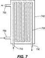
【0092】
図7の管状フィルタでは、汚染液の流路は、入口710から出口730まで延びている1つの非分割流路720である。しかしながら、この流路720は、反転ベンドで多数回前後方向にジグザグ状に構成されている。きれいに濾過された液体はハウジング740内に収集されかつハウジング740の境界を貫通する入口ポート750、出口ポート760のいずれか一方または両方を通って引き出される。洗浄すべき表面は、入口から出口に至る通路の内面である。
【0093】
図8に示すように、濾過、限外濾過および逆浸透に使用される、螺旋巻き型膜フィルタと呼ばれる他のフィルタ構造がある。この場合、2枚の矩形膜シート810、812が多孔質構造層820により分離されかつ3つの縁部830、832、834に沿って互いにシールされて、ポケットすなわち膜組立体870を形成している。チューブセクション880には、そのほぼ全長に沿う線上に小孔882が形成されている。任意であるが、チューブ880の一端は閉鎖できる。膜組立体870は、小孔882が2枚の膜シート810、812により形成されたポケットの内部に露出されるようにして、漏洩防止態様でチューブ880に取り付けられる。膜組立体870は、次に螺旋態様でチューブ880の回りに巻かれ、スペーサ890が巻回層を分離する。図8は1つの膜組立体870のみを示すものであるが、1つ以上(12個まで)のこのような膜組立体を用いてフィルタを構成できる。
【0094】
好ましくは、チューブ880への多くの膜組立体870の結合部は、チューブ880の外周面の回りで均一間隔を隔てて配置される。一般にスペーサ890は、膜シート810、812と同じ全体的寸法を有する粗いメッシュであり、チャンネルを設けることができる。スペーサ890は汚染液体流路を形成し、汚染液が膜シート810、812の殆ど全表面と接触できるようにしている。次に、このロール状組立体の全体が、ハウジング840の内部に配置される。汚染液は、ハウジング840の内部の膜組立体870の外面に供給される。汚染液の流れの供給および排出を行なうための、ハウジング840に連結された2つのポート850、860が設けられている。
【0095】
透過液は、膜を通って、膜シート810、812を分離する多孔質構造層820内に流入する。透過液は、濾過された液体を収集する中央チューブ880に到達するまで、螺旋経路の構造層820を通って移動する。この例では、汚染液は、膜とハウジング840との間で、膜組立体870の外側に供給される。浄化された液体は、中央チューブ880を通って引き出される。汚染物質は、汚染液に曝される膜810、812の全表面上に蓄積する。フィルタ組立体の適正作動を確保するため、露出膜の表面は周期的に洗浄しなくてはならない。これらの表面は、アクセスできないことおよび流速が制限されることから洗浄が困難である。しかしながら、本発明の方法は、このようなフィルタの洗浄に良く適している。
【0096】
本発明の方法により洗浄できる他の構造は、流路がハニカム(蜂の巣)におけるような多くの平行流路に分けられていて、通路の境界の両側に同じ流体の流れが存在する構造である。このような構造はセラミックで作ることができ、かつ本発明の方法により洗浄できる。
本発明を下記の例で更に詳細に説明する。しかしながら、本発明はここに説明する詳細に限定されるものではない。下記例において、水は蒸留水である。
【0097】
例1
この例は、複雑な内部構造を有する歯科ハンドピースの洗浄を示す。戻り流路が角度間隔を隔てて多数に細分されている点を除き、ハンドピースを通る流体の流路が図4に概略的に示されている。チューブの内径は、1/32〜1/16インチまで変化する。チューブは、実験の間で完全に洗浄される。
ハンドピースには、洗浄にとって最悪部位であると実験的に知られている4つの選択部位間に分散された4×10⁶個の高温菌芽胞(Bacillus
steariothermopholia spores:ATCC 7953)の初期バクテリア負荷が接種される。
【0098】
次に、ハンドピースには下記の種々の洗浄技術が適用された。次に、洗浄されたハンドピースが無菌成長媒体内に置かれ、2日間培養された。次に、バクテリア成長を測定した。
【0099】
パートA .(界面活性剤のみ)
洗浄溶液は、VWR Scientific社から入手できる界面活性剤CPC-718であり、これは、両性界面活性剤とアニオン界面活性剤との混合物である。溶液は、水により10体積%まで希釈された。この溶液は、55℃の温度で10.5のpHでを有する。80psigの圧力の空気が15秒間ハンドピースに通され、かつ空気と溶液との2相流が5分間通され、次に、水により1分間2相すすぎを行なった。2日後に、バクテリア成長は全く見られなかった。
【0100】
パートB .(過酸化物。界面活性剤は用いない)
酸化反応でのラジカル発生効率を改善する3%過酸化水素および遷移金属有機錯体の混合物が使用された点を除き、パートAの方法が続けられた。この溶液は10.4のpHおよび45℃の温度を有する。ハンドピースには、80psigの圧力の空気が15秒間通され、空気と上記溶液との2相混合物が3分間通された後、2相水によるすすぎを行なった。2日後成形に、バクテリア成長は全く見られなかった。
【0101】
パートC .
この試験には、複雑な内部構造を含んだStar Dental社の製造に係る歯科ハンドピースを使用した。ここに報告する洗浄は、図4に示した空気流路と同じ原理の、駆動空気+チップ空気+出口空気回路により形成される流路について行なった。流路の取入れ部分の構造はタービンおよびチップ空気放出に通じる簡単なチューブであり、流路の出口部分の構造はタービンからの空気戻り路である。しかしながら、出口流路440は角度方向に間隔を隔てて細分された多数の環状体である点で、図4に示した構造とは僅かに異なっている。
【0102】
例2
例1の方法を反復して、簡単な管状通路である、歯科ハンドピースの内部水ラインチャンネルを洗浄した。同様な結果が得られた。
【0103】
例3
この例には、0.084インチの外径をもつ、ポリマー被覆されたシース内のケーブルを収容した生検器具を使用した。ケーブルとシースとの間の領域を洗浄するための流体の流れへのアクセスは、存在するクリアランスを使用してケーブルがシースに出入りする、シースの各端部で行なった。シースとケーブルとの間の洗浄は、流れの源を、生検器具のオペレータ側の既存のねじ連結部に連結することにより試験した。流れは、次に、組織除去ブレードが配置された生検器具の他端部から排出された。
生検器具の外面を洗浄するため、器具の全長を、器具の外面に沿って流れを指向させる通路として機能する透明プラスチックチューブ内に挿入した。透明プラスチックチューブの内径は、生検器具の外径より約50%大きい。
空気は、硫酸ドデシルナトリウム界面活性剤水溶液を使用して、50psiの圧力および数百:1のガス:液体の流量比で供給された。両場合において、得られた流れ特性から、視覚観察で判断して良好な洗浄が得られた。
【0104】
例4
各々が1.1mmの内径をもつ約300本の中空繊維を備えた限外濾過フィルタを、本発明の混合相洗浄方法を用いて洗浄した。フィルタカートリッジの長さは約7インチである。膜の材質は、約100,000の最大分子量をもつポリスルホンである。カートリッジは、25psiの作動圧力で202ml/分(ミリリットル/分))の透過流量で作動するように設計された。中空繊維の内面は、Bovine Serum Albumin(牛の血清アルブミン)と、塩化カルシウムと、塩化マグネシウムとの混合物で汚損されている。
【0105】
汚損(ファウリング)は、透過流量がその初期流束の1/2に低下するまで続けられた。繊維は、両性界面活性剤の水溶液を用いて、15psigの空気圧力で2分間洗浄された。膜の流束はその初期値まで戻された。
上記手順は、膜が非イオン界面活性剤の溶液の単相流を30分間使用して洗浄される点を除き反復された。透過性膜は、134ml/分(ミリリットル/分)の流量すなわちその初期値の僅かに55%回復されたに過ぎない。
【0106】
手順は、0.25%の硫酸ドデシルナトリウムを含有する水溶液の単相流を60分間使用して膜が洗浄される点を除き反復された。しかしながら、透過性膜は、その初期値より小さい流量で安定した。
繊維の内面を通る流れのレイノルズ数は、空気流の既知の流量および断面積、繊維直径および空気粘度に基いて計算される。計算されたレイノルズ数は、層流の範囲内の約500〜1000の範囲内にある。洗浄作用はガス流が乱流である場合に最高であると考えられるが、このことは、層流範囲の上限でも中空繊維の限外濾過カートリッジの有効な洗浄を達成できることを示している。
【0107】
例5
パートA
図4で使用したのと同形式のフィルタの中空繊維の外面に汚染液体が供給される。汚染液体はゼラチンと染料との混合物である。洗浄溶液は、炭酸ナトリウムおよび界面活性剤「Tergitol」(Union Carbide Corporationの商標)を含有している。空気/液体比は約100:1で比較的ウェットなものであり、空気圧力は30psigであった。中空繊維はかなりの可撓性を有し、濡れると一体に凝集して洗浄を妨げる。かくして、流れは脈動し、幾分長時間運転した。優れた洗浄が達成された。
【0108】
パートB
繊維の周囲に実際のハウジングが全く存在しないときには同じ構造すなわち一群の中空繊維の外面の洗浄が行なわれ、このとき繊維は、相互の構造的連結部を有する2つのヘッダ間の開空間を単に横断しているに過ぎない。通常の使用中に、一群の繊維は汚染の可能性のある水の本体中に浸漬され、きれいな液体が繊維の内面から吸引により引き出される。混合相流を中空繊維の外面に指向させることにより洗浄が遂行される。この場合、混合相流と同時に超音波を供給するのが有効であることも判明している。
【0109】
例6
約6フィートの長さをもつ個々のチューブを8個直列に連結した、図7のかなり長い管状フィルタ(従ってチューブ内の全流れ長さは48フィートである)であって、全部で7つの180°の戻りベンドを備えた流路を有する管状フィルタが、廃水処理作業中の限外濾過フィルタとして使用された。尚、このような管状フィルタは、Zenon Environmental Co.社(カリフォルニア州、Burlington,
Ontario)から入手できる。管状膜はZenon MT-100であり、該膜は最大約100,000の分子量を有している。チューブの内径は約0.8インチである。
【0110】
廃水がこのチューブの内面に供給され、かつきれいな水が外面から抽出された。洗浄中、空気供給圧力範囲は40〜80psigであった。空気の流量は、120標準ft3/分である。空気の速度は、入口近くの約40m/秒から出口近くの約175m/秒の範囲で計算された。これらのチューブ内の空気流のレイノルズ数は225,000であった。流れ態様は膜流または薄い泡流であった。このフィルタの構造は、強いバックフラッシングができない構造である。
【0111】
パートA
フィルタは、その流束がその製造時の値の39%に低下するまで、調整された合成廃水により処理された。次にフィルタは、酸性洗浄液およびアルカリ性洗浄液の両者を含む幾つかの段階を用いて、2相洗浄法により洗浄された。硫酸ドデシルナトリウムの界面活性剤濃度は1%であった。200:1の空気:液体比および3分間のアルカリ性界面活性剤を使用したところ、流束はその初期値の64%に回復した。更に2相流を2分間供給したところ、流束はその初期値の81%に改善された。過酸化水素および遷移金属触媒を用いて更に洗浄しても、流束はこれ以上改善されなかった。2相流を反転させたところ、流束値に極く僅かな改善が見られた。
【0112】
これらの結果は、2相流を用いる管状フィルタの全部で5分間の洗浄は、流束値を回復させる上で充分であり、かつ非常に長時間を要する慣用洗浄技術と有利に比較できるものであることを示している。上記洗浄の反復により同様な結果が得られる。この実験はまた、鋭い方向変化後の混合相流状態の再形成を示している。各戻りベンドでは、混合相流状態に小滴の合体のような幾分かの乱れが生じる可能性を期待できるが、具合良い洗浄結果は、ベンドのような流れの不規則性が生じた後には混合相流状態の迅速再形成がなされることを証明している。
【0113】
パートB
他の実験では、同形式のフィルタの流束レベルがその初期値の35%に低下する状態まで、同形式のフィルタが調整された廃水により汚損された。調整された廃水を用いて流束を簡単に測定するのと同時に、洗浄が遂行されかつ次に停止された。洗浄が再開され、更なる改善が見られないことが明白になるまで、洗浄が数回反復された。このような洗浄の3つのインターバルが経過した後、全ての同じ混合相流状態で、流束レベルはベースラインの約74%のプラトーに到達し、更なる改善は得られなかった。更なる改善を得るには、管状膜の表面および多孔質構造の両者が汚損されているのでソーキングが開始された。一定期間の間、通路は静止している泡で充満され、かつフィルタの通常作動と同じ方向に圧力が加え続けられた。これにより、洗浄溶液が微孔内により深く到達することが可能になる。この保持/ソーキングサイクルは2分間続けられ、次いで、新たに入り込んだ残留物を除去するため2相流が15秒間付与された。ソーキングにより、ベースライン値の95%まで更に改善された。
【0114】
パートC
他の3つのフィルタを洗浄した。これらのうちの2つは、流束がその初期値の約40%になるまで、通常の使用により汚損され、1つは、流束がその初期値の僅かに4%となるまで通常の使用により汚損された。3つの全てのフィルタは、両性界面活性剤および12.8のpHをもつ水酸化カリウムの溶液で洗浄された。洗浄サイクルは、2相流の数分間および保持期間を有し、内部圧力は静圧状態下にある。次に、透過液側で数psiに加圧された液体洗浄溶液を用いて軽くバックフラッシングを行なった。
最も酷く汚損されたフィルタでは、酸性2相流洗浄を3分間使用して更に処理を行ない、次いでアルカリ性2相流洗浄を3分間行なった。最初の2つのフィルタはこれらの初期流束の本質的に100%まで回復し、後の1つはその初期特定流束の約95%まで回復した。
【0115】
例7
一般的な血液透析器であるFresenius Co.社(ドイツ国、Bad Homburg)の製造に係るModel 80B血液透析器を使用した。中空繊維の内径は0.2mm、各繊維の長さ/直径比は1100である。15,000本の平行中空繊維は、ポリスルホンで作られている。実験は、人の患者に使用されている血液透析器を用いて、血液透析器の全内部体積(全セル体積、Total Cell Volume: TCV)に基いた再使用条件を満たさなくなるまで、各使用後に慣用技術により再処理を行うことにより遂行された。血液透析器は、次に、混合相洗浄法を用いて再処理された。空気:液体の混合比は約200:1であり、洗浄溶液は界面活性剤およびオキシダントを含んだものである。ガス源の圧力は55psigであり、流量は、どれほどの混合相混合物が0.156インチの入口ポートおよび出口ポート(これらの端キャップは付けられたままである)を通り得るかにより決定された。混合相流による処理時間は約10分間であった。
【0116】
この結果から、SEM試験および実際のTCV測定値により示されるように、中空繊維の内孔から、タンパク質、血液細胞および構成要素を効率的に除去できた。改善は、洗浄後の血液透析器の端キャップまたはヘッダ領域の状態に視覚観察された。慣用洗浄後では、ヘッダ領域において血液の痕跡を頻繁に見ることができた。2相流による洗浄後では、このような血液の痕跡は全く残っていなかった。
中空繊維内の流れのレイノルズ数は、空気流の既知の流量および断面積、繊維直径および空気速度に基いて計算できる。計算されたレイノルズ数は約200、すなわち層流の範囲内にある。層流範囲内にあっても、ガス流が乱流であるときに洗浄作用は最高になり、血液透析器カートリッジの有効洗浄が行なえると考えられる。大きい小滴衝撃力を得るために達成可能なガス速度はかなり低いけれども、液体層から小滴を剥離するプロセスにより、微孔構造内または露出表面上に堆積した生物学的物質に力が加えられ、これらの物質の除去を補助すると考えられる。
【0117】
例8
炭酸水素ナトリウムを含む水性洗浄液を透析物側に導入することにより血液透析器を洗浄した。同時に、酢酸を含む溶液を、混合相流の形態で導入した。膜表面の近くで両液体が一体化されると、反応して泡の形態の二酸化炭素を放出する。視覚により良好な洗浄が観察された。
【0118】
例9
血液透析器は、透析物側に炭酸水の加圧溶液を充満することにより洗浄された。炭酸水が透析物側から内孔側へと膜を通って流れるときに生じる圧力降下によって、二酸化炭素の泡が溶液から発生する。良好な洗浄作用が視覚により観察された。
【0119】
例10
血液透析器は、次亜塩素酸ナトリウム(NaOCl)を含む洗浄溶液で洗浄された。0.25%のNaOClを含む2相洗浄溶液は、10分間で良好な洗浄効果を呈した.洗浄溶液が透析物側にポンプで圧送されかつ乾燥空気が中空繊維の内面に供給され、微孔を通る液体のバックフラッシングおよび中空繊維内の2相気/液流が形成された。この場合、使用すべく用意された洗浄溶液は界面活性剤を全く含んでおらず、シェーキングされたときに石鹸泡は全く発生されなかった。
【0120】
しかしながら、洗浄液が血液透析器を出て収集されると、収集容器中には多くの泡が見られた。従って、NaOClと血液透析器の微孔内に堆積した有機物質との間に何らかの化学反応が生じ、これにより石鹸のような物質が形成(鹸化)されて、これが収集容器中に泡を発生させたと考えられる。また、これらの石鹸のような物質は、膜の微孔からの他のタンパク質物質の可溶化および除去を一層補助すると考えられる。また、NaOCl溶液のアルカリ度は洗浄の値であるとも考えられる。血液透析器の全セル体積は、本質的にその初期値に回復された。
【0121】
完全なすすぎまたはフラッシングの後、洗浄段階には、過酢酸/過酸化水素混合物のような殺菌剤/滅菌剤を用いる殺菌段階が続けられる。洗浄溶液は、タンパク質を変性させる温度より低い温度の約130°Fまで暖めることができる。洗浄溶液は、これが血液透析器に供給される直前に暖めるのが好ましい。ポンプの作動特性により生じる液体流の何らかの脈動も有効である。ガス流の脈動およびリファーサル(refersal)も有効である。
【0122】
上記例はNaOClと有機物質とが相互作用して界面活性剤のような物質または効果を呈する可能性を説明したものであるが、洗浄液に既知の界面活性剤を添加することも望ましい。1つの適当な界面活性剤として、優れた性能が得られるTriton-X-100がある。この非イオン洗剤は、タンパク質を変性させることなく溶解するのに、生化学の用途でしばしば使用されている。
【0123】
同様な特性をもつ他の界面活性剤として、BASF社の製造に係るCremophor EL、エトキシルキャスタオイルおよびこれと同じ属の他の製品がある。この製品は、血液透析器を用いる患者が曝されるよりも遥かに多い量で、元の薬剤分配に既に使用されている。抗癌剤パクリタクセルの乳化および分配を行なうのに、発光ELが使用されている。洗浄液中のこれらのどの界面活性剤も、その適当な濃度は200ppmである。
NaOClを含む洗浄溶液は、界面活性剤を含有しているか否かに係わらず、NaOHにより11.3のpHまで滴定される。
【0124】
この洗浄プロセスの間、数インチの長さの凝血繊維が、混合相流と一緒に血液透析器の中空繊維から出ることが分るであろう。特にポリスルホン透析器は、これらがNaOClに曝される濃度と時間との組合せに制限を有する。しかしながら、130°Fに暖められた濃度0.225%NaOClの洗浄液で約10分間洗浄を行なうことにより、良好な洗浄が達成された。数秒毎の脈動またはオン/オプ流、および場合によっては中空繊維を通る空気の流れ方向の反転も採用された。TCVは、これらの初期値まで回復された。
【0125】
例11
この例には、Dow Chemical Co.の子会社であるFilmTec Corp.の製造に係る螺旋巻き型逆浸透フィルタ(モデル番号:TW30-1812-50)が使用された。このフィルタは10.5インチの軸線方向長さを有しかつ14回巻回された膜を有している。この膜は、水分子は通すが大きい分子は通さない微孔サイズを有している。浄水(透過液)は中央チューブを通して抽出され、一方、汚染流体は、フィルタの各端部に1つずつ設けられた2つのポート(一方のポートは、濃縮汚染水の入口として、他方のポートは出口として使用される)を通してフィルタに供給される。流束の測定は30、50および70psiの差圧で行なわれた。フィルタが新しいときは、膜を通る純水の流束は、30psiで38.6mL/分、50psiで86.4mL/分および70psiで133mL/分であった。全ての場合において、膜の上流側には、約2300〜2800mL/分の流量が維持され、これは、いつでも、濾過水の流束の少なくとも17倍の大きさであった。
【0126】
膜は、牛の血清アルブミン(Bovine Serum Albumin:BSA)、NaClおよび乾燥ミルク、石鹸、ゼラチンおよび澱粉を含んだ懸濁固体粒子を有する合成混合物で意図的に処理された。この混合物は、逆浸透膜を汚損する3つの主要な機構すなわち無機スケール、沈泥およびバイオ汚染の各々を代表する成分を含有している。この混合物は、60psigの圧力で、高圧側から2時間に亘ってポンプ圧送された。これにより、膜流束は、30psiで13.2mL/分、50psiで48.8mL/分および70psiで79.4mL/分に低下された。これらの結果は、1つの圧力と他の圧力とで幾分異なっているが、これらの流束および平均の殆どは、それぞれのベースライン流束値の50〜60%の範囲に低下される。
【0127】
幾つかの慣用洗浄シーケンスは、フィルタの汚染液体側を通ってポンプ圧送される液相のみ(水および添加物)で行なわれる。
フィルタは、0.5%の非イオン界面活性剤の溶液を用いて、50psiで25分間洗浄された。流束は、30psiで26mL/分、50psiで55mL/分および70psiで96.3mL/分まで幾分回復され、これは、これらの初期値の約68%である。
【0128】
アニオン界面活性剤(0.2%硫酸ドデシルナトリウム)を使用して、50psiで25分間洗浄する手順を反復しても、流束は、30psiで19.2mL/分、50psiで53.4mL/分および70psiで89.8mL/分であり、このことは、これ以上の改善は見られないことを示している。
ホスホン酸およびクエン酸および非イオン界面活性剤を用いて洗浄を続けたが、この場合も更なる改善は見られなかった。
【0129】
次に、NaOHおよび両性界面活性剤および非イオン界面活性剤の溶液を用いて25分間洗浄を続けたが、流束は初期値の約2/3に維持された。
次に、本発明の混合相混合物を用いて3分間洗浄を続けた。液体は、汚染水ポート一方のポートから入りかつ他方のポートから出る65psiの圧力下の空気と一緒の、水、EDTAおよび両性界面活性剤、アニオン界面活性剤および非イオン界面活性剤緩アルカリ水溶液(pH10.5)である。幾分かの改善が見られた。
【0130】
混合相洗浄は、高い空気流束(空気速度は約30〜40m/秒)で反復された。3分後に、フィルタ流束はその元の値に回復した。これは、慣用洗浄法に比べて大きな改善である。
例12
バイオ膜が成長している約2mmの内径をもつ透明プラスチックチューブを、過酸化水素水溶液およびガスを用いて、60psigの供給圧力で洗浄した。バイオ膜の完全除去が達成された。
【0131】
これに対し、60psiの混合相混合物を3分間チューブ内に通した。液体は、Dow Chemical Co.の3%のDowfax 9380(非イオン界面活性剤)、0.3%のF127非イオン界面活性剤、0.3%のTween 20非イオン界面活性剤、および1%の炭酸ナトリウム水溶液を含む溶液である。この混合物は発泡したため、チューブを通る流れが殆ど生じることがなく、洗浄は全く行なわれなかった。
【0132】
他の0.2%ヒドロキシプロピルセルロース水溶液を使用した。しかしながら、この溶液の粘度は約500cpで、水の500倍大きく、小滴の形成が妨げられる。従って洗浄は全く行なわれなかった。
混合相流を形成するのに水のみを使用した。この場合、水は高い表面張力を有するので、ガス流に追随できる小さい水滴に破砕されない。かくして、この洗浄により得られたのは、バクテリア数の僅かな減少だけである。しかしながら、軽く付着した残屑を多孔質膜表面から除去すべきときには、水のみを用いた洗浄は有効である。
Dupont Performance Chemicals の製造に係るZonyl FSPすなわちフルオロ界面活性剤の水溶液も試みた。この溶液は、通常の洗剤の表面張力よりも小さい25〜40ダイン/cmの表面張力を有する。この小さい表面張力では、形成される小滴が小さ過ぎてチューブ壁と相互作用しないため、洗浄効果は乏しいものであった。
【0133】
かくして、本発明の混合相洗浄法は、プラスチック、金属、セラミック等を含むあらゆる種類の中実通路の境界に適用できる。本発明の方法は、ガス(小泡、泡)中に分散した小滴の態様および石鹸泡のような多数の膜に似た膜流の態様を有している。多相流体力学の経験的性質のため、および所望の洗浄量および使用時間による条件変化のため、良好な洗浄のためのパラメータスペースの正確な境界を定めるのは困難である。一般に、液体が添加されるときのガス流量は、液体が全く添加されないときのガス流量の少なくとも40%である。一般に、60〜100psiの供給空気圧が有効であるが、或る目的には、コンプレッサではなくブロワでも得られる15psiほどの低い供給圧力を使用できる。
【0134】
洗浄溶液を微孔内に強制供給するか、または汚染物質を微孔から強制的に排除すべく洗浄溶液を逆方向に強制供給するかの如何に係わらず、種々の洗浄溶液、温度、脈動流、ソーキング、溶液の連続供給を使用できることは明白であろう。液体中には、溶解性または非溶解性の固体粒子を添加することもできる。水による最終すすぎを使用でき、或いは乾燥を促進するためアルコール/水すすぎを使用することもできる。本発明の範囲は開示された範囲に限定されるものではなく、特許請求の範囲の記載によってのみ定められるものである。
【図面の簡単な説明】
【図1】 水平方向の2相流体の流れ態様マップを示す図面である。
【図2】 本発明の方法により洗浄できる環状構造を示す図面である。
【図3A】 本発明の方法により洗浄できる生検器具の一構造を示す図面である。
【図3B】 本発明の方法により洗浄できる生検器具の他の構造を示す図面である。
【図4】 本発明の方法により洗浄できる歯科ハンドピースを示す図面である。
【図5】 本発明の方法により洗浄できる種々の器具のシェル/チューブ構造を示す図面である。
【図6】 本発明の方法により洗浄できる透過性膜の表面構造を示す図面である。
【図7】 本発明の方法により洗浄できる限外濾過用の他の管状フィルタを示す図面である。
【図8】 本発明の方法により洗浄できる螺旋巻き型膜フィルタカートリッジを示す図面である。[0001]
This application is a continuation-in-part of pending US patent application Ser. No. 08 / 880,662.
[0002]
(Technical field)
The present invention uses a mixed phase cleaning solution to remove biofilms, debris, contaminants, etc. from the surface of a channel including a channel having an uneven shape or a complex shape or a channel having a permeable wall. It is related with the method of removing.
[0003]
(Background technology)
It is very difficult to clean and maintain the inner surface of a passage such as a small-diameter tube, pipe, duct, etc. that conveys fluid such as liquid, gas, slurry, or aerosol. If the flow path is long and thin or difficult to reach, it is difficult to clean the surface by conventional liquid phase flushing. This is because such long and narrow passages limit the flow rate of the liquid due to the generation of a large resistance to flow. This results in limited shear stress that assists in removing contaminants from such surfaces. For the same reason, low flow rates also limit the effectiveness of the solvent.
[0004]
Cleaning small passages can also be difficult due to the nature of certain residues. As is well known, bacteria and fungi are generated on the inner surface of the flow path for supplying water even if the water is purified. Bacteria present in the water adhere strongly to the tube surface and then grow laterally to form a membrane known as a biofilm. The biofilm has a slimy membrane tactile sensation and has both organic residues and proliferating microorganisms. Bacteria deposit certain peptide components, calcium carbonate and other substances that adhere to the passageway surface on an underlaying structural matrix with polysaccharides.
[0005]
An example of this is a dental unit water line tube that sends rinse water to the mouth of a dental patient. If no special precautions are taken, this water coming out of such a tube can reach 1 million (1 × 10⁶) Colony-forming bacterial units (CFU / ml: CFU / ml). This has been proven to be due to the surface biofilm releasing bacteria in flowing water. The American Dental Association recommends reducing the level of bacteria present in dental water supply systems to 200 CFU / ml (CFU / milliliter) or less by 2000 AD. Thus, these water lines and tubes must be periodically sterilized or cleaned to ensure that any live bacteria are removed and this biofilm is removed from the tube walls to prevent infection in the dental patient. Don't be. Also, because these biofilms are a major cause of high bacterial counts and high levels of endotoxin, removal of biofilms from the passageway is also necessary for other applications including medical, industrial and food services.
[0006]
However, removal of the biofilm from the flow path is extremely difficult, thus making surface sterilization more difficult. Biofilms adhere strongly to the channel surface, regardless of whether the channel surface is made of natural materials such as rubber or metal, or synthetic polymer materials such as polyvinyl chloride, polyethylene or polytetrafluoroethylene. . Treatment with chemical agents such as bactericides and biocidal agents kills exposed surface bacteria and reduces the contribution of the biofilm to the total number of bacteria. However, these drugs do not diffuse easily within the full thickness of the biofilm. The biofilm protects the remaining viable bacteria, which then grow rapidly. When all bacteria are killed, the biofilm structure remains as an ideal host for new bacteria to colonize and grow. Thus, these treatments are generally only partially effective and return very quickly to the original level of living bacteria. In order to remove the biofilm from the surface, in addition to the drug treatment, some mechanical action is required to generate shear stress or sufficient impact on the surface.
[0007]
In dentistry, there are applications for cleaning and sterilization of both tubes and dental handpieces. Handpieces using pneumatically driven turbines or other methods for driving drills and other components have a length of about 6 inches and are removable. The tubes and other passages in the handpiece have a length / inner diameter ratio of about 100. The most common sterilization method at present is steam high pressure sterilization (autoclaving). However, in addition to the fact that steam autoclaving does not virtually remove debris from the handpiece, this steam autoclaving process can damage the turbine and various seals in the handpiece. For example, it has been found that the operating rotational speed of a dental drill decreases with the number of sterilizations.
[0008]
An older method of cleaning dental handpieces is to flush with water or a cleaning solution. This demonstrates that non-adherent biofilms and debris are flushed from the passage, while adherent biofilms and debris such as blood and mucus are hardly or not removed. In order to obtain a large force due to liquid flushing, U.S. Pat. No. 3,625,231 to Littrell discloses the use of compressed air to pass a large amount of cleaning / conditioning fluid through the passage of the handpiece. This device uses primarily a single-phase liquid flow as a requirement to observe the transparency of the fluid expelled from the handpiece as a reference for cleaning. This method is considerably more effective than flushing with a manual syringe (syringe), but only slightly more effective than flushing with water. However, complete removal of adherent biofilms, debris and contaminants is not possible.
[0009]
It is also well known to clean instruments and handpieces by spraying water or a cleaning solution. The spray can be generated by an aerosol can or an atomizer. Although this is an effective method of dispersing the cleaning solution, it is not possible to perform complete cleaning of adherent debris. Complete cleaning occurs only when shear stress overcomes debris adhesion. In addition, an effective cleaning method is a method in which the necessary stress is reduced by weakening the adhesion between the debris and the adhesion surface. In order to ensure complete cleaning, it is necessary to overcome adhesion with a large margin. In order to prevent loose debris from shielding unloose debris, it is necessary that the entire surface be covered with shear stress and sufficient mass transfer be performed. A simple spray method cannot meet these requirements.
[0010]
It is believed that the prior art using only a few drops of liquid in total cannot provide enough liquid to the surface area of the dental handpiece tube to achieve effective re-formation of the drops. One to two drops is equal to 1/10 of 1 ml (1 milliliter). Current methods use a continuous flow of time so that the amount of liquid used for the same purpose is tens of milliliters, or about 100 times larger.
[0011]
In addition to biofilms, there are food grains, various body tissue grains, mucus, saliva, non-clots or clots or blood components, pathogens, polymer substances, etc. in the passages of various medical devices, These substances are called “debris”. It is also necessary to remove the debris from the passage where these debris exists. These debris must also be removed from passages that do not become fluid transport passages during normal use of the instrument, such as passages in which cables slide within the sheath or conduit of an endoscope or biopsy instrument. Infections resulting from the use of endoscopic equipment have been reported, and the cause has been determined to be inadequate cleaning and debris removal by conventional methods.
[0012]
Endoscopes may be provided with a passage for using the biopsy instrument as well as a passage for other purposes. Both the internal passage and the exterior surface of the endoscope must be cleaned after each use. The biopsy instrument itself also has an inner surface and an outer surface that must be kept clean. To prevent cross-infection between patients, the US Gastrointestinal Endoscopy Association guidelines for cleaning gastrointestinal and other flexible endoscope units and other bodies should include a tube for each use. A multi-step method of cleaning is specified. Immediately after use, the first mechanical cleaning with a brush and cleaning solution is performed. The tube is then rinsed with water and then sterilized using a liquid chemical sterilant such as a glutaraldehyde solution. The tube is then rinsed with sterile water and dried with blown air. However, this method is time consuming and has the problem that removal of all pathogens and other debris is inefficient and the technology varies from operator to operator.
[0013]
In devices such as heat exchangers, biofilms, algae, mineral deposits or corrosion products (the last two are called scales) need to be removed from the surface of the heat exchanger. These materials reduce the heat efficiency of the heat exchanger.
[0014]
There are also applications for cleaning fluid passages having permeable walls. A permeable or porous surface is often described as a membrane. In this application, the term “membrane” refers to the surface of any structure, most commonly a structure having a more complicated than flat or tubular shape, such as a hollow fiber filter, hemodialyzer or spiral wound filter. Is used to refer to the porosity and permeability of. Examples of applications where the fluid passage walls are permeable membranes include microfiltration, ultrafiltration, kidney dialysis, reverse osmosis and the like. In such applications, small particles of undesirable substances, large molecular weight (large molecular weight)
macromolecules), biomembranes and (in the case of hemodialyzers) remove contaminants such as adsorbed serum proteins, blood cells, cell fragments, platelets, salts and other soluble or dispersible blood components from the membrane There is a need to. All of these are included in the term “debris”. Cleaning a permeable membrane is more difficult than cleaning a solid surface. Because what is trapped by the membrane is either trapped directly on the exposed surface of the membrane or trapped within the microporous structure of the membrane, the surface within the microporous structure of the membrane is much more This is because cleaning is difficult.
[0015]
Current hemodialyzers are generally reused up to about 30 times. However, in some patients, who account for about one quarter of hemodialysis patients, the hemodialyzer clogs more quickly and can therefore only be reused 3-4 times. An excellent method of cleaning and sterilizing hemodialyzers with each use will extend the useful life of hemodialyzers, and thus the biological performance of hemodialyzers that can be economically saved and reused Can be improved. Although improved cleaning can only extend the life of these hemodialyzers currently being reused 3 or 4 times to 15 reuses, the economic savings are substantial.
[0016]
Currently, membrane filters are cleaned (including backflushing) using harsh liquid-phase chemicals and / or large amounts of hot water. Such membranes are cleaned regularly but never return to their original flux levels. This inherently results in permanent performance degradation of membrane capability.
[0017]
In all these applications and structures, better path cleaning methods are effective in removing biofilms, debris, contaminants, etc. more completely and easily. In any filtration application, an excellent cleaning method will extend the membrane life or improve the processing performance.
[0018]
For medical / dental applications, thorough cleaning is a very important first step in sterilizing or sterilizing the device. A good initial wash makes subsequent sterilization and sterilization processes easier and more effective by reducing the bioburden to be killed during sterilization or sterilization. Currently, the main sterilized forms are heat, powerful drugs and radiation. Some medical devices use materials or parts that are damaged from one or more of these treatment methods, or their use may be impractical for other reasons. Therefore, an excellent sterilization or sterilization method that can be easily performed using non-harmful drugs while maintaining a state close to the surrounding state will be widely effective in many medical and industrial applications. Thus, a method for cleaning flat and irregular surfaces and passages of various medical devices, devices that come into contact with food or drinking water or devices that require sterilization, can be performed quickly, effectively and inexpensively and can be performed at extreme temperatures, powerful drugs or Cleaning methods that do not use poisons or radiation are highly desirable.
[0019]
(Summary of Invention)
In accordance with the method of the present invention, a mixed phase flow is formed along the channel surface that generates sufficient shear or impact stress or similar conditions to remove biofilm, debris and contaminants from the channel surface. To do this, a mixture of gas and a suitable liquid, preferably a mixture containing one or more cleaning agents, is used. The detergent is typically a surfactant, but may be an oxidizer, alcohol, non-surfactant detergent or solid material, or these may be included in the surfactant. The method of the present invention can be applied to fairly complex channel structures including surfaces made of porous membranes. The method of the present invention also includes optimally changing the parameters such as the mixed phase flow, the cleaning liquid agent, the temperature, and in the case of the membrane, the direction, magnitude and sequencing of the pressure differential across the membrane.
[0020]
(Best Mode for Carrying Out the Invention)
The present invention relates to a method for cleaning various uneven surfaces and passages. In general, these surfaces and passages are long and narrow. These surfaces and passages have a complex shape and can be described by their ratio of length to width or diameter. The passages may or may not carry fluid during normal use, but can carry a mixed phase fluid flow during cleaning operations. The mixed phase flow is flowed along the surface to move and remove various materials such as biofilms, other forms of biological and non-biological debris and contaminants.
The term “biofilm” is used herein to mean a bacterial colony growing on a surface and an organic matrix material with which the bacterial colony is associated.
[0021]
In describing the present invention, it is helpful to first describe some background information about hydrodynamics, structure and chemicals. It is known that a local shear stress of about 53 Pa or more is required to remove a biofilm from a solid surface. The difficulty of removing the biofilm from the surface varies with the aging of the biofilm and the nature of the surface, and generally becomes more difficult as the biofilm ages. Further, the difficulty of removal varies depending on the specific bacteria forming the biofilm. Conventional cleaning using a steady flow of liquid solution, when performed in an elongate passage, results in a total pressure drop along the passage resulting in very low flow rates, which greatly reduces the resulting wall shear stress. Biofilms, debris or contaminants cannot be removed. On the other hand, when the same passage is cleaned using a steady flow of gas alone, the gas velocity for the same total pressure drop can be very large, but because the gas viscosity is low, sufficient wall shear stress is also obtained in this case. I can't.
[0022]
In fact, in the case of constant cross section steady flow of any incompressible single phase fluid, the achievable shear stress can be calculated from the control volume view without reference to any particular fluid properties. . For any given application, there is some restriction on the total pressure drop from one end of the passage to the other. This pressure drop is determined by the structural limitations of the passage walls or other instruments. That is, the desired total pressure drop is equal to the pressure available from a pressure source such as a typical compressor. The pressure range most readily available from the compressor is about 100 psig. The force acting on the control volume is obtained by the total pressure drop × passage cross-sectional area and also by wall shear stress × wall surface area. For a given allowable or desired pressure drop across the passage, the wall shear stress is simply determined by (pressure drop x flow cross-sectional area) divided by total wall surface area.
[0023]
For a circular tube, this is further simplified as:
τ = Δp / (4 * L / D)
Where τ is the shear stress at the wall, Δp is the pressure drop from the inlet to the outlet of the passage, and (L / D) is the length / diameter ratio of the passage. Therefore, the possibility of obtaining the desired shear stress is not based on the characteristics of the fluid, nor is it determined based on whether the fluid is a liquid or a gas. In the case of elongated tubes (tubes with large L / D), this shear stress is too small to achieve biofilm removal. Under typical conditions, using the above formula, the pressure drop would be 14.7 psi (100,000 Pa) and the L / D would be greater than 1,000. This gives an average shear stress of 25 Pa, which may be a contributing factor, but is not sufficient to remove the biofilm with this shear stress alone.
[0024]
Cleaning, sterilization and sterilization are also defined herein. Washing refers to physical removal of biofilms, debris and contaminants that generally contain bacteria and / or spores. Sterilization refers to the total number of bacteria, and more specifically, it does not necessarily require complete removal of all bacteria or spores, but refers to reducing the total number of bacteria to at least 6 decimal places. Sterilization refers to inactivating all microorganisms including bacterial spores.
The gas flow rate can be expressed in standard volume units per unit time, which is actually a mass flow rate, and is constant everywhere along the steady state flow where nothing is added or removed. Standard volume units such as standard cubic feet are defined at 1 atmosphere (absolute pressure) and 0 ° C. The gas flow rate can also be expressed in actual volume units per unit time, which is a structural quantity based on local velocity and cross-sectional area. Since the density or specific volume of the gas is determined based on the absolute pressure, this flow rate of the gas is determined based on the absolute pressure of the gas at the place where the measurement is performed. Therefore, in experiments such as the present invention, the gas flow rate in actual volume units will be different at different locations along the flow path.
[0025]
Mixed phase flow has a large volume ratio of gas to liquid and some combination of liquid properties. The advantage of a mixed phase cleaning system is that it can combine the best of both liquid and gas streams. An acceptable small total pressure drop per unit length is obtained, largely governed by the gas flow characteristics, but the liquid phase moves with the gas at a high rate. Thus, where the liquid phase interacts with the wall, there is a high velocity impact of the liquid at one location and the accompanying high local shear or impact stress.
[0026]
Droplet impact can generate local instantaneous shear stress, which is much greater than the average shear stress obtained by calculation for single phase flow. This can be achieved because the droplet velocity is close to or equal to the gas velocity. On the other hand, the shear stress or impact stress generated by the droplet is related to the viscosity and / or density of the liquid, and both the viscosity and density of the liquid are very large compared to the viscosity and density of the gas. Thus, the mixed phase flow achieves high speed without causing the best characteristics of the liquid (ie, high viscosity and high density) and the best characteristics of the gas (ie, excessive pressure drop per unit length). Ability).
[0027]
The area of the wall that is cleaned by the impact of a droplet or liquid film is limited, and the area of the wall that is cleaned at any given moment is only a fraction of the total wall surface area. However, if this working method is continued for an appropriate time, due to the random nature of the working method as a whole, eventually all the bits of the entire surface are cleaned at some point under very high shear stress. The Individual portions of the surface are subjected to very large shear stresses for a short time that can remove biofilm, debris and contaminants, instead of continuous shear stress that is too small to remove biofilm, debris and contaminants. . However, at any instant, these interactions only affect a small part of the wall surface and do not cause a large total pressure drop.
By including solid particles in the liquid, the cleaning action can be further enhanced. It is also effective to add an appropriate chemical to the cleaning solution. Most commonly, the cleaning solution is an aqueous solution, but can be other liquids. The gas is typically air, but any other gas can be used.
[0028]
In the dispersed droplet flow embodiment, when the droplets impinge on the walls of the passage, they diffuse on the walls to form a sheet or liquid layer of liquid. In the fluid flow mode desired for cleaning, the sheet of liquid on the walls or surfaces of the passageway exposed to the mixed phase flow achieves a thickness that allows the moving gas to pull the droplets away from the liquid layer. This is called Bando. Bandage is based on certain fluid properties and the formation of hydrodynamic instabilities within the liquid layer. Instability means that the liquid surface does not return to a flat surface when a distorted shape is formed on the surface of the liquid layer, but rather deforms until a droplet is formed and peeled off. This is believed to be due to the forces acting on the biofilm, debris and contaminant particles where the newly formed droplets leave when they are peeled off. This force acts to peel and remove the biofilm, debris and contaminants from the surface. The surface tension of the liquid helps generate this force as the droplet is removed from the surface.
[0029]
For example, when one side of particles such as a biofilm is almost completely wetted while the other side is relatively dry, an action of a pulling force from the dry side toward the wet side is expected. With some combination of wetting under the particles and partially drying the top of the fluid, a force acting to lift the particles off the surface is expected. Since these forces are proportional to the surface tension, this is not a reason for making the surface tension very small, and in fact the surface tension of water containing various salts is the surface of pure water. Slightly greater than tension. However, the somewhat lower surface tension compared to pure water promotes droplet formation and peeling from the liquid layer, which is good. If a surfactant is used, the surfactant often provides a beneficial cleaning effect.
[0030]
There is also an embodiment that has been found to exhibit an excellent cleaning effect when the flow is a film flow such as soap suds. As the flow moves, continuous movement, folding, stretching and regeneration of the membrane occur. If the membrane strikes the wall as it moves, an impact force similar to the impact of a droplet is likely to occur, and the membrane is either pulled away from the wall or moved away from biofilm, debris or contaminant particles When moving in the direction, it is considered that a removal force similar to the above force occurs.
[0031]
In fields such as boilers, power plants, chemical processing plants and pipelines, two-phase liquid / gas flow within tubes has been studied. Knowledge tends to be somewhat empirical. There are various names for the liquid / gas flow, for example: There are names such as bubbly (lots of foam), slug, plug (stopper), stratified (layered), annular (annular), entrained (same band), floss and mist (foam and haze), but between modes It has a somewhat vague boundary. However, two variables have emerged as most likely to determine the flow mode, and these variables are used to create a parameter map that can be used to roughly predict the area of each flow mode. . Such a map has a tendency to be identified in one flow direction, such as horizontal flow, vertical upward flow, vertical downward flow, and the like. These two main variables are the volume ratio of gas to liquid and the overall velocity.
[0032]
FIG. 1 is such a map for horizontal flow, which is a common direction in medical and other applications in which the present invention is used. Slow and small gas fraction (gas
fractions) tend to become distinct regions of the gas, i.e. foam, layer or slag, which can be described as gas dispersion in the liquid. When the gas / liquid ratio is high, the flow is not gas bubbles surrounded by the liquid, but droplets of the liquid surrounded by the gas (liquid dispersed in the gas). Also, since the velocity is relatively high, the droplets are broken and carried away from the liquid surface on the wall. An aspect of interest aimed at cleaning and sterilization is that occurring at a relatively small volume liquid fraction (ie, mostly gas on a volume basis) and at a high rate.
[0033]
In addition to mechanisms such as forces generated by surface tension, bubbles are formed in the liquid, preferably at or near the location of the particles that need to be removed. One method of forming bubbles is by dissolving a gas in a liquid and emerging from solution. Another method is a method of generating a gas by a chemical reaction.
[0034]
In the case of a dissolved gas, the effective gas is carbon dioxide because it is relatively soluble in water. However, air can also be used successfully. The solubility of the gas in water is determined based on the absolute pressure to which the solution is exposed, thus causing the gas to emerge from the solution due to the pressure drop and form bubbles. As the liquid flows through the permeable membrane, a pressure drop occurs. On the upstream side (high pressure side) of the membrane, a certain concentration of gas remains in the liquid solution. On the downstream side (low pressure side) of the membrane, a small amount of gas remains in the solution and the remaining gas emerges from the solution as bubbles. Bubbles are generated directly in the microporous structure from which debris is to be removed, thereby removing the debris. The debris functions as a nucleation site for foam formation. This is an efficient use of dissolved gas in the liquid. Two other gases that can be sufficiently dissolved in water are sulfur hexaoxide and nitrous oxide, but all gases can also be dissolved to some extent in water. When oxygen or ozone is present in the gas phase, an oxidizing or bactericidal effect occurs.
[0035]
Bubbles can also be generated from a liquid by a chemical reaction that forms carbon dioxide or some other gas. For example, sodium bicarbonate reacts with any acid such as acetic acid to form carbon dioxide. In such cases, solutions that react to form gases should not be mixed until they reach the site where foam formation is desired.
[0036]
Another method of generating bubbles is to form vapor from a liquid. When liquid is introduced into the passage to be cleaned, the liquid can be in a single phase near its saturation. In this case, as the liquid flows through the passage, the thermodynamic state changes to favor the presence of two phases, reducing the pressure. This pressure drop also serves to liberate a large amount of dissolved gas when the flow continues due to the mixed phase flow flowing along the passage, forming bubbles along the entire length of the passage. Non-continuous pressure changes such as surging can also be used.
[0037]
Although foam formation has been described above for porous membranes, this method can also be applied to the cleaning of non-porous membranes, such as passages with solid walls. The pressure drop that promotes bubble formation is usually a pressure effect caused by the flow along the main direction of the passage.
[0038]
In order to successfully perform the cleaning method according to the present invention, it is necessary to understand the mechanism of droplet formation and reformation. In the band-like droplet (mist) embodiment, droplets are formed and reformed continuously as the mixed phase flow flows along the passage. After the droplet hits or deposits on the surface of the passage, the liquid is finally withdrawn from the liquid layer to form a new droplet, and the same action is repeated. As the gas flows through the liquid layer on the flat surface within the lowest gas velocity range, the liquid surface remains essentially flat and the liquid is pulled by shear. This is shown as a laminar flow in FIG.
[0039]
At somewhat higher gas velocities, waves appear on the surface of the liquid layer as a result of gas motion. This is shown as a wave form. At higher gas velocities, the wave amplitude is sufficiently large and the surface shape becomes unstable, which is a hydrodynamic instability similar to the Rayleigh instability. This causes breakage of the droplets and the broken droplets are carried by the flowing gas. As a result, mist is generated, which is referred to as obi. This is shown in FIG. 1 in a wave + mist manner. As shown in FIG. 1, the wave + mist mode exists in the mixing speed range from about 10 m / sec to about 40 m / sec. This boundary is determined based on local conditions and fluid properties such as surface tension, viscosity, etc., but such maps are created over a range of dimensions for common fluids such as water and possibly hydrocarbons. It only shows a narrow range of fluid properties.
[0040]
In general, an annular mist mode is present at a mixing speed of about 40 m / sec or more and about 100 m / sec. Perhaps in the wave + mist mode, there is sufficient agitation to form a mist, but some liquid still collects at the bottom of the horizontal tube. There is no significant difference between the bottom of the horizontal tube and the rest of the tube wall, since there is strong agitation in the highest speed annular mist embodiment. These mist embodiments are the preferred operating region for the present invention. In these embodiments, the gas velocity is high enough to remove the droplets from the liquid layer and the velocity of the liquid droplets when moving with the gas is also high enough so that these droplets are Upon impact, biofilm, debris and contaminants can be removed or eroded.
[0041]
The cleaning method of the present invention is particularly effective because it can be applied to very long 1 / D tubes and the droplets can be reformed on a continuous basis after the first impact of the droplets with the tube wall. The ability to clean long tubes is a particularly good advantage of the present invention. This requires that the gas operate in a suitable parameter space region that allows it to repetitively form and accompany droplets due to hydrodynamic instability. In the prior art using a total of 1-2 drops of liquid, it can be considered that sufficient liquid cannot be delivered to the surface area of the dental handpiece to achieve droplet reformation. One or two drops correspond to a few tenths of 1 ml (1 milliliter). In the method of the present invention, the amount of liquid used for the same purpose corresponds to several tens of times 1 ml (1 milliliter), and about two orders of magnitude more liquid is continuously flowed for a fixed time.
[0042]
Also, some structures that can be cleaned according to the present invention have abrupt shape changes, such as right angle elbows or U bends. In such a direction change portion, many droplets collide with the elbow or the bend, and therefore, there is a risk that the droplets, which are virtual corrosion mechanisms, gather. Nevertheless, the method of the present invention later demonstrates that excellent cleaning performance was observed even in passages with as many as seven turning sections. This indicates that proper mixed phase flow conditions are reestablished very successfully within a short distance after such turbulence.
[0043]
Droplet formation and reformation are affected by, among other parameters, the surface tension of the liquid, the viscosity of the liquid and the gas velocity for the liquid layer on the wall. With regard to the surface tension, it is considered important that the liquid has a surface tension that is less than the surface tension of pure water (about 72 dynes / cm), especially for small diameter tubes. When a general surfactant is added, the surface tension value can be reduced to a low value of about 17 dynes / cm based on the specific surfactant added and its concentration. It is believed that a surface tension of less than about 72 dynes / cm but greater than about 17 dynes / cm can activate the formation of suitably small droplet sizes. Such a size is thought to generate high local shear stress when a droplet moving at or near the gas velocity in the main direction of movement contacts the stationary wall and causes a viscous shear action on the wall. . Such values of surface tension will also enlarge the shear region by increasing the wetting of the wall and are believed to re-create the droplets after the first impact with the wall. However, if the surface tension is quite large and the diameter of the passage is small, the slag will form an aspect that does not achieve good cleaning (see FIG. 1).
[0044]
It is something that a surfactant achieves a surface tension greater than that of pure water (a surface tension as high as 150 dynes / cm), which is favorable for one particle removal mechanism. Has been discussed. The surface tension most often used to compare with the above values is not the static surface tension, but is considered to be the dynamic surface tension of the liquid in the time scale characteristics of the droplet formation process. Some materials cannot distinguish between static and dynamic surface tensions, while other materials have different surface tensions.
The cleaning solution can be used without the addition of a surfactant and provides a surface tension within the above parameters.
[0045]
A very low surface tension is undesirable because the droplets become too small. In such a case, the droplets completely follow the movement of the gas and rarely collide with the surface of the passage to be cleaned. This effect is called flow channelization. Thus, an amount of surfactant is added that provides excellent cleaning by satisfying the conditions of droplet re-formation and following gas motion to a degree that is not too severe.
[0046]
The viscosity of the liquid is also important. The viscosity of water is affected by the additive, and most additives act to increase the viscosity. If the viscosity of the liquid becomes too high, the liquid will be prevented from breaking into sufficiently small droplets and will remain attached to the wall after the first impact, reducing the cleaning effect. The inventor has found that the viscosity of 500 centipoise (cp) is too high.
[0047]
To achieve cleaning, the volume ratio of gas to liquid is also important. As will be described below, the general ratio of gas (usually air) to liquid cleaning solution is 50: 1 to 6000: 1, which is at normal conditions, ie 1 atmosphere (absolute pressure) and 0 ° C. The gas flow rate is considered to be the volume flow rate of the liquid solution. If the amount of liquid is too large, a slag flow profile occurs, it is difficult to achieve a sufficiently high velocity and droplet formation, and the droplets are detached from the liquid layer on the wall. If there is too little liquid, good cleaning cannot be achieved in a reasonable amount of time, simply because there are not enough droplets to impact the wall. This is solved by extending the processing time at the expense of convenience. For a given source pressure, the gas flow rate can be measured when only gas flows through the surface to be cleaned. At the same source pressure, the gas flow rate of the mixed phase flow is measured by placing a flow meter upstream of the mixing location. In general, it has been found that as a condition for excellent cleaning, the mixed gas flow rate is at least 40% of the flow rate of the dry gas alone.
[0048]
Since the liquid droplet velocity is higher near the exit than near the entrance to the passage, the cleaning effect is usually better near the exit and is somewhat less efficient near the entrance. This is because the cleaning effect is influenced in particular by the speed of the droplets, the effect of droplet reformation and the shearing of the gas stream itself.
[0049]
It is thought that the turbulent flow is more effective for the main flow of gas. Gas turbulence facilitates on-going remodeling of liquid droplets, and droplet impact on the wall is a random turbulence with local velocity (velocity component perpendicular to the wall that directs the droplet to the wall) Promoted by flow fluctuations. In general, single-phase fluid turbulence occurs at a Reynolds number of about 2000 to 3000 or more. In the present invention, since the volume fraction of the liquid is quite small, the presence of turbulent flow can be estimated by the Reynolds number of the gas flow. There are several examples where it is unlikely that the Reynolds number of the gas in the turbulent range will be achieved due to the small diameter or characteristic dimension of the passage to be cleaned. This is true for example for hemodialyzers and other hollow fiber filters. In these cases, it has been observed that satisfactory cleaning can be achieved even with a Reynolds number of several hundred. This is where turbulence is effective, but the most important conditions are probably the proper gas / liquid ratio and the sufficient velocity of the gas combined with the appropriate agent.
[0050]
In this case, this rate is still much greater than that achievable with water or a similar liquid alone, so a high gas velocity or Reynolds number that can reasonably be achieved is desirable. For small Reynolds number flows, the droplets interact with non-straight passage walls. That is, at small passage diameters, the droplets occupy a large portion of the passage diameter and simply reach the surface for size reasons. Also, even if the overall flow is laminar, the use of unsteady flow conditions caused by pulsating flow or the like could still cause effective local velocity fluctuations at the inlet.
[0051]
A pulsating flow is an alternating flow of strong and weak flow in a given direction, but also includes repeated stopping of the flow or reversal of the flow direction. Such turbulence, irregularity or unsteadiness can cause fluctuations in the gas flow, which can be effective in causing local secondary or unsteady flows that cause the droplets to interact with the surface to be cleaned. is there. Droplets that interact with the surface should provide the shear stress necessary to thoroughly clean the surface, as long as the droplets have a reasonable speed and size. Also, in such situations, a significant degree of debris removal is achieved by peeling the droplets from the liquid layer as described above.
[0052]
The pulsating gas flow can also be completely turned on / off while no liquid is flowing. Thus, some surplus liquid accumulates on the inner surface of the passage during the off-time of the liquid flow, and when pressure is applied again, fluid containing a large liquid fraction is accelerated rapidly, resulting in flow surging. By this surging, debris that has already been partially peeled off is washed.
[0053]
Initially, the removal rate is low during the minutes of removal of biofilm, debris and contaminants. However, the adhesion of biofilms, debris and contaminants to the surface is weakened. Eventually some biofilm, debris and contaminants begin to flake, which assists in the removal of adjacent biofilms, ie, continuous biofilms. This is especially true for clots. In particular, the traction force of the surging fluid is transmitted to the part that is still attached, and peels the attached part off the surface. In all cases, once a portion is removed, new surfaces and edges of the biofilm to be removed are exposed. That is, the mixed phase flow enters under the edge and begins to remove biofilm, debris and contaminants.
[0054]
For at least some applications, the optimal method is that the majority of the wash time is an essentially steady flow of mixed phase flow followed by the pulsating flow as part of the wash time.
In addition to the mist mode described above, the membrane flow mode is effective for cleaning. Such a stream probably does not contain any droplets, but contains many films as found in soap bubbles. The membrane flow is essentially a number of interacting membranes that are extruded through the passages, which are also called soap bubbles. When the membrane flow travels downstream through the passage, there is a membrane progression process that impinges on or is absorbed on the wall, and the stretching of the existing membrane is thought to regenerate a new membrane . In particular, if the membrane flow is pushed at a high rate, this serves to remove biofilm, debris and contaminants. Foam is a relatively dense and intrinsic membrane flow or has a relatively large apparent viscosity and generally has a small gas fraction and a large liquid fraction. If the foam has a large apparent viscosity and therefore it is difficult to push the foam through the passage at any large speed, little cleaning is performed.
[0055]
However, if the bubbles are thin enough (the liquid fraction is small compared to the gas) and can be forced through the passage at a rate effective for cleaning, essential cleaning is performed. Even if it is too dense to be effective for cleaning, it is effective for soaking. Perhaps the reason why a membrane stream or a small amount of foam is effective for washing is that the membrane or foam prevents the tendency of some flow to channel by trapping the droplets. Dense foam can be considered to resemble a shaving cream, while membrane flow or dilute foam is more preferred for the present invention.
[0056]
It will also be appreciated that by observing the mixed phase wash stream flowing through the clear plastic tube, there is not necessarily a sharp boundary between the droplet flow mode and the membrane flow or bubble mode. On the contrary, as it travels along the passage, a gradual transition state is formed in which the flow starting as a droplet becomes like a membrane flow or a bubble. The difference between the physical properties of both aspects is not always obvious. This is because there is a region where the flow is not clear in either the droplet flow mode or the membrane / bubble mode. The flow is unsteady and can vary between both embodiments. The nature of the foam is also affected by the antifoaming agent. To achieve good cleaning, conditions suitable for mist flow are used, for example, high gas velocities are still important.
[0057]
If the gas velocity cannot achieve 10 m / sec identified on the two-phase flow map as a mist flow boundary in a horizontal two-phase flow, cleaning can be done in any way. For example, when an attempt was made to perform vertical cleaning using a hemodialyzer, effective cleaning could be performed. Some structural directions can be made more tolerant of lower gas velocities than others. A successful gas velocity as low as 1 m / sec is also considered an example of cleaning that can be expected to succeed.
[0058]
Also, in the presence of local pressure fluctuations, the gas flows between the biofilm and the solid surface while at high pressure, and then expands and lifts the biofilm when the pressure drops, thereby raising the biofilm. Is peeled off. To achieve this, a pulsating flow can be supplied. In certain two laminar flow aspects, the fluid behavior is essentially unsteady, which causes certain pressure fluctuations. In addition to biofilm, debris and contaminant stripping, the overall flow carries biofilm, debris and contaminants out of the passageway by flushing.
[0059]
In addition to passing the mixed phase flow through the passage, it is useful to additionally soak the passage for a period of time in order to soften the material to be removed. In this case, the liquid or bubbles present in the passage are stationary or move very slowly. It is also effective to use a continuous operation of washing, soaking and washing again. In addition to the solid surface cleaning described above, the present invention is also applicable to microporous membranes where biomembranes, debris and contaminants can penetrate into the microporous structure and over the entire surface.
[0060]
In conventional cleaning, many porous passages are cleaned (called backflushing) by creating a pressure differential across the membrane, with the pressure on the non-contaminated side being higher than the pressure on the contaminating side. Be washed). In this method, the debris is pushed out from the back side of the micropore containing the debris to the surface side. This technique can be effectively used in the present invention with mixed phase flow, where biofilms, debris and contaminant particles are pushed out of the micropores into the mixed phase flow due to backflushing pressure differences. And then immediately removed by this mixed phase flow.
[0061]
There are other combinations of flow conditions that can be cleaned according to the present invention as long as there is a mixed phase flow on the side of the membrane that contains biofilm, debris and contaminants. For example, the membrane's lumen side containing biomembranes, debris and contaminants is exposed to a mixed phase flow, while the other side of the membrane is the same high pressure liquid or gas as previously described. Exposed to. Either liquid or gas exhibits the ability to push biofilms, debris and contaminants out of the micropores they contain. Although this method is not particularly preferred, some washing can be achieved by keeping the dialysate side of the membrane unpressurized under the same conditions as the mixed phase flow inside the inner bore.
Another useful sequence is to wash in one direction of flow, reverse the inlet and outlet, and then perform the wash procedure in the opposite direction of flow. As described above, the long tube has a higher gas velocity near the outlet, so the cleaning efficiency is somewhat higher near the outlet than near the inlet. In this way, each end of the tube will be at the outlet end for a period of time, thus providing the best cleaning. However, this increases the cleaning time.
[0062]
Other examples when washing in both directions is particularly effective are heat exchangers, hemodialysis cartridges or structures in which the structure forms a blind end and has significant irregularities due to the large number of fibers entering the end cap The shell side of a shell and tube structure like an ultrafiltration cartridge. Blind end cleaning is believed to be more effective than the reverse flow direction using a flow toward the blind end and exiting the bifurcation. The former flow generates a large turbulent flow that flows into the blind end region and rubs. Since there are two blind ends (one at each end of the device), it is probably effective to first flow in one direction and then reverse the flow to flow in the other direction. Let's go. Based on the design of the device, a connector can be designed that effectively directs flow to the blind end with respect to the blind end.
[0063]
The mixed phase wash procedure of the present invention is preferably performed using one wash solution for the first time and the other wash solution for the next time. More specifically, generally in medical practice, the first stage performs a more mechanical cleaning stage to remove the total amount of biofilm, debris and contaminants, the second stage includes chemical, thermal, etc. Carry out a more sterilizing stage. If it is desired to vary the process with respect to these steps, a more mechanical step to remove the total amount of biofilm, debris and contaminants can be achieved using mixed phase flow using the liquid wash solution. The other steps that can be performed and use a mixed phase flow are performed using a sterile cleaning solution. The latter cleaning solution can be an oxidant, biocide or alcohol. Another example when sequencing of a liquid cleaning solution is desired is when one or more debris to be removed is organic debris such as calcium carbonate and inorganic scale. An alkaline solution is preferred for organic debris, while an acidic cleaning solution is preferred for facing debris. These solutions are fed continuously.
[0064]
Finally, the liquid cleaning solution or gas or both are preferably supplied at a temperature somewhat above ambient temperature. This is because cleaning is generally performed at a high temperature. In the case of shell and tube type constructions, and more particularly in the case of small sized devices such as hemodialyzers, at high temperatures, large flow rates through the shell region may be easily maintained compared to the tube region. Thus, in addition to or instead of warming the mixed phase flow, the flow through the shell region can be warmed to warm up and maintain the entire apparatus at this temperature. The entire device can also be kept warm.
[0065]
After performing the cleaning sequence, the cleaned surface can be rinsed or flushed to remove any traces of cleaning agent added to form a liquid cleaning solution. When the liquid cleaning solution is based on water, this can be done with water or with a two-phase solution of water and gas, using a mixing ratio previously used or suitable for rinsing. Can be done. Rinsing is performed with a mixed phase flow containing pure water, and flushing is performed with any liquid flow. Finally, the procedure can include drying the passage with a drying gas. According to conventional liquid chemical sterilization or disinfection procedures, it is common to rinse with alcohol or a 70% aqueous alcohol solution following the final stage and then dry with a stream of dry air. This can be easily done with the method of the invention.
[0066]
When the adhesive force is weak, sufficiently good cleaning can be performed with a mixed phase flow containing only a gas such as water or alcohol and a pure water solution. However, significant additional benefits can be obtained by adding detergent to the liquid. Surfactants are known to penetrate into the residue to be removed and diffuse at the interface between the residue and the surface to be cleaned. This weakens the binding and adhesion forces at this interface and increases the distance between the residue and the surface (this is commonly referred to as the steric effect) and in some cases the static between them. Electrorepulsive action is increased. This action, combined with the mechanical action of the mixed phase flow, promotes faster and more efficient cleaning and removal of the residue. Accordingly, the surfactant composition of the liquid cleaning formulation is important along with the pH and oxidizing ability of the cleaning liquid. A soluble inorganic component having a surface cleaning ability can also be added. In general, surfactants have a molecular structure with a hydrophilic head and a hydrophobic tail. Surfactants used in the liquid phase include a plurality of surfactants including anionic, cationic, nonionic and amphoteric types.
[0067]
Suitable anionic surfactants include fatty acid soaps that cover an alkyl chain length range of up to about 18 carbon atoms, and may be of linear or branched alkyl groups. These surfactants are used at a pH higher than the dissociation constant of these corresponding carboxylic acids. Other classes of anionic surfactants that have been found to be effective in the method of the present invention include alkyl sulfates and sulfonates such as sodium dodecyl sulfite (SDS). Yet another effective anionic surfactant is based on alkyl polyoxyethylene sulfate. Other anionic surfactants that can be used include alkylbenzene sulfonates. Linear and branched alkyl benzene sulfates with one or more sulfonate groups have been found to be effective. Suitable anionic surfactants further include alpha olefin sulfonates, monoalkyl phosphates, acyl isothionates, acyl glutamates, N acyl sarcosinates and alkenyl succinates having anionic surface groups and surface activity. .
[0068]
Suitable amphoteric surfactants include alkyl dimethylamine oxides, alkyl carboxybetaines, alkyl sulfobetaines, amide-amino acid type amphoteric substances that exhibit amphoteric surface activity. Amphoteric substances have both acid radical and alkali group properties.
Effective nonionic surfactants include polyoxyethylene alkyl ether, polyethylene alkylphenyl ether, polyethylene fatty acid ester, sorbitan fatty acid ester, polyethylene sorbitan fatty acid ester, sugar ester of fatty acid alkyl polyglycoside, fatty acid diethanolamide, fatty acid monoglyceride, alkyl monoglyceride. Examples include seral ether and fatty acid polypropylene glycol ester.
[0069]
As cationic surfactants effective in the present invention, alkyltrimethylammonium salts having a cationic functional group and having a certain surface activity and their phosphonium analogs, dialkyldimethylammonium salts, alkylammonium salts, alkylbenzyldimethylammonium salts, alkyls Examples include pyridinium salts.
Polymer dispersants are also useful in the present invention. These do not have a general surfactant molecular structure, but have the same effect. Examples of these include formaldehyde condensate of naphthalene sulfonate, sodium acrylate or other acrylic acid copolymer, olefin and sodium maleate, lignin sulfonate, polyphosphate, silicate and polysilicate, carboxymethylcellulose, cationic cellulose, There are cationic starch, polyvinyl alcohol, polyethylene glycol, polyacrylamide and the like. These formulations are also useful in the present invention as surfactants. Also, although not strictly a surfactant, detergents are also effective, examples of which are trisodium phosphate, sodium carbonate and polymers. These materials can also be used in the present invention.
[0070]
Another factor is the degree of foaming caused by the use of surfactants. As previously mentioned, some degree of foaming is considered effective for cleaning. However, excessive foaming reduces the speed of the mixed phase flow and may almost stop the flow. Therefore, the surfactant (s) used in the liquid cleaning solution must be essentially low foaming or add antifoaming or defoaming agents to the cleaning solution. Can do. These agents are known and are commercially available.
Another important parameter of the cleaning liquid is its viscosity. This is because the liquid viscosity affects the mechanical action of the mixed phase cleaning method. In the case of an aqueous solution, the viscosity of the cleaning solution can be adjusted to increase by adding carboxymethyl cellulose, hydroxyethyl cellulose, polyacrylic acid or any other viscosity increasing agent, if desired.
[0071]
Chelating agents such as citrate, phosphate and ethylenediamide sodium salt are useful for several applications for reasons including softening of hard water and facilitating removal of inorganic scale from surfaces such as water tubes, heat exchangers and membranes .
A humectant can also be added to the formulation. The humectant is absorbed into the debris and then helps to absorb the water and loosen the debris. Suitable humectants include glycerol, sorbitol and ethylene glycol.
[0072]
The optimum pH of the cleaning solution is determined based on the nature of the material to be removed. An alkaline solution is preferred for removing organic deposits. As is known in the art, pH adjusting additives can also be used. An acidic solution is preferred for removing inorganic deposits such as scale.
An example of an effective non-surfactant aqueous solution is alcohol in water. A particularly suitable alcohol is ethanol, which is widely used as a fungicide, but has inherent toxicity. The physical properties of alcohols, especially ethanol, as surface tension and viscosity modifiers are the same as the physical properties of water. Thus, an aqueous solution of alcohol resembles water.
[0073]
A biocide or bactericidal agent such as glutaraldehyde or peracetic acid can be added to the cleaning solution. Peracetic acid is present only in equilibrium with a certain concentration of hydrogen peroxide.
Oxidizing agents can be added to the wash solution to help kill any bacteria that may not be physically removed by the mixed phase flow process. The oxidizing agent can be selected from oxygen-based or chlorine-based agents such as sodium hypochlorite or its source, hydrogen peroxide or this source and other oxidizing agents. Hydrogen peroxide can be formed from hydrogen peroxide precursors such as percarbonate and perborate while maintaining flow through the passage. As is known, a catalyst can also be used to assist the oxidation action.
[0074]
It is also possible to use ultrasound simultaneously with the mixed phase wash or at other times. Ultrasonic vibrations help loosen biofilms, debris and contaminants, particularly in connection with the cleaning action of mixed phase flows. This method is particularly suitable for washing hemodialyzers when the washing liquid fills the dialysate side. This is because the ultrasonic waves pass through the liquid on the dialysate side and reach the fibers themselves. The hemodialyzer can be immersed entirely in an ultrasonic transmission liquid bath, or the ultrasonic transducer can be brought into contact with the outer surface of the hemodialyzer by any other method known to those skilled in the art. it can.
[0075]
A particularly effective cleaning solution for the process of the present invention is an aqueous solution containing hydrogen peroxide. Hydrogen peroxide decomposes to form free oxygen, which can be used to oxidize organic materials and kill microorganisms. Therefore, hydrogen peroxide cleaning using a mixed phase flow has been found to have a superior effect on reducing the number of bacteria than cleaning using a pure water mixed phase flow. Hydrogen peroxide is not a surfactant, but when it acts on the biofilm, it chemically attacks the biofilm and reduces the adhesion of the biofilm to the surface. The loose biofilm is then drained from the system being cleaned by flushing. Another advantage of hydrogen peroxide is that there is no disposal problem since the only decomposition product other than oxygen is water.
[0076]
Solid particles can also be added to the mixed phase wash solution. The particles to be added may be either water-soluble or water-insoluble particles. Examples of suitable solid particles include water soluble sodium bicarbonate and water insoluble calcium carbonate. The solid particles impart a rubbing action in addition to the mixed phase flow. A solid oxidizing agent is effective as the solid particles.
An important advantage of the present invention is that the time required to remove biofilms, debris and contaminants is rather short and is a few minutes. This is in contrast to liquid disinfectants that soak the passageway for extended periods of time or days when the liquid disinfectant does not physically remove the biofilm structural matrix.
[0077]
Next, the present invention will be described in more detail with reference to FIGS.
The cleaning method of the present invention can be used with simple round tube structures such as water lines and endoscopes of dental units, water or fluid lines of other medical devices such as kidney dialysis devices, or non-circular shapes such as oval, rectangular or closed curves. It can be applied to complex structures such as tubes or conduits with a circular cross section. Housed within the tube or conduit is some other internal component formed by a closed curve (s). This can be an annular structure with an inner tube or object, for example as shown in FIG.
[0078]
In FIG. 2, an
[0079]
3A and 3B are cross-sectional views of
[0080]
FIG. 4 shows a
[0081]
Several different designs of handpieces are known and can also be cleaned by the method of the present invention. In some handpieces, chip air is discharged coaxially around the discharge water to break up the discharge water into a spray. Other handpieces do not divert the chip air from the turbine air supply, but have a completely separate chip air fluid path and connection. In other designs, all fluid passages are arranged coaxially at the connection between the handpiece and the instrument energy supply cord. As a result, several annular channel structures as described above are formed. In a more complex design, the return air from the turbine flows into a space that is generally annular but subdivided at annular intervals. This can also be described as a number of parallel passages, each passage having an elongated cross section. This uneven shape and cross section also require cleaning and can be cleaned using the method of the present invention.
[0082]
The method of the present invention can also be applied to the cleaning of passages provided with other two forks or branches. FIG. 5 shows a cross section of a shell / tube heat exchanger. The fluid flows through the inlet port 505 and is divided in an
[0083]
The
[0084]
Some heat exchangers are constructed using U-tubes or other structures inside the shell, and some heat exchangers have variously structured fins. The present invention is effective for cleaning a heat exchanger having any of these structures.
The device has a solid surface. An apparatus having a porous surface will be described below.
[0085]
Equipment for filtration, reverse osmosis and hemodialysis uses membranes that separate particles, substances or polymeric substances from liquids (typically water), while allowing liquids to flow through the membrane and others The substance and the polymer substance are prevented from flowing through the membrane to separate them. Membranes often have a large surface area and are tubular, but do not necessarily have a circular cross section. Under pressure, a liquid such as water flows along a fluid passage that is lined with or made entirely of a porous membrane material. Various membrane designs separate solids, bacteria, dissolved substances, viruses, etc. from drinking water, wastewater, blood, food, etc. Such a filter can be used for the purification of salty water or salt water (seawater desalination) and the recovery of suitable drinking water from wastewater.
[0086]
In addition to the exposed surface, eg, the surface that is directly exposed to the mixed phase flow during cleaning, the membrane has a microporous surface that is a narrow passage surface through the membrane. This is illustrated in FIG. 6, which shows a cross section of a permeable membrane having the shape of a tube. The
[0087]
The method of the present invention can be used to clean both the exposed
[0088]
As an example of an instrument that uses such a membrane, a hemodialyzer filter allows waste products to pass through the membrane, but removes waste products from the blood by preventing the passage of the desired components of the blood. A separation membrane is used. While hemodialyzers operate based on osmotic pressure differences, some hemodialyzers use microfiltration filters and operate based on chemical concentration differences on both sides of the permeable membrane, but pressure differences on both sides of the membrane. Is not as large as reverse osmosis and ultrafiltration. Generally, hemodialyzer structures have a plurality of hollow fibers up to about 15,000. Blood from the patient enters the interior of the hollow fiber and the headers at both ends of the hemodialyzer. Thus, the major surfaces that must be cleaned and sterilized to reuse the hemodialyzer are the hollow fibers and the inner surface of the header. The outer surface of the hollow fiber is exposed to dialysate, a fluid that absorbs and carries any waste material from the patient's blood. The hemodialyzer is used repeatedly. The micropores in the dialyzer membrane are clogged with biological material, and the cross-sections of the individual hollow fibers are blocked, resulting in poor performance.
[0089]
The main difference between heat exchangers and hemodialyzers is that the tube walls are porous and the tubes have various dimensions and ratios. As shown in FIG. 5, the hemodialyzer has a plurality of thin hollow fibers (tubes) 520 that are permeable, all of which are connected to an
[0090]
During mixed phase washing, the dialysate side fluid can be continuously circulated, but there is no need for continuous circulation. One useful function of the dialysate-side fluid is that it can be raised to a certain temperature in order to keep the entire hemodialyzer warm and maintained at that temperature. Other means of heating the hemodialyzer include means including convection, infrared radiation, preheating and the like. Of course, the mixed phase flow itself in the
[0091]
In the case of a hemodialyzer, the permeability of the membrane is such that when the dialysate side is pressurized to a higher pressure than in the hollow fiber, the amount of water or liquid that leaches through the membrane during the washing process is It is sufficient to generate a two-phase flow situation within. In this embodiment, only the flow of the dry gas can be supplied into the passage. In this case, this gas stream will be two-phase as a result of mixing with the permeate. In this case, the two-phase flow will have a high liquid content as the two-phase flow proceeds from the inlet to the outlet of the passage due to leaching of additional liquid along the passage. This variability in the liquid fraction itself is not an intended feature of this mode of operation, but is convenient.
Filtration structures such as microfiltration, ultrafiltration and reverse osmosis are the same as shells, tube heat exchangers and hemodialyzers. One difference regarding the structure of the shell / tube heat exchanger or hemodialyzer is that generally only three connections are actually used. On the side containing the purified fluid, there is only one outflow, so usually only one connecting part has to be used. The purified liquid that flows out is called the permeate.
[0092]
In the tubular filter of FIG. 7, the flow path of the contaminated liquid is one
[0093]
As shown in FIG. 8, there is another filter structure called a spiral wound membrane filter used for filtration, ultrafiltration and reverse osmosis. In this case, the two
[0094]
Preferably, the joints of
[0095]
The permeate flows through the membrane and into the
[0096]
Another structure that can be cleaned by the method of the present invention is a structure in which the flow path is divided into many parallel flow paths, such as in a honeycomb, and the same fluid flow exists on both sides of the passage boundary. Such a structure can be made of ceramic and can be cleaned by the method of the present invention.
The invention is explained in more detail in the following examples. However, the invention is not limited to the details described herein. In the following example, the water is distilled water.
[0097]
Example 1
This example illustrates cleaning of a dental handpiece having a complex internal structure. The fluid flow path through the handpiece is shown schematically in FIG. 4 except that the return flow path is subdivided into multiple pieces at angular intervals. The inner diameter of the tube varies from 1/32 to 1/16 inch. The tube is thoroughly washed between experiments.
The handpiece has 4 × 10 4 dispersed between four selected sites experimentally known to be the worst site for cleaning.6Pieces of thermophilic spore (Bacillus)
Steariothermopholia spores (ATCC 7953) is inoculated with an initial bacterial load.
[0098]
Next, the following various cleaning techniques were applied to the handpiece. The washed handpiece was then placed in a sterile growth medium and incubated for 2 days. Next, bacterial growth was measured.
[0099]
Part A .(Surfactant only)
The cleaning solution is a surfactant CPC-718 available from VWR Scientific, which is a mixture of amphoteric and anionic surfactants. The solution was diluted to 10% by volume with water. This solution has a temperature of 55 ° C. and a pH of 10.5. Air at 80 psig pressure was passed through the handpiece for 15 seconds and a two-phase flow of air and solution was passed for 5 minutes followed by a two-phase rinse with water for 1 minute. After 2 days, no bacterial growth was seen.
[0100]
Part B .(Peroxide. No surfactant used)
The method of Part A was continued except that a mixture of 3% hydrogen peroxide and a transition metal organic complex that improved the radical generation efficiency in the oxidation reaction was used. This solution has a pH of 10.4 and a temperature of 45 ° C. The handpiece was flushed with air at a pressure of 80 psig for 15 seconds, followed by a two-phase mixture of air and the solution for 3 minutes, and then rinsed with two-phase water. No bacterial growth was seen in the molding after 2 days.
[0101]
Part C .
For this test, a dental handpiece manufactured by Star Dental with a complex internal structure was used. The cleaning reported here was performed on the flow path formed by the drive air + tip air + outlet air circuit, based on the same principle as the air flow path shown in FIG. The structure of the intake section of the flow path is a simple tube that leads to turbine and tip air discharge, and the structure of the outlet section of the flow path is an air return path from the turbine. However, the
[0102]
Example 2
The method of Example 1 was repeated to clean the internal water line channel of the dental handpiece, a simple tubular passage. Similar results were obtained.
[0103]
Example 3
This example used a biopsy instrument containing a cable in a polymer-coated sheath with an outer diameter of 0.084 inches. Access to the fluid flow to clean the area between the cable and the sheath was made at each end of the sheath where the cable enters and exits the sheath using the existing clearance. Washing between the sheath and cable was tested by connecting the flow source to an existing screw connection on the operator side of the biopsy instrument. The flow was then discharged from the other end of the biopsy instrument where the tissue removal blade was placed.
In order to clean the outer surface of the biopsy instrument, the entire length of the instrument was inserted into a transparent plastic tube that served as a passage to direct flow along the outer surface of the instrument. The inner diameter of the transparent plastic tube is about 50% larger than the outer diameter of the biopsy instrument.
Air was supplied using an aqueous sodium dodecyl sulfate surfactant solution at a pressure of 50 psi and a gas: liquid flow ratio of several hundred: 1. In both cases, good flow was obtained from the obtained flow characteristics as judged by visual observation.
[0104]
Example 4
Ultrafiltration filters with about 300 hollow fibers each having an inner diameter of 1.1 mm were cleaned using the mixed phase cleaning method of the present invention. The filter cartridge is about 7 inches long. The material of the membrane is polysulfone with a maximum molecular weight of about 100,000. The cartridge was designed to operate at a permeate flow rate of 202 ml / min (milliliter / min) at an operating pressure of 25 psi. The inner surface of the hollow fiber is fouled with a mixture of Bovine Serum Albumin (bovine serum albumin), calcium chloride, and magnesium chloride.
[0105]
Staining (fouling) was continued until the permeate flow rate dropped to 1/2 of its initial flux. The fibers were washed with an aqueous solution of amphoteric surfactant for 2 minutes at 15 psig air pressure. The membrane flux was returned to its initial value.
The above procedure was repeated except that the membrane was washed using a single phase flow of a solution of non-ionic surfactant for 30 minutes. The permeable membrane was only restored at a flow rate of 134 ml / min (milliliter / min), ie only 55% of its initial value.
[0106]
The procedure was repeated except that the membrane was washed using a single phase flow of an aqueous solution containing 0.25% sodium dodecyl sulfate for 60 minutes. However, the permeable membrane was stable at a flow rate less than its initial value.
The Reynolds number of the flow through the inner surface of the fiber is calculated based on the known flow rate and cross-sectional area of the air flow, fiber diameter and air viscosity. The calculated Reynolds number is in the range of about 500 to 1000 within the laminar flow range. The cleaning action is considered best when the gas flow is turbulent, which indicates that an effective cleaning of the hollow fiber ultrafiltration cartridge can be achieved even at the upper end of the laminar flow range.
[0107]
Example 5
Part A
Contaminated liquid is supplied to the outer surface of the hollow fiber of the filter of the same type used in FIG. The contaminated liquid is a mixture of gelatin and dye. The cleaning solution contains sodium carbonate and the surfactant “Tergitol” (trademark of Union Carbide Corporation). The air / liquid ratio was about 100: 1 and was relatively wet, and the air pressure was 30 psig. The hollow fibers have considerable flexibility and when wet, they aggregate together and prevent cleaning. Thus, the flow pulsated and operated for some time. Excellent cleaning was achieved.
[0108]
Part B
When there is no actual housing around the fiber, the same structure, i.e. the outer surface of the group of hollow fibers, is cleaned, where the fiber simply traverses the open space between the two headers with mutual structural connections. I'm just doing it. During normal use, a group of fibers is immersed in a body of potentially contaminated water and clean liquid is drawn from the inner surface of the fiber by suction. Cleaning is accomplished by directing the mixed phase flow to the outer surface of the hollow fiber. In this case, it has also been found that it is effective to supply ultrasonic waves simultaneously with the mixed phase flow.
[0109]
Example 6
The fairly long tubular filter of FIG. 7 (thus the total flow length in the tube is 48 feet) with 8 individual tubes connected in series, approximately 6 feet long, for a total of 7 180 A tubular filter with a flow path with a return bend of 0 ° was used as an ultrafiltration filter during wastewater treatment operations. Such a tubular filter is manufactured by Zenon Environmental Co. (Burlington, Calif.).
Ontario). The tubular membrane is Zenon MT-100, which has a molecular weight of up to about 100,000. The inner diameter of the tube is about 0.8 inch.
[0110]
Waste water was supplied to the inner surface of the tube and clean water was extracted from the outer surface. During cleaning, the air supply pressure range was 40-80 psig. Air flow rate is 120 standard ftThree/ Min. Air velocity was calculated in the range of about 40 m / sec near the inlet to about 175 m / sec near the outlet. The Reynolds number of the air flow in these tubes was 225,000. The flow mode was a membrane flow or a thin bubble flow. This filter has a structure that does not allow strong backflushing.
[0111]
Part A
The filter was treated with conditioned synthetic wastewater until its flux dropped to 39% of its production value. The filter was then cleaned by a two-phase cleaning method using several stages including both acidic and alkaline cleaning solutions. The surfactant concentration of sodium dodecyl sulfate was 1%. Using an air: liquid ratio of 200: 1 and an alkaline surfactant for 3 minutes, the flux recovered to 64% of its initial value. Furthermore, when the two-phase flow was supplied for 2 minutes, the flux was improved to 81% of the initial value. Further washing with hydrogen peroxide and a transition metal catalyst did not improve the flux any further. When the two-phase flow was reversed, a slight improvement was observed in the flux value.
[0112]
These results show that a total of 5 minutes of cleaning of a tubular filter using a two-phase flow is sufficient to restore the flux value and can be advantageously compared to conventional cleaning techniques that require a very long time. It shows that there is. Similar results are obtained by repeated washing. This experiment also shows the reformation of the mixed phase flow state after a sharp change of direction. Each return bend can be expected to have some turbulence, such as droplet coalescence, in the mixed phase flow condition, but a good cleaning result will be obtained after a bend-like flow irregularity has occurred. Proves that rapid re-formation of the mixed-phase flow is achieved.
[0113]
Part B
In other experiments, the filter of the same type was fouled by conditioned wastewater until the flux level of the filter of the same type dropped to 35% of its initial value. At the same time that the flux was simply measured using conditioned wastewater, a wash was performed and then stopped. The wash was repeated several times until it was apparent that no further improvement was seen. After three such cleaning intervals, the flux level reached a plateau of approximately 74% of baseline at all the same mixed phase flow conditions and no further improvement was obtained. To obtain further improvements, soaking was initiated because both the surface of the tubular membrane and the porous structure were fouled. For a period of time, the passage was filled with stationary foam and pressure continued to be applied in the same direction as normal operation of the filter. This allows the cleaning solution to reach deeper into the micropores. This hold / soak cycle was continued for 2 minutes, and then a two-phase flow was applied for 15 seconds to remove the newly entrapped residue. Soaking further improved to 95% of the baseline value.
[0114]
Part C
The other three filters were washed. Two of these are fouled by normal use until the flux is about 40% of its initial value, and one is normal use until the flux is only 4% of its initial value. It was fouled by. All three filters were washed with a solution of amphoteric surfactant and potassium hydroxide having a pH of 12.8. The wash cycle has a few minutes of two-phase flow and a holding period, and the internal pressure is under static pressure. Next, light backflushing was performed using a liquid cleaning solution pressurized to several psi on the permeate side.
The most severely fouled filter was further treated using an acidic two-phase flow wash for 3 minutes, followed by an alkaline two-phase flow wash for 3 minutes. The first two filters recovered to essentially 100% of their initial flux and the latter one recovered to about 95% of its initial specific flux.
[0115]
Example 7
A Model 80B hemodialyzer manufactured by Fresenius Co. (Bad Homburg, Germany), a common hemodialyzer, was used. The inner diameter of the hollow fiber is 0.2 mm, and the length / diameter ratio of each fiber is 1100. 15,000 parallel hollow fibers are made of polysulfone. The experiment was performed after each use, using a hemodialyzer used in a human patient, until the reuse conditions based on the total internal volume of the hemodialyzer (Total Cell Volume: TCV) were not met. This was accomplished by reprocessing using conventional techniques. The hemodialyzer was then reprocessed using a mixed phase wash method. The air: liquid mixing ratio is about 200: 1, and the cleaning solution contains a surfactant and an oxidant. The pressure of the gas source was 55 psig and the flow rate was determined by how much mixed phase mixture could pass through the 0.156 inch inlet and outlet ports (these end caps remain attached). The processing time by the mixed phase flow was about 10 minutes.
[0116]
From this result, protein, blood cells and components could be efficiently removed from the hollow fiber bore as shown by SEM tests and actual TCV measurements. The improvement was visually observed in the condition of the hemodialyzer end cap or header area after washing. After routine cleaning, blood traces could often be seen in the header area. No traces of such blood remained after washing with a two-phase flow.
The Reynolds number of the flow in the hollow fiber can be calculated based on the known flow rate and cross-sectional area of the air flow, fiber diameter and air velocity. The calculated Reynolds number is about 200, ie in the range of laminar flow. Even within the laminar flow range, it is considered that the cleaning action is maximized when the gas flow is turbulent, and the hemodialyzer cartridge can be effectively cleaned. Although the achievable gas velocities to achieve large droplet impact forces are quite low, the process of peeling the droplets from the liquid layer exerts forces on biological material deposited in the microporous structure or on exposed surfaces. It is thought to assist in the removal of these substances.
[0117]
Example 8
The hemodialyzer was washed by introducing an aqueous washing solution containing sodium hydrogen carbonate into the dialysate side. At the same time, a solution containing acetic acid was introduced in the form of a mixed phase flow. When both liquids are integrated near the membrane surface, they react to release carbon dioxide in the form of bubbles. Visually good cleaning was observed.
[0118]
Example 9
The hemodialyzer was washed by filling the dialysate side with a pressurized solution of carbonated water. Carbon dioxide bubbles are generated from the solution by the pressure drop that occurs when carbonated water flows through the membrane from the dialysate side to the inner bore side. A good cleaning action was visually observed.
[0119]
Example 10
The hemodialyzer was washed with a wash solution containing sodium hypochlorite (NaOCl). The two-phase washing solution containing 0.25% NaOCl exhibited a good washing effect in 10 minutes. The wash solution was pumped to the dialysate side and dry air was supplied to the inner surface of the hollow fiber, forming a liquid backflush through the micropores and a two-phase gas / liquid flow in the hollow fiber. In this case, the cleaning solution prepared for use did not contain any surfactant and no soap bubbles were generated when shaken.
[0120]
However, when the lavage fluid was collected out of the hemodialyzer, many bubbles were seen in the collection container. Therefore, some chemical reaction occurs between NaOCl and the organic material deposited in the microdialyzer's micropores, thereby forming a soap-like material (saponification), which generates bubbles in the collection container. It is thought. Also, these soap-like substances are believed to further assist in solubilizing and removing other protein substances from the membrane pores. It is also considered that the alkalinity of the NaOCl solution is a washing value. The total cell volume of the hemodialyzer was essentially restored to its initial value.
[0121]
After thorough rinsing or flushing, the washing step is followed by a sterilization step using a sterilant / sterilant such as a peracetic acid / hydrogen peroxide mixture. The wash solution can be warmed to about 130 ° F. below the temperature that denatures the protein. The wash solution is preferably warmed just before it is fed to the hemodialyzer. Any pulsation of the liquid flow caused by the operating characteristics of the pump is also effective. Gas flow pulsations and referrals are also effective.
[0122]
The above example explains the possibility that NaOCl and an organic substance interact to exhibit a substance or effect like a surfactant, but it is also desirable to add a known surfactant to the cleaning liquid. One suitable surfactant is Triton-X-100, which provides excellent performance. This nonionic detergent is often used in biochemical applications to dissolve proteins without denaturing them.
[0123]
Other surfactants with similar properties include Cremophor EL, ethoxyl castor oil and other products of the same genus from BASF. This product has already been used for original drug delivery in much higher amounts than patients exposed to hemodialyzers are exposed. Luminescent EL is used to emulsify and distribute the anticancer drug paclitaxel. A suitable concentration of any of these surfactants in the cleaning solution is 200 ppm.
A wash solution containing NaOCl is titrated to a pH of 11.3 with NaOH, whether or not it contains a surfactant.
[0124]
During this washing process, it will be seen that clot fibers that are several inches long exit the hemodialyzer hollow fibers along with the mixed phase flow. In particular, polysulfone dialysers have limitations on the combination of concentration and time at which they are exposed to NaOCl. However, good cleaning was achieved by cleaning for about 10 minutes with a 0.225% NaOCl cleaning solution warmed to 130 ° F. Pulsations every few seconds or on / op flow, and in some cases reversal of the air flow direction through the hollow fiber, were also employed. TCV was restored to these initial values.
[0125]
Example 11
In this example, a spiral wound reverse osmosis filter (model number: TW30-1812-50) manufactured by FilmTec Corp., a subsidiary of Dow Chemical Co., was used. This filter has an axial length of 10.5 inches and has a membrane wound 14 times. This membrane has a micropore size that allows water molecules to pass but not large molecules. The purified water (permeate) is extracted through the central tube, while the contaminated fluid has two ports, one at each end of the filter (one port is the inlet for concentrated contaminated water and the other port is Used as outlet) to the filter. Flux measurements were made at differential pressures of 30, 50 and 70 psi. When the filter was new, the pure water flux through the membrane was 38.6 mL / min at 30 psi, 86.4 mL / min at 50 psi, and 133 mL / min at 70 psi. In all cases, a flow rate of about 2300-2800 mL / min was maintained upstream of the membrane, which was always at least 17 times the filtered water flux.
[0126]
The membrane was deliberately treated with a synthetic mixture having suspended solid particles containing bovine serum albumin (BSA), NaCl and dry milk, soap, gelatin and starch. This mixture contains components representing each of the three major mechanisms that foul reverse osmosis membranes: inorganic scale, silt and bio-contamination. The mixture was pumped from the high pressure side for 2 hours at a pressure of 60 psig. This reduced the membrane flux to 13.2 mL / min at 30 psi, 48.8 mL / min at 50 psi and 79.4 mL / min at 70 psi. Although these results are somewhat different from one pressure to the other, most of these fluxes and averages are reduced to the 50-60% range of their respective baseline flux values.
[0127]
Some conventional cleaning sequences are performed with only the liquid phase (water and additives) pumped through the contaminated liquid side of the filter.
The filter was washed for 25 minutes at 50 psi with a solution of 0.5% nonionic surfactant. The flux is somewhat recovered to 26 mL / min at 30 psi, 55 mL / min at 50 psi and 96.3 mL / min at 70 psi, which is about 68% of these initial values.
[0128]
Even if the procedure of washing with 50 psi for 25 minutes using an anionic surfactant (0.2% sodium dodecyl sulfate) was repeated, the flux was 19.2 mL / min at 30 psi and 53.4 mL / min at 50 psi. And 89.8 mL / min at 70 psi, indicating that there is no further improvement.
Washing was continued with phosphonic acid and citric acid and a nonionic surfactant, but again no further improvement was seen.
[0129]
Next, washing was continued for 25 minutes with a solution of NaOH and amphoteric surfactant and nonionic surfactant, but the flux was maintained at about 2/3 of the initial value.
The washing was then continued for 3 minutes with the inventive mixed phase mixture. The liquid is water, EDTA and amphoteric surfactant, anionic surfactant and nonionic surfactant mild alkaline aqueous solution (with 65 psi pressure of air entering from one port and exiting from the other port) pH 10.5). Some improvement was seen.
[0130]
The mixed phase wash was repeated with a high air flux (air speed about 30-40 m / sec). After 3 minutes, the filter flux returned to its original value. This is a significant improvement over conventional cleaning methods.
Example 12
A clear plastic tube with an inner diameter of about 2 mm on which the biofilm was grown was washed with aqueous hydrogen peroxide and gas at a feed pressure of 60 psig. Complete removal of the biofilm was achieved.
[0131]
In contrast, a 60 psi mixed phase mixture was passed through the tube for 3 minutes. The liquid consists of 3% Dowfax 9380 (nonionic surfactant) from Dow Chemical Co., 0.3% F127 nonionic surfactant, 0.3% Tween 20 nonionic surfactant, and 1% A solution containing an aqueous sodium carbonate solution. Since this mixture foamed, there was little flow through the tube and no cleaning was performed.
[0132]
Other 0.2% hydroxypropylcellulose aqueous solutions were used. However, the viscosity of this solution is about 500 cp, 500 times greater than water, preventing the formation of droplets. Therefore, no cleaning was performed.
Only water was used to form a mixed phase flow. In this case, since water has a high surface tension, it is not crushed into small water droplets that can follow the gas flow. Thus, only a slight reduction in the number of bacteria was obtained by this washing. However, when debris adhering lightly is to be removed from the surface of the porous membrane, cleaning using only water is effective.
An aqueous solution of Zonyl FSP, a fluorosurfactant, for the manufacture of Dupont Performance Chemicals was also attempted. This solution has a surface tension of 25-40 dynes / cm, which is smaller than that of normal detergents. At this low surface tension, the formed droplets are too small to interact with the tube wall, so the cleaning effect was poor.
[0133]
Thus, the mixed phase cleaning method of the present invention can be applied to the boundary of any kind of solid passage including plastic, metal, ceramic, and the like. The method of the present invention has the aspect of droplets dispersed in a gas (small bubbles, bubbles) and the form of a membrane flow that resembles multiple films such as soap bubbles. Due to the empirical nature of multiphase hydrodynamics and due to changing conditions with the desired amount and time of cleaning, it is difficult to delimit the parameter space for good cleaning. In general, the gas flow rate when liquid is added is at least 40% of the gas flow rate when no liquid is added. In general, a supply air pressure of 60-100 psi is effective, but for some purposes, a supply pressure as low as 15 psi, obtained with a blower rather than a compressor, can be used.
[0134]
Regardless of whether the cleaning solution is forced into the pores or the cleaning solution is forced backwards to force contaminants out of the pores, the various cleaning solutions, temperature, pulsating flow It will be apparent that soaking, continuous feeding of the solution can be used. Soluble or insoluble solid particles can be added to the liquid. A final rinse with water can be used, or an alcohol / water rinse can be used to facilitate drying. The scope of the present invention is not limited to the disclosed range, but is defined only by the claims.
[Brief description of the drawings]
FIG. 1 is a drawing showing a flow mode map of a two-phase fluid in a horizontal direction.
FIG. 2 shows an annular structure that can be cleaned by the method of the present invention.
FIG. 3A shows a structure of a biopsy instrument that can be cleaned by the method of the present invention.
FIG. 3B shows another structure of a biopsy instrument that can be cleaned by the method of the present invention.
FIG. 4 shows a dental handpiece that can be cleaned by the method of the present invention.
FIG. 5 is a drawing showing shell / tube structures of various instruments that can be cleaned by the method of the present invention.
FIG. 6 is a drawing showing the surface structure of a permeable membrane that can be cleaned by the method of the present invention.
FIG. 7 is a drawing showing another tubular filter for ultrafiltration that can be washed by the method of the present invention.
FIG. 8 shows a spiral wound membrane filter cartridge that can be cleaned by the method of the present invention.
Claims (20)
Applications Claiming Priority (2)
| Application Number | Priority Date | Filing Date | Title |
|---|---|---|---|
| US09/466,714 US6454871B1 (en) | 1997-06-23 | 1999-12-17 | Method of cleaning passageways using a mixed phase flow of gas and a liquid |
| PCT/US2000/033264 WO2001091931A1 (en) | 1999-12-17 | 2000-12-14 | Method of cleaning passageways using a mixed phase flow of a gas and a liquid |
Publications (3)
| Publication Number | Publication Date |
|---|---|
| JP2004504868A JP2004504868A (en) | 2004-02-19 |
| JP2004504868A5 JP2004504868A5 (en) | 2008-02-21 |
| JP4477810B2 true JP4477810B2 (en) | 2010-06-09 |
Family
ID=23852817
Family Applications (1)
| Application Number | Title | Priority Date | Filing Date |
|---|---|---|---|
| JP2001587935A Expired - Fee Related JP4477810B2 (en) | 1999-12-17 | 2000-12-14 | Cleaning method of passage using mixed phase flow of gas and liquid |
Country Status (6)
| Country | Link |
|---|---|
| US (3) | US6454871B1 (en) |
| EP (1) | EP1248688B1 (en) |
| JP (1) | JP4477810B2 (en) |
| AT (1) | ATE520422T1 (en) |
| CA (1) | CA2390480C (en) |
| WO (1) | WO2001091931A1 (en) |
Families Citing this family (97)
| Publication number | Priority date | Publication date | Assignee | Title |
|---|---|---|---|---|
| US6945257B2 (en) * | 1997-06-23 | 2005-09-20 | Princeton Trade & Technology | Method for cleaning hollow tubing and fibers |
| US6454871B1 (en) * | 1997-06-23 | 2002-09-24 | Princeton Trade & Technology, Inc. | Method of cleaning passageways using a mixed phase flow of gas and a liquid |
| US20040007255A1 (en) * | 1997-06-20 | 2004-01-15 | Labib Mohamed Emam | Apparatus and method for cleaning pipelines, tubing and membranes using two-phase flow |
| US6027572A (en) * | 1997-06-23 | 2000-02-22 | Princeton Trade And Technologt, Inc | Cleaning method for removing biofilm and debris from lines and tubing |
| FR2773725B1 (en) * | 1998-01-16 | 2000-02-25 | Commissariat Energie Atomique | METHOD FOR GENERATING AND CIRCULATING A FOAM IN A PLANT AND DEVICE FOR CARRYING OUT SAID METHOD |
| US6927176B2 (en) * | 2000-06-26 | 2005-08-09 | Applied Materials, Inc. | Cleaning method and solution for cleaning a wafer in a single wafer process |
| US6821480B2 (en) * | 2001-01-30 | 2004-11-23 | James N. Suddath | Water line decontamination system |
| US6793880B2 (en) * | 2001-07-13 | 2004-09-21 | Minntech Corporation | Apparatus and method for monitoring biofilm cleaning efficacy |
| US6699391B2 (en) * | 2001-09-07 | 2004-03-02 | Advanced Biocatalytics Corporation | Biofilm reduction in crossflow filtration systems |
| US20030121532A1 (en) * | 2001-10-11 | 2003-07-03 | Coughlin Robert W. | Removal of biofilm from surfaces |
| US7416680B2 (en) * | 2001-10-12 | 2008-08-26 | International Business Machines Corporation | Self-cleaning colloidal slurry composition and process for finishing a surface of a substrate |
| WO2003068210A1 (en) * | 2002-02-12 | 2003-08-21 | Hunza Di Pistolesi Elvira & C. S.A.S. | N-acyl-phosphatidyl-ethanolamines and/or mixtures of n-acyl-ethanolamines with phosphatidic acids or lysophosphatidic acids |
| FR2836163B1 (en) * | 2002-02-18 | 2004-05-07 | Air Liquide | PROCESS FOR OZONATION OF A LIQUID PHASE CONTAINING SOLID PARTICLES |
| JP2004105283A (en) * | 2002-09-13 | 2004-04-08 | Olympus Corp | Washing device for surgical treatment instrument |
| ITBO20020634A1 (en) * | 2002-10-08 | 2004-04-09 | Castellini Spa | AUXILIARY UNIT FOR HYGIENIC TREATMENTS ON DENTAL EQUIPMENT |
| ATE355031T1 (en) * | 2002-12-23 | 2006-03-15 | Castellini Spa | METHOD FOR REHABILIZATION OF WATER PIPES OF DENTAL UNITS AND DENTAL UNIT FOR PERFORMING THIS PROCESS |
| US6913026B2 (en) * | 2003-02-25 | 2005-07-05 | Enerfab, Inc. | Methods for cleaning catalytic converters |
| US7556660B2 (en) | 2003-06-11 | 2009-07-07 | James Kevin Shurtleff | Apparatus and system for promoting a substantially complete reaction of an anhydrous hydride reactant |
| IL159783A (en) | 2004-01-08 | 2009-06-15 | Tavtech Ltd | High velocity liquid-gas mist tissue abrasion device |
| US7247210B2 (en) * | 2004-02-23 | 2007-07-24 | Ecolab Inc. | Methods for treating CIP equipment and equipment for treating CIP equipment |
| US7392811B2 (en) * | 2004-02-23 | 2008-07-01 | Ecolab Inc. | Delivery head for multiple phase treatment composition, vessel including a delivery head, and method for treating a vessel interior surface |
| US7220358B2 (en) * | 2004-02-23 | 2007-05-22 | Ecolab Inc. | Methods for treating membranes and separation facilities and membrane treatment composition |
| KR101248124B1 (en) * | 2004-07-02 | 2013-03-27 | 폴 코포레이션 | Methods and systems for filtration |
| US20060005316A1 (en) * | 2004-07-07 | 2006-01-12 | Durrant Edward E | Carbonated cleaning composition and method of use |
| US20080020260A1 (en) * | 2005-11-12 | 2008-01-24 | Brydon Chris A | Apparatus, system, and method for manifolded integration of a humidification chamber for input gas for a proton exchange membrane fuel cell |
| US8046060B2 (en) * | 2005-11-14 | 2011-10-25 | Cardiac Pacemakers, Inc. | Differentiating arrhythmic events having different origins |
| US8915842B2 (en) | 2008-07-14 | 2014-12-23 | Ethicon Endo-Surgery, Inc. | Methods and devices for maintaining visibility and providing irrigation and/or suction during surgical procedures |
| US20080011322A1 (en) * | 2006-07-11 | 2008-01-17 | Frank Weber | Cleaning systems and methods |
| US7651542B2 (en) | 2006-07-27 | 2010-01-26 | Thulite, Inc | System for generating hydrogen from a chemical hydride |
| US7648786B2 (en) | 2006-07-27 | 2010-01-19 | Trulite, Inc | System for generating electricity from a chemical hydride |
| US20080081948A1 (en) * | 2006-10-03 | 2008-04-03 | Ethicon Endo-Surgery, Inc. | Apparatus for cleaning a distal scope end of a medical viewing scope |
| US7862660B2 (en) | 2007-01-12 | 2011-01-04 | Princeton Trade & Technology, Inc. | Device and method for fluid dynamics cleaning of constrained spaces |
| ITUD20070015A1 (en) * | 2007-01-26 | 2008-07-27 | Internat Steel Co S P A | WASHING DEVICE FOR MEDICAL INSTRUMENTS |
| US7950403B2 (en) * | 2007-03-08 | 2011-05-31 | The Coca-Cola Company | Pipe clearing systems |
| US7517413B2 (en) * | 2007-03-26 | 2009-04-14 | The Clorox Company | Remediation of microfloral and biofilm development from laundering devices |
| US8357214B2 (en) | 2007-04-26 | 2013-01-22 | Trulite, Inc. | Apparatus, system, and method for generating a gas from solid reactant pouches |
| WO2008151093A1 (en) * | 2007-05-30 | 2008-12-11 | Alburtylab, Inc. | Liquid to liquid biological particle concentrator |
| US9050036B2 (en) | 2007-06-19 | 2015-06-09 | Minimally Invasive Devices, Inc. | Device for maintaining visualization with surgical scopes |
| US7790103B2 (en) * | 2007-07-05 | 2010-09-07 | Baxter International Inc. | Extended use dialysis system |
| EP2181477A4 (en) | 2007-07-25 | 2011-08-03 | Trulite Inc | Apparatus, system, and method to manage the generation and use of hybrid electric power |
| US20090025293A1 (en) * | 2007-07-25 | 2009-01-29 | John Patton | Apparatus, system, and method for processing hydrogen gas |
| US20100304327A1 (en) * | 2007-10-22 | 2010-12-02 | Koninklijke Philips Electronics N.V. | Interproximal teeth cleaning apparatus with an air-driven spray |
| US20090234193A1 (en) * | 2008-03-13 | 2009-09-17 | Ethicon Endo-Surgery, Inc. | Apparatus for keeping clean a distal scope end of a medical viewing scope |
| IT1391318B1 (en) * | 2008-07-07 | 2011-12-05 | Ivo Agabiti | CONNECTION TERMINAL FOR OPERATIONAL HANDPIECES, PARTICULARLY FOR SURGICAL USE. |
| JP5127619B2 (en) * | 2008-07-24 | 2013-01-23 | オリンパスメディカルシステムズ株式会社 | Endoscope cleaning / disinfecting apparatus, endoscope cleaning method using endoscope cleaning / disinfecting apparatus |
| US8226774B2 (en) * | 2008-09-30 | 2012-07-24 | Princeton Trade & Technology, Inc. | Method for cleaning passageways such an endoscope channels using flow of liquid and gas |
| US8114221B2 (en) * | 2008-09-30 | 2012-02-14 | Princeton Trade & Technology, Inc. | Method and composition for cleaning tubular systems employing moving three-phase contact lines |
| USD613403S1 (en) | 2008-12-10 | 2010-04-06 | Minimally Invasive Devices, Llc | Sheath tip for maintaining surgical scope visualization |
| EP2361034B1 (en) | 2008-12-10 | 2014-07-30 | Minimally Invasive Devices, Inc. | Systems and methods for optimizing and maintaining visualization of a surgical field during the use of surgical scopes |
| NL2002519C2 (en) * | 2009-02-11 | 2010-08-12 | We Consult Vianen B V | METHOD AND DEVICE FOR PURIFYING A WATERY LIQUID. |
| US8221681B2 (en) * | 2009-08-21 | 2012-07-17 | Camfil Farr, Inc. | Method and apparatus for decontamination of tubing |
| US8298345B1 (en) * | 2009-09-11 | 2012-10-30 | The Rectorseal Corporation | Method for cleaning a heat exchanger |
| US8584535B2 (en) * | 2009-09-17 | 2013-11-19 | Innova Prep LLC | Liquid to liquid biological particle concentrator with disposable fluid path |
| BR112012014041A2 (en) | 2009-12-11 | 2015-09-15 | Envirosource Inc | glycerol processing systems and methods |
| CA2785203C (en) * | 2009-12-22 | 2014-03-11 | William Lash Phillips | Apparatus for cleaning industrial components |
| US9078562B2 (en) | 2010-01-11 | 2015-07-14 | Minimally Invasive Devices, Inc. | Systems and methods for optimizing and maintaining visualization of a surgical field during the use of surgical scopes |
| EP2528629B1 (en) | 2010-01-29 | 2016-03-30 | James E. Shenberg | Bottled ozonated water system |
| JP5561473B2 (en) * | 2010-03-31 | 2014-07-30 | 栗田工業株式会社 | Filtration device and water treatment device |
| BR112012025043A2 (en) * | 2010-04-02 | 2018-07-24 | Envirosource Inc | system and methods for processing glycerol |
| US8608863B2 (en) * | 2010-04-29 | 2013-12-17 | Parker-Hannifin Corporation | System and method for flushing castings |
| JP5968886B2 (en) | 2010-08-04 | 2016-08-10 | ミニマリー インべーシブ デバイシーズ, インコーポレイテッド | System and method for optimizing and maintaining operative field visualization while using a surgical microscope |
| US10272479B2 (en) * | 2010-08-26 | 2019-04-30 | Joseph S. Pickett | Method and apparatus for cleaning and sterilizing product lines |
| JP5529680B2 (en) * | 2010-08-30 | 2014-06-25 | 三菱重工食品包装機械株式会社 | Equipment cleaning method by immersion of nanobubble water |
| EP2618715A1 (en) * | 2010-10-22 | 2013-07-31 | Medjet Ltd. | Endoscopic method and device |
| WO2012075487A2 (en) | 2010-12-03 | 2012-06-07 | Minimally Invasive Devices, Llc | Devices, systems, and methods for performing endoscopic surgical procedures |
| JP5433591B2 (en) * | 2011-01-18 | 2014-03-05 | シャープ株式会社 | Cleaning processing apparatus and cleaning processing method |
| EP2666755A1 (en) * | 2012-05-25 | 2013-11-27 | Kemira Oyj | Water treatment method comprising addition of surfactant before reverse osmosis filtration |
| AU2013268842B2 (en) * | 2012-05-30 | 2017-09-07 | Kurita Water Industries Ltd. | Agent for cleaning permeation film, and cleaning method |
| PL2872609T3 (en) * | 2012-07-13 | 2018-07-31 | Basf Se | Use of alkoxylated non-ionic surfactants as additive in aqueous membrane cleaning compositions |
| WO2014123896A1 (en) | 2013-02-05 | 2014-08-14 | Pocared Diagnostics Ltd. | Filter arrangement and method for using the same |
| US8933009B2 (en) * | 2013-03-12 | 2015-01-13 | Ecolab Usa Inc. | Surfactant blends for cleaning filtration membranes |
| US10398292B2 (en) | 2013-03-14 | 2019-09-03 | Floshield, Inc. | Fluid dispensing control systems and methods |
| US20160167978A1 (en) * | 2013-08-08 | 2016-06-16 | Ocean Team Group A/S | A permanent magnetic material |
| ES2931926T3 (en) * | 2013-10-02 | 2023-01-04 | Aerocore Tech Llc | Cleaning method for jet engine |
| CN104624055A (en) | 2013-11-12 | 2015-05-20 | 艺康美国股份有限公司 | Biological slime inhibitor for membrane separation device and inhibition method |
| US9932854B1 (en) | 2013-12-09 | 2018-04-03 | General Electric Company | Methods of cleaning a hot gas flowpath component of a turbine engine |
| US9850154B2 (en) | 2013-12-30 | 2017-12-26 | Ecolab Usa Inc. | Method of reducing industrial water use |
| US11053464B2 (en) * | 2014-03-22 | 2021-07-06 | United Laboratories International, Llc | Solvent composition and process for removal of asphalt and other contaminant materials |
| US10118844B2 (en) * | 2014-12-31 | 2018-11-06 | Ecolab Usa Inc. | Multifunctional method for membrane protection and biofouling control |
| EP3366368A4 (en) * | 2015-10-20 | 2018-10-03 | Mitsubishi Chemical Corporation | Membrane sterilization method and gas-dissolution liquid producing apparatus capable of implementing sterilization method |
| JP6685721B2 (en) * | 2015-12-28 | 2020-04-22 | 三菱日立パワーシステムズ株式会社 | Turbine blade repair method |
| WO2018039443A1 (en) | 2016-08-24 | 2018-03-01 | Novaflux, Inc. | Apparatus and methods for hygiene testing a medical device |
| US10731508B2 (en) | 2017-03-07 | 2020-08-04 | General Electric Company | Method for cleaning components of a turbine engine |
| CN110662612B (en) | 2017-03-21 | 2022-06-21 | 威廉姆·西伯格 | Cleaning device |
| AR112957A1 (en) | 2017-09-29 | 2020-01-08 | Ecolab Usa Inc | MEMBRANE CLEANING PROCESS |
| MX2020005043A (en) * | 2017-11-20 | 2020-08-20 | Evonik Operations Gmbh | Disinfection method for water and wastewater. |
| WO2019113634A1 (en) | 2017-12-11 | 2019-06-20 | Saban Ventures Pty Limited | Suspension cleaning |
| MX2020006887A (en) * | 2018-01-03 | 2020-09-07 | Unilever Ip Holdings B V | Method for demonstrating cleansing efficacy. |
| BR112020016430A2 (en) | 2018-02-14 | 2020-12-15 | Ecolab Usa Inc. | METHODS TO CLEAN AND DISINFECT A MEMBRANE ELEMENT WITHIN A MEMBRANE SYSTEM AND TO REDUCE THE FORMATION OF BIOFILM AND BACTERIAL SPORES IN A MEMBRANE. |
| DE102018205832A1 (en) * | 2018-04-17 | 2019-10-17 | Krones Ag | PROCESS FOR CLEANING PROCESS PLANTS |
| US20200376766A1 (en) * | 2019-05-29 | 2020-12-03 | United Technologies Corporation | Method and system for removing residual powder from an additively manufactured article |
| EP4007540A4 (en) * | 2019-08-02 | 2023-08-16 | Thomas Julius Borody | Colonic treatment methods and apparatus |
| CN111604144A (en) * | 2020-06-03 | 2020-09-01 | 赵军 | Water conservancy embedded pipeline prevents stifled device |
| CN114632758B (en) * | 2020-12-16 | 2024-04-09 | 深圳市帝迈生物技术有限公司 | Cleaning device, liquid path cleaning method and sample analyzer |
| EP4288221A1 (en) * | 2021-02-03 | 2023-12-13 | Angara Global Limited | Method for cleaning equipment with a hollow sealed circuit and rinsing solution for its embodiment |
| CN113681786A (en) * | 2021-09-28 | 2021-11-23 | 中山市宏湾薄膜装备有限公司 | Plastic extrusion die head cleaning method |
| JP7133823B1 (en) | 2022-03-11 | 2022-09-09 | 日本リニューアル株式会社 | Pipe cleaning method |
Family Cites Families (78)
| Publication number | Priority date | Publication date | Assignee | Title |
|---|---|---|---|---|
| US2222516A (en) * | 1937-07-21 | 1940-11-19 | William T Powell | Method and apparatus for cleaning fluid circulating systems |
| DE893595C (en) | 1951-12-29 | 1953-10-19 | Adalbert Besta | Process for loosening and removing deposits and deposits in sewers and pipes |
| US3625231A (en) | 1970-07-31 | 1971-12-07 | William Getz Dental Products | Apparatus for cleaning and conditioning dental handpieces |
| US3811408A (en) | 1972-11-06 | 1974-05-21 | A Thompson | Penumatic cleaning, disinfecting and oiling device for a tube-type dental handpiece |
| US4169123A (en) | 1975-12-11 | 1979-09-25 | Moore-Perk Corporation | Hydrogen peroxide vapor sterilization method |
| CH636121A5 (en) | 1977-03-18 | 1983-05-13 | Schaefer Chemisches Inst Ag | METAL ION, PHOSPHATE AND ENZYME-FREE CLEANER CONCENTRATE. |
| JPS5467574A (en) * | 1977-11-08 | 1979-05-31 | Nitto Electric Ind Co Ltd | Cleaning of membrane in separator |
| US4219333A (en) | 1978-07-03 | 1980-08-26 | Harris Robert D | Carbonated cleaning solution |
| US4222346A (en) * | 1978-11-29 | 1980-09-16 | Reisgies Rolf W | Milk line back flushing method and apparatus |
| DE3040995A1 (en) * | 1979-11-09 | 1981-05-27 | National Research Development Corp., London | DEVICE FOR PRODUCING A CLEANING SPRAYER SPRAYING |
| US4444597A (en) * | 1980-03-03 | 1984-04-24 | Norman Gortz | Automated cleaning method for dialyzers |
| SU1042826A1 (en) | 1981-02-12 | 1983-09-23 | Предприятие П/Я А-7179 | Method of cleaning pipeline interior surfaces |
| US4517081A (en) * | 1981-11-17 | 1985-05-14 | Renal Systems, Inc. | Dialyzer reuse machine |
| US4477438A (en) | 1982-11-12 | 1984-10-16 | Surgikos, Inc. | Hydrogen peroxide composition |
| DE3417571C2 (en) | 1983-05-16 | 1986-10-30 | Olympus Optical Co., Ltd., Tokio/Tokyo | Process for cleaning endoscopes and endoscopes therefor |
| SE8405557D0 (en) | 1983-11-07 | 1984-11-06 | American Sterilizer Co | SET CONCENTRATE VETEPEROXIDE |
| DE3430605A1 (en) | 1984-08-20 | 1986-02-27 | Siemens AG, 1000 Berlin und 8000 München | METHOD AND DEVICE FOR CLEANING, DISINFECTING AND STERILIZING MEDICAL, IN PARTICULAR DENTAL, INSTRUMENTS |
| US4695385A (en) * | 1985-04-29 | 1987-09-22 | Colorado Medical, Inc. | Dialyzer reuse system |
| FI76935C (en) * | 1985-07-22 | 1989-01-10 | Goeran Sundholm | Coil assemblies. |
| US5077008A (en) | 1986-02-06 | 1991-12-31 | Steris Corporation | Anti-microbial composition |
| US4776794A (en) | 1986-06-03 | 1988-10-11 | Moshe Meller | Cleaning instrument using premixed abrasive liquid |
| US4766794A (en) * | 1986-08-25 | 1988-08-30 | Blake Robert A | Rotary saw blade |
| US4881563A (en) * | 1986-09-05 | 1989-11-21 | General Motors Corporation | Paint color change system |
| US4902352A (en) * | 1986-09-05 | 1990-02-20 | General Motors Corporation | Paint color change system |
| US4863688A (en) | 1986-12-31 | 1989-09-05 | American Sterilizer Company | Method of decontaminating surfaces on or near living cells with vapor hydrogen peroxide |
| US5656302A (en) * | 1987-05-14 | 1997-08-12 | Minntech Corporation | Stable, shippable, peroxy-containing microbicide |
| CA1311912C (en) | 1987-07-09 | 1992-12-29 | Werner Naf | Method for the repair of the inside of installed conduits |
| DE3803410A1 (en) | 1988-02-05 | 1989-08-17 | Karl Mueller | METHOD FOR CLEANING AND COATING PIPELINES DETERMINED FOR WATERING |
| JPH0539355Y2 (en) * | 1988-03-16 | 1993-10-05 | ||
| AU3419589A (en) * | 1988-04-29 | 1989-11-24 | Goran Sundholm | Apparatus for flushing of hydraulic pipe systems or the like |
| FR2641973B1 (en) * | 1989-01-20 | 1991-04-19 | Bene Pierre Yves | DEVICE FOR CLEANING AND DISINFECTING MEDICAL AND SURGICAL INSTRUMENTS |
| US5109562A (en) * | 1989-08-30 | 1992-05-05 | C.V.D. System Cleaners Corporation | Chemical vapor deposition system cleaner |
| EP0523036B1 (en) * | 1990-04-05 | 1995-12-27 | Minntech Corporation | Anticorrosive microbicide |
| DE4024171C2 (en) * | 1990-07-30 | 1996-02-22 | Kaltenbach & Voigt | Process and care set for disinfecting and maintaining medical, in particular dental, instruments |
| GB9020559D0 (en) | 1990-09-20 | 1990-10-31 | Keymed Medicals & Ind Equip | Cleaning and disinfecting medical instruments |
| EP0490117A1 (en) | 1990-12-13 | 1992-06-17 | Bühler Ag | Method for cleaning a pipe |
| US5160548A (en) * | 1991-09-09 | 1992-11-03 | Ohmstede Mechanical Services, Inc. | Method for cleaning tube bundles using a slurry |
| US5287867A (en) * | 1992-06-08 | 1994-02-22 | Plummer Design & Technologies, Inc. | Apparatus and method for insuring and controlling turbulent flow for cleaning ducts |
| US5244468A (en) | 1992-07-27 | 1993-09-14 | Harris Research, Inc. | Urea containing internally-carbonated non-detergent cleaning composition and method of use |
| US5408991A (en) * | 1992-07-31 | 1995-04-25 | Olympus Optical Co., Ltd. | Endoscope system wherein cleaning solution flows at same speed in cleaning solution supply section and in all flow paths of internal conduits |
| DE4225590C2 (en) * | 1992-08-03 | 1995-04-27 | Johann Szuecs | Device for the treatment of sensitive surfaces, in particular sculptures |
| EP0603563A1 (en) | 1992-12-04 | 1994-06-29 | F. Gehrig + Co. Ag | Method and apparatus for testing and cleaning endoscopes |
| US5423917A (en) * | 1993-02-12 | 1995-06-13 | Garcia, Jr.; Ralph | Method for cleaning heat exchanger tubes by creating shock wave and mixing the liquid with injected air |
| US5674323A (en) * | 1993-02-12 | 1997-10-07 | American International, Inc. | Method and apparatus for cleaning columns by inducing vibrations in fouling material and the column |
| US5395456A (en) | 1993-05-06 | 1995-03-07 | Ferro Corporation | Abrasive and purge compositions and methods of using the same |
| US6207201B1 (en) * | 1993-06-03 | 2001-03-27 | Amuchina International, Inc. | Sodium hypochlorite based disinfectant and sterilizer for medical-surgical instruments |
| ATE171886T1 (en) | 1993-07-12 | 1998-10-15 | Promotec Ag | METHOD, COMPOSITION AND DEVICE FOR INTERNAL CLEANING AND COATING OF PIPES |
| DE4323815C2 (en) * | 1993-07-15 | 1997-09-25 | Siemens Ag | Method and device for the hygienic preparation of medical, in particular dental, instruments |
| US5526841A (en) * | 1993-08-20 | 1996-06-18 | Detsch; Steven G. | Water line decontamination system |
| US5445761A (en) * | 1993-09-24 | 1995-08-29 | E.R. Squibb And Sons, Inc. | Percarbonate based cleaner for cosmetic and pharmaceutical manufacturing facilities |
| US5480565A (en) * | 1993-10-08 | 1996-01-02 | Levin; Nathan | Methods for disinfecting dialyzers |
| EP0756577A4 (en) * | 1993-10-29 | 1998-02-11 | Alan Edwin Board | Method and apparatus for cleaning liquid dispensing systems |
| WO1995020366A1 (en) * | 1994-01-31 | 1995-08-03 | Prevost Andre | System for disinfecting the water lines of a dental unit |
| US5731275A (en) * | 1994-04-05 | 1998-03-24 | Universite De Montreal | Synergistic detergent and disinfectant combinations for decontaminating biofilm-coated surfaces |
| US5616616A (en) * | 1994-06-01 | 1997-04-01 | Minntech Corporation | Room Temperature sterilant |
| US5529788A (en) * | 1994-10-07 | 1996-06-25 | Southland, Ltd. | Enzyme containing effervescent cleaning tablet |
| US5591344A (en) * | 1995-02-13 | 1997-01-07 | Aksys, Ltd. | Hot water disinfection of dialysis machines, including the extracorporeal circuit thereof |
| US5595344A (en) * | 1995-03-02 | 1997-01-21 | Starnes; Gary D. | Surgical instrument cleaning device |
| US5628959A (en) * | 1995-04-03 | 1997-05-13 | Alcide Corporation | Composition and methods for sterilizing dialyzers |
| US5699817A (en) * | 1995-05-11 | 1997-12-23 | Graco Inc | Turbulent flow conduit cleaning apparatus |
| DE69605548T2 (en) * | 1995-06-13 | 2000-07-13 | Bitiess Microtecnica S A | UNIVERSAL DEVICE FOR THE DEEP CLEANING, DISINFECTION AND STERILIZATION OF DENTAL, SURGICAL AND VETERINARY INSTRUMENTS AND OTHER APPLICATIONS |
| US5944997A (en) * | 1995-08-11 | 1999-08-31 | Zenon Environmental Inc. | System for maintaining a clean skein of hollow fibers while filtering suspended solids |
| US5795404A (en) | 1995-10-13 | 1998-08-18 | Welch Allyn, Inc. | Method and apparatus for cleaning channels of an endoscope |
| US5635195A (en) * | 1995-11-17 | 1997-06-03 | Minntech Corporation | Premix for room temperature sterilant |
| US5589507A (en) * | 1995-11-17 | 1996-12-31 | Minntech Corporation | Method for sterilizing medical devices utilizing a room temperature sterilant |
| CA2236262C (en) * | 1995-12-01 | 2000-08-29 | Daniel B. Carlsen | Room temperature sterilant for medical devices |
| US5615695A (en) * | 1995-12-15 | 1997-04-01 | Chambers; Harvey E. | Pulsater fluid system flusher |
| JP3887072B2 (en) * | 1997-02-12 | 2007-02-28 | 株式会社クラレ | Method for cleaning hollow fiber membrane module and filtration device used in the method |
| US6160548A (en) * | 1997-04-15 | 2000-12-12 | Lea; Christopher B. | Method and mechanism for synchronizing hardware and software modules |
| US6945257B2 (en) * | 1997-06-23 | 2005-09-20 | Princeton Trade & Technology | Method for cleaning hollow tubing and fibers |
| US6454871B1 (en) * | 1997-06-23 | 2002-09-24 | Princeton Trade & Technology, Inc. | Method of cleaning passageways using a mixed phase flow of gas and a liquid |
| US6027572A (en) * | 1997-06-23 | 2000-02-22 | Princeton Trade And Technologt, Inc | Cleaning method for removing biofilm and debris from lines and tubing |
| US5941257A (en) * | 1997-09-12 | 1999-08-24 | Eastman Kodak Company | Method for two-phase flow hydrodynamic cleaning for piping systems |
| JP3615918B2 (en) * | 1997-10-08 | 2005-02-02 | 三菱重工業株式会社 | Method and apparatus for cleaning reverse osmosis membrane module |
| US6142170A (en) * | 1998-03-25 | 2000-11-07 | Belfer; William A. | Apparatus and method for dispensing disinfectant compositions for disinfecting water systems and lines |
| NO307453B1 (en) * | 1998-06-29 | 2000-04-10 | Intel Sampling As | Method and device for treatment in the form of removal or application of coatings on internal surfaces in a closed fluid system |
| US6326340B1 (en) * | 1998-09-29 | 2001-12-04 | Mohamed Emam Labib | Cleaning composition and apparatus for removing biofilm and debris from lines and tubing and method therefor |
| US6261457B1 (en) * | 1999-11-12 | 2001-07-17 | Minntech Corporation | Method and product for cleaning hollow fiber material and filter |
-
1999
- 1999-12-17 US US09/466,714 patent/US6454871B1/en not_active Expired - Lifetime
-
2000
- 2000-12-14 CA CA2390480A patent/CA2390480C/en not_active Expired - Fee Related
- 2000-12-14 WO PCT/US2000/033264 patent/WO2001091931A1/en active Application Filing
- 2000-12-14 JP JP2001587935A patent/JP4477810B2/en not_active Expired - Fee Related
- 2000-12-14 EP EP00988027A patent/EP1248688B1/en not_active Expired - Lifetime
- 2000-12-14 AT AT00988027T patent/ATE520422T1/en not_active IP Right Cessation
-
2002
- 2002-07-16 US US10/197,287 patent/US6857436B2/en not_active Expired - Lifetime
-
2005
- 2005-02-07 US US11/052,277 patent/US20050126599A1/en not_active Abandoned
Also Published As
| Publication number | Publication date |
|---|---|
| EP1248688A1 (en) | 2002-10-16 |
| JP2004504868A (en) | 2004-02-19 |
| CA2390480A1 (en) | 2001-12-06 |
| EP1248688B1 (en) | 2011-08-17 |
| EP1248688A4 (en) | 2006-05-17 |
| US6857436B2 (en) | 2005-02-22 |
| ATE520422T1 (en) | 2011-09-15 |
| US20020189647A1 (en) | 2002-12-19 |
| US20050126599A1 (en) | 2005-06-16 |
| CA2390480C (en) | 2011-08-02 |
| US6454871B1 (en) | 2002-09-24 |
| WO2001091931A1 (en) | 2001-12-06 |
Similar Documents
| Publication | Publication Date | Title |
|---|---|---|
| JP4477810B2 (en) | Cleaning method of passage using mixed phase flow of gas and liquid | |
| CA2478060C (en) | Method for cleaning hollow tubing and fibers | |
| JP4198196B2 (en) | Cleaning composition and apparatus and method for removing biofilm and debris from line and tube systems | |
| JP4846574B2 (en) | Apparatus and method for cleaning pipelines, tubes and membranes using a two-phase flow | |
| US6326340B1 (en) | Cleaning composition and apparatus for removing biofilm and debris from lines and tubing and method therefor | |
| JP2007534454A5 (en) | ||
| JP3935198B2 (en) | Circulating bathtub piping cleaning method | |
| JPH08141375A (en) | Cleaning method for filtration film module | |
| EP1901860B1 (en) | Device and method for cleaning and/or disinfecting filters | |
| DE102005031232A1 (en) | Device for cleaning and/or disinfecting a water filter comprises an inlet to which a pressure vessel containing a cleaning and/or disinfecting agent can be connected without a feed conduit |
Legal Events
| Date | Code | Title | Description |
|---|---|---|---|
| A521 | Request for written amendment filed |
Free format text: JAPANESE INTERMEDIATE CODE: A523 Effective date: 20071213 |
|
| A621 | Written request for application examination |
Free format text: JAPANESE INTERMEDIATE CODE: A621 Effective date: 20071213 |
|
| A131 | Notification of reasons for refusal |
Free format text: JAPANESE INTERMEDIATE CODE: A131 Effective date: 20090216 |
|
| A601 | Written request for extension of time |
Free format text: JAPANESE INTERMEDIATE CODE: A601 Effective date: 20090515 |
|
| A602 | Written permission of extension of time |
Free format text: JAPANESE INTERMEDIATE CODE: A602 Effective date: 20090522 |
|
| A521 | Request for written amendment filed |
Free format text: JAPANESE INTERMEDIATE CODE: A523 Effective date: 20090814 |
|
| TRDD | Decision of grant or rejection written | ||
| A01 | Written decision to grant a patent or to grant a registration (utility model) |
Free format text: JAPANESE INTERMEDIATE CODE: A01 Effective date: 20100210 |
|
| A01 | Written decision to grant a patent or to grant a registration (utility model) |
Free format text: JAPANESE INTERMEDIATE CODE: A01 |
|
| A61 | First payment of annual fees (during grant procedure) |
Free format text: JAPANESE INTERMEDIATE CODE: A61 Effective date: 20100312 |
|
| R150 | Certificate of patent or registration of utility model |
Ref document number: 4477810 Country of ref document: JP Free format text: JAPANESE INTERMEDIATE CODE: R150 Free format text: JAPANESE INTERMEDIATE CODE: R150 |
|
| FPAY | Renewal fee payment (event date is renewal date of database) |
Free format text: PAYMENT UNTIL: 20130319 Year of fee payment: 3 |
|
| FPAY | Renewal fee payment (event date is renewal date of database) |
Free format text: PAYMENT UNTIL: 20140319 Year of fee payment: 4 |
|
| R250 | Receipt of annual fees |
Free format text: JAPANESE INTERMEDIATE CODE: R250 |
|
| R250 | Receipt of annual fees |
Free format text: JAPANESE INTERMEDIATE CODE: R250 |
|
| R250 | Receipt of annual fees |
Free format text: JAPANESE INTERMEDIATE CODE: R250 |
|
| R250 | Receipt of annual fees |
Free format text: JAPANESE INTERMEDIATE CODE: R250 |
|
| S111 | Request for change of ownership or part of ownership |
Free format text: JAPANESE INTERMEDIATE CODE: R313113 |
|
| R350 | Written notification of registration of transfer |
Free format text: JAPANESE INTERMEDIATE CODE: R350 |
|
| LAPS | Cancellation because of no payment of annual fees |