JP4198196B2 - Cleaning composition and apparatus and method for removing biofilm and debris from line and tube systems - Google Patents
Cleaning composition and apparatus and method for removing biofilm and debris from line and tube systems Download PDFInfo
- Publication number
- JP4198196B2 JP4198196B2 JP50447899A JP50447899A JP4198196B2 JP 4198196 B2 JP4198196 B2 JP 4198196B2 JP 50447899 A JP50447899 A JP 50447899A JP 50447899 A JP50447899 A JP 50447899A JP 4198196 B2 JP4198196 B2 JP 4198196B2
- Authority
- JP
- Japan
- Prior art keywords
- tube system
- water
- biofilm
- debris
- cleaning
- Prior art date
- Legal status (The legal status is an assumption and is not a legal conclusion. Google has not performed a legal analysis and makes no representation as to the accuracy of the status listed.)
- Expired - Fee Related
Links
- 238000004140 cleaning Methods 0.000 title claims abstract description 86
- 239000000203 mixture Substances 0.000 title claims description 35
- 238000000034 method Methods 0.000 title claims description 32
- XLYOFNOQVPJJNP-UHFFFAOYSA-N water Substances O XLYOFNOQVPJJNP-UHFFFAOYSA-N 0.000 claims abstract description 68
- 239000002245 particle Substances 0.000 claims abstract description 50
- 239000004094 surface-active agent Substances 0.000 claims abstract description 26
- MHAJPDPJQMAIIY-UHFFFAOYSA-N Hydrogen peroxide Chemical compound OO MHAJPDPJQMAIIY-UHFFFAOYSA-N 0.000 claims abstract description 24
- 239000007789 gas Substances 0.000 claims abstract description 19
- 239000007787 solid Substances 0.000 claims abstract description 9
- 239000000243 solution Substances 0.000 claims description 79
- 238000002156 mixing Methods 0.000 claims description 21
- 239000007864 aqueous solution Substances 0.000 claims description 11
- 235000013305 food Nutrition 0.000 claims description 8
- 239000007800 oxidant agent Substances 0.000 claims description 8
- 241000628997 Flos Species 0.000 claims description 7
- 239000003139 biocide Substances 0.000 claims description 7
- 230000003115 biocidal effect Effects 0.000 claims description 6
- 238000011010 flushing procedure Methods 0.000 claims description 5
- 239000002736 nonionic surfactant Substances 0.000 claims description 5
- 239000003945 anionic surfactant Substances 0.000 claims description 4
- 239000003093 cationic surfactant Substances 0.000 claims description 3
- 239000003570 air Substances 0.000 description 54
- 241000894006 Bacteria Species 0.000 description 13
- 238000011282 treatment Methods 0.000 description 13
- VTYYLEPIZMXCLO-UHFFFAOYSA-L Calcium carbonate Chemical compound [Ca+2].[O-]C([O-])=O VTYYLEPIZMXCLO-UHFFFAOYSA-L 0.000 description 12
- 230000003247 decreasing effect Effects 0.000 description 10
- 238000005406 washing Methods 0.000 description 9
- 230000001580 bacterial effect Effects 0.000 description 8
- 239000012153 distilled water Substances 0.000 description 7
- 208000015181 infectious disease Diseases 0.000 description 7
- UIIMBOGNXHQVGW-UHFFFAOYSA-M Sodium bicarbonate Chemical compound [Na+].OC([O-])=O UIIMBOGNXHQVGW-UHFFFAOYSA-M 0.000 description 6
- DBMJMQXJHONAFJ-UHFFFAOYSA-M Sodium laurylsulphate Chemical compound [Na+].CCCCCCCCCCCCOS([O-])(=O)=O DBMJMQXJHONAFJ-UHFFFAOYSA-M 0.000 description 6
- 229910000019 calcium carbonate Inorganic materials 0.000 description 6
- 239000000463 material Substances 0.000 description 6
- -1 polyethylene Polymers 0.000 description 5
- 239000007788 liquid Substances 0.000 description 4
- 150000002978 peroxides Chemical class 0.000 description 4
- 238000007790 scraping Methods 0.000 description 4
- 241000589248 Legionella Species 0.000 description 3
- 208000007764 Legionnaires' Disease Diseases 0.000 description 3
- 125000000129 anionic group Chemical group 0.000 description 3
- 238000005201 scrubbing Methods 0.000 description 3
- 229910000030 sodium bicarbonate Inorganic materials 0.000 description 3
- 235000017557 sodium bicarbonate Nutrition 0.000 description 3
- XKRFYHLGVUSROY-UHFFFAOYSA-N Argon Chemical compound [Ar] XKRFYHLGVUSROY-UHFFFAOYSA-N 0.000 description 2
- IJGRMHOSHXDMSA-UHFFFAOYSA-N Atomic nitrogen Chemical compound N#N IJGRMHOSHXDMSA-UHFFFAOYSA-N 0.000 description 2
- CURLTUGMZLYLDI-UHFFFAOYSA-N Carbon dioxide Chemical compound O=C=O CURLTUGMZLYLDI-UHFFFAOYSA-N 0.000 description 2
- VYPSYNLAJGMNEJ-UHFFFAOYSA-N Silicium dioxide Chemical compound O=[Si]=O VYPSYNLAJGMNEJ-UHFFFAOYSA-N 0.000 description 2
- GWEVSGVZZGPLCZ-UHFFFAOYSA-N Titan oxide Chemical compound O=[Ti]=O GWEVSGVZZGPLCZ-UHFFFAOYSA-N 0.000 description 2
- 150000001412 amines Chemical group 0.000 description 2
- 244000052616 bacterial pathogen Species 0.000 description 2
- 239000000645 desinfectant Substances 0.000 description 2
- 230000007613 environmental effect Effects 0.000 description 2
- 230000003628 erosive effect Effects 0.000 description 2
- 239000006260 foam Substances 0.000 description 2
- 238000005187 foaming Methods 0.000 description 2
- 230000002496 gastric effect Effects 0.000 description 2
- 231100000252 nontoxic Toxicity 0.000 description 2
- 230000003000 nontoxic effect Effects 0.000 description 2
- 230000001590 oxidative effect Effects 0.000 description 2
- 229920000098 polyolefin Polymers 0.000 description 2
- 239000004810 polytetrafluoroethylene Substances 0.000 description 2
- 229920001343 polytetrafluoroethylene Polymers 0.000 description 2
- 230000000241 respiratory effect Effects 0.000 description 2
- 238000007789 sealing Methods 0.000 description 2
- 238000003860 storage Methods 0.000 description 2
- 239000000126 substance Substances 0.000 description 2
- 239000008399 tap water Substances 0.000 description 2
- 235000020679 tap water Nutrition 0.000 description 2
- 241000590020 Achromobacter Species 0.000 description 1
- 229920001817 Agar Polymers 0.000 description 1
- 241000588986 Alcaligenes Species 0.000 description 1
- JMHWNJGXUIJPKG-UHFFFAOYSA-N CC(=O)O[SiH](CC=C)OC(C)=O Chemical compound CC(=O)O[SiH](CC=C)OC(C)=O JMHWNJGXUIJPKG-UHFFFAOYSA-N 0.000 description 1
- RUPBZQFQVRMKDG-UHFFFAOYSA-M Didecyldimethylammonium chloride Chemical compound [Cl-].CCCCCCCCCC[N+](C)(C)CCCCCCCCCC RUPBZQFQVRMKDG-UHFFFAOYSA-M 0.000 description 1
- WQZGKKKJIJFFOK-GASJEMHNSA-N Glucose Natural products OC[C@H]1OC(O)[C@H](O)[C@@H](O)[C@@H]1O WQZGKKKJIJFFOK-GASJEMHNSA-N 0.000 description 1
- SXRSQZLOMIGNAQ-UHFFFAOYSA-N Glutaraldehyde Chemical compound O=CCCCC=O SXRSQZLOMIGNAQ-UHFFFAOYSA-N 0.000 description 1
- 102000003886 Glycoproteins Human genes 0.000 description 1
- 108090000288 Glycoproteins Proteins 0.000 description 1
- 241000192041 Micrococcus Species 0.000 description 1
- 241000588621 Moraxella Species 0.000 description 1
- 102000004316 Oxidoreductases Human genes 0.000 description 1
- 108090000854 Oxidoreductases Proteins 0.000 description 1
- 239000001888 Peptone Substances 0.000 description 1
- 108010080698 Peptones Proteins 0.000 description 1
- SCKXCAADGDQQCS-UHFFFAOYSA-N Performic acid Chemical compound OOC=O SCKXCAADGDQQCS-UHFFFAOYSA-N 0.000 description 1
- 241000255969 Pieris brassicae Species 0.000 description 1
- 239000004698 Polyethylene Substances 0.000 description 1
- 229920000388 Polyphosphate Polymers 0.000 description 1
- 241000589516 Pseudomonas Species 0.000 description 1
- 229920002472 Starch Polymers 0.000 description 1
- 206010052428 Wound Diseases 0.000 description 1
- 239000003082 abrasive agent Substances 0.000 description 1
- 238000009825 accumulation Methods 0.000 description 1
- 239000012190 activator Substances 0.000 description 1
- 230000001464 adherent effect Effects 0.000 description 1
- 239000008272 agar Substances 0.000 description 1
- 150000008051 alkyl sulfates Chemical class 0.000 description 1
- PNEYBMLMFCGWSK-UHFFFAOYSA-N aluminium oxide Inorganic materials [O-2].[O-2].[O-2].[Al+3].[Al+3] PNEYBMLMFCGWSK-UHFFFAOYSA-N 0.000 description 1
- 239000003242 anti bacterial agent Substances 0.000 description 1
- 229940088710 antibiotic agent Drugs 0.000 description 1
- 229910052786 argon Inorganic materials 0.000 description 1
- QVGXLLKOCUKJST-UHFFFAOYSA-N atomic oxygen Chemical compound [O] QVGXLLKOCUKJST-UHFFFAOYSA-N 0.000 description 1
- 230000015572 biosynthetic process Effects 0.000 description 1
- 239000008280 blood Substances 0.000 description 1
- 210000004369 blood Anatomy 0.000 description 1
- 230000001680 brushing effect Effects 0.000 description 1
- 150000001720 carbohydrates Chemical class 0.000 description 1
- 235000014633 carbohydrates Nutrition 0.000 description 1
- 229910002092 carbon dioxide Inorganic materials 0.000 description 1
- 239000001569 carbon dioxide Substances 0.000 description 1
- 125000002091 cationic group Chemical group 0.000 description 1
- 210000004027 cell Anatomy 0.000 description 1
- 210000002421 cell wall Anatomy 0.000 description 1
- 239000001913 cellulose Substances 0.000 description 1
- 229920002678 cellulose Polymers 0.000 description 1
- 230000001332 colony forming effect Effects 0.000 description 1
- 239000000356 contaminant Substances 0.000 description 1
- 238000012258 culturing Methods 0.000 description 1
- SCXCDVTWABNWLW-UHFFFAOYSA-M decyl-dimethyl-octylazanium;chloride Chemical compound [Cl-].CCCCCCCCCC[N+](C)(C)CCCCCCCC SCXCDVTWABNWLW-UHFFFAOYSA-M 0.000 description 1
- 230000000249 desinfective effect Effects 0.000 description 1
- 239000003599 detergent Substances 0.000 description 1
- 238000010586 diagram Methods 0.000 description 1
- 229960004670 didecyldimethylammonium chloride Drugs 0.000 description 1
- 238000004090 dissolution Methods 0.000 description 1
- 239000003814 drug Substances 0.000 description 1
- 229940079593 drug Drugs 0.000 description 1
- 238000001035 drying Methods 0.000 description 1
- 230000000694 effects Effects 0.000 description 1
- 238000001839 endoscopy Methods 0.000 description 1
- 238000000855 fermentation Methods 0.000 description 1
- 230000004151 fermentation Effects 0.000 description 1
- 229920002457 flexible plastic Polymers 0.000 description 1
- 230000002538 fungal effect Effects 0.000 description 1
- 239000008103 glucose Substances 0.000 description 1
- 230000002209 hydrophobic effect Effects 0.000 description 1
- 208000026278 immune system disease Diseases 0.000 description 1
- 239000007943 implant Substances 0.000 description 1
- 238000011065 in-situ storage Methods 0.000 description 1
- 239000004615 ingredient Substances 0.000 description 1
- 244000005700 microbiome Species 0.000 description 1
- 238000001000 micrograph Methods 0.000 description 1
- 210000003097 mucus Anatomy 0.000 description 1
- 229910052757 nitrogen Inorganic materials 0.000 description 1
- 229910052756 noble gas Inorganic materials 0.000 description 1
- 150000002835 noble gases Chemical class 0.000 description 1
- 231100001223 noncarcinogenic Toxicity 0.000 description 1
- 230000009972 noncorrosive effect Effects 0.000 description 1
- 210000000056 organ Anatomy 0.000 description 1
- MMCOUVMKNAHQOY-UHFFFAOYSA-L oxido carbonate Chemical compound [O-]OC([O-])=O MMCOUVMKNAHQOY-UHFFFAOYSA-L 0.000 description 1
- 239000001301 oxygen Substances 0.000 description 1
- 229910052760 oxygen Inorganic materials 0.000 description 1
- 235000019319 peptone Nutrition 0.000 description 1
- KHIWWQKSHDUIBK-UHFFFAOYSA-N periodic acid Chemical compound OI(=O)(=O)=O KHIWWQKSHDUIBK-UHFFFAOYSA-N 0.000 description 1
- 150000004978 peroxycarbonates Chemical class 0.000 description 1
- 239000004033 plastic Substances 0.000 description 1
- 229920003023 plastic Polymers 0.000 description 1
- 229920000728 polyester Polymers 0.000 description 1
- 229920000573 polyethylene Polymers 0.000 description 1
- 229920000642 polymer Polymers 0.000 description 1
- 239000001205 polyphosphate Substances 0.000 description 1
- 235000011176 polyphosphates Nutrition 0.000 description 1
- 229920000915 polyvinyl chloride Polymers 0.000 description 1
- 239000004800 polyvinyl chloride Substances 0.000 description 1
- 108090000623 proteins and genes Proteins 0.000 description 1
- 102000004169 proteins and genes Human genes 0.000 description 1
- 239000008237 rinsing water Substances 0.000 description 1
- 239000000377 silicon dioxide Substances 0.000 description 1
- 239000011343 solid material Substances 0.000 description 1
- 239000007921 spray Substances 0.000 description 1
- 235000019698 starch Nutrition 0.000 description 1
- 239000008107 starch Substances 0.000 description 1
- 238000012859 sterile filling Methods 0.000 description 1
- 238000012027 sterile manufacturing Methods 0.000 description 1
- 238000004659 sterilization and disinfection Methods 0.000 description 1
- 150000003871 sulfonates Chemical class 0.000 description 1
- 239000000725 suspension Substances 0.000 description 1
- 229920002994 synthetic fiber Polymers 0.000 description 1
- 229940034610 toothpaste Drugs 0.000 description 1
- 239000000606 toothpaste Substances 0.000 description 1
- 238000010977 unit operation Methods 0.000 description 1
- 239000002699 waste material Substances 0.000 description 1
Images


Classifications
-
- C—CHEMISTRY; METALLURGY
- C11—ANIMAL OR VEGETABLE OILS, FATS, FATTY SUBSTANCES OR WAXES; FATTY ACIDS THEREFROM; DETERGENTS; CANDLES
- C11D—DETERGENT COMPOSITIONS; USE OF SINGLE SUBSTANCES AS DETERGENTS; SOAP OR SOAP-MAKING; RESIN SOAPS; RECOVERY OF GLYCEROL
- C11D3/00—Other compounding ingredients of detergent compositions covered in group C11D1/00
- C11D3/48—Medical, disinfecting agents, disinfecting, antibacterial, germicidal or antimicrobial compositions
-
- A—HUMAN NECESSITIES
- A61—MEDICAL OR VETERINARY SCIENCE; HYGIENE
- A61C—DENTISTRY; APPARATUS OR METHODS FOR ORAL OR DENTAL HYGIENE
- A61C1/00—Dental machines for boring or cutting ; General features of dental machines or apparatus, e.g. hand-piece design
- A61C1/0061—Air and water supply systems; Valves specially adapted therefor
- A61C1/0076—Sterilising operating fluids or fluid supply elements such as supply lines, filters
-
- A—HUMAN NECESSITIES
- A61—MEDICAL OR VETERINARY SCIENCE; HYGIENE
- A61L—METHODS OR APPARATUS FOR STERILISING MATERIALS OR OBJECTS IN GENERAL; DISINFECTION, STERILISATION OR DEODORISATION OF AIR; CHEMICAL ASPECTS OF BANDAGES, DRESSINGS, ABSORBENT PADS OR SURGICAL ARTICLES; MATERIALS FOR BANDAGES, DRESSINGS, ABSORBENT PADS OR SURGICAL ARTICLES
- A61L2/00—Methods or apparatus for disinfecting or sterilising materials or objects other than foodstuffs or contact lenses; Accessories therefor
- A61L2/16—Methods or apparatus for disinfecting or sterilising materials or objects other than foodstuffs or contact lenses; Accessories therefor using chemical substances
- A61L2/18—Liquid substances or solutions comprising solids or dissolved gases
- A61L2/186—Peroxide solutions
-
- A—HUMAN NECESSITIES
- A61—MEDICAL OR VETERINARY SCIENCE; HYGIENE
- A61L—METHODS OR APPARATUS FOR STERILISING MATERIALS OR OBJECTS IN GENERAL; DISINFECTION, STERILISATION OR DEODORISATION OF AIR; CHEMICAL ASPECTS OF BANDAGES, DRESSINGS, ABSORBENT PADS OR SURGICAL ARTICLES; MATERIALS FOR BANDAGES, DRESSINGS, ABSORBENT PADS OR SURGICAL ARTICLES
- A61L2/00—Methods or apparatus for disinfecting or sterilising materials or objects other than foodstuffs or contact lenses; Accessories therefor
- A61L2/16—Methods or apparatus for disinfecting or sterilising materials or objects other than foodstuffs or contact lenses; Accessories therefor using chemical substances
- A61L2/22—Phase substances, e.g. smokes, aerosols or sprayed or atomised substances
-
- A—HUMAN NECESSITIES
- A61—MEDICAL OR VETERINARY SCIENCE; HYGIENE
- A61M—DEVICES FOR INTRODUCING MEDIA INTO, OR ONTO, THE BODY; DEVICES FOR TRANSDUCING BODY MEDIA OR FOR TAKING MEDIA FROM THE BODY; DEVICES FOR PRODUCING OR ENDING SLEEP OR STUPOR
- A61M1/00—Suction or pumping devices for medical purposes; Devices for carrying-off, for treatment of, or for carrying-over, body-liquids; Drainage systems
- A61M1/14—Dialysis systems; Artificial kidneys; Blood oxygenators ; Reciprocating systems for treatment of body fluids, e.g. single needle systems for hemofiltration or pheresis
- A61M1/16—Dialysis systems; Artificial kidneys; Blood oxygenators ; Reciprocating systems for treatment of body fluids, e.g. single needle systems for hemofiltration or pheresis with membranes
- A61M1/168—Sterilisation or cleaning before or after use
- A61M1/1682—Sterilisation or cleaning before or after use both machine and membrane module, i.e. also the module blood side
-
- A—HUMAN NECESSITIES
- A61—MEDICAL OR VETERINARY SCIENCE; HYGIENE
- A61M—DEVICES FOR INTRODUCING MEDIA INTO, OR ONTO, THE BODY; DEVICES FOR TRANSDUCING BODY MEDIA OR FOR TAKING MEDIA FROM THE BODY; DEVICES FOR PRODUCING OR ENDING SLEEP OR STUPOR
- A61M1/00—Suction or pumping devices for medical purposes; Devices for carrying-off, for treatment of, or for carrying-over, body-liquids; Drainage systems
- A61M1/14—Dialysis systems; Artificial kidneys; Blood oxygenators ; Reciprocating systems for treatment of body fluids, e.g. single needle systems for hemofiltration or pheresis
- A61M1/16—Dialysis systems; Artificial kidneys; Blood oxygenators ; Reciprocating systems for treatment of body fluids, e.g. single needle systems for hemofiltration or pheresis with membranes
- A61M1/168—Sterilisation or cleaning before or after use
- A61M1/169—Sterilisation or cleaning before or after use using chemical substances
-
- B—PERFORMING OPERATIONS; TRANSPORTING
- B01—PHYSICAL OR CHEMICAL PROCESSES OR APPARATUS IN GENERAL
- B01D—SEPARATION
- B01D65/00—Accessories or auxiliary operations, in general, for separation processes or apparatus using semi-permeable membranes
- B01D65/02—Membrane cleaning or sterilisation ; Membrane regeneration
- B01D65/022—Membrane sterilisation
-
- B—PERFORMING OPERATIONS; TRANSPORTING
- B08—CLEANING
- B08B—CLEANING IN GENERAL; PREVENTION OF FOULING IN GENERAL
- B08B9/00—Cleaning hollow articles by methods or apparatus specially adapted thereto
- B08B9/02—Cleaning pipes or tubes or systems of pipes or tubes
- B08B9/027—Cleaning the internal surfaces; Removal of blockages
- B08B9/032—Cleaning the internal surfaces; Removal of blockages by the mechanical action of a moving fluid, e.g. by flushing
- B08B9/0321—Cleaning the internal surfaces; Removal of blockages by the mechanical action of a moving fluid, e.g. by flushing using pressurised, pulsating or purging fluid
- B08B9/0326—Using pulsations
-
- B—PERFORMING OPERATIONS; TRANSPORTING
- B08—CLEANING
- B08B—CLEANING IN GENERAL; PREVENTION OF FOULING IN GENERAL
- B08B9/00—Cleaning hollow articles by methods or apparatus specially adapted thereto
- B08B9/02—Cleaning pipes or tubes or systems of pipes or tubes
- B08B9/027—Cleaning the internal surfaces; Removal of blockages
- B08B9/032—Cleaning the internal surfaces; Removal of blockages by the mechanical action of a moving fluid, e.g. by flushing
- B08B9/0321—Cleaning the internal surfaces; Removal of blockages by the mechanical action of a moving fluid, e.g. by flushing using pressurised, pulsating or purging fluid
- B08B9/0327—Cleaning the internal surfaces; Removal of blockages by the mechanical action of a moving fluid, e.g. by flushing using pressurised, pulsating or purging fluid the fluid being in the form of a mist
-
- C—CHEMISTRY; METALLURGY
- C11—ANIMAL OR VEGETABLE OILS, FATS, FATTY SUBSTANCES OR WAXES; FATTY ACIDS THEREFROM; DETERGENTS; CANDLES
- C11D—DETERGENT COMPOSITIONS; USE OF SINGLE SUBSTANCES AS DETERGENTS; SOAP OR SOAP-MAKING; RESIN SOAPS; RECOVERY OF GLYCEROL
- C11D3/00—Other compounding ingredients of detergent compositions covered in group C11D1/00
- C11D3/02—Inorganic compounds ; Elemental compounds
- C11D3/12—Water-insoluble compounds
- C11D3/14—Fillers; Abrasives ; Abrasive compositions; Suspending or absorbing agents not provided for in one single group of C11D3/12; Specific features concerning abrasives, e.g. granulometry or mixtures
-
- C—CHEMISTRY; METALLURGY
- C11—ANIMAL OR VEGETABLE OILS, FATS, FATTY SUBSTANCES OR WAXES; FATTY ACIDS THEREFROM; DETERGENTS; CANDLES
- C11D—DETERGENT COMPOSITIONS; USE OF SINGLE SUBSTANCES AS DETERGENTS; SOAP OR SOAP-MAKING; RESIN SOAPS; RECOVERY OF GLYCEROL
- C11D3/00—Other compounding ingredients of detergent compositions covered in group C11D1/00
- C11D3/39—Organic or inorganic per-compounds
- C11D3/3947—Liquid compositions
-
- C—CHEMISTRY; METALLURGY
- C11—ANIMAL OR VEGETABLE OILS, FATS, FATTY SUBSTANCES OR WAXES; FATTY ACIDS THEREFROM; DETERGENTS; CANDLES
- C11D—DETERGENT COMPOSITIONS; USE OF SINGLE SUBSTANCES AS DETERGENTS; SOAP OR SOAP-MAKING; RESIN SOAPS; RECOVERY OF GLYCEROL
- C11D3/00—Other compounding ingredients of detergent compositions covered in group C11D1/00
- C11D3/395—Bleaching agents
- C11D3/3956—Liquid compositions
-
- C—CHEMISTRY; METALLURGY
- C23—COATING METALLIC MATERIAL; COATING MATERIAL WITH METALLIC MATERIAL; CHEMICAL SURFACE TREATMENT; DIFFUSION TREATMENT OF METALLIC MATERIAL; COATING BY VACUUM EVAPORATION, BY SPUTTERING, BY ION IMPLANTATION OR BY CHEMICAL VAPOUR DEPOSITION, IN GENERAL; INHIBITING CORROSION OF METALLIC MATERIAL OR INCRUSTATION IN GENERAL
- C23G—CLEANING OR DE-GREASING OF METALLIC MATERIAL BY CHEMICAL METHODS OTHER THAN ELECTROLYSIS
- C23G5/00—Cleaning or de-greasing metallic material by other methods; Apparatus for cleaning or de-greasing metallic material with organic solvents
-
- A—HUMAN NECESSITIES
- A61—MEDICAL OR VETERINARY SCIENCE; HYGIENE
- A61L—METHODS OR APPARATUS FOR STERILISING MATERIALS OR OBJECTS IN GENERAL; DISINFECTION, STERILISATION OR DEODORISATION OF AIR; CHEMICAL ASPECTS OF BANDAGES, DRESSINGS, ABSORBENT PADS OR SURGICAL ARTICLES; MATERIALS FOR BANDAGES, DRESSINGS, ABSORBENT PADS OR SURGICAL ARTICLES
- A61L2202/00—Aspects relating to methods or apparatus for disinfecting or sterilising materials or objects
- A61L2202/20—Targets to be treated
- A61L2202/24—Medical instruments, e.g. endoscopes, catheters, sharps
-
- B—PERFORMING OPERATIONS; TRANSPORTING
- B01—PHYSICAL OR CHEMICAL PROCESSES OR APPARATUS IN GENERAL
- B01D—SEPARATION
- B01D2321/00—Details relating to membrane cleaning, regeneration, sterilization or to the prevention of fouling
- B01D2321/16—Use of chemical agents
- B01D2321/168—Use of other chemical agents
-
- B—PERFORMING OPERATIONS; TRANSPORTING
- B01—PHYSICAL OR CHEMICAL PROCESSES OR APPARATUS IN GENERAL
- B01D—SEPARATION
- B01D2321/00—Details relating to membrane cleaning, regeneration, sterilization or to the prevention of fouling
- B01D2321/18—Use of gases
- B01D2321/185—Aeration
-
- B—PERFORMING OPERATIONS; TRANSPORTING
- B08—CLEANING
- B08B—CLEANING IN GENERAL; PREVENTION OF FOULING IN GENERAL
- B08B2209/00—Details of machines or methods for cleaning hollow articles
- B08B2209/02—Details of apparatuses or methods for cleaning pipes or tubes
- B08B2209/022—Details of apparatuses or methods for cleaning pipes or tubes making use of the reversal flow of the cleaning liquid
-
- C11D2111/20—
Landscapes
- Chemical & Material Sciences (AREA)
- Health & Medical Sciences (AREA)
- Engineering & Computer Science (AREA)
- Chemical Kinetics & Catalysis (AREA)
- Life Sciences & Earth Sciences (AREA)
- Animal Behavior & Ethology (AREA)
- Veterinary Medicine (AREA)
- Public Health (AREA)
- Organic Chemistry (AREA)
- General Health & Medical Sciences (AREA)
- Heart & Thoracic Surgery (AREA)
- Urology & Nephrology (AREA)
- General Chemical & Material Sciences (AREA)
- Wood Science & Technology (AREA)
- Oil, Petroleum & Natural Gas (AREA)
- Mechanical Engineering (AREA)
- Epidemiology (AREA)
- Vascular Medicine (AREA)
- Biomedical Technology (AREA)
- Hematology (AREA)
- Anesthesiology (AREA)
- Inorganic Chemistry (AREA)
- Emergency Medicine (AREA)
- Water Supply & Treatment (AREA)
- Oral & Maxillofacial Surgery (AREA)
- Metallurgy (AREA)
- Materials Engineering (AREA)
- Dentistry (AREA)
- Detergent Compositions (AREA)
- Apparatus For Disinfection Or Sterilisation (AREA)
- Cleaning By Liquid Or Steam (AREA)
- Dental Tools And Instruments Or Auxiliary Dental Instruments (AREA)
- Cleaning In General (AREA)
- Biological Treatment Of Waste Water (AREA)
Abstract
Description
本発明は、潜在的病原性のあるバクテリア、および他の微生物、破砕物、組織、食物小片その他をライン(line)およびチューブ系(tubing)から除去するための混合相洗浄溶液および方法、および、その混合相洗浄溶液を加圧下でライン及びチューブ系に送り出して洗浄する装置に関する。
発明の背景
精製あるいは未精製の通常の流水を歯科ユニットのような設備にデリバリーする小口径のチューブ系は、よく知られたように、その内部表面にバクテリアおよびカビの増殖を発生させる。水中に存在するバクテリアはチューブ系表面に強く付着し、横方向へ増殖し、バイオフィルムとして知られるものを形成する。バイオフィルムは触るとぬるぬるしたフィルムとして理解され、解析の結果バクテリア増殖であることがわかっている。
先行技術において何人かの研究者はこれらのバイオフィルム中に種々のバクテリアを同定し、それらには、フラボバクテリウム(Flavobacteriium)、モラクセラ(Moraxella)、アクロモバクター(Achromobacter)、シュードモナス(Pseudomonas)、アルカリゲネス(Alcaligenes)、ミクロコッカス(Micrococcus)およびレジオネラ(Legionella)のような何種類かの病原性の可能性のあるバクテリアが含まれている。これらのバクテリアは全てヒトに感染症を引き起こす可能性があり、レジオネラは抗生物質に高度に耐性であってその感染は致命的であるため特に関心がある。また、レジオネラのような生物は歯の治療または他の医学的治療の際に汚染した水噴霧から吸入され得る。
リンス用水を患者の口に運ぶ歯科ユニットチューブ系は、1週間の使用後に水1mlあたり100万(1x10⁶)コロニー形成ユニット(1x10⁶CFU/ml)を越えるバクテリアを含むことが測定されている。従って、これらの水ラインおよびチューブ系は、感染を防ぐためにチューブ壁上のバイオフイルムの除去を保証すべく定期的に洗浄されなければならない。免疫障害のある患者の感染可能性も大きな関心事である。患者が口中に何らかの開いた傷を持つ場合は、感染の危険性は当然に非常に高い。
しかしながら、バイオフィルムはチューブ系から除去するのが非常に難しい。バイオフィルムは、チューブ系が天然材料から作られていようと、ゴムベースの材料、ポリエチレン、ポリテトラフルオロエチレンその他のような合成材料で作られていようと、滑らかなチューブ系表面に強固に付着性である。殺菌剤および殺生物剤による処理はバクテリアを殺し、それによりバイオフィルムを除去するであろう。しかしながら、それらの薬剤はチューブ壁に強固に付着するバイオフィルム内へ容易には拡散せず、従って、除去は通常部分的に過ぎずバイオフィルムは極めて迅速に再現する。水デリバリー系中に存在するバクテリアレベルの200CFU/mlより下への低減がアメリカ歯科協会(American Dental Association)により提案されている。
定期的に洗浄すべき小口径のチューブ系を使用する他の応用例には、内視鏡チューブ系、カテーテルチューブ系、滅菌充填ポート(filling port)、および滅菌製造、食品処理その他に使用されるチューブ系が含まれる。これらのチューブ系タイプはバイオフィルムの他に、食物片、組織片、粘液、血液その他を含んでいることがあり、以後本明細書中ではこれらを「デブリ」と呼ぶ。そのようなチューブ系はまた一人の患者から他の患者への感染を防ぐため、各使用の間および各使用毎に完全に洗浄されなければならない。
アメリカ胃腸内視鏡学会によって公布されている胃腸内視鏡ユニットの洗浄ガイドラインには、感染を防ぐための患者間のチューブ系洗浄用の多段階法が含まれている。最初に、使用後直ちに洗浄溶液を用いてブラシによる機械的洗浄が行なわれる。次にチューブ系は水でリンスされ、次にグルタルアルデヒド溶液のような消毒剤を用いて滅菌が行なわれる。次にチューブ系は再び水でリンスされ、通風して乾燥される。
本発明の他の用途は、新生児および成人の両方のための呼吸器であり、これらは約8時間程度ごとに洗浄されなければならない。そのような洗浄は費用がかかるが、必要である。
従って、チューブ系の内部および外部表面からバイオフィルムおよびデブリを費用効果の高いやり方で除去し、かつバイオフィルムの再出現を阻止または遅延させる改良洗浄用組成物、および、それらの洗浄溶液を汚染したラインおよびチューブ系にデリバリーする装置が非常に望まれているであろう。
発明の概要
本発明により、加圧ガスと適切な水性洗浄溶液の組み合わせが使用され、バイオフィルムまたはデブリをその内部表面または外部表面に有するチューブ上またはその内部において乱流環境(turbulent environment)が作り出され、これがバイオフィルムおよびデブリを完全に除去する。適切な水性洗浄溶液は水と界面活性剤を含む。酸化剤および殺生物剤も添加することができる。こすり落とす作用を与え得る不活性粒子もこの水性洗浄溶液に有利に加えることができる。この水性洗浄組成物は圧縮ガスによって洗浄されるチューブ系に送られ、これにより混合相系が作られ、これがチューブ壁に沿う乱流を与え、バイオフィルムおよびデブリのチューブ表面からの遊離を助け、チューブから遊離した物質のフラッシングを助ける。
本発明はまた上記混合相洗浄溶液を小口径チューブ系およびラインの内部へデリバリーし、圧力下でガスと混合するための装置を含む。圧縮したガス−水性洗浄溶液の組み合わせはチューブ系の内部で乱流を発生させ、これがチューブ系の内部表面からのバイオフィルムの遊離を助け、その結果、バイオフィルムは水によるフラッシングとリンスにより容易に除去できるようになる。
本発明はまた、洗浄溶液−加圧ガス混合物とチューブ系の間の気密シールを提供するアダプターを有する耐圧筒にチューブ系を封じ込めることにより上述の洗浄溶液を小口径のチューブ系およびラインの外部表面にデリバリーするするための装置も含んでいる。この装置は水性溶液、場合によっては固体粒子、およびガスを加圧下で混合して洗浄すべきラインおよびチューブ系にデリバリーするための混合室を有している。
【図面の簡単な説明】
図1は本発明の水性洗浄組成物デリバリーシステムの概略図である。
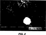
図2は内部壁にバイオフィルムを有する歯科ユニットに使用されるチューブ系の高倍率顕微鏡写真である。このバイオフィルムは約1年たったものである。
図3は本発明により洗浄した歯科用チューブ系の内部壁の全体像写真である。
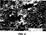
図4は本発明による処理前の別の歯科用チューブ系の内部壁の写真である。
図5は本発明による処理後の、図4の歯科用チューブ系の内部壁の全体像写真である。
図6は本発明による処理前の別の歯科用チューブ系の内部壁の写真である。
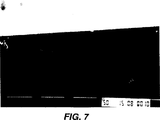
図7は本発明による処理後の、図6の歯科用チューブ系の内部壁の写真である。
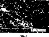
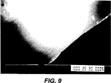
図8は本発明による処理前のさらに別の歯科用チューブ系の内部壁の写真である。
図9は本発明による処理後の、図8の壁の写真である。
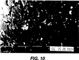
図10は処理前の歯科用チューブ系の別の部分の拡大写真である。
図11は本発明による処理後の図10のチューブ系の拡大写真である。
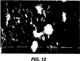
図12は処理前の更に別の歯科用チューブ系の別の内部壁の写真である。
図13は対照洗浄溶液で処理後の図12の内部壁の写真である。
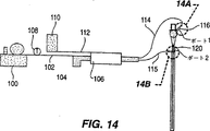
図14は内視鏡チューブ系の内部および外部表面からのバイオフィルムおよびデブリの除去に使用する装置の概略図である。
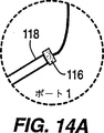
図14Aは内視鏡チューブ系の内部へ導くポートの拡大図である。
図14Bは内視鏡チューブ系の外部壁をスリーブと接続するポートの拡大図である。
図15は洗浄前の内視鏡チューブ系内部の写真である。
図16は本発明による洗浄後の内視鏡チューブ系の内部の写真である。
図17は洗浄前の内視鏡チューブ系の外部の写真である。
図18は本発明による洗浄後の内視鏡チューブ系の外部の写真である。
発明の詳細な説明
本明細書の有用な水性洗浄溶液は水及び界面活性剤を含んでおり、空気のようなガスと加圧下に混合されると、有機残渣を容易に流し落とせるようにチューブ系表面から遊離させるように作用する。本洗浄溶液は水ベースであるため、廃液処理に関する環境問題は低減されるか、または存在しない。
この水性洗浄溶液は水および界面活性剤だけを含んでもよいが、好ましくは、過酸化水素源のような酸化剤を含む。
適切な界面活性剤は非イオン性、陰イオン性または陽イオン性、またはそれらの混合物であってよい。水または水性溶液と共存可能などんな界面活性剤も使用することができ、一般には洗浄溶液の約5質量%までの濃度で使用できる。
適切な陰イオン界面活性剤には、例えばドデシル硫酸ナトリウムのようなアルキル硫酸塩およびスルホン酸塩が含まれる。除去すべき有機物質の湿潤性を増加させるため、および、水性界面活性剤含有溶液が加圧下でガスと混合された場合に作られる泡の質を改善するために非イオン性界面活性剤を添加することができる。
4級アミンのような陽イオン性界面活性剤はバイオフイルム内に存在する糖タンパク質およびバクテリア細胞壁と強く相互作用し、従って、バイオフィルム内のバクテリア性およびカビ性物質を可溶化する。陽イオン性界面活性剤はまた消毒特性を有していることが知られている。
これらの界面活性剤は水性溶液に発泡作用を与え、これは洗浄されるチューブ系に乱流を与える助けとなり、また、チューブ系表面からバイオフィルムまたはデブリを遊離させる助けとなる。特に、4級アミン界面活性剤は溶液中に、洗浄の際にガス-洗浄液混合物中に乱流を形成する更なる助けとなる小さな泡を作り出し、その効果および効率的な除去の助けとなるバイオフィルムに対するこすり落とし作用が加わる。
また、酸化剤の存在はチューブ系およびラインの内部壁および外部壁からのバイオフィルムの遊離の助けとなると考えられている。適切な酸化剤には、水性溶液中でin situに過酸化水素を発生させる水性過酸化水素溶液または過ホウ酸塩、過ヨウ素酸塩およびペルオキシカルボン酸などの過酸化化合物が含まれる。ペルオキシカーボネートその他のような固体過酸化物も更なるこすり落とし作用を与えることがある。
更に、酸化剤はチューブ系の壁からのバクテリア性物質の効果的低減の助けとなるだけでなく、バイオフィルムの再出現を低下させる殺生物特性を有している。過酸化物-界面活性剤溶液を圧縮空気と混合すると、過酸化物によって増強された厚いフロス(froth)をチューブ系内に発生させ、水と空気だけよりも効率的にバイオフィルムを除去する。酸化剤は、水性溶液の約15質量%までの量で存在するのが適切であり、好ましくは約3〜15質量%で存在する。
チューブ系の壁に対してこすり落とし作用を更に与えるために不活性粒子を本発明の水性洗浄溶液に添加することは有利であり得る。シリカ、アルミナおよびチタニア粒子のような固い不溶性粒子は界面活性剤泡とともに最も効果的なこすり落とし作用を与えるであろう。炭酸カルシウムのような不溶性の柔らかい不活性粒子、好ましくは10-300マイクロメートルのような小さな粒子サイズの不活性粒子は有利に使用することができる。これらの物質は既に歯の洗浄または歯垢の除去および歯および歯ぎんを磨くための研磨剤として通常使用されている。炭酸水素ナトリウムのような水可溶性粒子を添加することもできる。本発明によりバイオフィルムの除去は迅速に起こるため、水可溶性粒子によるある程度のこすり落とし作用が粒子の溶解前に得られる。粒子が水可溶性であるとは、粒子がリンスまたはフラッシュ工程の際に溶解することを意味し、その結果粒子はチューブ系表面から溶液として除去され、従って、洗浄後にチューブ系から洗い流さなければならない固体粒子の数を低下させる。
乱流環境において、洗浄されるチューブ系の壁に対する粒子の衝撃によってバイオフィルムのエロージョンを増加させるために上述の洗浄溶液に十分な量の不活性な不溶性粒子が添加されてもよい。しかしながら、バイオフィルムを除去するために、不活性粒子の粒子サイズは10-300ミクロンの桁でなければならず、これは例えば歯磨きに使用される粒子よりもいくぶん大きいかもしれない。粒子の形状は決定的でないが、本方法の効力を最大化すべく調製されることがある。例えば、滑らかな壁の粒子については、混合物のこすり落とし作用を増加させるために不規則形状の粒子が好まれるかもしれない。好ましい粒子は気泡によって洗浄溶液中で運ばれ得るように疎水性のものである。例えば、一般には洗浄溶液に約20質量%までの不活性粒子が添加されるのが適切である。
本発明の洗浄用混合物の使用温度は約0〜50℃で変動し得る。
ここで使用する洗浄溶液および不活性粒子は安全で非毒性である。成分の大部分は現在既に歯科業務で使用されており、従って患者に対する危険性は全く存在しない。本洗浄溶液は都市の下水道に捨てることができる。本洗浄溶液はまた安全、すなわち非毒性であり非発癌性であり、ポリビニルクロリド、ポリオレフィンおよびポリテトラフルオロエチレンチューブ系のような現在一般に入手し得るプラスチックに対して非腐食性である。
本洗浄溶液はチューブ系内部で洗浄溶液の乱流を与える加圧ガスと共に使用される。本発明は以後空気をガスとして使用するとして記載されるが、酸素、窒素、二酸化炭素、アルゴンその他のような希ガスのような他のガスで置き変えることができる。そのようなガスはシリンダー内で加圧して保存してよく、あるいは自家供給源から得ることができる。
洗浄すべきチューブ系に装填される混合物は水性溶液中でバブル(bubble)またはフロスを作りだす界面活性剤、水性溶液に対して発泡作用を与える界面活性剤、および加圧ガスを含んでいる。この混合相混合物は短時間、すなわち、約3〜10分間でバイオフィルムを遊離させ除去するために十分な体積でチューブ系に充填される。混合相洗浄溶液の体積は種々の応用について最大化させる。
上記混合物のこすり落とし作用を更に増大させるため、加圧空気はパルス化することができる。
空気または他の加圧ガスは約172kPa(25psi)より大きい圧力でデリバリーされ、歯科用チューブ系については約207kPa(30psi)から414kPa(60psi)の圧力が好ましい。しかしながら、圧力範囲は決定でなく、チューブ系直径によってより高く調整することができる。
小口径チューブ系がバイオフィルムおよび/またはデブリを緩ませた後、チューブ系からすべての固体物質を除くために水のみを圧縮空気と共に使用することができる。このフラッシュステップは一般に更に3分間からそれ以上を要する。
本発明は、実施例において、加圧洗浄水を供給する洗浄歯科チューブ系についてまず記載される。圧力は、552kPa(80psi)〜689kPa(100psi)の圧縮空気を連続的に供給可能なエアーコンプレッサーによって供給される。この圧力は歯科医によって使用される手動洗浄シリンジへ洗浄用組成物が入る前に約207kPa(30psi)〜414kPa(60psi)まで段階的に下げられる。これに対して、一般に市水系では水は約172kPa(25psi)の圧力でデリバリーされる。
図1は歯科医による使用のための改変冷却洗浄装置である。従来型のシステムはエアーコンプレッサー12、空気ライン13、圧力調整器14、ライン13の圧縮空気に水または他の水性溶液を加えるための水ライン16、歯科医がハンドヘルド器具22にデリバリーされるライン20中の空気およびライン21中の水の体積を調整できるための空気アダプター18および水アダプター19を有している。
本発明により、従来型装置は本発明の洗浄溶液を水ライン21に、これを洗浄するためにデリバリーするように改変される。
加圧空気が空気ライン13Aに向かうように三方向バルブ24が使用される。加圧空気にパルス作用を与えるためにソレノイドバルブ26がライン13Aに挿入される。
再充填可能な加圧コンテナ28は本発明の洗浄溶液を保存する。密封キャップ(示していない)により洗浄溶液が置き換えられることができ、ライン13Aは加圧空気がコンテナ28に入ることを可能にする。流出ライン30は混合チャンバー32に接続されている。
混合チャンバー32は加圧空気ライン13Aおよび洗浄溶液流出ライン30に接続されている。洗浄溶液および加圧空気は混合チャンバー32内で混合され、洗浄溶液に対する空気の比に依存して(この比は調整可能)乱流混合物またはフロスを作り出す。
さらなる加圧コンテナを装備することも可能である。図1に示すように、コンテナ34は水ライン16に接続され、例えば殺生物剤を含むことができる。コンテナ34からの出口は水ライン16に直接に接続されることも可能であり、または、洗浄溶液混合物への添加のために混合チャンバー32に接続されている。
水供給源は、本発明の洗浄溶液による洗浄に続いて歯科水ライン21を水でフラシュするため、水ライン16または混合チャンバー32に接続することができる。
このシステムにおける空気圧を制御するため、圧縮空気にパルス作用を与えるためにソレノイドバルブ26を回すため、溶液の温度を制御するため、通常の歯科ユニット操作、洗浄およびフラッシュ操作の際に3方向バルブを制御するため、チャンバー34から殺生物溶液を添加するため、その他のために、従来型のコントロールパネル(示していない)を使用することができる。歯科チューブ系を洗浄するときであると注意を警告する警報灯を備えることも可能である。所望であれば、上記のシステムは適切な収納箱に入れることができる。
このように洗浄サイクルのあいだ、トップ水ライン36はバルブV1により閉じられ、圧縮空気はバルブV2によりコンテナ28に向かわされる。ソレノイドバルブ26が作動し、コンテナ28、および必要であれば追加のコンテナ34へと通過する圧縮空気にパルス作用を作り出しす。混合チャンバー32内でフロスが形成され歯科ユニットアダプター19から歯科チューブ系水ライン21へ押し出される。
リンスまたはフラッシュサイクルの間、洗浄溶液はバルブV3によってライン30において止められ、殺生物剤またはアルカリ過酸化物溶液および水はライン13Aを通してパルス化された圧縮空気と共に混合チャンバー32へ向かうことができる。加圧された水は歯科チューブ系21を通過して洗浄溶液をフラッシュし、遊離したバイオフィルムおよびチューブ系21に残っているどんな固体粒子またはデブリをもフラッシュする。殺生物剤および/または過酸化物の添加はバイオフィルムが再形成されるまでの経過時間を増加させることがある。
フラッシュサイクルの終わりに、水道水単独またはコンテナ34に保存された殺生物剤を含む水道水を用いた歯科ユニットの通常の操作が再開される。
洗浄、フラッシュ、通常操作サイクルは製造業者または歯科医が定める一定期間の間それぞれ続く。
混合チャンバー32内の乱流は、空気:液体:粒子の比および洗浄溶液及び圧縮空気の流速を操作することによりバブルまたはフロスを与える。圧縮空気は液体小滴を作り出し、または、洗浄溶液中でいかなる固体粒子も懸濁させ、従って、溶液およびフロスまたは不活性粒子のチューブ系壁への力学的衝撃により効果的にバイオフィルムをエロージョンさせる方法を生み出す。
例として、1.8mm直径のチューブ系を通して、207kPa(30psi)〜414kPa(60psi)の空気圧を用いて押し出される空気は9700から15,000の間のレーノルズ数を有し、管型幾何学構造においては乱流と考えられる。洗浄溶液に不活性粒子または液滴を加えることは溶液の洗浄効果をさらに増加させる。バイオフィルムが5〜10μmの厚さを有する場合は、適用する空気圧と摩擦力との関係は既知の一次元エネルギー式によって評価できる。
直径1.8mm、長さ2.44m(8フィート)の歯科チューブ系において計算値と測定された速度は互いによく一致した。
更に、ある種の歯科チューブ系が連続的にカールしているということは、それがチューブ系壁に対して空気、固体粒子および溶液のランダムな衝撃を与え、バイオフィルムを迅速かつ完全に遊離または侵食させるので、本洗浄法にとって優れた幾何学構造である。
本発明は、洗浄歯科チューブ系についての以下の実施例1〜6において説明されるが、本発明はそこで記載される細部に限定することを意図していない。実施例中、%は特に記載のない限り質量%である。
実施例1
内部表面に1年経過したバイオフィルムを有する歯科チューブ系の一部を図2に示した。バイオフィルムはチューブ系の内部表面を完全に被覆しており約200,000コロニー/cmのバクテリアからなっている。
このチューブ系の0.9m(3フィート)の部分を本発明に従って、大きさ50-100μmの炭酸カルシウム不活性粒子5質量%、および約2%の陰イオン界面活性剤ドデシル硫酸ナトリウム、約1%の非イオン性界面活性剤を含む界面活性剤を含有する3%過酸化水素水溶液の洗浄溶液を用いて処理した。この洗浄溶液を図1の混合チャンバー28に添加し、この混合チャンバーに207kPa(30psi)〜414kPa(60psi)に制御した1HPエアーコンプレッサーから空気を加え、空気は連続パルス化した。成分の混合およびチューブ系内で作られる乱流を最適化するべく空気量とパルス速度を制御した。混合物を歯科チューブ系に通し乱流がチューブ系を洗浄できるようにした。
次にチューブ系を蒸留水でフラッシュした。洗浄したチューブ系の内部表面を図3に示した。バイオフィルムが完全に除去されていることが明らかである。
洗浄したチューブ系の2.5cmの長さ部分の内部表面をこすり、チューブ系のその部分の水を集めることによりバクテリアについて以下のようにチューブ系をテストした。チューブ系を半分に、約1.25cmの長さに切り、3つの小片を4℃で保存した。各小片の管腔をスカルペルの刃先で15回こすり、一切のバクテリアを剥離し、存在する一切のバクテリアを懸濁するためスカルペルおよびチューブ系を水中で1分間激しく揺すった。得られた懸濁液を蒸留水で10倍に希釈し、希釈ペプトン寒天プレート上に広げた。チューブ系内の水も希釈してプレーティングした。このプレートを25℃にて2週間インキュベーションし、グラム染色カリトース(calitose)反応、オキシダーゼとグルコース発酵テストを含む通常のやり方に従ってバクテリアコロニーを計測および同定した。バクテリアの総数および生存バクテリアの総数をHobbeら、Applied & Environmental Microbioloy, 1977年5月号、1225−1228頁、およびKogureら、Can. J. of Microbiology, vol.25, 415-420(1979)の方法に従って計測した。
洗浄したチューブ系はわずかに280コロニー/(チューブ系cm)しか有しなかったが、未処理のチューブ系は約200,000コロニー/(チューブ系cm)を有していた。このように、1000倍のバクテリア数減少が得られた。図4の大きい白い粒子は水の硬度のせいで長期間の間に蓄積した沈着と考えられる。
実施例2
10〜100μmの大きさの粒子を有する50gの炭酸カルシウム粒子を、3質量%の過酸化水素水溶液、2質量%の界面活性剤、ドデシル硫酸ナトリウムおよび、1%の非イオン界面活性剤を含む溶液450ml中に混合することにより洗浄溶液を作製した。
上記混合物を図4に示すようなバイオフィルムをその表面上に有する0.9m(3フィート)長、直径1.8mmの使用済み歯科チューブ系内に207kPa(30psi)〜414kPa(60psi)の間に設定したコンプレッサーによって供給される空気と共に上記混合物を導入した。洗浄用組成物を約3分間チューブ系を通してフラッシュした。
次にチューブ系を200mlの蒸留水でフラッシュした。
チューブ系内のバクテリアコロニー数はチューブ系の直線cmあたりの初期値7.15x10⁵から洗浄後には0に低下した。チューブ内を流れる水のCFU/mlは初期値3.19x106から洗浄後に0に低下した。
図5のSEM写真は処理後のチューブ系の内部壁の全体像である。図5はチューブ系の管腔内のバイオフィルムの完全な除去を示している。チューブ系の裸の表面にはいかなるデブリまたはバイオフィルムも存在しなかった。
実施例3
576mlの3質量%過酸化水素水溶液を2質量%のドデシル硫酸ナトリウム界面活性剤と混和した。この洗浄剤を207kPa(30psi)〜414kPa(60psi)の間に設定したコンプレッサーによって供給される空気と共に使用済み歯科チューブ系へ導入した。3分間の処理後、このチューブ系を200mlの水でフラッシュした。
チューブ系1cmあたりの培養後のバクテリア数は初期値1x10⁵から0まで減少した。水のCFU/mlは初期値3.01x106から0に減少した。
図6は処理前のチューブ系の内部壁の写真である。図7は処理後のチューブ系の内部壁の写真である。
このように、過酸化水素、界面活性剤と所定の圧力の空気の存在下で、固体粒子の非存在下であっても完全な洗浄が達成された。
実施例4
実施例2の手順を行なったが、但し、過酸化水素溶液を蒸留水に置き換えた。
CFU/cmは初期値4x105から0まで低下した。従って、水、界面活性剤、研磨粒子および所定の圧力の空気はチューブ系からバイオフィルムを除くのに十分であった。
図8は処理前のチューブ系の内部表面の写真である。
図9は、この実施例による処理後のチューブ系の内部表面の写真である。
実施例5
193mlの3質量%の過酸化水素、3質量%のドデシル硫酸ナトリウム界面活性剤および50-100gの水可溶性炭酸水素ナトリウム粒子から洗浄溶液を作製した。この溶液を蒸留水で600gにした。
この洗浄溶液を207kPa(30psi)〜414kPa(60psi)の間に設定したコンプレッサーからの空気と共に使用済み歯科チューブ系内へ3分間導入した。このチューブ系を次に蒸留水でフラッシュした。
CFU/cmは初期値5.5x104から0まで減少し、CFU/mlは初期値3x106から0まで低下した。図10のSEM写真は処理前のバイオフィルムの存在を示し、図11から分かるように、処理後のチューブ系管腔内からのバイオフィルムの完全な除去を示している。
実施例6
5%ドデシル硫酸ナトリウム界面活性剤およびペルオキシカルボネートおよび1%のポリリン酸塩の混合物と水とを総量600mlに混合した。この混合物を207kPa(30psi)〜414kPa(60psi)の間に設定したコンプレッサーから供給される圧力下で空気と共に使用済み歯科チューブ系内へ3分間導入した。このチューブ系を次に200mlの水でフラッシュした。
CFU/cmは初期値1.25x105から0まで低下し、CFU/mlは初期値3x106から0まで低下した。
対照
対照として、水だけを207kPa(30psi)〜414kPa(60psi)の間に設定したコンプレッサーからの空気と共に混合し、使用済み歯科チューブ系に3分間通した。
CFU/cmは初期値7.5x104から3.5x104へ低下した。しかしながら、水のCFU/mlは2.5x106から処理後に2.38x106に低下しただけであった。
図12のSEM写真は対照処理前のバイオフィルムの存在を示し、図13は処理後のバイオフィルムのわずか約30%の低下しか示していない。
このように、空気と水の物理的力はチューブ系からバイオフィルムを除去するのに十分でない。
歯科用および医療用チューブ系を実質的なバイオフィルム蓄積無しに十分に維持するために、上記処理は少なくとも約100時間ごとに繰り返されなければならない。
バイフォフィルムは時間が経つとバクテリアコロニーが増えるだけでなく、チューブ系の表面により接着性になる。従って、処理が頻繁に繰り返される場合、例えば、4〜5日ごとの場合、バイオフィルムは本発明の組成物及び方法で比較的除去が容易なままに止まる。
本洗浄溶液および方法はまたチューブ系からバイオフィルムに加えて、有機物フィルム、粘液性または固体デブリ、例えば組織、遊離細胞(loose cell)、食品粒子その他のような、チューブ系壁に接着する他の汚染物を除去するためにも使用することができる。
このような洗浄の主たる適用物は内視鏡チューブ系であり、これは本発明により内部および外部壁の両方について洗浄できる。図14は内視鏡チューブの内部壁および外部壁の両方を洗浄するために使用され得る洗浄装置の概略図である。
エアーコンプレッサー100はライン102内の空気を圧縮空気パルスコントロールノズル104を通して混合チャンバー106に送る。圧力調節器108は空気流を制御する。洗浄溶液保存用チャンバー110はライン112を通して洗浄溶液を混合チャンバー106へ送る。得られた加圧空気と洗浄溶液の乱流混合物は、内視鏡チューブ120のポート118への気密適合性を与えるアダプター116(図14Aを見よ)へライン114によって送られる。図14Aはアダプター116と内視鏡ポート118の拡大図である。
図14Bは、洗浄溶液を運ぶライン115を内視鏡チューブの外部表面に適合させるためアダプター126によって気密スリーブ124を締めつける外部ポート122の拡大図である。スリーブ124はセルロース材料、ポリオレフィンおよびポリエステルのような、どんな柔軟なプラスチックで製造することもできる。
内視鏡チューブの洗浄を行なうため、図14、図14Aおよび図14Bの装置を使用して、以下の実施例を行なった。
実施例7
約1.8m(6フィート)の長さと約0.110cmの内径を有する柔軟なチューブ系を部分的に炭水化物(デンプン)、タンパク質および糖を含む食品デブリ混合物で満たし、一晩乾燥させた。この残渣は内視鏡処置後に残るデブリをシミュレートすべく意図されたものである。低倍率図である図15においてこのデブリが明瞭に見える。
第1段階において、デブリ残渣を柔らかくするため5〜10分間水で内部チャンネルを満たした。
0.05%のオクチルデシルジメチルアンモニウムクロリド、0.025%のジオクチルジメチルアンモニウムクロリド、および0.025%のジデシルジメチルアンモニウムクロリドおよび、4%の過酸化水素と混合された約1%の非イオン性および陰イオン性界面活性剤の混合物を洗浄溶液として使用した。この溶液500mlを552kPa(80psi)までの空気と混合し、5分間にわたってチャンネルに通した。
次に1リットルの水で通路をフラッシュした。
次にチャンネルを加圧空気と一緒に200mlの3〜7%過酸化水素溶液を用いて消毒した。次にチャンネルを5分間風乾した。チューブ系の内部壁は図16に示されるように、全てのデブリが洗い落とされていた。
実施例8
実施例7の方法を繰り返したが、洗浄溶液は陰イオン性と非イオン性界面活性剤の両方を3%過酸化水素溶液中に2%濃度まで含むものとした。全てのデブリは除去された。
実施例9
実施例7の方法を繰り返したが、洗浄溶液は最初に界面活性剤を蒸留水に溶かすことによって作製した。全てのデブリは除去された。
実施レ10
実施例7の方法を繰り返したが、粒子サイズ50〜200μmの5%の炭酸カルシウム粒子を洗浄溶液に分散させた。全てのデブリは除去された。
実施例11
実施例8の方法を繰り返したが、粒子サイズ50〜200μmの5%の炭酸カルシウム粒子を洗浄溶液に分散させた。全てのデブリは除去された。
炭酸水素ナトリウムなどの可溶性粒子を水不溶性炭酸カルシウム粒子と置換することができる。
実施例12
約2.1m(7フィート)、直径1.1cmの内視鏡チューブの外部表面を実施例7のデブリ混合物に浸漬し一晩乾燥させた。図17の写真はチューブ系の外部表面に付着したデブリを明瞭に示している。
チューブのステムを直径1.4cmの柔軟なセルロースポリマースリーブ内に挿入した。スリーブとチューブを密閉アダプターによって一緒に接続した。実施例7の洗浄溶液(500ml)を689kPa(100psi)までの圧力の空気と混合し、スリーブ中へ5分間通した。水フラッシュサイクル、消毒サイクル、および乾燥サイクルを実施例7のように行った。全てのデブリは図18にみられるようにチューブ系の外部表面から除去された。
本洗浄溶液は、補綴インプラントおよび成人および新生児ケアの双方のための呼吸器のような洗浄すべき表面へ加圧下で撒布することもできる。
本発明は具体的な実施態様によって記載されてきたが、本発明はそのように限定されることを意図していない。本発明は添付の請求の範囲によってのみ限定されるべきである。The present invention provides a mixed phase wash solution and method for removing potentially pathogenic bacteria and other microorganisms, debris, tissue, food debris, etc. from lines and tubing, and The present invention relates to an apparatus for sending and washing the mixed phase washing solution under pressure to a line and a tube system.
BACKGROUND OF THE INVENTION A small-bore tube system that delivers purified or unpurified normal running water to equipment such as a dental unit, as is well known, causes bacterial and mold growth on its internal surface. Bacteria present in the water strongly adhere to the tube system surface and multiply laterally to form what is known as a biofilm. Biofilm is understood as a slimy film when touched, and analysis has shown that it is bacterial growth.
In the prior art, several researchers have identified various bacteria in these biofilms, including Flavobacteriium, Moraxella, Achromobacter, Pseudomonas, It contains several potentially pathogenic bacteria such as Alcaligenes, Micrococcus and Legionella. All of these bacteria can cause infections in humans, and Legionella is of particular interest because it is highly resistant to antibiotics and its infection is fatal. Also, organisms such as Legionella can be inhaled from contaminated water sprays during dental or other medical treatments.
Dental unit tube systems that carry rinsing water to the patient's mouth have been determined to contain more than 1 million (1 × 10 6 ) colony forming units (1 × 10 6 CFU / ml) per ml of water after one week of use. Accordingly, these water lines and tube systems must be periodically cleaned to ensure removal of biofilm on the tube walls to prevent infection. The possibility of infection in patients with immune disorders is also a major concern. If the patient has any open wounds in the mouth, the risk of infection is naturally very high.
However, biofilms are very difficult to remove from the tube system. Biofilms adhere strongly to smooth tube surfaces, whether the tubing is made of natural materials or synthetic materials such as rubber-based materials, polyethylene, polytetrafluoroethylene, etc. It is. Treatment with disinfectants and biocides will kill the bacteria and thereby remove the biofilm. However, these drugs do not diffuse easily into biofilms that adhere tightly to the tube wall, so removal is usually only partial and the biofilm reproduces very quickly. A reduction in the level of bacteria present in the water delivery system to below 200 CFU / ml has been proposed by the American Dental Association.
Other applications that use small-bore tubing that should be cleaned regularly are used in endoscope tubing, catheter tubing, sterile filling ports, and sterile manufacturing, food processing, etc. Tube system is included. In addition to biofilms, these tube system types may contain food pieces, tissue pieces, mucus, blood, etc., which are hereinafter referred to as “debris”. Such tube systems must also be thoroughly cleaned between each use and each use to prevent infection from one patient to another.
Gastrointestinal endoscope unit cleaning guidelines promulgated by the American Gastrointestinal Endoscopy Society include a multi-step method for tube cleaning between patients to prevent infection. Initially, mechanical cleaning with a brush is performed immediately after use with a cleaning solution. The tube system is then rinsed with water and then sterilized using a disinfectant such as a glutaraldehyde solution. The tube system is then rinsed again with water and ventilated to dry.
Another application of the invention is a respiratory organ for both newborns and adults, which must be cleaned about every 8 hours. Such cleaning is expensive but necessary.
Therefore, improved cleaning compositions that remove biofilm and debris from the inner and outer surfaces of the tube system in a cost-effective manner and prevent or delay the reappearance of the biofilm, and their cleaning solutions Devices that deliver to line and tube systems would be highly desirable.
SUMMARY OF THE INVENTION The present invention uses a combination of pressurized gas and a suitable aqueous cleaning solution to create a turbulent environment on or within a tube having biofilm or debris on its internal or external surface. This completely removes biofilm and debris. A suitable aqueous cleaning solution includes water and a surfactant. Oxidizing agents and biocides can also be added. Inert particles that can be rubbed off can also be advantageously added to the aqueous cleaning solution. This aqueous cleaning composition is sent to a tube system that is cleaned by compressed gas, thereby creating a mixed phase system that provides turbulent flow along the tube wall and helps release biofilm and debris from the tube surface, Helps flush the material released from the tube.
The present invention also includes an apparatus for delivering the mixed phase wash solution to the interior of the small bore tube system and line and mixing with the gas under pressure. The compressed gas-aqueous cleaning solution combination creates turbulence inside the tube system, which helps release the biofilm from the inner surface of the tube system so that the biofilm is easier to flush and rinse with water. Can be removed.
The present invention also provides the aforementioned cleaning solution to a small diameter tube system and the outer surface of the line by enclosing the tube system in a pressure resistant cylinder having an adapter that provides an airtight seal between the cleaning solution-pressurized gas mixture and the tube system. A device for delivery to the device is also included. This device has a mixing chamber for mixing aqueous solutions, optionally solid particles, and gas under pressure and delivering them to the line and tube system to be cleaned.
[Brief description of the drawings]
FIG. 1 is a schematic view of the aqueous cleaning composition delivery system of the present invention.
FIG. 2 is a high-magnification micrograph of a tube system used in a dental unit having a biofilm on the inner wall. This biofilm is about one year old.
FIG. 3 is a picture of the entire inner wall of a dental tube system cleaned according to the present invention.
FIG. 4 is a photograph of the inner wall of another dental tube system prior to treatment according to the present invention.
FIG. 5 is a picture of the entire interior wall of the dental tube system of FIG. 4 after processing according to the present invention.
FIG. 6 is a photograph of the inner wall of another dental tube system before processing according to the present invention.
FIG. 7 is a photograph of the inner wall of the dental tube system of FIG. 6 after processing according to the present invention.
FIG. 8 is a photograph of the inner wall of yet another dental tube system before processing according to the present invention.
FIG. 9 is a photograph of the wall of FIG. 8 after processing according to the present invention.
FIG. 10 is an enlarged photograph of another part of the dental tube system before processing.
FIG. 11 is an enlarged photograph of the tube system of FIG. 10 after treatment according to the present invention.
FIG. 12 is a photograph of another internal wall of yet another dental tube system before processing.
FIG. 13 is a photograph of the inner wall of FIG. 12 after treatment with the control wash solution.
FIG. 14 is a schematic diagram of an apparatus used to remove biofilm and debris from the internal and external surfaces of an endoscopic tube system.
FIG. 14A is an enlarged view of a port leading to the inside of the endoscope tube system.
FIG. 14B is an enlarged view of the port connecting the outer wall of the endoscope tube system to the sleeve.
FIG. 15 is a photograph of the inside of the endoscope tube system before washing.
FIG. 16 is a photograph of the inside of the endoscope tube system after washing according to the present invention.
FIG. 17 is a photograph of the exterior of the endoscope tube system before washing.
FIG. 18 is a photograph of the exterior of the endoscope tube system after washing according to the present invention.
DETAILED DESCRIPTION OF THE INVENTION Useful aqueous cleaning solutions herein contain water and a surfactant and are tube systems so that organic residues can be easily washed away when mixed with a gas such as air under pressure. It acts to release from the surface. Since the cleaning solution is water based, environmental problems associated with waste liquid treatment are reduced or absent.
This aqueous cleaning solution may contain only water and a surfactant, but preferably contains an oxidizing agent such as a source of hydrogen peroxide.
Suitable surfactants can be nonionic, anionic or cationic, or mixtures thereof. Any surfactant that is compatible with water or an aqueous solution can be used, generally at a concentration of up to about 5% by weight of the cleaning solution.
Suitable anionic surfactants include alkyl sulfates and sulfonates such as sodium dodecyl sulfate. Add non-ionic surfactants to increase the wettability of organic substances to be removed and to improve the quality of foam created when aqueous surfactant-containing solutions are mixed with gas under pressure can do.
Cationic surfactants such as quaternary amines interact strongly with the glycoproteins and bacterial cell walls present in the biofilm, and thus solubilize bacterial and fungal substances within the biofilm. Cationic surfactants are also known to have disinfecting properties.
These surfactants impart a foaming action to the aqueous solution, which helps to provide turbulence to the tube system being cleaned and also helps to release biofilm or debris from the tube system surface. In particular, quaternary amine surfactants create small bubbles in solution, which aid in the formation of turbulent flow in the gas-cleaning liquid mixture during cleaning, and their bioactivity helps in efficient removal. Adds a scraping action to the film.
It is also believed that the presence of an oxidant helps release the biofilm from the inner and outer walls of the tube system and line. Suitable oxidizing agents include aqueous hydrogen peroxide solutions that generate hydrogen peroxide in situ in aqueous solutions or peroxide compounds such as perborate, periodate and peroxycarboxylic acid. Solid peroxides such as peroxycarbonates can also provide additional scrubbing action.
In addition, oxidants not only help effectively reduce bacterial material from the walls of the tube system, but also have biocidal properties that reduce biofilm reappearance. When the peroxide-surfactant solution is mixed with compressed air, a thick froth enhanced by peroxide is generated in the tube system, removing the biofilm more efficiently than water and air alone. The oxidant is suitably present in an amount up to about 15% by weight of the aqueous solution, preferably about 3-15% by weight.
It may be advantageous to add inert particles to the aqueous cleaning solution of the present invention to further provide a scrubbing action on the tube system walls. Hard insoluble particles such as silica, alumina and titania particles will give the most effective scrubbing action with the surfactant foam. Insoluble soft inert particles such as calcium carbonate, preferably inert particles with a small particle size such as 10-300 micrometers, can be used advantageously. These materials are already commonly used as abrasives for already cleaning teeth or removing plaque and brushing teeth and gums. Water soluble particles such as sodium bicarbonate can also be added. Since removal of the biofilm occurs rapidly according to the present invention, a certain amount of scraping action by the water-soluble particles is obtained before dissolution of the particles. Particles that are water soluble mean that the particles dissolve during the rinsing or flushing process, so that the particles are removed as a solution from the tube system surface and therefore must be washed away from the tube system after washing. Reduce the number of particles.
In a turbulent environment, a sufficient amount of inert insoluble particles may be added to the cleaning solution described above to increase biofilm erosion by impact of the particles against the wall of the tube system being cleaned. However, in order to remove the biofilm, the particle size of the inert particles must be on the order of 10-300 microns, which may be somewhat larger than, for example, particles used for toothpaste. The shape of the particles is not critical, but may be prepared to maximize the efficacy of the method. For example, for smooth wall particles, irregularly shaped particles may be preferred to increase the scraping action of the mixture. Preferred particles are hydrophobic so that they can be carried in the cleaning solution by bubbles. For example, it is generally appropriate to add up to about 20% by weight of inert particles to the cleaning solution.
The use temperature of the cleaning mixture of the present invention can vary from about 0-50 ° C.
The cleaning solution and inert particles used here are safe and non-toxic. Most of the ingredients are already used in dental practice now, so there is no risk to the patient. This cleaning solution can be discarded into the city sewer. The cleaning solution is also safe, ie, non-toxic and non-carcinogenic, and non-corrosive to currently commonly available plastics such as polyvinyl chloride, polyolefins and polytetrafluoroethylene tube systems.
The cleaning solution is used with a pressurized gas that provides a turbulent flow of the cleaning solution within the tube system. The present invention will be described hereinafter using air as a gas, but can be replaced with other gases such as noble gases such as oxygen, nitrogen, carbon dioxide, argon and the like. Such a gas may be stored under pressure in a cylinder or may be obtained from an in-house source.
The mixture charged to the tube system to be cleaned contains a surfactant that creates a bubble or floss in the aqueous solution, a surfactant that provides a foaming action to the aqueous solution, and a pressurized gas. This mixed phase mixture is filled into the tube system in a sufficient volume to release and remove the biofilm in a short period of time, ie, about 3-10 minutes. The volume of the mixed phase wash solution is maximized for various applications.
To further increase the scraping action of the mixture, the pressurized air can be pulsed.
Air or other pressurized gas is delivered at a pressure greater than about 172 kPa (25 psi), and pressures of about 207 kPa (30 psi) to 414 kPa (60 psi) are preferred for dental tubing. However, the pressure range is not determined and can be adjusted higher by the tube system diameter.
After the small bore tube system has loosened the biofilm and / or debris, only water can be used with the compressed air to remove all solid material from the tube system. This flush step generally requires an additional 3 minutes or more.
The present invention is first described in the Examples for a cleaning dental tube system that supplies pressurized cleaning water. The pressure is supplied by an air compressor capable of continuously supplying compressed air of 552 kPa (80 psi) to 689 kPa (100 psi). This pressure is stepped down from about 207 kPa (30 psi) to 414 kPa (60 psi) before the cleaning composition enters the manual cleaning syringe used by the dentist. In contrast, in city water systems, water is generally delivered at a pressure of about 172 kPa (25 psi).
FIG. 1 is a modified cold cleaning device for use by a dentist. Conventional systems include an
In accordance with the present invention, the conventional device is modified to deliver the cleaning solution of the present invention to the
A three-
A refillable
The mixing
It is also possible to equip additional pressurized containers. As shown in FIG. 1, a
A water source can be connected to the
In order to control the air pressure in this system, to turn the
Thus, during the wash cycle, the top water line 36 is closed by the valve V1, and the compressed air is directed to the
During the rinse or flush cycle, the wash solution is stopped in
At the end of the flush cycle, normal operation of the dental unit with tap water alone or with tap water containing a biocide stored in
The cleaning, flushing, and normal operating cycles each last for a period of time determined by the manufacturer or dentist.
Turbulence in the mixing
As an example, air extruded through a 1.8 mm diameter tube system using air pressures of 207 kPa (30 psi) to 414 kPa (60 psi) has a Reynolds number between 9700 and 15,000, and is turbulent in tubular geometry it is conceivable that. Adding inert particles or droplets to the cleaning solution further increases the cleaning effect of the solution. When the biofilm has a thickness of 5 to 10 μm, the relationship between the applied air pressure and the frictional force can be evaluated by a known one-dimensional energy equation.
The calculated and measured velocities agreed well with each other in a dental tube system with a diameter of 1.8 mm and a length of 2.44 m (8 feet).
In addition, certain dental tube systems are continuously curled, which gives a random impact of air, solid particles and solutions to the tube system walls, releasing the biofilm quickly and completely. Since it erodes, it is an excellent geometric structure for this cleaning method.
The present invention is illustrated in the following Examples 1-6 for a cleaning dental tube system, but the present invention is not intended to be limited to the details described therein. In Examples,% is% by mass unless otherwise specified.
Example 1
A portion of a dental tube system with a biofilm a year old on the inner surface is shown in FIG. The biofilm completely covers the inner surface of the tube system and consists of about 200,000 colonies / cm of bacteria.
A 0.9 m (3 ft) portion of this tube system is in accordance with the present invention 5% by weight of calcium carbonate inert particles 50-100 μm in size and about 2% anionic surfactant sodium dodecyl sulfate, about 1% This was treated with a 3% aqueous hydrogen peroxide cleaning solution containing a surfactant including a non-ionic surfactant. This cleaning solution was added to the mixing
The tube system was then flushed with distilled water. The internal surface of the cleaned tube system is shown in FIG. It is clear that the biofilm has been completely removed.
The tube system was tested for bacteria as follows by rubbing the inner surface of a 2.5 cm long section of the washed tube system and collecting the water in that part of the tube system. The tube system was cut in half and approximately 1.25 cm long and the three pieces were stored at 4 ° C. The lumen of each piece was rubbed 15 times with a scalpel blade to detach any bacteria, and the scalpel and tube system were shaken vigorously in water for 1 minute to suspend any bacteria present. The resulting suspension was diluted 10-fold with distilled water and spread on diluted peptone agar plates. The water in the tube system was also diluted and plated. The plates were incubated for 2 weeks at 25 ° C., and bacterial colonies were counted and identified according to conventional procedures including Gram-stained calitose reaction, oxidase and glucose fermentation tests. The total number of bacteria and the total number of living bacteria are described in Hobbe et al., Applied & Environmental Microbioloy, May 1977, pages 1225-1228, and Kogure et al., Can. J. of Microbiology, vol. 25, 415-420 (1979). It was measured according to the method.
The washed tube system had only 280 colonies / (tube system cm), while the untreated tube system had about 200,000 colonies / (tube system cm). Thus, a 1000-fold reduction in the number of bacteria was obtained. The large white particles in FIG. 4 are considered to have accumulated over a long period of time due to the hardness of water.
Example 2
A solution containing 50 g calcium carbonate particles having a particle size of 10 to 100 μm containing 3% by mass aqueous hydrogen peroxide, 2% by mass surfactant, sodium dodecyl sulfate and 1% nonionic surfactant A wash solution was made by mixing in 450 ml.
The mixture was set between 207 kPa (30 psi) and 414 kPa (60 psi) in a 0.9 m (3 ft) long, 1.8 mm diameter spent dental tube system with a biofilm on its surface as shown in FIG. The above mixture was introduced with the air supplied by the compressor. The cleaning composition was flushed through the tube system for about 3 minutes.
The tube system was then flushed with 200 ml distilled water.
The number of bacterial colonies in the tube system decreased from the initial value of 7.15 × 10 5 per linear centimeter of the tube system to 0 after washing. The CFU / ml of water flowing in the tube decreased from the initial value of 3.19 × 10 6 to 0 after washing.
The SEM photograph in FIG. 5 is an overall image of the inner wall of the tube system after processing. FIG. 5 shows the complete removal of the biofilm within the lumen of the tube system. There was no debris or biofilm present on the bare surface of the tube system.
Example 3
576 ml of a 3% by weight aqueous hydrogen peroxide solution was mixed with 2% by weight sodium dodecyl sulfate surfactant. This detergent was introduced into the used dental tube system with air supplied by a compressor set between 207 kPa (30 psi) and 414 kPa (60 psi). After 3 minutes of treatment, the tube system was flushed with 200 ml of water.
The number of bacteria after culturing per 1 cm of the tube system decreased from the initial value of 1 × 10 5 to 0. The CFU / ml of water decreased from the initial value of 3.01 × 10 6 to 0.
FIG. 6 is a photograph of the inner wall of the tube system before processing. FIG. 7 is a photograph of the inner wall of the tube system after processing.
Thus, complete cleaning was achieved in the presence of hydrogen peroxide, surfactant and air at a given pressure, even in the absence of solid particles.
Example 4
The procedure of Example 2 was followed except that the hydrogen peroxide solution was replaced with distilled water.
CFU / cm decreased from the initial value of 4 × 10 5 to 0. Thus, water, surfactant, abrasive particles and air at a given pressure were sufficient to remove the biofilm from the tube system.
FIG. 8 is a photograph of the inner surface of the tube system before treatment.
FIG. 9 is a photograph of the inner surface of the tube system after treatment according to this example.
Example 5
A cleaning solution was made from 193 ml of 3 wt% hydrogen peroxide, 3 wt% sodium dodecyl sulfate surfactant and 50-100 g of water soluble sodium bicarbonate particles. This solution was made up to 600 g with distilled water.
This cleaning solution was introduced into the used dental tubing with air from a compressor set between 207 kPa (30 psi) and 414 kPa (60 psi) for 3 minutes. The tube system was then flushed with distilled water.
CFU / cm decreased from an initial value of 5.5 × 10 4 to 0, and CFU / ml decreased from an initial value of 3 × 10 6 to 0. The SEM picture of FIG. 10 shows the presence of the biofilm before processing, and as can be seen from FIG. 11, shows complete removal of the biofilm from within the tubular lumen after processing.
Example 6
A mixture of 5% sodium dodecyl sulfate surfactant and peroxycarbonate and 1% polyphosphate and water was mixed to a total volume of 600 ml. This mixture was introduced into the used dental tubing for 3 minutes with air under pressure supplied from a compressor set between 207 kPa (30 psi) and 414 kPa (60 psi). The tube system was then flushed with 200 ml water.
CFU / cm decreased from an initial value of 1.25 × 10 5 to 0, and CFU / ml decreased from an initial value of 3 × 10 6 to 0.
Control As a control, only water was mixed with air from the compressor set between 207 kPa (30 psi) and 414 kPa (60 psi) and passed through the used dental tubing for 3 minutes.
CFU / cm decreased from the initial value of 7.5 × 10 4 to 3.5 × 10 4 . However, the CFU / ml of water only dropped from 2.5 × 10 6 to 2.38 × 10 6 after treatment.
The SEM picture in FIG. 12 shows the presence of the biofilm before the control treatment, and FIG. 13 shows only a reduction of about 30% of the biofilm after the treatment.
Thus, the physical forces of air and water are not sufficient to remove the biofilm from the tube system.
In order to maintain the dental and medical tubing sufficiently without substantial biofilm accumulation, the process must be repeated at least about every 100 hours.
Bifofilm not only increases bacterial colonies over time, but also becomes more adherent to the surface of the tube system. Thus, if the treatment is repeated frequently, for example every 4-5 days, the biofilm remains relatively easy to remove with the compositions and methods of the present invention.
The cleaning solution and method can also be used in addition to biofilms from tube systems, as well as other films that adhere to tube system walls, such as organic films, mucous or solid debris such as tissues, loose cells, food particles, etc. It can also be used to remove contaminants.
The main application of such cleaning is the endoscope tube system, which can clean both the inner and outer walls according to the invention. FIG. 14 is a schematic view of a cleaning device that can be used to clean both the inner and outer walls of an endoscope tube.
The
FIG. 14B is an enlarged view of the
In order to clean the endoscope tube, the following examples were carried out using the apparatus of FIGS. 14, 14A and 14B.
Example 7
A flexible tube system having a length of about 1.8 m (6 feet) and an inner diameter of about 0.110 cm was partially filled with a food debris mixture containing carbohydrate (starch), protein and sugar and allowed to dry overnight. This residue is intended to simulate debris remaining after the endoscopic procedure. This debris is clearly visible in FIG. 15, which is a low magnification view.
In the first stage, the inner channel was filled with water for 5-10 minutes to soften the debris residue.
About 1% nonionic and anionic interface mixed with 0.05% octyldecyldimethylammonium chloride, 0.025% dioctyldimethylammonium chloride, and 0.025% didecyldimethylammonium chloride and 4% hydrogen peroxide A mixture of activators was used as a wash solution. 500 ml of this solution was mixed with air up to 552 kPa (80 psi) and passed through the channel for 5 minutes.
The passage was then flushed with 1 liter of water.
The channel was then disinfected with 200 ml of 3-7% hydrogen peroxide solution with pressurized air. The channel was then air dried for 5 minutes. As shown in FIG. 16, the inner wall of the tube system had all debris washed away.
Example 8
The method of Example 7 was repeated, but the cleaning solution contained both anionic and nonionic surfactants in a 3% hydrogen peroxide solution to a concentration of 2%. All debris was removed.
Example 9
The method of Example 7 was repeated, but the cleaning solution was made by first dissolving the surfactant in distilled water. All debris was removed.
The method of Example 7 was repeated, but 5% calcium carbonate particles having a particle size of 50-200 μm were dispersed in the cleaning solution. All debris was removed.
Example 11
The method of Example 8 was repeated, but 5% calcium carbonate particles having a particle size of 50-200 μm were dispersed in the cleaning solution. All debris was removed.
Soluble particles such as sodium bicarbonate can be replaced with water-insoluble calcium carbonate particles.
Example 12
The outer surface of an endoscope tube approximately 2.1 m (7 feet) and 1.1 cm in diameter was immersed in the debris mixture of Example 7 and allowed to dry overnight. The photograph in FIG. 17 clearly shows debris adhering to the outer surface of the tube system.
The stem of the tube was inserted into a flexible cellulose polymer sleeve with a diameter of 1.4 cm. The sleeve and tube were connected together by a sealing adapter. The cleaning solution of Example 7 (500 ml) was mixed with air at a pressure up to 689 kPa (100 psi) and passed through the sleeve for 5 minutes. A water flush cycle, disinfection cycle, and drying cycle were performed as in Example 7. All debris was removed from the outer surface of the tubing as seen in FIG.
The cleaning solution can also be applied under pressure to surfaces to be cleaned such as prosthetic implants and respiratory for both adult and neonatal care.
Although the present invention has been described in terms of specific embodiments, the present invention is not intended to be so limited. The present invention should be limited only by the appended claims.
Claims (14)
(a)水および1以上の界面活性剤から洗浄溶液を作成すること、
(b)前記洗浄溶液を加圧されたガスと混合して乱流混合相混合物を形成させること、
(c)前記チューブ系の内部表面に前記乱流混合相混合物を通過させるためのアダプターを提供すること、および、
(d)前記乱流混合相混合物を前記チューブ系の内部表面へ通すこと
を含む、前記方法。A method for cleaning an inner surface of an endoscope tube system,
(A) creating a cleaning solution from water and one or more surfactants;
(B) mixing the cleaning solution with a pressurized gas to form a turbulent mixed phase mixture;
(C) providing a adapter over for passing the turbulent mixing phase mixture to the inner surface of the tubing, and,
(D) passing the turbulent mixed phase mixture through an inner surface of the tube system.
(a)内視鏡チューブ系をアダプターでスリーブ中に封じ込めて前記チューブ系と前記スリーブ間に耐圧シールを提供すること、
(b)水および1以上の界面活性剤を含む洗浄溶液を作成すること、
(c)前記洗浄溶液を加圧されたガスと混合して乱流混合相混合物を形成させること、および
(d)前記乱流混合相混合物を前記チューブ系の外部表面と前記スリーブの間を通過させること、
を含む前記方法。A method for cleaning an external surface of an endoscope tube system,
(A) encapsulating the endoscope tube system in a sleeve with an adapter to provide a pressure-resistant seal between the tube system and the sleeve;
(B) creating a cleaning solution comprising water and one or more surfactants;
(C) mixing the cleaning solution with a pressurized gas to form a turbulent mixed phase mixture; and (d) passing the turbulent mixed phase mixture between the outer surface of the tube system and the sleeve. Letting
Including said method.
Applications Claiming Priority (3)
| Application Number | Priority Date | Filing Date | Title |
|---|---|---|---|
| US08/880,662 | 1997-06-23 | ||
| US08/880,662 US6027572A (en) | 1997-06-23 | 1997-06-23 | Cleaning method for removing biofilm and debris from lines and tubing |
| PCT/US1998/011401 WO1998058632A1 (en) | 1997-06-23 | 1998-06-11 | Cleaning composition and apparatus for removing biofilm and debris from lines and tubing and method therefor |
Related Child Applications (1)
| Application Number | Title | Priority Date | Filing Date |
|---|---|---|---|
| JP2008152801A Division JP2008302231A (en) | 1997-06-23 | 2008-06-11 | Cleaning composition and apparatus for removing biofilm and debris from line and tubing and method therefor |
Publications (3)
| Publication Number | Publication Date |
|---|---|
| JP2002505603A JP2002505603A (en) | 2002-02-19 |
| JP2002505603A5 JP2002505603A5 (en) | 2005-12-22 |
| JP4198196B2 true JP4198196B2 (en) | 2008-12-17 |
Family
ID=25376793
Family Applications (2)
| Application Number | Title | Priority Date | Filing Date |
|---|---|---|---|
| JP50447899A Expired - Fee Related JP4198196B2 (en) | 1997-06-23 | 1998-06-11 | Cleaning composition and apparatus and method for removing biofilm and debris from line and tube systems |
| JP2008152801A Pending JP2008302231A (en) | 1997-06-23 | 2008-06-11 | Cleaning composition and apparatus for removing biofilm and debris from line and tubing and method therefor |
Family Applications After (1)
| Application Number | Title | Priority Date | Filing Date |
|---|---|---|---|
| JP2008152801A Pending JP2008302231A (en) | 1997-06-23 | 2008-06-11 | Cleaning composition and apparatus for removing biofilm and debris from line and tubing and method therefor |
Country Status (7)
| Country | Link |
|---|---|
| US (3) | US6027572A (en) |
| EP (1) | EP1027175B1 (en) |
| JP (2) | JP4198196B2 (en) |
| AT (1) | ATE362517T1 (en) |
| CA (1) | CA2290441C (en) |
| DE (1) | DE69837790T2 (en) |
| WO (1) | WO1998058632A1 (en) |
Families Citing this family (87)
| Publication number | Priority date | Publication date | Assignee | Title |
|---|---|---|---|---|
| DE19639666C1 (en) * | 1996-09-27 | 1998-06-10 | Alpro Dental Produkte Gmbh | Dosing device for adding disinfectant in a water-fed supply device for providing disinfected water for consumers and their use |
| US20040007255A1 (en) * | 1997-06-20 | 2004-01-15 | Labib Mohamed Emam | Apparatus and method for cleaning pipelines, tubing and membranes using two-phase flow |
| US6945257B2 (en) * | 1997-06-23 | 2005-09-20 | Princeton Trade & Technology | Method for cleaning hollow tubing and fibers |
| US6454871B1 (en) * | 1997-06-23 | 2002-09-24 | Princeton Trade & Technology, Inc. | Method of cleaning passageways using a mixed phase flow of gas and a liquid |
| US6027572A (en) * | 1997-06-23 | 2000-02-22 | Princeton Trade And Technologt, Inc | Cleaning method for removing biofilm and debris from lines and tubing |
| FR2773725B1 (en) * | 1998-01-16 | 2000-02-25 | Commissariat Energie Atomique | METHOD FOR GENERATING AND CIRCULATING A FOAM IN A PLANT AND DEVICE FOR CARRYING OUT SAID METHOD |
| US6076536A (en) * | 1998-10-07 | 2000-06-20 | H.E.R.C. Products Incorporated | Cleaning and passivating water distribution systems |
| US6464868B1 (en) | 1999-09-14 | 2002-10-15 | Amos Korin | Method and system for controlling biofilm |
| US6585943B1 (en) | 2000-02-07 | 2003-07-01 | Steris Inc. | Liquid cleaning and sterilization system |
| US6558620B1 (en) | 2000-02-07 | 2003-05-06 | Steris Inc. | Liquid cleaning and sterilization method |
| NZ522970A (en) | 2000-06-05 | 2004-05-28 | S | Biocidal cleaner composition |
| AT408987B (en) * | 2000-10-13 | 2002-04-25 | Thonhauser Gmbh Dipl Ing | Cleaner and disinfectant |
| FI113521B (en) * | 2000-11-08 | 2004-05-14 | Planmeca Oy | Methods for Disinfecting Dental Waterlines and Arrangements for Disinfecting Dental Waterlines |
| WO2002081378A1 (en) * | 2001-04-09 | 2002-10-17 | Downs Bradley J | Structure and process for continuously treating dental unit water |
| US6793880B2 (en) * | 2001-07-13 | 2004-09-21 | Minntech Corporation | Apparatus and method for monitoring biofilm cleaning efficacy |
| SE523144C2 (en) * | 2001-07-24 | 2004-03-30 | Mikael Nutsos | Tap point and water supply network including such tap point |
| US6598616B2 (en) | 2001-07-24 | 2003-07-29 | Mikael Nutsos | Tapping point and supply water network comprising such tapping point |
| US7017593B2 (en) * | 2001-08-30 | 2006-03-28 | Toshimi Honda | Pipe washing method and pipe washing apparatus |
| US20030121532A1 (en) * | 2001-10-11 | 2003-07-03 | Coughlin Robert W. | Removal of biofilm from surfaces |
| US6726778B2 (en) * | 2002-01-14 | 2004-04-27 | Je Cleanpress Ltd. Co. | Method for cleaning and renovating pipelines |
| US6919057B2 (en) * | 2002-04-04 | 2005-07-19 | Steris Inc. | Automated endoscope reprocessor |
| US7351386B2 (en) | 2002-04-04 | 2008-04-01 | Steris Inc | Cartridge holder for automated reprocessor |
| US20030190254A1 (en) * | 2002-04-07 | 2003-10-09 | Frank Falat | Method for ultra-violet disinfecting of compressed air |
| ITBO20020634A1 (en) * | 2002-10-08 | 2004-04-09 | Castellini Spa | AUXILIARY UNIT FOR HYGIENIC TREATMENTS ON DENTAL EQUIPMENT |
| US7055533B2 (en) * | 2002-12-17 | 2006-06-06 | Larkin Rodney B | Apparatus and method for cleaning HVE conduits |
| US6872303B2 (en) * | 2003-08-12 | 2005-03-29 | Ian M. Knapp | Water treatment cartridge |
| US6945261B2 (en) * | 2003-09-09 | 2005-09-20 | Nalco Company | Apparatuses, systems and processes for surface cleaning |
| GB0326653D0 (en) * | 2003-11-15 | 2003-12-17 | Whirlwind By Air Ltd | Cleaning wall deposits from ducts |
| US7407799B2 (en) * | 2004-01-16 | 2008-08-05 | California Institute Of Technology | Microfluidic chemostat |
| US7220358B2 (en) * | 2004-02-23 | 2007-05-22 | Ecolab Inc. | Methods for treating membranes and separation facilities and membrane treatment composition |
| US7247210B2 (en) * | 2004-02-23 | 2007-07-24 | Ecolab Inc. | Methods for treating CIP equipment and equipment for treating CIP equipment |
| US7392811B2 (en) * | 2004-02-23 | 2008-07-01 | Ecolab Inc. | Delivery head for multiple phase treatment composition, vessel including a delivery head, and method for treating a vessel interior surface |
| US8076117B2 (en) * | 2004-03-18 | 2011-12-13 | Mayo Foundation For Medical Education And Research | Microbial biofilm removal methods and systems |
| GB0408651D0 (en) * | 2004-04-16 | 2004-05-19 | Lauzon Normand | Cleaning method and system for use with piping systems |
| US20060078844A1 (en) * | 2004-10-07 | 2006-04-13 | Goldman Paul D | Oral care systems, oral care devices and methods of use |
| JP5363697B2 (en) * | 2005-06-15 | 2013-12-11 | 花王株式会社 | Biofilm inhibitor / removal agent |
| FR2900357B1 (en) * | 2006-04-28 | 2009-03-20 | Barena Sarl | METHOD FOR REGENERATING FUTS OR THE LIKE AND DEVICE FOR IMPLEMENTING THE SAME |
| US20080099057A1 (en) * | 2006-10-27 | 2008-05-01 | Dade Behring Inc. | Method and Device for Cleaning a Liquid Aspiration and Dispense Probe |
| US7862660B2 (en) | 2007-01-12 | 2011-01-04 | Princeton Trade & Technology, Inc. | Device and method for fluid dynamics cleaning of constrained spaces |
| US7517413B2 (en) * | 2007-03-26 | 2009-04-14 | The Clorox Company | Remediation of microfloral and biofilm development from laundering devices |
| WO2008151093A1 (en) * | 2007-05-30 | 2008-12-11 | Alburtylab, Inc. | Liquid to liquid biological particle concentrator |
| US20090025760A1 (en) * | 2007-07-24 | 2009-01-29 | Oscar Ciampaglia | Medical and dental tool cleaning device |
| US8801867B2 (en) * | 2007-07-31 | 2014-08-12 | X-Flow B.V. | Method for cleaning filter membranes |
| NL2000790C2 (en) * | 2007-07-31 | 2009-02-03 | X Flow Bv | Cleaning equipment e.g. membrane filter for processing liquids containing organic matter involves contacting equipment with solution of periodate compound having defined pH value |
| WO2009017400A1 (en) | 2007-07-31 | 2009-02-05 | X-Flow B.V. | A method for cleaning filter membranes |
| US8262645B2 (en) * | 2007-11-21 | 2012-09-11 | Actuated Medical, Inc. | Devices for clearing blockages in in-situ artificial lumens |
| EP2065059A1 (en) * | 2007-11-29 | 2009-06-03 | HAMMANN Wasser Kommunal Ingenieurgesellschaft für kommunale Dienstleistungen mbH | Device and method for cleaning medical devices, in particular endoscopes |
| US8940163B2 (en) * | 2008-07-21 | 2015-01-27 | 3M Innovative Properties Company | Apparatus for dispersing additive into a fluid stream |
| JP5127619B2 (en) * | 2008-07-24 | 2013-01-23 | オリンパスメディカルシステムズ株式会社 | Endoscope cleaning / disinfecting apparatus, endoscope cleaning method using endoscope cleaning / disinfecting apparatus |
| US8114221B2 (en) * | 2008-09-30 | 2012-02-14 | Princeton Trade & Technology, Inc. | Method and composition for cleaning tubular systems employing moving three-phase contact lines |
| US8226774B2 (en) * | 2008-09-30 | 2012-07-24 | Princeton Trade & Technology, Inc. | Method for cleaning passageways such an endoscope channels using flow of liquid and gas |
| WO2010059459A1 (en) * | 2008-11-20 | 2010-05-27 | Aries Associates, Inc. | Novel chemistries, solutions, and dispersal systems for decontamination of chemical and biological systems |
| DE102009026039A1 (en) | 2009-06-25 | 2010-12-30 | Thomas Pfalz | System for cleaning and disinfection of e.g. pipes, has flushing pipe including liquid connector, where flushing pipe and compressed air connector are arranged in pipe attachment that is connected with pipe by adapter |
| US9157053B1 (en) | 2009-07-01 | 2015-10-13 | Thomas Tupaj | Laundry washing machine deodorizer |
| DE102010013167A1 (en) * | 2010-03-27 | 2011-09-29 | Hammann Gmbh | Method for removing sediments or bio films in water or product conductor or piping systems, involves loading gas or gas mixture at injection point under pressure with water loading conductor |
| US10272479B2 (en) | 2010-08-26 | 2019-04-30 | Joseph S. Pickett | Method and apparatus for cleaning and sterilizing product lines |
| CA2846259A1 (en) * | 2010-09-08 | 2012-03-15 | Medizone International Inc. | Food-handling facility disinfection treatment |
| JP5433591B2 (en) | 2011-01-18 | 2014-03-05 | シャープ株式会社 | Cleaning processing apparatus and cleaning processing method |
| EP2674228B8 (en) | 2012-06-11 | 2014-09-17 | Hammann GmbH | Method for removing deposits and/or biofilms in a pipe by means of modulating pressure impulses |
| US20140060584A1 (en) * | 2012-09-06 | 2014-03-06 | United Technologies Corporation | Wash device |
| EP2815816B1 (en) | 2013-06-20 | 2017-08-02 | Hammann GmbH | Method for optimising the cleaning of lines or installations through which liquid flows |
| US10022189B2 (en) | 2013-12-16 | 2018-07-17 | Stryker Sustainability Solutions, Inc. | Apparatus and method for cleaning an instrument |
| US9850154B2 (en) | 2013-12-30 | 2017-12-26 | Ecolab Usa Inc. | Method of reducing industrial water use |
| AT515104B1 (en) * | 2014-03-04 | 2015-06-15 | Michael Leonhartsberger | Apparatus for the treatment of metal ion-containing solutions |
| CA2941018A1 (en) | 2014-04-10 | 2015-10-15 | Mitsubishi Gas Chemical Company, Inc. | Molded body and manufacturing method thereof |
| US10118844B2 (en) | 2014-12-31 | 2018-11-06 | Ecolab Usa Inc. | Multifunctional method for membrane protection and biofouling control |
| CA3000406C (en) * | 2015-09-29 | 2023-12-05 | Blue Box Air, Llc | Method and system for cleaning heating, ventilation and air conditioning systems |
| US10859331B2 (en) | 2015-09-29 | 2020-12-08 | Blue Box Air, Llc | Method and system for cleaning a heat exchange system of a heating ventilation and air conditioning system |
| EP3356759B1 (en) * | 2015-09-29 | 2021-04-21 | Blue Box Air, LLC | Method and system for cleaning heating, ventilation and air conditioning systems |
| DE102015219659A1 (en) | 2015-10-09 | 2017-04-13 | Blue Safety Gmbh | Treatment process for an operating water supply unit |
| DE102016206816A1 (en) * | 2016-04-21 | 2017-10-26 | Olympus Winter & Ibe Gmbh | Cleaning, disinfecting and / or drying device and method for cleaning, disinfecting and / or drying for or from medical devices |
| WO2018039443A1 (en) | 2016-08-24 | 2018-03-01 | Novaflux, Inc. | Apparatus and methods for hygiene testing a medical device |
| CA3075983C (en) | 2016-09-30 | 2023-09-19 | Novaflux, Inc. | Compositions for cleaning and decontamination |
| EP3300684B1 (en) * | 2016-09-30 | 2020-01-15 | Ferton Holding S.A. | Fluid distributing device |
| IT201600100869A1 (en) * | 2016-10-07 | 2018-04-07 | Ali Group Srl Carpigiani | METHOD AND CLEANING SYSTEM OF A MACHINE FOR THE REALIZATION OF LIQUID AND / OR SEMIQUINE FOODSTUFFS IN THE ICE-CREAM, PASTRY OR RESTAURANT SECTOR |
| WO2019147856A1 (en) * | 2018-01-25 | 2019-08-01 | Johnson Jack E | Membrane and diffuser de-fouling treatment |
| JP2021520442A (en) | 2018-04-03 | 2021-08-19 | ノバフラックス インコーポレイテッド | Cleaning composition with highly absorbent polymer |
| EP3714762B1 (en) | 2019-03-29 | 2023-08-23 | Picosun Oy | Method and apparatus for cleaning medical instruments and for detecting residue thereon |
| RU2723138C1 (en) * | 2019-06-14 | 2020-06-09 | Федеральное государственное бюджетное учреждение науки Удмуртский федеральный исследовательский центр Уральского отделения Российской академии наук | Method of using plaque removal solution with irrigation agent |
| US11370001B2 (en) * | 2019-08-26 | 2022-06-28 | Jeffrey J. Seippel | Method and apparatus for cleaning a heat exchanger or water system |
| AU2020358982A1 (en) | 2019-10-03 | 2022-04-28 | Novaflux Inc. | Oral cavity cleaning composition, method, and apparatus |
| GB201914723D0 (en) | 2019-10-11 | 2019-11-27 | Rolls Royce Plc | Cleaning system and a method of cleaning |
| CN111117800A (en) * | 2019-12-26 | 2020-05-08 | 南京巨鲨显示科技有限公司 | Biological membrane removing cleaning agent and preparation method thereof |
| CN114632758B (en) * | 2020-12-16 | 2024-04-09 | 深圳市帝迈生物技术有限公司 | Cleaning device, liquid path cleaning method and sample analyzer |
| CN117412822A (en) * | 2021-06-09 | 2024-01-16 | 萨班企业私人有限公司 | System and method for cleaning lumens using fluid compositions |
| CN113522895B (en) * | 2021-07-20 | 2022-11-15 | 西安交通大学 | Pipeline flushing method and device |
| EP4344609A1 (en) | 2022-09-30 | 2024-04-03 | comprex Medical GmbH | Method and apparatus for cleaning medical instruments using modulating compressed gas pulses |
Family Cites Families (105)
| Publication number | Priority date | Publication date | Assignee | Title |
|---|---|---|---|---|
| US1948568A (en) * | 1930-04-28 | 1934-02-27 | Faber Engineering Company | Method of treating textile materials and the like |
| US2245195A (en) * | 1936-05-07 | 1941-06-10 | Nat Carbon Co Inc | Cooling system flushing gun |
| US2222516A (en) * | 1937-07-21 | 1940-11-19 | William T Powell | Method and apparatus for cleaning fluid circulating systems |
| DE893595C (en) | 1951-12-29 | 1953-10-19 | Adalbert Besta | Process for loosening and removing deposits and deposits in sewers and pipes |
| US2699403A (en) * | 1952-05-24 | 1955-01-11 | Emmett J Courts | Means and methods for cleaning and polishing automobiles |
| US2875521A (en) * | 1954-09-16 | 1959-03-03 | Paul J Tascher | Abrasive flux and flush control system for dental apparatus |
| US2809429A (en) * | 1956-05-21 | 1957-10-15 | Albert R Cerveris | Dental instrument assembly |
| US3146952A (en) * | 1962-09-27 | 1964-09-01 | Edward L Brady | Radiator cleaning device |
| US3182670A (en) * | 1963-01-16 | 1965-05-11 | Martin Marietta Corp | Means for decontaminating fluid systems |
| US3431145A (en) * | 1964-11-12 | 1969-03-04 | Frank D Riley | Method for flushing and cleaning internal combustion engines |
| US3194438A (en) * | 1964-11-19 | 1965-07-13 | Maurice D Walker | Cleaning and sanitizing machine |
| US3467314A (en) * | 1966-12-29 | 1969-09-16 | Norman J Grubb | Apparatus for cleaning objects |
| US3625231A (en) * | 1970-07-31 | 1971-12-07 | William Getz Dental Products | Apparatus for cleaning and conditioning dental handpieces |
| US3811408A (en) * | 1972-11-06 | 1974-05-21 | A Thompson | Penumatic cleaning, disinfecting and oiling device for a tube-type dental handpiece |
| US4169123A (en) * | 1975-12-11 | 1979-09-25 | Moore-Perk Corporation | Hydrogen peroxide vapor sterilization method |
| US4109703A (en) * | 1976-11-11 | 1978-08-29 | Wynn Oil Company | Engine cooling system flushing apparatus and method |
| CH636121A5 (en) * | 1977-03-18 | 1983-05-13 | Schaefer Chemisches Inst Ag | METAL ION, PHOSPHATE AND ENZYME-FREE CLEANER CONCENTRATE. |
| US4219333A (en) * | 1978-07-03 | 1980-08-26 | Harris Robert D | Carbonated cleaning solution |
| US4222346A (en) * | 1978-11-29 | 1980-09-16 | Reisgies Rolf W | Milk line back flushing method and apparatus |
| DE3040995A1 (en) * | 1979-11-09 | 1981-05-27 | National Research Development Corp., London | DEVICE FOR PRODUCING A CLEANING SPRAYER SPRAYING |
| US4444597A (en) * | 1980-03-03 | 1984-04-24 | Norman Gortz | Automated cleaning method for dialyzers |
| SU1042826A1 (en) | 1981-02-12 | 1983-09-23 | Предприятие П/Я А-7179 | Method of cleaning pipeline interior surfaces |
| US4517081A (en) * | 1981-11-17 | 1985-05-14 | Renal Systems, Inc. | Dialyzer reuse machine |
| US4477438A (en) * | 1982-11-12 | 1984-10-16 | Surgikos, Inc. | Hydrogen peroxide composition |
| DE3417571C2 (en) * | 1983-05-16 | 1986-10-30 | Olympus Optical Co., Ltd., Tokio/Tokyo | Process for cleaning endoscopes and endoscopes therefor |
| SE8405557D0 (en) * | 1983-11-07 | 1984-11-06 | American Sterilizer Co | SET CONCENTRATE VETEPEROXIDE |
| US4538545A (en) * | 1984-07-11 | 1985-09-03 | Rio Linda Chemical Co., Inc. | Foam generating and distributing manifold apparatus |
| EP0171448B1 (en) * | 1984-08-14 | 1988-02-03 | Johann Szücs | Device and method for cleaning of stone and metal surfaces |
| DE3430605A1 (en) * | 1984-08-20 | 1986-02-27 | Siemens AG, 1000 Berlin und 8000 München | METHOD AND DEVICE FOR CLEANING, DISINFECTING AND STERILIZING MEDICAL, IN PARTICULAR DENTAL, INSTRUMENTS |
| US4695385A (en) * | 1985-04-29 | 1987-09-22 | Colorado Medical, Inc. | Dialyzer reuse system |
| FI76935C (en) * | 1985-07-22 | 1989-01-10 | Goeran Sundholm | Coil assemblies. |
| JPS62109000A (en) * | 1985-11-07 | 1987-05-20 | Takao Sakamoto | Cleaning of internal surface of heat transfer tube in heat exchanger |
| US4802630A (en) * | 1985-11-19 | 1989-02-07 | Ecolab Inc. | Aspirating foamer |
| US4752444A (en) * | 1985-12-09 | 1988-06-21 | Bowen Ltd. | Method for sterilizing a dental handpiece |
| US5077008A (en) * | 1986-02-06 | 1991-12-31 | Steris Corporation | Anti-microbial composition |
| US4776794A (en) * | 1986-06-03 | 1988-10-11 | Moshe Meller | Cleaning instrument using premixed abrasive liquid |
| JPS6312933A (en) * | 1986-07-03 | 1988-01-20 | Nippon Sekiyu Seisei Kk | Liquid sample drawing device for continuous analysis |
| US4881563A (en) * | 1986-09-05 | 1989-11-21 | General Motors Corporation | Paint color change system |
| US4902352A (en) * | 1986-09-05 | 1990-02-20 | General Motors Corporation | Paint color change system |
| US4863688A (en) * | 1986-12-31 | 1989-09-05 | American Sterilizer Company | Method of decontaminating surfaces on or near living cells with vapor hydrogen peroxide |
| US5137689A (en) * | 1987-07-01 | 1992-08-11 | Cantrell Stephen B | Method and apparatus for cleaning instruments |
| CA1311912C (en) * | 1987-07-09 | 1992-12-29 | Werner Naf | Method for the repair of the inside of installed conduits |
| AT387712B (en) * | 1987-08-07 | 1989-03-10 | Oegussa | HAND DEVICE FOR CLEANING AND / OR DISINFECTING AND / OR LUBRICATING DENTAL HAND OR ANGLE PIECES OR. TURBINE ANGLE PIECES OR THE LIKE. |
| DE3803410A1 (en) * | 1988-02-05 | 1989-08-17 | Karl Mueller | METHOD FOR CLEANING AND COATING PIPELINES DETERMINED FOR WATERING |
| JPH0539355Y2 (en) * | 1988-03-16 | 1993-10-05 | ||
| AU3419589A (en) * | 1988-04-29 | 1989-11-24 | Goran Sundholm | Apparatus for flushing of hydraulic pipe systems or the like |
| FR2641973B1 (en) * | 1989-01-20 | 1991-04-19 | Bene Pierre Yves | DEVICE FOR CLEANING AND DISINFECTING MEDICAL AND SURGICAL INSTRUMENTS |
| US5109562A (en) * | 1989-08-30 | 1992-05-05 | C.V.D. System Cleaners Corporation | Chemical vapor deposition system cleaner |
| EP0523036B1 (en) * | 1990-04-05 | 1995-12-27 | Minntech Corporation | Anticorrosive microbicide |
| DE4024171C2 (en) * | 1990-07-30 | 1996-02-22 | Kaltenbach & Voigt | Process and care set for disinfecting and maintaining medical, in particular dental, instruments |
| GB9020559D0 (en) * | 1990-09-20 | 1990-10-31 | Keymed Medicals & Ind Equip | Cleaning and disinfecting medical instruments |
| EP0490117A1 (en) | 1990-12-13 | 1992-06-17 | Bühler Ag | Method for cleaning a pipe |
| US5160548A (en) * | 1991-09-09 | 1992-11-03 | Ohmstede Mechanical Services, Inc. | Method for cleaning tube bundles using a slurry |
| FI95821B (en) * | 1991-10-18 | 1995-12-15 | Ahlstroem Oy | A method and apparatus for mixing a gas with a medium and a bleaching process applying the method |
| US5287867A (en) * | 1992-06-08 | 1994-02-22 | Plummer Design & Technologies, Inc. | Apparatus and method for insuring and controlling turbulent flow for cleaning ducts |
| US5244468A (en) * | 1992-07-27 | 1993-09-14 | Harris Research, Inc. | Urea containing internally-carbonated non-detergent cleaning composition and method of use |
| JPH06121769A (en) * | 1992-08-24 | 1994-05-06 | Olympus Optical Co Ltd | Cleaning device for endoscope |
| US5408991A (en) * | 1992-07-31 | 1995-04-25 | Olympus Optical Co., Ltd. | Endoscope system wherein cleaning solution flows at same speed in cleaning solution supply section and in all flow paths of internal conduits |
| DE4225590C2 (en) * | 1992-08-03 | 1995-04-27 | Johann Szuecs | Device for the treatment of sensitive surfaces, in particular sculptures |
| US5314644A (en) * | 1992-10-19 | 1994-05-24 | Virginia Polytechnic Institute And State University | Microbubble generator |
| US5380369A (en) * | 1992-10-22 | 1995-01-10 | Kaltenbach & Voigt Gmbh & Co. | Process for cleaning and/or disinfecting and/or maintaining medical or dental instruments |
| US5419347A (en) * | 1992-11-16 | 1995-05-30 | Ssi Medical Services, Inc. | Automated flushing module |
| EP0603563A1 (en) * | 1992-12-04 | 1994-06-29 | F. Gehrig + Co. Ag | Method and apparatus for testing and cleaning endoscopes |
| US5316587A (en) * | 1993-01-21 | 1994-05-31 | Church & Dwight Co., Inc. | Water soluble blast media containing surfactant |
| US5423917A (en) * | 1993-02-12 | 1995-06-13 | Garcia, Jr.; Ralph | Method for cleaning heat exchanger tubes by creating shock wave and mixing the liquid with injected air |
| US5674323A (en) * | 1993-02-12 | 1997-10-07 | American International, Inc. | Method and apparatus for cleaning columns by inducing vibrations in fouling material and the column |
| US5395456A (en) * | 1993-05-06 | 1995-03-07 | Ferro Corporation | Abrasive and purge compositions and methods of using the same |
| US6207201B1 (en) * | 1993-06-03 | 2001-03-27 | Amuchina International, Inc. | Sodium hypochlorite based disinfectant and sterilizer for medical-surgical instruments |
| ATE171886T1 (en) | 1993-07-12 | 1998-10-15 | Promotec Ag | METHOD, COMPOSITION AND DEVICE FOR INTERNAL CLEANING AND COATING OF PIPES |
| DE4323815C2 (en) * | 1993-07-15 | 1997-09-25 | Siemens Ag | Method and device for the hygienic preparation of medical, in particular dental, instruments |
| US5526841A (en) * | 1993-08-20 | 1996-06-18 | Detsch; Steven G. | Water line decontamination system |
| US5567444A (en) * | 1993-08-30 | 1996-10-22 | Ecolab Inc. | Potentiated aqueous ozone cleaning and sanitizing composition for removal of a contaminating soil from a surface |
| US5730806A (en) * | 1993-08-30 | 1998-03-24 | The United States Of America As Represented By The Administrator Of The National Aeronautics & Space Administration | Gas-liquid supersonic cleaning and cleaning verification spray system |
| US5445761A (en) * | 1993-09-24 | 1995-08-29 | E.R. Squibb And Sons, Inc. | Percarbonate based cleaner for cosmetic and pharmaceutical manufacturing facilities |
| US5480565A (en) * | 1993-10-08 | 1996-01-02 | Levin; Nathan | Methods for disinfecting dialyzers |
| EP0756577A4 (en) * | 1993-10-29 | 1998-02-11 | Alan Edwin Board | Method and apparatus for cleaning liquid dispensing systems |
| US5403479A (en) * | 1993-12-20 | 1995-04-04 | Zenon Environmental Inc. | In situ cleaning system for fouled membranes |
| WO1995020366A1 (en) * | 1994-01-31 | 1995-08-03 | Prevost Andre | System for disinfecting the water lines of a dental unit |
| US5826282A (en) * | 1994-03-09 | 1998-10-27 | Matsushita Electric Industrial Co., Ltd. | Sanitary cleaning apparatus |
| US5731275A (en) * | 1994-04-05 | 1998-03-24 | Universite De Montreal | Synergistic detergent and disinfectant combinations for decontaminating biofilm-coated surfaces |
| GB9409785D0 (en) * | 1994-05-16 | 1994-07-06 | Medisafe Uk Limited | Cleaning tubular elements |
| US5616616A (en) * | 1994-06-01 | 1997-04-01 | Minntech Corporation | Room Temperature sterilant |
| JP2568986B2 (en) * | 1994-07-07 | 1997-01-08 | 貞晋 大工 | How to clean a dental saliva vacuum hose |
| US5529788A (en) * | 1994-10-07 | 1996-06-25 | Southland, Ltd. | Enzyme containing effervescent cleaning tablet |
| US5611868A (en) * | 1994-12-13 | 1997-03-18 | U. S. Products, Inc. | Fabric cleaner with ozone injection |
| US5591344A (en) * | 1995-02-13 | 1997-01-07 | Aksys, Ltd. | Hot water disinfection of dialysis machines, including the extracorporeal circuit thereof |
| US5595344A (en) * | 1995-03-02 | 1997-01-21 | Starnes; Gary D. | Surgical instrument cleaning device |
| US5706842A (en) * | 1995-03-29 | 1998-01-13 | The United States Of America As Represented By The Administrator Of The National Aeronautics And Space Administration | Balanced rotating spray tank and pipe cleaning and cleanliness verification system |
| US5628959A (en) * | 1995-04-03 | 1997-05-13 | Alcide Corporation | Composition and methods for sterilizing dialyzers |
| US5699817A (en) * | 1995-05-11 | 1997-12-23 | Graco Inc | Turbulent flow conduit cleaning apparatus |
| DE69605548T2 (en) * | 1995-06-13 | 2000-07-13 | Bitiess Microtecnica S A | UNIVERSAL DEVICE FOR THE DEEP CLEANING, DISINFECTION AND STERILIZATION OF DENTAL, SURGICAL AND VETERINARY INSTRUMENTS AND OTHER APPLICATIONS |
| US5795404A (en) * | 1995-10-13 | 1998-08-18 | Welch Allyn, Inc. | Method and apparatus for cleaning channels of an endoscope |
| US5589507A (en) * | 1995-11-17 | 1996-12-31 | Minntech Corporation | Method for sterilizing medical devices utilizing a room temperature sterilant |
| CA2236262C (en) * | 1995-12-01 | 2000-08-29 | Daniel B. Carlsen | Room temperature sterilant for medical devices |
| US5615695A (en) * | 1995-12-15 | 1997-04-01 | Chambers; Harvey E. | Pulsater fluid system flusher |
| US5868999A (en) * | 1996-03-19 | 1999-02-09 | Ozone Sterilization Products, Inc. | Ozone sterilizer and method for ozone sterilization |
| US5868523A (en) * | 1996-09-05 | 1999-02-09 | Nickell; Jerry D. | In-situ deep remediation injection system and method |
| US5925257A (en) * | 1996-09-27 | 1999-07-20 | Albelda; David | Method and apparatus for removing biofilm from an aqueous liquid |
| US6945257B2 (en) * | 1997-06-23 | 2005-09-20 | Princeton Trade & Technology | Method for cleaning hollow tubing and fibers |
| US6454871B1 (en) * | 1997-06-23 | 2002-09-24 | Princeton Trade & Technology, Inc. | Method of cleaning passageways using a mixed phase flow of gas and a liquid |
| US6027572A (en) * | 1997-06-23 | 2000-02-22 | Princeton Trade And Technologt, Inc | Cleaning method for removing biofilm and debris from lines and tubing |
| US6142170A (en) * | 1998-03-25 | 2000-11-07 | Belfer; William A. | Apparatus and method for dispensing disinfectant compositions for disinfecting water systems and lines |
| NO307453B1 (en) | 1998-06-29 | 2000-04-10 | Intel Sampling As | Method and device for treatment in the form of removal or application of coatings on internal surfaces in a closed fluid system |
| US6326340B1 (en) * | 1998-09-29 | 2001-12-04 | Mohamed Emam Labib | Cleaning composition and apparatus for removing biofilm and debris from lines and tubing and method therefor |
| US6261457B1 (en) * | 1999-11-12 | 2001-07-17 | Minntech Corporation | Method and product for cleaning hollow fiber material and filter |
-
1997
- 1997-06-23 US US08/880,662 patent/US6027572A/en not_active Expired - Lifetime
-
1998
- 1998-06-11 AT AT98930060T patent/ATE362517T1/en not_active IP Right Cessation
- 1998-06-11 WO PCT/US1998/011401 patent/WO1998058632A1/en active IP Right Grant
- 1998-06-11 CA CA002290441A patent/CA2290441C/en not_active Expired - Fee Related
- 1998-06-11 EP EP98930060A patent/EP1027175B1/en not_active Expired - Lifetime
- 1998-06-11 DE DE69837790T patent/DE69837790T2/en not_active Expired - Lifetime
- 1998-06-11 JP JP50447899A patent/JP4198196B2/en not_active Expired - Fee Related
- 1998-09-29 US US09/162,698 patent/US6619302B2/en not_active Expired - Lifetime
-
2003
- 2003-08-18 US US10/643,486 patent/US20050028845A1/en not_active Abandoned
-
2008
- 2008-06-11 JP JP2008152801A patent/JP2008302231A/en active Pending
Also Published As
| Publication number | Publication date |
|---|---|
| CA2290441A1 (en) | 1998-12-30 |
| US6027572A (en) | 2000-02-22 |
| EP1027175B1 (en) | 2007-05-16 |
| US20050028845A1 (en) | 2005-02-10 |
| EP1027175A4 (en) | 2002-08-14 |
| DE69837790T2 (en) | 2008-01-31 |
| US20010047813A1 (en) | 2001-12-06 |
| JP2002505603A (en) | 2002-02-19 |
| DE69837790D1 (en) | 2007-06-28 |
| CA2290441C (en) | 2008-12-02 |
| US6619302B2 (en) | 2003-09-16 |
| JP2008302231A (en) | 2008-12-18 |
| ATE362517T1 (en) | 2007-06-15 |
| EP1027175A1 (en) | 2000-08-16 |
| WO1998058632A1 (en) | 1998-12-30 |
Similar Documents
| Publication | Publication Date | Title |
|---|---|---|
| JP4198196B2 (en) | Cleaning composition and apparatus and method for removing biofilm and debris from line and tube systems | |
| US6326340B1 (en) | Cleaning composition and apparatus for removing biofilm and debris from lines and tubing and method therefor | |
| US11680226B2 (en) | Compositions for cleaning and decontamination | |
| JP4477810B2 (en) | Cleaning method of passage using mixed phase flow of gas and liquid | |
| ES2198844T3 (en) | COMBINATIONS OF SYNERGISTIC DETERGENT AND DISINFECTANT TO DECONTAMINATE SURFACES COVERED WITH BIOPELLS. | |
| JP4012062B2 (en) | Methods for cleaning and sterilizing used medical devices | |
| JP4595001B2 (en) | Medical cleaning water supply device | |
| JP2021520442A (en) | Cleaning composition with highly absorbent polymer | |
| JP4647030B2 (en) | Cleaning water supply device for dental unit | |
| JP2004257604A (en) | Method of flushing piping of circulating bathtub | |
| JP2016106747A (en) | Cleaning/cleansing method and cleaning/cleansing apparatus | |
| KR102464579B1 (en) | High-pressure spray channel cleaning system of endoscope scope | |
| US20230372564A1 (en) | Unit dose pack for cleaning surgical instruments | |
| Borisova-Papancheva et al. | Endodontic irrigation | |
| KR20060034465A (en) | Water tube for dental water and apparatus for supplying dental water using the same | |
| JP2004329707A (en) | Sterilization/washing method of denture with ozone water | |
| Burlibasa et al. | PREPARATION (CLEANING) OF ELEMENTS MADE OF TITANIUM AND TITANIUM-BASED ALLOYS IN ORAL IMPLANTOLOGY (PHYSICAL, CHEMICAL, BIOLOGICAL, PHYSIOLOGICAL IMPLICATIONS) | |
| AU2402599A (en) | Synergistic detergent and disinfectant combinations for decontaminating bio film-coated surfaces | |
| JP2003010214A (en) | Water sterilizer in odontotherapy unit |
Legal Events
| Date | Code | Title | Description |
|---|---|---|---|
| A521 | Request for written amendment filed |
Free format text: JAPANESE INTERMEDIATE CODE: A523 Effective date: 20050613 |
|
| A621 | Written request for application examination |
Free format text: JAPANESE INTERMEDIATE CODE: A621 Effective date: 20050613 |
|
| A131 | Notification of reasons for refusal |
Free format text: JAPANESE INTERMEDIATE CODE: A131 Effective date: 20070109 |
|
| A521 | Request for written amendment filed |
Free format text: JAPANESE INTERMEDIATE CODE: A523 Effective date: 20070330 |
|
| A131 | Notification of reasons for refusal |
Free format text: JAPANESE INTERMEDIATE CODE: A131 Effective date: 20070529 |
|
| A601 | Written request for extension of time |
Free format text: JAPANESE INTERMEDIATE CODE: A601 Effective date: 20070829 |
|
| A602 | Written permission of extension of time |
Free format text: JAPANESE INTERMEDIATE CODE: A602 Effective date: 20071005 |
|
| A521 | Request for written amendment filed |
Free format text: JAPANESE INTERMEDIATE CODE: A523 Effective date: 20071128 |
|
| A02 | Decision of refusal |
Free format text: JAPANESE INTERMEDIATE CODE: A02 Effective date: 20080212 |
|
| A521 | Request for written amendment filed |
Free format text: JAPANESE INTERMEDIATE CODE: A523 Effective date: 20080512 |
|
| A521 | Request for written amendment filed |
Free format text: JAPANESE INTERMEDIATE CODE: A523 Effective date: 20080528 |
|
| A521 | Request for written amendment filed |
Free format text: JAPANESE INTERMEDIATE CODE: A523 Effective date: 20080728 |
|
| A911 | Transfer to examiner for re-examination before appeal (zenchi) |
Free format text: JAPANESE INTERMEDIATE CODE: A911 Effective date: 20080821 |
|
| TRDD | Decision of grant or rejection written | ||
| A01 | Written decision to grant a patent or to grant a registration (utility model) |
Free format text: JAPANESE INTERMEDIATE CODE: A01 Effective date: 20080901 |
|
| A01 | Written decision to grant a patent or to grant a registration (utility model) |
Free format text: JAPANESE INTERMEDIATE CODE: A01 |
|
| A61 | First payment of annual fees (during grant procedure) |
Free format text: JAPANESE INTERMEDIATE CODE: A61 Effective date: 20081001 |
|
| FPAY | Renewal fee payment (event date is renewal date of database) |
Free format text: PAYMENT UNTIL: 20111010 Year of fee payment: 3 |
|
| R150 | Certificate of patent or registration of utility model |
Free format text: JAPANESE INTERMEDIATE CODE: R150 |
|
| FPAY | Renewal fee payment (event date is renewal date of database) |
Free format text: PAYMENT UNTIL: 20121010 Year of fee payment: 4 |
|
| FPAY | Renewal fee payment (event date is renewal date of database) |
Free format text: PAYMENT UNTIL: 20121010 Year of fee payment: 4 |
|
| FPAY | Renewal fee payment (event date is renewal date of database) |
Free format text: PAYMENT UNTIL: 20131010 Year of fee payment: 5 |
|
| LAPS | Cancellation because of no payment of annual fees |