JP4477507B2 - Shower head wall fixture - Google Patents
Shower head wall fixture Download PDFInfo
- Publication number
- JP4477507B2 JP4477507B2 JP2004559711A JP2004559711A JP4477507B2 JP 4477507 B2 JP4477507 B2 JP 4477507B2 JP 2004559711 A JP2004559711 A JP 2004559711A JP 2004559711 A JP2004559711 A JP 2004559711A JP 4477507 B2 JP4477507 B2 JP 4477507B2
- Authority
- JP
- Japan
- Prior art keywords
- holder
- showerhead
- shower head
- housing
- wall
- Prior art date
- Legal status (The legal status is an assumption and is not a legal conclusion. Google has not performed a legal analysis and makes no representation as to the accuracy of the status listed.)
- Expired - Fee Related
Links
Images


Classifications
-
- E—FIXED CONSTRUCTIONS
- E03—WATER SUPPLY; SEWERAGE
- E03C—DOMESTIC PLUMBING INSTALLATIONS FOR FRESH WATER OR WASTE WATER; SINKS
- E03C1/00—Domestic plumbing installations for fresh water or waste water; Sinks
- E03C1/02—Plumbing installations for fresh water
- E03C1/06—Devices for suspending or supporting the supply pipe or supply hose of a shower-bath
Abstract
Description
本発明は、シャワーヘッドが取付けられ得る構成の壁取付け具に関するものである。 The present invention relates to a wall fixture having a structure to which a shower head can be attached.
ハンドヘルド式シャワーヘッドは、円錐状ホルダの中に挿入される円錐体によって適所に保持され得るものであり、既に公知である。その円錐体は、通常は、シャワーホースがそれらのグリップに取付けられる場所において、ハンドヘルド式シャワーヘッド上に配置される。 Handheld showerheads are already known and can be held in place by a cone inserted into a conical holder. The cone is typically placed on the handheld showerhead where the shower hoses are attached to their grips.
それらのグリップがその中に据付けられ或いは挿入され得るホルダもまた、公知である。 Holders in which the grips can be installed or inserted therein are also known.
壁ブラケットまたはシャワーロッド上のピンに被せて摺動され得る目穴を有するリンク機構がホースとハンドグリップの間の接合部に存在するホルダもまた、公知である。 Also known are holders in which a link mechanism with eye holes that can be slid over a pin on a wall bracket or shower rod is present at the joint between the hose and the handgrip.
そのような多くのホルダの事例では、シャワーヘッドは、それでもなお、それがホルダ内にある間にそれ自体が利用されても良い。しかしながら、シャワーヘッドが例えばフックに掛かる目穴によって適所に保持されるだけであるホルダももた、存在する。 In the case of many such holders, the showerhead may nevertheless be utilized by itself while it is in the holder. However, there are also holders in which the showerhead is only held in place, for example by eye holes on hooks.
シャワーヘッドを取付けるためのすべての公知の構成は、取付け目的のために意図されているとユーザーが認知し得る特殊な設備をシャワーヘッドまたはそのグリップ上において有する。そのような設備すなわち形状の改変は、しばしば目障りと見做されるものでもある。 All known configurations for mounting a showerhead have special equipment on the showerhead or its grip that can be perceived by the user as intended for mounting purposes. Such modification of equipment or shape is often regarded as an obstacle.
本発明が解決しようとする課題は、シャワーヘッドのためのホルダを、シャワーヘッドが多くの様々な様式で使用されることを許容するように形成することである。 The problem to be solved by the present invention is to form the holder for the showerhead to allow the showerhead to be used in many different ways.
その課題を解決するために、本発明は、請求項1において記述されたような特徴を有する壁取付け具を提案する。本発明に関する詳細は、従属請求項に記載されている。 In order to solve the problem, the present invention proposes a wall fixture having the features as described in claim 1. Details concerning the invention are set forth in the dependent claims.
本発明は、シャワーヘッドをホルダに、シャワーヘッドをホルダに取付けるための特殊な取付け装置を何も必要としないで、取付けることを許容する。特には、シャワーヘッドの外観は、シャワーヘッドがホルダに対する取付けのために設計されたのであり、且つそのために適切であるということが認知され得ないようなものである。結果として、設計者は、シャワーヘッドおよびそれらのハウジングの設計において遥かに大きな自由度を有する。シャワーヘッドをホルダの中に差込むこともまた、遥かに容易であり、大きく簡略化される。シャワーヘッドの形状は、その差込みを容易にするものであり、それは、必要と思われるならば、ホルダによって更に容易にされても良い。ホルダがグリップと係合する通常の円錐状ホルダの場合、ユーザーは、先ず、シャワーヘッド上のグリップまたはホースをホルダ内のスロットを通して送込み、続いて、シャワーヘッドをそれに直交する方向に沿ってホルダの中に押込まなければならない。本文において提案されるシャワーヘッドの場合には、単一且つ非常に単純な操作、すなわちシャワーヘッドを前方向に摺動させることだけが必要とされるのである。 The present invention allows the shower head to be mounted on the holder without requiring any special mounting device for mounting the shower head to the holder. In particular, the appearance of the showerhead is such that it cannot be recognized that the showerhead is designed for attachment to the holder and is suitable for it. As a result, designers have much greater freedom in designing showerheads and their housings. Inserting the showerhead into the holder is also much easier and greatly simplified. The shape of the showerhead facilitates its insertion, which may be further facilitated by a holder if deemed necessary. In the case of a regular conical holder where the holder engages the grip, the user first feeds the grip or hose on the showerhead through a slot in the holder and then the holder along the direction orthogonal to the showerhead. Must be pushed into the inside. In the case of the showerhead proposed here, only a single and very simple operation is required, i.e. sliding the showerhead forward.
特に、ホルダがシャワーヘッドのハウジングの外周を把持するように形成されており、シャワーヘッド(8)のハウジングが、シャワーヘッド(8)のハウジングの形状に基づいて、ハウジング外周の把持される場所を認知され得ない形状になっているべきである。結果として、ハウジングの外面の特性は、そのハウジングの形状を大きく変化させることなく、所定の場所に取付ける目的に合わせて形成され得るのであり、更なる設計特徴の事例では、ホルダと係合するために意図されているシャワーヘッドのハウジングの場所が、ハウジングの形状に基づいて、それ自体として認知され得ないように規定することを許容する。 In particular, the holder is formed to grip the outer periphery of the housing of the shower head, and the location of the housing of the shower head (8) is determined based on the shape of the housing of the shower head (8). is a Rubeki has become a shape that can not be recognized. As a result, the characteristics of the outer surface of the housing can be tailored for the purpose of mounting in place without significantly changing the shape of the housing, and in the case of further design features, to engage the holder housing location intended to have a shower head is in based on the shape of the housing, it allows to define as not be recognized as such.
特に、ホルダがシャワーヘッドのハウジングの外周を把持するように形成されても良い。 In particular, the holder may be formed so as to grip the outer periphery of the shower head housing.
本発明は、その詳細な構成において、シャワーヘッドがホルダと係合されている間およびシャワーヘッドがホルダから引抜かれた後の両方においても、それがシャワーヘッドとして利用され得るようにするために、シャワーヘッドがホルダから引抜かれるときもシャワー機能があるようにすることを提案するものであり、その利便性を大きく向上させることになる。 The present invention, in its details Do configuration, both after and during the shower head is withdrawn from the holder the shower head is engaged with the holder, in order to make it may be utilized as a shower head The present invention proposes to provide a shower function even when the shower head is pulled out of the holder , which greatly improves the convenience.
本発明に従って、シャワーヘッドがホルダに適合するように特殊に適応されていなかったにも関わらず、特に実用的且つ確実な取付けを達成するために、ホルダは、対角的に対向するその2つの場所においてシャワーヘッドのハウジングと係合するように規定されても良い。 In order to achieve a particularly practical and secure mounting, despite the fact that the showerhead has not been specially adapted to fit the holder according to the invention, the holder is It may be defined to engage the showerhead housing in place.
ホルダは、例えば、シャワーヘッドのハウジングを把持するように形成される1対の顎部を有しても良い。 The holder may have, for example, a pair of jaws formed to grip the showerhead housing.
本発明に拠れば、顎部は、シャワーヘッドがホルダの中に存在する間、互いに向かって張力を付加されるように規定されても良い。その張力付加は、シャワーヘッドの差込みによって実行されても良い。 According to the invention, the jaws may be defined such that tension is applied towards each other while the showerhead is in the holder. The tensioning may be performed by inserting a shower head.
本発明の更なる詳細な構成において、ホルダ上の顎部は、張力付加部材によって相互に接続されるように規定されても良い。 In a further detailed Do arrangement of the present invention, the jaws of the holder, may be defined so as to be connected to each other by tensioning members.
特に、張力付加部材は、シャワーヘッドがホルダ内に存在する間も拡張された領域にわたってシャワーヘッドのハウジングと接触するように形成され得るものであり、張力付加部材の形状をハウジングの形状に適合するように適応させ、或いは可撓性であるように張力付加部材を設計することのいずれかによって実行されても良い。 In particular, the tensioning member can be configured to contact the showerhead housing over an extended area while the showerhead is in the holder, and the shape of the tensioning member matches the shape of the housing. May be implemented either by adapting or designing the tensioning member to be flexible.
張力付加部材は、シャワーヘッドに接触しないように形成され得る。 The tension applying member may be formed so as not to contact the shower head.
本発明に拠れば、ハウジングに取付けたグリップを有するハンドヘルド式シャワーヘッドの形態に形成されるシャワーヘッドが規定されても良い。シャワーヘッドは、そのグリップに拠るのではなくハウジングによってホルダに取付けられる。 According to the present invention, a shower head formed in the form of a handheld shower head having a grip attached to the housing may be defined. The showerhead is attached to the holder by a housing rather than relying on its grip.
シャワーヘッドのハウジングは、ディスク形状であることが特に有益であると判明している。 It has been found to be particularly beneficial for the showerhead housing to be disk-shaped.
本発明の更なる特徴、詳細および利点は、それらの表現が本件明細書の一部とされるべくそれに対する引用として組み込まれる各請求項および要約書、本発明の好適な実施例に関する後続の説明、更には、それを描写する以下のような各図面から明白になるであろう。 Additional features, details, and advantages of the present invention will be apparent from the following claims and abstracts, the description of which is incorporated herein by reference thereto, the description of which is incorporated herein by reference. Further, it will become apparent from the following drawings depicting the same.
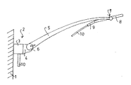
図1は、本発明に従ったシャワーヘッドのホルダおよび壁取付け具を大きく簡略化した側面図を示している。図示の実施例では、このシャワーヘッドのホルダは、壁1に取付けられている。図示の実施例の場合には例えば壁にボルト留めされるコンソール3の形の取付け備品2は、それを壁に取付けるように機能する。コンソール3の内部において、シャワーヘッドのホルダは、混合水栓からの水配管に接続される。アーム5は、コンソール3上の突起4の上においてピボット旋回される。そのピボット旋回軸は、紙の平面に対して水平且つ垂直である。取っ手6によって操作され得る止めネジは、アーム5を特定の角度位置にクランプする。アームは、取付け備品2において始端し、その遠端7において終端するようにして、壁から離れるように延在する。図1では何も詳細に示されていないシャワーヘッド8のためのホルダは、アーム5に対して、アームの遠端7の近傍において取付けられる。図示の実施例の事例では、シャワーヘッド8は、ディスク形状であり、シャワーヘッド8の平面から僅かに角度的にオフセットしたハンドグリップ9を有する。ハンドグリップ9の内部では、詳細には示されていないシャワーホース10が、ハンドグリップ9を貫通し、そこから自由に垂れ下がっている。シャワーホース10の他端は、取付け備品2に接続される。前述のように、アーム5は、水平方向軸の周りでピボット旋回され得るものであり、それは、上下に旋回されるとき壁に対して様々な角度位置を採ることが可能である。アーム5の角度運動範囲は、例えば180°である。
FIG. 1 shows a greatly simplified side view of a showerhead holder and wall fixture according to the present invention. In the embodiment shown, this showerhead holder is attached to the wall 1. In the case of the illustrated embodiment, the fixture 2 in the form of a console 3 bolted to the wall, for example, functions to attach it to the wall. Inside the console 3, the shower head holder is connected to the water pipe from the mixing faucet. The
図2は、図1に示された構成の概略図を示している。アーム5は、コンソール3に対するその取付け個所を僅かに越えて枝分かれして分岐しているが、アームの遠端7の近傍では互いに平行に形成される1対のフォークの歯11を形成し、そこでは、既述されているホルダ13が、それらのフォークの歯の先端12の間に設けられる。ホルダは、シャワーヘッド8を保持するものであり、これもまたフォークの歯の先端12の間に配置される。
FIG. 2 shows a schematic diagram of the configuration shown in FIG.
ホルダが詳細にどのように見えるかということは、図3に示された第1のサンプルの実施例から理解され得る。シャワーヘッド8のハウジングは、ディスク形状であり、略楕円形の外周を有する。その内面がシャワーヘッドのハウジングの外面に適合するように輪郭形成される1対の顎部14は、アーム5のフォークの歯11の内面上に配置されて、シャワーヘッド8を1種の型嵌めクランプで収容し、係合面によって発揮される力が上下に作用する。しかしながら、紙の平面に垂直な方向に沿ったクランピング作用は、締まり嵌めに拠るものである。クランピング顎部14の各々における間接的なクランピングまたは取っ手6によって操作され得る互いに対する1対のクランピング顎部14の張力付加のいずれかが、その目的のために利用されても良い。互いに対するクランピング顎部14の張力付加は、それらの分離がシャワーヘッド8のハウジングの対応する横方向寸法または直径よりも僅かに小さいと規定することによって獲得され得るものであり、それは、シャワーヘッドのハウジングが1対のクランピング顎部14の間に挿入されるときに紙の平面に垂直にそれらが張力を掛けられるように規定する。それらの張力付加は、結果として、アームの1対のフォークの歯11の変形によって引き起こされることになる。図3における紙の平面に垂直なクランピング顎部14の延長部は、かなり短めであり、それらは、図4において簡略的な形態で示されたように、対角的に対向するその2つの場所のみにおいて、且つその周囲の非常に短い部分にわたってのみ、シャワーヘッドのハウジングを把持することになるのである。
It can be seen from the first sample embodiment shown in FIG. 3 how the holder looks in detail. The housing of the
図5は、ホルダ上の1対の顎部14がベール15によって互いに結合され得る様式を示すものであり、該ベールは、シャワーヘッド8のハウジングの形状に適合されるか、或いはそれがハウジングの形状に整合することを許容するような様式で撓むようにして形成される。本質的に張力が掛かるベール15を採用することは、クランピング作用の増強を可能にする。
FIG. 5 shows the manner in which a pair of
クランピング顎部14の一方は、アームの1対のフォークの歯11の各々の先端12上において両者が自由に回転できるように取付けられ、ホルダは、シャワーヘッド8と共に、水平方向軸の周りでピボット旋回されても良い。図1に示された取っ手6と同様な拘束部材が、シャワーヘッドを特定の位置に係止する設備を提供する目的で設けられても良い。
One of the clamping
シャワーヘッドは、そのグリップ9によって把持され得るものであり、好ましくは壁に向かって紙の平面に垂直にホルダから引抜かれても良い。顎部14(図4をも参照)がシャワーヘッド8のハウジングの中央平面においてアーチ状の内面16を有するならば、ホルダ内におけるシャワーヘッドのハウジングの所定のラッチ保持は、シャワーヘッドのハウジングが当該場所においてそれがホルダ内に保持されることになると認知することを許容するような形状を有する必要なしで、生じることになる。シャワーヘッドがホルダから引抜かれるとき、それがシャワーヘッドのホルダ上に取付けられるものとして意図されているという視認可能な兆候は何も存在しない。
The showerhead can be gripped by its
図2は、シャワーヘッドが、そのホルダと共に、フォークの先端の間に取付けられる実施例を示している。当然ながら、そのようなホルダがフォークを構成しないアーム上に取付けられ得ると規定することもまた実行可能であり、その選択肢もまた、本発明によってカバーされる。その選択肢は、例えば、図示のようなホルダがアームの遠端の側面上に取付けられることを規定することによって実行されても良い。例えば、図2において、1対の歯11の一方が存在しないことも想像され得るのであり、その場合には、ホルダが残りのアームの一方の側面上に配置され、或いはそこに非対称的に配置される実施例が達成されるであろう。
FIG. 2 shows an embodiment in which the showerhead is mounted with its holder between the tips of the forks. Of course, it is also feasible to specify that such a holder can be mounted on an arm that does not constitute a fork, and that option is also covered by the present invention. The option may be implemented, for example, by providing that a holder as shown is mounted on the side of the distal end of the arm. For example, in FIG. 2 it can also be imagined that one of the pair of
当然ながら、例えば、張力付加部材15の中心をアームの遠端に取付けることもまた実行可能であり、その場合には、当然ながら、回転軸を組込むための設備が設けられても良いのである。
Of course, for example, it is also feasible to attach the center of the tensioning
1 壁
2 取付け備品
3 コンソール
4 突起
5 アーム
6 取っ手
7 遠端
8 シャワーヘッド
9 ハンドグリップ
10 シャワーホース
11 歯
12 歯の先端
13 ホルダ
14 顎部
1 Wall 2 Mounting Equipment 3 Console 4
Claims (12)
1.1 シャワーヘッド(8)のためのホルダを有し、
1.2 ホルダは、シャワーヘッド(8)を保持する目的のために設けられていて、シャワーヘッド(8)は、ホルダに保持されているときでもシャワー機能があり、
1.3 ホルダは、引抜き方向および差込み方向に沿った締嵌めによって機能し、
ホルダは、シャワーヘッド(8)のハウジングの外周を把持するように形成されており、
シャワーヘッド(8)のハウジングが、シャワーヘッド(8)のハウジングの形状に基づいて、ハウジング外周の把持される場所を認知され得ない形状になっていることを特徴とする、壁取付け具。A wall fixture for detachably installing a showerhead,
1.1 having a holder for the showerhead (8),
1.2 holder is provided for the purpose that holds the shower head (8), the shower head (8) has a shower function, even when it is held by the holder,
1.3 The holder functions by an interference fit along the pull-out direction and the insertion direction ,
The holder is formed so as to grip the outer periphery of the housing of the shower head (8),
Shower housing head (8), based on the shape of the housing of the shower head (8), characterized that you have a shape that can not be recognized where the gripping of the housing outer peripheral wall fixture.
Applications Claiming Priority (2)
| Application Number | Priority Date | Filing Date | Title |
|---|---|---|---|
| DE10260210A DE10260210A1 (en) | 2002-12-13 | 2002-12-13 | Holding arrangement for removably holding a showerhead comprises a holder for attaching to a point of the showerhead housing that is not discernible for a holder and acting in the release/insertion direction by a force-locking connection |
| PCT/EP2003/013056 WO2004055279A1 (en) | 2002-12-13 | 2003-11-21 | Wall mounting for a shower head |
Publications (2)
| Publication Number | Publication Date |
|---|---|
| JP2006509938A JP2006509938A (en) | 2006-03-23 |
| JP4477507B2 true JP4477507B2 (en) | 2010-06-09 |
Family
ID=32336538
Family Applications (1)
| Application Number | Title | Priority Date | Filing Date |
|---|---|---|---|
| JP2004559711A Expired - Fee Related JP4477507B2 (en) | 2002-12-13 | 2003-11-21 | Shower head wall fixture |
Country Status (9)
| Country | Link |
|---|---|
| US (1) | US8015632B2 (en) |
| EP (1) | EP1570135B1 (en) |
| JP (1) | JP4477507B2 (en) |
| CN (1) | CN100554603C (en) |
| AT (1) | ATE551475T1 (en) |
| AU (1) | AU2003285339A1 (en) |
| DE (1) | DE10260210A1 (en) |
| ES (1) | ES2382460T3 (en) |
| WO (1) | WO2004055279A1 (en) |
Families Citing this family (3)
| Publication number | Priority date | Publication date | Assignee | Title |
|---|---|---|---|---|
| US9146000B2 (en) * | 2013-06-04 | 2015-09-29 | Eli Zhadanov | Shaped water supplying extension arm |
| CN105805410A (en) * | 2016-05-03 | 2016-07-27 | 袁静 | Electric heating faucet fixing and adjusting rack |
| CN106284538B (en) * | 2016-08-20 | 2019-09-06 | 厦门建霖健康家居股份有限公司 | A kind of wall base shower and its application method |
Family Cites Families (21)
| Publication number | Priority date | Publication date | Assignee | Title |
|---|---|---|---|---|
| US1078283A (en) * | 1911-04-07 | 1913-11-11 | F O Hilfiker Co | Toilet implement. |
| US2276779A (en) * | 1939-08-14 | 1942-03-17 | Isenberg Stanley | Supporting bracket for spray devices |
| FR1042242A (en) | 1951-09-17 | 1953-10-29 | Shower head holder | |
| DE945116C (en) | 1954-03-21 | 1956-06-28 | Junkers & Co | Holder for height-adjustable hose showers |
| CH340460A (en) * | 1957-12-27 | 1959-08-15 | Ducommun Pierre | Articulated support for a shower comprising a handle connected to a flexible hose |
| FR2197395A5 (en) * | 1972-08-23 | 1974-03-22 | Beroudiaux Mich L | |
| US3820716A (en) * | 1973-01-11 | 1974-06-28 | Bowles Fluidics Corp | Fluidic oscillator for providing dynamic liquid spray patterns |
| US4072397A (en) * | 1975-09-05 | 1978-02-07 | Ross Thomas H | Mirror attachment for shower head |
| US4091998A (en) * | 1976-11-16 | 1978-05-30 | Associated Mills, Inc. | Retainer clamp |
| US4131232A (en) * | 1977-05-23 | 1978-12-26 | Pollinzi Angeline D | Automatic shower dispenser |
| IT8220904V0 (en) * | 1982-02-19 | 1982-02-19 | Stella Rubinetterie Spa | GROUP OF WATER DISPENSING FOR SHOWERS AND SIMILAR. |
| DE8916188U1 (en) | 1989-09-20 | 1994-10-27 | Scheffer Franz Armaturen | Holding device for a hand shower |
| DE3931304C2 (en) * | 1989-09-20 | 1995-02-16 | Scheffer Franz Armaturen | Holding device for a hand shower |
| US5215258A (en) * | 1991-08-06 | 1993-06-01 | Pollenex Corporation | Active shower head |
| JPH0881986A (en) | 1994-09-09 | 1996-03-26 | Kitamura Gokin Seisakusho:Kk | Shower hanger |
| DE29813597U1 (en) * | 1998-07-17 | 1998-10-22 | Schoenborn Klaus | Shower system |
| DE19942853A1 (en) | 1999-09-08 | 2001-04-12 | Hueppe Gmbh & Co | Shower head arrangement |
| DE10048987B4 (en) * | 2000-09-27 | 2014-07-17 | Grohe Ag | shower device |
| DE10051452B4 (en) * | 2000-10-17 | 2006-12-14 | Hansgrohe Ag | Arrangement for attaching a shower |
| CA103285S (en) * | 2002-12-12 | 2005-01-17 | Hansgrohe Ag | Handheld shower head |
| US7360723B2 (en) * | 2003-11-06 | 2008-04-22 | Moty Lev | Showerhead system with integrated handle |
-
2002
- 2002-12-13 DE DE10260210A patent/DE10260210A1/en not_active Withdrawn
-
2003
- 2003-11-21 JP JP2004559711A patent/JP4477507B2/en not_active Expired - Fee Related
- 2003-11-21 WO PCT/EP2003/013056 patent/WO2004055279A1/en active Application Filing
- 2003-11-21 CN CNB2003801058616A patent/CN100554603C/en not_active Expired - Fee Related
- 2003-11-21 AU AU2003285339A patent/AU2003285339A1/en not_active Abandoned
- 2003-11-21 ES ES03778327T patent/ES2382460T3/en not_active Expired - Lifetime
- 2003-11-21 AT AT03778327T patent/ATE551475T1/en active
- 2003-11-21 EP EP03778327A patent/EP1570135B1/en not_active Expired - Lifetime
- 2003-11-21 US US10/538,671 patent/US8015632B2/en not_active Expired - Fee Related
Also Published As
| Publication number | Publication date |
|---|---|
| WO2004055279A1 (en) | 2004-07-01 |
| ES2382460T3 (en) | 2012-06-08 |
| CN1726327A (en) | 2006-01-25 |
| ATE551475T1 (en) | 2012-04-15 |
| US20060230521A1 (en) | 2006-10-19 |
| US8015632B2 (en) | 2011-09-13 |
| EP1570135B1 (en) | 2012-03-28 |
| EP1570135A1 (en) | 2005-09-07 |
| DE10260210A1 (en) | 2004-06-24 |
| CN100554603C (en) | 2009-10-28 |
| AU2003285339A1 (en) | 2004-07-09 |
| JP2006509938A (en) | 2006-03-23 |
Similar Documents
| Publication | Publication Date | Title |
|---|---|---|
| US6154539A (en) | Headset adapter for microphone and earpiece | |
| US6671930B2 (en) | Adjustable tool mount apparatus and specialized tool handle thereof | |
| JP2003170364A (en) | Adapter for remote controlled pliers | |
| KR20130005749U (en) | Clamp for pipe | |
| US8720070B2 (en) | Pipe peeler | |
| JP2013027057A (en) | Electric line anchoring system | |
| JP4477507B2 (en) | Shower head wall fixture | |
| JP2014176144A (en) | Wire stripper | |
| JP2011031383A (en) | Sander | |
| JP5268446B2 (en) | Transmission line binding device | |
| JP2007210039A (en) | Gripping jig | |
| JP2006349183A (en) | Rope tensioner | |
| JP4477508B2 (en) | Shower support | |
| EP2756819B1 (en) | Interdental cleaning device | |
| AU2002229628A1 (en) | Anchoring device for a vehicle seat that can be installed and removed without the use of tools | |
| JP2000261922A (en) | Hot-line remote working apparatus | |
| JP2016135013A (en) | Protective tube holder | |
| JP2004357407A (en) | Wire stretcher | |
| JP5730723B2 (en) | Temporary power transmission device for PC cutout | |
| US5752494A (en) | Band adapter for slingshot | |
| CN209154071U (en) | A kind of curved root canal adapter | |
| JP2008194822A (en) | Adapter used for pliers for remote control | |
| JP3127190U (en) | Adhesive tape cutter | |
| KR200173541Y1 (en) | A handle removing device of a welding machine holder | |
| JP2603457Y2 (en) | Grip extension for hand held massage machine |
Legal Events
| Date | Code | Title | Description |
|---|---|---|---|
| A621 | Written request for application examination |
Free format text: JAPANESE INTERMEDIATE CODE: A621 Effective date: 20060523 |
|
| A131 | Notification of reasons for refusal |
Free format text: JAPANESE INTERMEDIATE CODE: A131 Effective date: 20090714 |
|
| A601 | Written request for extension of time |
Free format text: JAPANESE INTERMEDIATE CODE: A601 Effective date: 20091002 |
|
| A601 | Written request for extension of time |
Free format text: JAPANESE INTERMEDIATE CODE: A601 Effective date: 20091006 |
|
| A602 | Written permission of extension of time |
Free format text: JAPANESE INTERMEDIATE CODE: A602 Effective date: 20091009 |
|
| A601 | Written request for extension of time |
Free format text: JAPANESE INTERMEDIATE CODE: A601 Effective date: 20091014 |
|
| A602 | Written permission of extension of time |
Free format text: JAPANESE INTERMEDIATE CODE: A602 Effective date: 20091014 |
|
| A602 | Written permission of extension of time |
Free format text: JAPANESE INTERMEDIATE CODE: A602 Effective date: 20091021 |
|
| A521 | Request for written amendment filed |
Free format text: JAPANESE INTERMEDIATE CODE: A523 Effective date: 20091228 |
|
| TRDD | Decision of grant or rejection written | ||
| A01 | Written decision to grant a patent or to grant a registration (utility model) |
Free format text: JAPANESE INTERMEDIATE CODE: A01 Effective date: 20100309 |
|
| A01 | Written decision to grant a patent or to grant a registration (utility model) |
Free format text: JAPANESE INTERMEDIATE CODE: A01 |
|
| A61 | First payment of annual fees (during grant procedure) |
Free format text: JAPANESE INTERMEDIATE CODE: A61 Effective date: 20100311 |
|
| R150 | Certificate of patent or registration of utility model |
Free format text: JAPANESE INTERMEDIATE CODE: R150 |
|
| FPAY | Renewal fee payment (event date is renewal date of database) |
Free format text: PAYMENT UNTIL: 20130319 Year of fee payment: 3 |
|
| FPAY | Renewal fee payment (event date is renewal date of database) |
Free format text: PAYMENT UNTIL: 20130319 Year of fee payment: 3 |
|
| FPAY | Renewal fee payment (event date is renewal date of database) |
Free format text: PAYMENT UNTIL: 20140319 Year of fee payment: 4 |
|
| R250 | Receipt of annual fees |
Free format text: JAPANESE INTERMEDIATE CODE: R250 |
|
| R250 | Receipt of annual fees |
Free format text: JAPANESE INTERMEDIATE CODE: R250 |
|
| R250 | Receipt of annual fees |
Free format text: JAPANESE INTERMEDIATE CODE: R250 |
|
| LAPS | Cancellation because of no payment of annual fees |