JP4474635B2 - Monitoring system - Google Patents
Monitoring system Download PDFInfo
- Publication number
- JP4474635B2 JP4474635B2 JP2003376200A JP2003376200A JP4474635B2 JP 4474635 B2 JP4474635 B2 JP 4474635B2 JP 2003376200 A JP2003376200 A JP 2003376200A JP 2003376200 A JP2003376200 A JP 2003376200A JP 4474635 B2 JP4474635 B2 JP 4474635B2
- Authority
- JP
- Japan
- Prior art keywords
- tag
- antenna
- monitoring
- frame
- machine frame
- Prior art date
- Legal status (The legal status is an assumption and is not a legal conclusion. Google has not performed a legal analysis and makes no representation as to the accuracy of the status listed.)
- Expired - Fee Related
Links
- 238000012544 monitoring process Methods 0.000 title claims description 77
- 238000004891 communication Methods 0.000 claims description 45
- 238000003860 storage Methods 0.000 claims description 31
- 230000002159 abnormal effect Effects 0.000 claims description 18
- 230000007246 mechanism Effects 0.000 description 10
- 238000000034 method Methods 0.000 description 10
- 230000005540 biological transmission Effects 0.000 description 9
- 238000009434 installation Methods 0.000 description 7
- 230000008859 change Effects 0.000 description 6
- 238000005520 cutting process Methods 0.000 description 6
- 229920003002 synthetic resin Polymers 0.000 description 6
- 239000000057 synthetic resin Substances 0.000 description 6
- 210000000078 claw Anatomy 0.000 description 5
- 238000010586 diagram Methods 0.000 description 5
- 230000000694 effects Effects 0.000 description 5
- 238000003780 insertion Methods 0.000 description 5
- 230000037431 insertion Effects 0.000 description 5
- 239000011521 glass Substances 0.000 description 4
- 230000008569 process Effects 0.000 description 4
- 230000005856 abnormality Effects 0.000 description 3
- 230000002265 prevention Effects 0.000 description 3
- 239000000853 adhesive Substances 0.000 description 2
- 230000001070 adhesive effect Effects 0.000 description 2
- 239000012790 adhesive layer Substances 0.000 description 2
- 230000008901 benefit Effects 0.000 description 2
- 239000004973 liquid crystal related substance Substances 0.000 description 2
- 230000004048 modification Effects 0.000 description 2
- 238000012986 modification Methods 0.000 description 2
- 239000000758 substrate Substances 0.000 description 2
- 238000004026 adhesive bonding Methods 0.000 description 1
- 238000005452 bending Methods 0.000 description 1
- 239000011248 coating agent Substances 0.000 description 1
- 238000000576 coating method Methods 0.000 description 1
- 230000008878 coupling Effects 0.000 description 1
- 238000010168 coupling process Methods 0.000 description 1
- 238000005859 coupling reaction Methods 0.000 description 1
- 238000010304 firing Methods 0.000 description 1
- 238000004519 manufacturing process Methods 0.000 description 1
- 239000000463 material Substances 0.000 description 1
- 239000002184 metal Substances 0.000 description 1
- 230000003287 optical effect Effects 0.000 description 1
- 230000000737 periodic effect Effects 0.000 description 1
- 229920005989 resin Polymers 0.000 description 1
- 239000011347 resin Substances 0.000 description 1
- 230000004044 response Effects 0.000 description 1
Images

Landscapes
- Pinball Game Machines (AREA)
Description
本発明は、パチンコ機、スロットマシーン等の遊技機を監視可能な監視システムに関するものである。 The present invention, pachinko machines, in which relates the gaming machine such as a slot machine enables monitoring system monitoring.
従来より、例えば、機枠、遊技枠及び前面枠等を備えたパチンコ機等においては、特定の遊技者が不正に利益を得ようとするために、遊技枠や前面枠等を不正に開放したり、遊技内容を制御するLSIやROM等が交換するといった不正行為が後を絶たない。そこで、そのような不正行為を防止するために、特許文献1に開示されているような遊技用装置が考案されている。 Conventionally, for example, in a pachinko machine equipped with a machine frame, a game frame, a front frame, etc., in order to allow a specific player to gain profits illegally, the game frame, the front frame, etc. are illegally opened. Or illegal actions such as replacement of LSIs and ROMs for controlling game contents are steadily occurring. Therefore, in order to prevent such illegal acts, a gaming device as disclosed in Patent Document 1 has been devised.
特許文献1に開示されている遊技用装置は、LSIやROM等が収納された制御装置の収納ケースの表面に、固有の識別情報を記憶したICタグを貼着するとともに、ID読取装置を各遊技機が配設された遊技機設置島に設置し、ICタグとID読取装置との間でRFID通信を行うことによって、ICタグの識別情報を一定の周期毎に読み取り、その識別情報を外部の集中管理手段へと送信し、集中管理手段にて送信されてきた識別情報が正しいか否かを確認するようにしたものである。 The gaming device disclosed in Patent Document 1 has an IC tag storing unique identification information attached to the surface of a storage case of a control device in which LSI, ROM, etc. are stored, It is installed on the gaming machine installation island where the gaming machine is arranged, and RFID communication is performed between the IC tag and the ID reader, thereby reading the identification information of the IC tag at regular intervals, and the identification information is externally transmitted. To the centralized management means, and it is confirmed whether or not the identification information transmitted by the centralized management means is correct.
しかしながら、特許文献1に開示されているようなID読取装置を別個に設ける構成を、遊技枠や前面枠等の不正開放を検知するために適用するとなると、ID読取装置の設置場所の確保が困難である等の様々な問題点を有することになる。
そこで、遊技枠や前面枠等の不正開放を検知可能とすべく、ICタグと対峙する位置にICタグとの間でRFID通信可能なアンテナを取り付けたものも考案されている。しかしながら、ICタグとアンテナとの間で無線通信を行う場合、遊技機の形状(各部材の凹凸等)により、ICタグとアンテナとを取り付け可能な位置(無線通信可能となる位置)がある程度決まってしまう。したがって、不正行為に対してより効果的な取付位置や、配線の都合や他の部材との兼ね合い等を考慮した場合により適切となる取付位置が他にあるにもかかわらず、無線通信可能となる位置が他にないという理由だけで、ICタグとアンテナとをあまりメリットのない位置に取り付けなければならないといった問題があった。更に、遊技機の形状(各部材の凹凸等)はメーカーによって多種多様であり、ICタグとアンテナとを後付けする場合等には、上記問題がより顕著となり、場合によってはICタグとアンテナとを設置できないこともあった。
However, when a configuration in which an ID reader is separately provided as disclosed in Patent Document 1 is applied to detect unauthorized opening of a game frame, a front frame, etc., it is difficult to secure an installation location of the ID reader. There are various problems such as.
Therefore, in order to be able to detect unauthorized opening of a game frame, a front frame, or the like, an antenna in which an RFID communication with the IC tag is attached at a position facing the IC tag has been devised. However, when wireless communication is performed between the IC tag and the antenna, the position where the IC tag and the antenna can be attached (position where wireless communication is possible) is determined to some extent depending on the shape of the gaming machine (unevenness of each member, etc.). End up. Therefore, wireless communication is possible even though there are other more suitable mounting positions in consideration of the mounting position more effective against fraud, the convenience of wiring, and the balance with other members. There was a problem that the IC tag and the antenna had to be attached at a position where there was not much merit just because there was no other position. Furthermore, the shape of the gaming machine (unevenness of each member, etc.) varies depending on the manufacturer, and the above problem becomes more noticeable when the IC tag and the antenna are retrofitted, and in some cases the IC tag and the antenna are Sometimes it could not be installed.
そこで、本発明は、上記従来の遊技機が有する問題点を解消し、遊技機の形状にとらわれることなくICタグとアンテナとを任意の位置に取り付けることが可能であるとともに、従来の遊技機にも容易に取り付け可能な監視システムを提供しようとするものである。 Therefore, the present invention solves the above-mentioned problems of the conventional gaming machine, allows the IC tag and the antenna to be attached to arbitrary positions without being restricted by the shape of the gaming machine, and is added to the conventional gaming machine. it is also intended to provide a monitoring system that can be installed easily.
上記目的を達成するために、請求項1に記載の発明は、少なくとも一方の移動によって相対距離が変化する第一の部材と第二の部材とからなる可動部を少なくとも一組有する遊技機に用いられ、前記第一の部材あるいは第二の部材のどちらか一方の部材に設けられる呼出波を受信すると記憶している固有の識別情報を含む反射波を出力するICタグと、他方の部材に設けられ、前記ICタグに対して呼出波を送信し、前記ICタグからの反射波を受信するアンテナと、前記ICタグとアンテナとの間における非接触通信により前記可動部の監視を行う監視手段と、前記ICタグに記憶されている固有の識別情報及び監視手段による監視結果を含む監視履歴情報を記憶する記憶手段とを備えた監視制御装置と、
からなる監視システムであって、前記ICタグ或いは前記アンテナの少なくとも一方を、枠体と各枠体間を接続する接続部とからなる分断部が多段に積み重ねられた補助具に設置しており、該補助具から任意の数の分断部を分断させることにより、前記ICタグと前記アンテナとの間の距離を調節可能としたことを特徴とするものである。
請求項2に記載の発明は、前記補助具が、各分断部同士を着脱自在とした組み立て式の補助具であるとともに、前記接続部の長さが異なる複数種類の分断部を多段に積み重ねてなることを特徴とするものである。
請求項3に記載の発明は、作業効率の向上をはかるべく、前記補助具は、設置されたICタグ或いはアンテナの抜け止めを防止する抜け止め防止手段を備えたものであることを特徴とするものである。
請求項4に記載の発明は、より精度の高い監視を行うことが可能な監視システムとするために、前記監視制御装置は、タイマを備えているとともに、前記監視手段において、前記アンテナを介して呼出波を送信してから所定時間内に前記ICタグからの反射波を受信し、且つ受信した反射波に含まれる識別情報が前記記憶手段に予め記憶されているもの識別情報と一致した場合のみを正常と判断し、それ以外の場合を異常と判断し、異常と判断した場合には前記監視履歴情報を異常と判断した時刻に関連づけて記憶することを特徴とするものである。
In order to achieve the above object, the invention according to claim 1 is used in a gaming machine having at least one set of movable parts each composed of a first member and a second member whose relative distance changes by at least one movement. An IC tag that outputs a reflected wave including unique identification information stored when receiving a ringing wave provided on one of the first member and the second member, and provided on the other member An antenna that transmits a ringing wave to the IC tag and receives a reflected wave from the IC tag, and a monitoring unit that monitors the movable part by non-contact communication between the IC tag and the antenna; A monitoring control device comprising storage means for storing monitoring identification information including unique identification information stored in the IC tag and monitoring results by the monitoring means;
A monitoring system comprising: at least one of the IC tag or the antenna is installed in an auxiliary tool in which divided parts composed of a frame body and a connection part connecting between the frame bodies are stacked in multiple stages ; The distance between the IC tag and the antenna can be adjusted by dividing an arbitrary number of dividing portions from the auxiliary tool.
In the invention according to
The invention described in
According to a fourth aspect of the present invention, in order to provide a monitoring system capable of performing monitoring with higher accuracy, the monitoring control device includes a timer, and the monitoring means includes the antenna via the antenna. Only when the reflected wave from the IC tag is received within a predetermined time after transmitting the calling wave, and the identification information included in the received reflected wave matches the identification information stored in advance in the storage means was determined to be normal, it is determined otherwise abnormal, if it is determined that the abnormality is Ru der what and to store in association with the time it is determined that the abnormality the monitoring history information.
本発明に係る監視システムによれば、従来のようにICタグ及びアンテナをどちらも遊技機本体に直接固着する構成では非接触通信不可能な位置(たとえば、距離が離れすぎているような位置)であっても、補助具を利用することにより非接触通信可能とし得るため、設置される遊技機の形状にとらわれることなく任意の位置にて非接触通信を行うことができる。つまり、従来より遊技場ホール等で使用されている様々なタイプの遊技機に設置することができる。
さらに、、補助具を、枠体と各枠体間を接続する接続部とからなる分断部を多段に積み重ねることにより形成したため、所定の数の分断部を分断させることにより、容易にその高さを調節することができる。つまり、アンテナとICタグとの間の距離を非接触通信可能な所定の距離に容易に調節することができる。
また、請求項2に記載の発明によれば、補助具が、各分断部同士を着脱自在とした組み立て式の補助具であるとともに、接続部の長さが異なる複数種類の分断部を多段に積み重ねてなるため、アンテナとICタグとの間の距離を微調整することができる。
さらに、請求項3に記載の発明によれば、補助具には設置されたアンテナ或いはICタグの抜け止めを防止するための抜け止め防止手段が設けられているため、補助具を遊技機等に設置する際等にアンテナ或いはICタグが抜け落ちてしまうことがなく、非常に作業性に優れた監視システムとなっている。
さらにまた、請求項4に記載の発明によれば、ICタグとアンテナとの間で行う非接触通信において、アンテナを介して呼出波を送信してから所定時間内にICタグからの反射波を受信し、且つ受信した反射波に含まれる識別情報が記憶手段に予め記憶されているもの識別情報と一致した場合のみを正常と判断し、それ以外の場合を異常と判断している。そのため、たとえば不正開放や不正交換といった行為を確実に検知することが可能となっている。加えて、監視制御装置は、時刻を計時するためのタイマを備えており、異常と判断した場合に、監視履歴情報を異常と判断した時刻に関連づけて記憶するため、上述したような不正行為をリアルタイムで検知することが可能である。
According to the monitoring system of the present invention, a position where non-contact communication is not possible with a configuration in which both the IC tag and the antenna are directly fixed to the gaming machine body as in the past (for example, a position where the distance is too far). Even so, it is possible to perform non-contact communication by using an auxiliary tool, so that non-contact communication can be performed at an arbitrary position without being limited by the shape of the installed gaming machine. In other words, it can be installed in various types of gaming machines that have been conventionally used in game halls and the like.
Moreover, the aid, since the cutting portion comprising a connecting portion for connecting the frame and the frame formed by Rukoto stacked in multiple stages, by dividing the divided portion of the predetermined number, easily its high Can be adjusted. That is, the distance between the antenna and the IC tag can be easily adjusted to a predetermined distance that allows non-contact communication.
According to the invention described in
Further, according to the invention described in
Furthermore , according to the invention described in
以下、本発明に係る遊技機の一実施形態であるパチンコ機について、図面に基づき、次の目次の順序にしたがって、詳細に説明する。
(1)実施例の監視システム及びパチンコ機の概要
(2)実施例の監視システム及びパチンコ機の構造
(3)実施例の監視システム及びパチンコ機の動作内容
(4)実施例の監視システム及びパチンコ機の効果
(5)本発明の変更例の説明
Hereinafter, a pachinko machine that is an embodiment of a gaming machine according to the present invention will be described in detail according to the order of the following table of contents based on the drawings.
(1) Overview of monitoring system and pachinko machine of embodiment (2) Structure of monitoring system and pachinko machine of embodiment (3) Monitoring system of embodiment and operation contents of pachinko machine (4) Monitoring system and pachinko machine of embodiment Effects of machine (5) Description of modification of the present invention
(1)実施例の監視システム及びパチンコ機の概要
本実施例に係るパチンコ機は、パチンコ機本体を支持する機枠(可動部)に、ミドル枠(可動部)が着脱自在に取り付けられているとともに、そのミドル枠に、ガラス板等が設置された前面枠(可動部)、供給皿、貯留皿等が着脱自在に取り付けられているものである。以下、ミドル枠及びミドル枠に取り付けられている前面枠等を合わせて遊技枠(可動部)とする。
また、遊技枠の背面側は機構板が取り付けられた状態となっており、該機構板に、遊技内容に関する動作を制御するためのメイン制御基板を収納したメイン基板収納ケース(可動部)、パチンコ機の監視動作を制御するとともに監視履歴情報を記憶する監視制御装置、及び遊技球払出装置等が設置されている。
(1) Overview of Example Monitoring System and Pachinko Machine In the pachinko machine according to this example, a middle frame (movable part) is detachably attached to a machine frame (movable part) that supports the main body of the pachinko machine. At the same time, a front frame (movable part) on which a glass plate or the like is installed, a supply tray, a storage tray, and the like are detachably attached to the middle frame. Hereinafter, the middle frame and the front frame attached to the middle frame are collectively referred to as a game frame (movable part).
In addition, a mechanism board is attached to the back side of the game frame, and a main board storage case (movable part) that houses a main control board for controlling operations related to game contents, a pachinko, A monitoring control device that controls the monitoring operation of the machine and stores monitoring history information, a game ball payout device, and the like are installed.
さらに、機枠に対する遊技枠の開閉状況を監視するために、機枠にはRFID(Radio Frequency identification)通信(非接触通信)可能で固有の識別情報を記憶した機枠タグ(ICタグ)が取り付けられている一方、遊技枠側には機枠タグとRFID通信可能な機枠アンテナ(アンテナ)が挿入(設置)された階段状のアンテナ台(補助具)が設置されている。そして、機枠タグと機枠アンテナとの間においてRFID通信を行い、その通信の可否によって、遊技枠の開閉状況を監視するようになっている。この機枠タグと機枠アンテナとの間で行われるRFID通信は常時(24時間)行われており、遊技枠の開閉状況をリアルタイムで監視している。また、機枠タグに記憶されている固有の識別情報とは、その名の通りタグ毎に固有な唯一無二のものである。
さらにまた、機枠アンテナは監視制御装置に接続されている。監視制御装置は、機枠タグと機枠アンテナとの間で行われるRFID通信を制御する監視手段、パチンコ機が設置されたホールで使用される識別情報を記憶した記憶手段、及び時刻を計時するタイマ等を備えている。なお、識別情報は監視制御装置に予め登録されている。このような監視制御装置では、機枠タグと機枠アンテナとの間におけるRFID通信を制御するとともに、RFID通信の通信状態の監視を行っており、通信不可となった場合等には監視履歴情報として通信不可となった時刻等を記憶手段に記憶する。
Furthermore, in order to monitor the opening / closing state of the game frame with respect to the machine frame, a machine frame tag (IC tag) storing RFID (Radio Frequency identification) communication (non-contact communication) and storing unique identification information is attached to the machine frame. On the other hand, on the game frame side, a stepped antenna base (auxiliary tool) into which a machine frame antenna (antenna) capable of RFID communication with the machine frame tag is inserted (installed) is installed. Then, RFID communication is performed between the machine frame tag and the machine frame antenna, and the open / close state of the game frame is monitored depending on whether the communication is possible. RFID communication performed between the machine frame tag and the machine frame antenna is always performed (24 hours), and the open / close state of the game frame is monitored in real time. Further, the unique identification information stored in the machine frame tag is unique and unique to each tag as its name suggests.
Furthermore, the machine frame antenna is connected to the monitoring control device. The monitoring and control device is a monitoring unit that controls RFID communication performed between the machine frame tag and the machine frame antenna, a storage unit that stores identification information used in a hall in which the pachinko machine is installed, and clocks time. A timer is provided. The identification information is registered in advance in the monitoring control device. In such a monitoring and control apparatus, the RFID communication between the machine frame tag and the machine frame antenna is controlled, and the communication state of the RFID communication is monitored. The time when communication is disabled is stored in the storage means.
(2)実施例の監視システム及びパチンコ機の構造
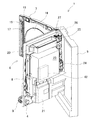
図1は、実施例のパチンコ機1を正面から見た図であり、図2は、遊技枠6及び前面枠7を片開きにし、パチンコ機1の遊技枠6の後面を示した説明図である。
パチンコ機1は、その周囲を機枠5によって支持されたものであって、機枠5の前面には、金属板を折り曲げ形成したミドル枠8が、左端縁(前方から見て)を軸として着脱自在に蝶着されている。そして、ミドル枠8の前面側であってパチンコ機1の中央よりやや上側には、略正方形の遊技盤2が設けられているとともに、その遊技盤2を覆うように前面枠7が左端縁(前方から見て)を軸として着脱自在に蝶着されている。また、前面枠7の下方には、発射装置4に遊技球を供給するための供給皿10、及び供給皿10から溢れた遊技球を貯留するための貯留皿11が設置されている。さらに、供給皿10と貯留皿11との間には、効果音を発生させるためのスピーカ12が設けられており、貯留皿11の右側(前方から見て)には、発射装置4を操作するための発射ハンドル9が取り付けられている。
(2) Structure of the monitoring system and the pachinko machine of the embodiment FIG. 1 is a view of the pachinko machine 1 of the embodiment as viewed from the front, and FIG. 2 shows the pachinko machine with the
The pachinko machine 1 is supported by the
また、遊技盤2の前面には、誘導レールによって囲まれた略円形の遊技領域3が設けられている。遊技領域3の略中央には、図柄表示装置13が設けられており、液晶画面14に種々の動画やメッセージ等を表示することができるようになっている。さらに、図柄表示装置13の下側には図柄始動口15が設けられており、その図柄始動口15の下側には、扉部材(可動部)を開閉させる大入賞装置16が設けられている。加えて、遊技領域3には、遊技球の落下に変化をもたせるために多数の障害釘や、風車等の遊技部材、及び遊技性を向上させるための種々のランプ等が設置されている。
一方、遊技盤2を覆うように設置される前面枠7は、フレーム17に2枚のガラス板(図示せず)が嵌め込まれたものである。フレーム17の中央には円形の遊技窓18が穿設されており、フレーム17の後側の周縁際には、ガラス板を嵌め込むための2列の嵌合溝19、19が設けられている。そして、遊技領域3の前方を内側のガラス板によって閉塞することによって偏平な円柱状の遊技空間を形成しており、遊技球が流下可能になっている。
以下、ミドル枠8、及びミドル枠8に取り付けられた遊技盤2や前面枠7等をあわせて遊技枠6と称す。
In addition, a substantially
On the other hand, the
Hereinafter, the
遊技枠6の後面側は、ミドル枠8に機構板20が設置された状態となっており、機構板20には、メイン基板収納ケース21、後述するリーダ/ライタユニット(以下、R/Wユニットとする)42等を覆うセンターカバー23、遊技球タンク25、及び賞品球や貸球を払い出すための遊技球払出装置24等が設置されている。メイン基板収納ケース21は左下方(後面側から見て)に設置されており、パチンコ機1の遊技内容に関する動作を制御するためのメイン制御基板を収納している。ここで、パチンコ機1の遊技内容に関する動作とは、遊技球の払い出し動作や、遊技者にとって有利な「大当たり状態」を生起させるか否かの「抽選」等の各種の動作(すなわち、遊技者の利益に直接的に関わる動作)のことである。
また、図2に示されているように、遊技球タンク25の右側(後面側から見て)には、RFID通信を行う機枠アンテナ26を挿入された階段状のアンテナ台27が、機枠アンテナ26を上方へ向けた状態で取り付けられている。一方、機枠5の上面内側であって、遊技枠6を機枠5に対して閉じた際に、機枠アンテナ26と対峙する箇所には、機枠アンテナ26との間でRFID通信を行う機枠タグ28が固着されている。
The rear side of the
Further, as shown in FIG. 2, on the right side (viewed from the rear side) of the
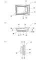
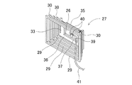
図3(a)〜(c)は、それぞれアンテナ台27の平面図、背面図及び右側面図である。また、図4(a)は該アンテナ台27を上方側から見た斜視図であり、図4(b)はアンテナ台27を下方側から見た斜視図である。
アンテナ台27は、合成樹脂により一体成形されたものであって、略長方形状に形成された枠体(分断部)29の四隅に同じ高さの接続部(分断部)30、30・・を備えたものを、枠体29が全て水平面に平行となるように多段に積み重ねたような形状となっている。尚、枠体29及び接続部30は全て一辺約2mmの断面正方形の部材であって、一段の高さは枠体29の厚さと接続部30の長さとを合わせて4mmに形成されている。また、接続部30、30・・は全て、下段の枠体29上から上方へと突設されている。また、図3(a)に示されているように、上段へといくに従って、枠体29が一回りずつ小さな長方形となるように形成されており、アンテナ台27は階段状となっている。このように形成されたアンテナ台27は、枠体29を設置面に接地させた状態で取り付けられる。さらに、ニッパ等の切断工具を用いれば、枠体29と接続部30、30・・との接続を容易に切断する(分断する)ことが可能となっており、任意の高さで枠体29と接続部30、30とを切断することでアンテナ台27の高さを4mm単位で調節することができるようになっている。尚、本実施例においては5段に形成されたものを用いている。
3A to 3C are a plan view, a rear view, and a right side view of the
The
一方、アンテナ台27の最上段には、右端(図3(a)において)に切り欠き部34を設けられた天板35と、中央に窓部37を設けられた裏板36とが設けられている。また、裏板36の窓部37内であって天板35の切り欠き部34と対峙する位置には、先端に矢尻状の係止爪(抜け止め防止手段)32を備えた係止片(抜け止め防止手段)33が突設されている。該係止片33も合成樹脂により形成されているため、係止片33は弾性を有している。また、天板35と裏板36との間は、一端(図3(a)において上側)を除いて閉塞されており、開口側から機枠アンテナ26を挿入可能な挿入部31が形成されている。
そして、挿入部31に後述する機枠アンテナ26を挿入したい場合には、係止片33を後方(図3(a)において紙面から裏面へと向かう方向)へ押し込みながら、機枠アンテナ26を挿入すればよい。機枠アンテナ26を完全に挿入すると、係止片33が元の状態へと戻り、機枠アンテナ26は、係止片33の先端に設けられた係止爪32によって係止された状態となる。一方、機枠アンテナ26を取り出したい場合には、係止爪32を後方へと押し込み、機枠アンテナ26との係合を解除した状態で、挿入部31の開口側を下に向けたり、裏板36の窓部37から指で機枠アンテナ26を押し出したりすればよい。
On the other hand, a
When the machine frame antenna 26 (described later) is to be inserted into the
ここで、このように形成されたアンテナ台27を所定位置へと設置する場合の設置手順を説明する。
まず、遊技枠6を機枠5に対して閉じた際に、機枠5に固着された機枠タグ28に対して機枠アンテナ26が略対峙した状態となるような位置を特定する。次に機枠アンテナ26をアンテナ台27に挿入させ、特定した位置にアンテナ台27を設置する。このとき、機枠タグ28と機枠アンテナ26との間の距離がRFID通信可能な所定の距離となるようにアンテナ台27の高さ調節が必要な場合には、アンテナ台27の所定の段の接続部30、30・・をニッパ等の切断工具を用いて枠体29から切り離すことで、アンテナ台27の高さを調節すればよい(図2では、下2段を切断したものを設置している)。
Here, an installation procedure in the case where the
First, when the
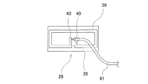
図5は、アンテナ台27に挿入される機枠アンテナ26を正面から見た図であり、図6は、該機枠アンテナ26をアンテナ台27に挿入した状態を示す説明図である。
機枠アンテナ26は、上述したように機枠タグ28との間でRFID通信を行うものであり、基板38の表面に送受信回路39を渦巻き状に形成したものを、合成樹脂等によりコーティングしたものである。そして、送受信回路39の両端縁の端子40、40に同軸ケーブル41が接続されている。
この機枠アンテナ26は、上述したようにアンテナ台27に挿入されるものであり、図6に示されているように同軸ケーブル41が接続されている面がアンテナ台27の下段側となるように挿入されている。そして、同軸ケーブル41は、裏板36に設けられた窓部37を挿通させて、R/Wユニット42へと接続されており、R/Wユニット42からの指令によって、送受信回路39から所定の周波数の呼出波を送信可能となっている。
FIG. 5 is a view of the
The
The
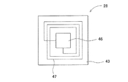
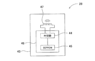
図7は、機枠アンテナ26とRFID通信可能な機枠タグ28の外観を示した説明図であり、図8は機枠タグ28の制御機構を示したブロック図である。
機枠タグ28は、合成樹脂で形成された薄い長方形状のプリント基板43上に、RF回路44とEEPROM45とを一体にしたICチップ46、及び渦巻き状に形成された送受信回路47を設けたものであり、RF回路44にEEPROM45と送受信回路47とが接続された状態となっている。そして、EEPROM45の上書消去禁止区域には、機枠タグ28を他のICタグと識別するためのIDコード等の識別情報が記憶されている。そして、このように形成された機枠タグ28は、上述したように機枠5の上面裏側に強固に固着されている。
FIG. 7 is an explanatory view showing an appearance of a
The
かかる機枠タグ28と機枠アンテナ26との間では、所定の周波数(ここでは、13.56MHz)を利用して、RFID通信を行うことが可能となっている。機枠タグ28は、機枠アンテナ26からの呼出波を受信すると、EEPROM45に予め記憶されている識別情報を反射波にのせて、所定の通信範囲(約5mm)内に出力(返信)する。なお、機枠タグ28からの反射波の返信は、EEPROM45から予め登録されている識別情報を読み出し、その識別情報を反射波にのせてRF回路44から送信することによって行われる。また、機枠タグ28は、機枠アンテナ26からの呼出波を送受信回路47で受信すると、呼出波に含まれた搬送波成分をRF回路44で整流することによって直流電圧を得ることができる。したがって、機枠タグ28は、外部からの電源供給を受けることがなくとも、呼出波を受信すればいつでも反射波を返信することができる。また、呼出波にのせて送信されてきた特定のデータ(後述する監視履歴情報等)をEEPROM45に記憶することも可能である。さらに、機枠タグ28は、RFID通信においてその送受信方向に指向性を有しており、左右上下のいずれの方向に対しても、前面の垂線に対して±10°の範囲内においてのみ送受信することができるように設定されている。したがって、機枠タグ28と機枠アンテナ26とが5m以上離れるほど又は±10°以上ずれるほど、機枠5に対して遊技枠6を開放すると、機枠タグ28と機枠アンテナ26との間で行われるRFID通信は通信不可能な状態となる。
RFID communication can be performed between the
一方、遊技枠6の機構板20には、上述したようにメイン制御基板を収納したメイン基板収納ケース21等が設置されているとともに、R/Wユニット42がセンターカバー23に覆われた状態で搭載されている。なお、メイン基板収納ケース21には、パチンコ機1の動作内容を制御するためのLSI等の各種の制御素子を搭載したメイン制御基板が収納されている。また、センターカバー23の内部には、パチンコ機1の前面に設置されている各種ランプの発光を制御するための発光制御基板や、図柄表示装置13における図柄の表示内容を制御するための図柄制御基板等が設けられている。更に、センターカバー23の内部には、機枠5に対する遊技枠6の開閉を監視するためのR/Wユニット42が搭載されている。
On the other hand, the
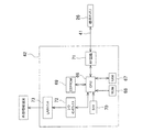
図9は、R/Wユニット42の制御機構を示したブロック図である。R/Wユニット42は、CPU(監視手段)66、RAM67、ROM68、EEPROM(記憶手段)69、タイマ70、機枠アンテナと機枠タグとの間でRFID通信を行うためのRF回路71等を有している。また、CPU66は、I/Oインタフェイス72を介して、外部の装置等へ信号を出力する際の出力ポートであるLANユニット73等とも接続されている。さらに、LANユニット73は、外部情報端末(パソコン等)と接続されている。加えて、RF回路71は、同軸ケーブル41を介して機枠アンテナ26と接続されている。なお、R/Wユニット42は、パチンコ機1が設置されている島設備から24時間(常時)電源供給されるようになっている。また、EEPROM69には、機枠タグに記憶されている識別情報と同じものが予め登録されている。
FIG. 9 is a block diagram showing a control mechanism of the R /
このように構成されたR/Wユニット42は、RF回路71を介して機枠アンテナ26と機枠タグ28との間で常時(24時間)RFID通信を行っており、機枠タグ28からの反射波を受信すると、再度呼出信号を発信するという監視動作を、短時間(約数十ms)の周期で繰り返し実行している。そして、上記のような監視動作において、例えば反射波を受信しなくなった場合等の異常な状態を検知した場合には、異常な状態と判断し、監視履歴情報として異常な状態を検知した時刻等をEEPROM69に記憶(監視履歴情報を時刻に関連づけて記憶)するようになっている。
The R /
(3)実施例の監視システム及びパチンコ機の動作内容
パチンコ機1は、メイン制御基板のLSIに記憶されたプログラムにしたがって、主たる遊技動作を実行する。そして、発射ハンドル9の回転操作によって遊技領域3に打ち出された遊技球が、各種の入賞装置に入賞した場合には、遊技球払出装置24が所定数の遊技球を賞品球として供給皿10に払い出す。また、遊技領域3に打ち出された遊技球が図柄始動口15に入賞すると、「抽選」を実行し、「大当たり」を生起させるか否かを決定する。さらに、「抽選」を実行すると略同時に、図柄表示装置13の液晶画面14に表示された図柄を変動させ(他の図柄と順々に入れ替わる動画を表示し)、所定時間後に停止させて新たな図柄を表示する。さらに、「抽選」において「大当たり」が生起した場合には、図柄の変動後に、予め設定された「大当たり図柄」を表示するとともに、「大当たり状態」を生起させて、大入賞装置16の扉部材を所定回数だけ断続的に開放させる。なお、大入賞装置16の扉部材は、「大当たり状態」生起時以外では開放しないようになっている。また、扉部材の内部の大入賞口に遊技球が入賞した場合にも、所定数の遊技球を賞品球として供給皿10に払い出す。したがって、「大当たり状態」が生起した場合には、扉部材が断続的に開成するため、遊技者は多くの賞品球を獲得することが可能となる。
(3) Monitoring system and operation contents of pachinko machine of embodiment The pachinko machine 1 executes the main game operation according to the program stored in the LSI of the main control board. When the game ball launched into the
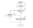
一方、パチンコ機1は、遊技枠6の不正開放等の行為を監視すべく、R/Wユニット42の制御により機枠タグ28と機枠アンテナ26との間でRFID通信を行っている。図10はパチンコ機1の監視動作を示すフローチャート図である。以下、図10にしたがって、パチンコ機1の監視動作を説明する。
S1において、R/Wユニット42のRF回路71が、機枠アンテナ26を介して機枠タグ28へと所定の周波数の呼出波を送信している。機枠タグ28は、機枠アンテナ26から送信された呼出波をRF回路44にて受信すると、直ちにEEPROM45に記憶されている識別情報を呼び出し、その識別情報を反射波にのせて送信する。R/Wユニット42は、機枠アンテナ26の送受信回路39にて機枠タグ28より送信された反射波を受信する。その際、S2において、呼出波を機枠タグ28へと送信してから所定時間内(たとえば50ms以内)に、機枠タグ28からの反射波を受信したか否かが判定(監視手段により監視)される。S2における判定の結果、所定時間内に受信したと判定された場合には、正常な状態であると判断され、S3へと進む。
On the other hand, the pachinko machine 1 performs RFID communication between the
In S <b> 1, the
S3において、R/Wユニット42では、受信した機枠タグ28からの反射波に含まれる識別情報と、予めR/Wユニット42のEEPROM69に登録されている識別情報が一致するか否か(つまり、識別情報が正しいか否か)を判定(監視手段による監視)する。判定の結果、識別情報が一致する場合には、正常な状態であると判断され、S1へと戻り、再度直ちに機枠アンテナ26を介して呼出波を送信する。
In S3, the R /
一方、S2の判定で所定時間内に反射波を受信できなかったと判定された場合及びS3の判定で受信した識別情報が登録されているものと異なっていた場合には、異常な状態であると判断される。そして、S4へと進み、異常な状態であると判断された時刻をタイマ70に基づいて監視履歴情報としてR/Wユニット42のEEPROM69に記憶し、パソコン等の外部情報端末にて異常な状態が検知された旨を報知する。その後、またS1へと戻り再度呼出波を送信する。
以上のような態様で、パチンコ機1の監視動作は行われる。
On the other hand, if it is determined in S2 that the reflected wave has not been received within the predetermined time, and if the identification information received in S3 is different from the registered information, the state is abnormal. To be judged. Then, the process proceeds to S4, and the time determined to be in an abnormal state is stored in the
The monitoring operation of the pachinko machine 1 is performed in the manner as described above.
(4)実施例の監視システム及びパチンコ機の効果
アンテナ台27は、上記の如く、上段へいくに従って徐々に小さな長方形状となる枠体29と、枠体上に設けられた接続部30、30・・とからなる階段状に形成したため、所定の段において枠体29と接続部30、30・・とを切り離すことにより容易にその高さを調節することが可能である。したがって、挿入された機枠アンテナ26と、機枠に固着されている機枠タグ28との間の距離をRFID通信可能な所定の距離に容易に調節することができる。
また、従来のように機枠アンテナ26及び機枠タグ28どちらもパチンコ機1に直接固着する構成ではRFID通信不可能な位置であっても、アンテナ台27を利用することによりRFID通信可能とし得るため、パチンコ機1の形状にとらわれることなく任意の位置に機枠タグ28や機枠アンテナ26を設置することができる。つまり、従来より遊技場ホール等で使用されている様々なタイプのパチンコ機に設置可能である。
(4) Effect of Monitoring System and Pachinko Machine of Example As described above, the
Further, even if the
さらに、アンテナ台27は合成樹脂製であるため、ニッパ等の切断工具を用いれば容易に切断することができる。また、機枠タグ28と機枠アンテナ26との間におけるRFID通信を妨害することもない。加えて、アンテナ台27は枠体29を当接させた状態で設置されるため、非常に安定性がよい。
さらにまた、アンテナ台27は、機枠アンテナ26を挿入部31に容易に挿入可能に構成されている上、機枠アンテナ26に取り付けられる同軸ケーブル41を窓部37から外へと導くようにしている。加えて、係止片33に設けられた係止爪32により、機枠アンテナ26の挿入部31からの不用意な抜け止めを防止している。したがって、アンテナ台27を設置している際等に機枠アンテナ26が抜け落ちることはなく、非常に作業性に優れたものとなっている。
Furthermore, since the
Furthermore, the
一方、パチンコ機1は、R/Wユニット42の制御により、機枠アンテナ26を介して機枠タグ28との間で上述したようなRFID通信を行っている。もし、遊技枠6が不正に開放された場合には、機枠タグ28からの反射波を所定時間内に受信できなくなるため、R/Wユニット42は異常な状態であると判断し、反射波を受信できなくなった時刻をEEPROM69に記憶する。したがって、不正行為が行われている事態を直ちに(リアルタイム)で検知することが可能であるため、遊技枠の不正開放を早期発見することができ、さらには、パチンコ機1に対する不正行為の防止へとつながることにもなる。
On the other hand, the pachinko machine 1 performs RFID communication as described above with the
また、機枠タグ28からの反射波に含まれる識別情報が、R/Wユニット42に予め登録されているものと異なっている場合にも、R/Wユニット42は異常であると判断し、その反射波を受信した時刻をEEPROM69に記憶する。したがって、機枠タグ28やR/Wユニット42の不正交換といった事態にも効果的に対応することが可能である。
さらに、R/Wユニット42は島設備より常時電源供給を受けているため、たとえパチンコ機1の電源が落とされている夜間等であったとしても、不正行為を検知することができる。
Further, when the identification information included in the reflected wave from the
Furthermore, since the R /
加えて、R/Wユニット42、機枠アンテナ26、アンテナ台27及び機枠タグ28は、従来より遊技場ホール等にて使用されているパチンコ機1に搭載可能であり、また搭載するだけで監視を行うことができる構成となっているため、該監視システムを備えた遊技機の生産性を非常に高めることができる。
In addition, the R /
(5)本発明の変更例の説明
本発明の監視システム及び遊技機は、上記実施形態の態様に何ら限定されるものではなく、メイン制御基板、メイン基板収納ケース、監視制御装置、ICタグ、アンテナ、アンテナ台の材料、形状、構造等の構成を本発明の趣旨を逸脱しない範囲内で適宜変更することができる。
(5) Description of Modifications of the Present Invention The monitoring system and gaming machine of the present invention are not limited to the aspects of the above-described embodiment, and the main control board, the main board storage case, the monitoring control device, the IC tag, The configuration of the antenna, antenna base material, shape, structure, and the like can be changed as appropriate without departing from the spirit of the present invention.
たとえば、上記実施形態では、ICタグとアンテナとにより機枠に対する遊技枠の開閉状態を監視する構成としたがそれに限定されることはなく、例えばメイン基板収納ケースを前ケースと後ケースとからなる分割式のメイン基板収納ケースとし、該メイン基板収納ケースをタグとアンテナとにより監視するようにしてもよい。また、遊技枠に対する前面枠の開閉状態を監視するものとしてもよいし、大入賞装置における扉部材の開閉状態、貯留皿や供給皿等の開閉状態を監視するものとしても何ら問題はない。大入賞装置の扉部材の開閉状態を監視するようにすることで、ピアノ線等を用いて遊技中に不正に扉部材を開放させるような不正行為を瞬時に発見することができ、不正を未然に防止することができるようになる。さらに、遊技機において一箇所のみを監視するものとしてもよいし、複数箇所で監視を行うようにすることは当然可能である。
また、複数箇所において監視を行う構成としたとしても、その複数箇所における監視を一つのR/Wユニットで制御可能に構成することは当然可能である。
For example, in the above embodiment, the IC frame and the antenna are used to monitor the open / closed state of the game frame with respect to the machine frame, but the present invention is not limited thereto. For example, the main board storage case includes a front case and a rear case. A split-type main board storage case may be used, and the main board storage case may be monitored by a tag and an antenna. Moreover, it is good also as what monitors the opening / closing state of the front frame with respect to a game frame, and there is no problem as what monitors the opening / closing state of the door member in an extra prize apparatus, and the opening / closing states of a storage tray, a supply tray, etc. By monitoring the open / closed state of the door member of the grand prize winning device, it is possible to instantly detect fraudulent acts that open the door member illegally during a game using a piano wire, etc. Will be able to prevent. Furthermore, only one location may be monitored in the gaming machine, and it is naturally possible to monitor at a plurality of locations.
Moreover, even if it is set as the structure which monitors in several places, it is naturally possible to comprise so that the monitoring in the several places can be controlled by one R / W unit.
さらに、メイン基板収納ケースを分割式のものとする場合には、シンプルな係合機構(たとえば先端が矢尻状に形成された係止片と係合孔とによる機構)のみを設けたものに限定されず、片方のケースの端縁に、ワンウェイタイプのネジを保持した切断可能な複数のネジ保持部を設ける(たとえば、小径の連結体を介して片方のケースの本体にネジ保持部が繋がった形状となるように、片方のケース、連結体、ネジ保持部を合成樹脂によって一体的に成形する)とともに、他方のケースの端縁に、ネジ保持部に保持されたネジを螺着させるネジ孔を形成したもの等に変更することも可能である。かかる構成を採用した場合には、メイン基板収納ケースが不正に開放されると、メイン基板収納ケースに不正に開放された痕跡が残り、目視によってもその事態を速やかに把握することができるため、メイン基板収納ケースの不正開放が一層困難なものとなる、というメリットがある。 Furthermore, when the main board storage case is of a split type, it is limited to a simple engagement mechanism (for example, a mechanism with a locking piece and an engagement hole whose tip is formed in an arrowhead shape). Instead, a plurality of severable screw holders holding one-way type screws are provided at the edge of one case (for example, the screw holder is connected to the main body of one case via a small-diameter coupling body). The case, connecting body, and screw holding part are integrally formed of synthetic resin so as to have a shape), and the screw hole to which the screw held by the screw holding part is screwed to the edge of the other case It is also possible to change to those formed. When such a configuration is adopted, if the main board storage case is illegally opened, the trace that has been illegally opened remains in the main board storage case, so that the situation can be quickly grasped visually, There is an advantage that unauthorized opening of the main board storage case becomes more difficult.
さらにまた、上記実施形態では、機枠に対する遊技枠の開閉状態を監視するために、機枠の上面裏側にICタグを、遊技枠の遊技球タンクの隣にアンテナ台及びアンテナを設置するものとしたが、ICタグ及びアンテナ等の設置位置はそれに限定されることはない。たとえば、遊技枠の開放側端面の側面にアンテナ台及びアンテナを、機枠の開放側端面内側にタグをそれぞれ設置したとしても何ら問題はない。
加えて、実施形態では、アンテナ台にアンテナを挿入する構成としたが、ICタグをアンテナ台のようなICタグ台に挿入してアンテナとタグとの距離を調節するようにしてもよいし、両者を台にそれぞれ挿入して調節するように構成したとしても何ら問題はない。
Furthermore, in the above embodiment, in order to monitor the open / closed state of the game frame relative to the machine frame, an IC tag is installed on the back side of the upper surface of the machine frame, and an antenna stand and an antenna are installed next to the game ball tank of the game frame. However, the installation positions of the IC tag and the antenna are not limited thereto. For example, there is no problem even if an antenna stand and an antenna are installed on the side of the open side end face of the game frame, and a tag is installed on the inside of the open side end face of the machine frame.
In addition, in the embodiment, the antenna is inserted into the antenna base, but the IC tag may be inserted into an IC tag base such as an antenna base to adjust the distance between the antenna and the tag. There is no problem even if both are inserted into the base and adjusted.
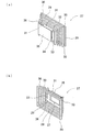
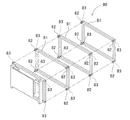
また、アンテナ台の形状及び構成も、実施形態のものに限定されることは当然ない。たとえば、実施形態では階段状に一体形成されたものとしているが、図11に示されているようなものとすることもできる。図11に示されているアンテナ台80は、階段状のように上段へいくに従って徐々に枠体81が小さくなることはなく、同じ大きさの枠体81が積み重ねられたものである。また、一体形成されておらず、枠体81の上面に接続部82、82・・が突設されたものを一つのユニットとしており、一方のユニットの各接続部82を他方のユニットの枠体81に形成された各凹部83に嵌合させて組み立てるようになっている。このような組み立て式のアンテナ台とすることにより、高さ調節の際に切断工具を利用する必要はなく、より作業性の高いものとすることができる。勿論、階段状のアンテナ台をユニットを用いた組み立て式のものとすることは当然可能である。
Also, the shape and configuration of the antenna stand are not limited to those of the embodiment. For example, in the embodiment, it is integrally formed in a staircase shape, but it may be as shown in FIG. In the antenna stand 80 shown in FIG. 11, the
他にも、アンテナ台を、下面が粘着性を有したシールを複数枚貼り合わせることによって形成し、任意の枚数のシールをはがすことで高さを調節するようなものとしてもよいし、枠体を長方形状でなく円形のものとしても何ら問題はない。
加えて、実施形態では一段の高さを4mmとしたが、一段の高さは4mmに限定されることはなく、5mm以上でもよいし、3mm以下でも何ら問題はない。さらに、上段へいくに従って接続部の長さを徐々に長くすることにより、一段の高さを徐々に高くする(例えば、最下段では2mmであるのが、最上段では8mmとなっている等)ことも可能であるし、逆に上段へいくに従って一段の高さを徐々に低くしてもよい。さらにまた、上述したような組み立て式のものにおいて、接続部の長さの異なるユニットを組み合わせることにより、より微調整可能なアンテナ台とすることもできる。
In addition, the antenna base may be formed by pasting together a plurality of stickers whose bottom surface is adhesive, and the height may be adjusted by removing any number of stickers. There is no problem even if the shape is not rectangular but circular.
In addition, although the height of one step is 4 mm in the embodiment, the height of one step is not limited to 4 mm, and may be 5 mm or more, and there is no problem even if it is 3 mm or less. Furthermore, by gradually increasing the length of the connecting portion as it goes to the upper stage, the height of one stage is gradually increased (for example, 2 mm at the lowermost stage is 8 mm at the uppermost stage). It is also possible, and conversely, the height of one stage may be gradually lowered as it goes up. Furthermore, in the assembly type as described above, an antenna base that can be finely adjusted can be obtained by combining units having different connection lengths.
また、監視動作に利用するICタグやアンテナを遊技枠及び機枠等に固着する方法は、接着剤による接着であってもよいし、ICタグやアンテナを構成する樹脂を遊技枠や機枠に融着させる方法や、ICタグやアンテナを遊技枠や機枠に一体的に成形する方法等の別の取付方法に変更することも可能である。なお、シート状のICタグやアンテナを、裏面に粘着剤を塗布したシールとするとともに、粘着剤層の表面に剥離紙を貼着しておき、設置する際に剥離紙を剥離して貼着するようにすれば、ICタグやアンテナの設置が非常に容易になる、というメリットがある。 In addition, the method of adhering the IC tag or antenna used for the monitoring operation to the game frame or the machine frame may be adhesive bonding, or the resin constituting the IC tag or antenna is attached to the game frame or the machine frame. It is also possible to change to another attachment method such as a method of fusing, an IC tag or an antenna formed integrally with a game frame or a machine frame. In addition, a sheet-like IC tag or antenna is used as a seal with an adhesive applied to the back, and a release paper is attached to the surface of the adhesive layer, and the release paper is peeled off when installed. By doing so, there is a merit that the installation of the IC tag and the antenna becomes very easy.
さらに、上述したような、ICタグ及びアンテナをシールとする場合には、それらが剥離された場合に機能を果たさなくなるようにする(いわゆる、自己破壊タイプのものとする)ことも可能である。そのように構成した場合には、遊技機が奏する遊技枠や前面枠等の不正開放防止機能をより精度の高いものとすることが可能となる。なお、タグやアンテナを自己破壊タイプのものとする方法としては、タグやアンテナをフレキシブルプリント基板により形成したものとし、該基板の表面に積層する粘着剤層中に送受信回路を形成する方法や、剥離によって所定量以上の応力が加わると短絡するような回路をタグやアンテナに設ける(内蔵させる)方法等を採用することができる。 Furthermore, when the IC tag and the antenna as described above are used as a seal, it is possible to prevent the function from being performed when they are peeled off (so-called self-destructive type). In such a configuration, it is possible to make the unauthorized opening prevention function such as a game frame and a front frame played by the gaming machine more accurate. As a method of making the tag and the antenna of the self-destruct type, the tag and the antenna are formed of a flexible printed circuit board, a method of forming a transmission / reception circuit in an adhesive layer laminated on the surface of the circuit board, For example, a method of providing (incorporating) a circuit in the tag or the antenna that is short-circuited when a predetermined amount of stress is applied due to peeling can be employed.
さらにまた、ICタグは、他のICタグと識別するためのIDコードのみならずメーカーIDやホールID等の識別情報をも記憶させたものに変更することも可能である。さらに、ICタグは、RFID通信を利用して識別情報を送信するものに限定されず、赤外線通信を利用して識別情報を送信するもの等に変更することも可能である。さらに、本発明の遊技機は、パチンコ機に限定されず、スロットマシーンやテレビゲーム等のパチンコ機以外の遊技機に変更することも可能である。 Furthermore, the IC tag can be changed to one that stores not only an ID code for identifying another IC tag but also identification information such as a manufacturer ID and a hall ID. Further, the IC tag is not limited to the one that transmits identification information using RFID communication, but can be changed to one that transmits identification information using infrared communication. Furthermore, the gaming machine of the present invention is not limited to a pachinko machine, but can be changed to a gaming machine other than a pachinko machine such as a slot machine or a video game.
加えて、上記実施形態では、監視履歴情報を、可動部におけるRFID通信が不可となった時刻に関連づけたものとしているが、RFID通信が正常に行われるようになった時刻やRFID通信が異常であった時間等に関連づけたものとしてもよい。そうすることで、たとえ不正行為が行われた後に正常な状態に復帰した場合等に、より詳しい監視履歴情報を得ることができる。さらに、後に監視履歴情報を参照した場合に、所定時間内に反射波を受信できなかったのか或いは受信した識別情報が異なっていたのかを区別することができるような監視履歴情報とすることも可能である。 In addition, in the above embodiment, the monitoring history information is associated with the time when RFID communication in the movable part is disabled. However, the time when RFID communication is normally performed or the RFID communication is abnormal. It may be associated with a certain time. By doing so, more detailed monitoring history information can be obtained, for example, when a normal state is restored after an illegal act is performed. Furthermore, when referring to the monitoring history information later, it is possible to set the monitoring history information so that it is possible to distinguish whether the reflected wave is not received within a predetermined time or whether the received identification information is different. It is.
また、R/Wユニットは、テンキー等の入力手段が設けられており、所定の入力をすることによって、R/WユニットのEEPROMに記憶されている識別情報を、タグの交換等に伴い適宜書換変更可能な構成にしてもよい。なお、R/Wユニットを、上記実施形態の如く、ごく短期間の周期で定期的な監視を行うものとした場合には、不正行為が行われた事態をリアルタイムで把握することができる、というメリットがある。また、R/Wユニットは、異常を検知した旨を不揮発性の記憶手段であるEEPROMに記憶するものに限定されず、通常のROM、RAM、ハードディスク、光メディア等の記憶手段に記憶するもの等でもよい。さらに、R/Wユニットは、パチンコ機が設置される島設備から電源供給を受けるものに限定されず、パチンコ機から直接電源供給を受けるもの等でもよい。加えて、R/Wユニットはパチンコ機とは別体のものであり、パチンコ機に設置される必要性はなく、パチンコ機の外部に設置してもよい。 Also, the R / W unit is provided with input means such as a numeric keypad, and by performing predetermined input, the identification information stored in the EEPROM of the R / W unit is appropriately rewritten as the tag is replaced. A changeable configuration may be used. In addition, when the R / W unit is to perform periodic monitoring in a very short period as in the above embodiment, it is possible to grasp in real time the situation in which fraudulent activity has been performed. There are benefits. In addition, the R / W unit is not limited to storing the fact that an abnormality has been detected in the EEPROM, which is a non-volatile storage means, but is stored in a storage means such as a normal ROM, RAM, hard disk, optical media, etc. But you can. Furthermore, the R / W unit is not limited to the unit that receives power supply from the island facility where the pachinko machine is installed, and may be one that receives power supply directly from the pachinko machine. In addition, the R / W unit is separate from the pachinko machine and does not need to be installed in the pachinko machine, and may be installed outside the pachinko machine.
さらに、R/Wユニットは、営業時間中には異常事態の報知のみを行い、パチンコ機が稼働していない夜間等に監視履歴情報をEEPROM等の記憶手段に記憶のみ行うものに変更することも可能である。なお、外部情報端末では、必要に応じて、監視履歴情報を参照したり、別の記憶手段に保存したりすることは当然可能である。その際のR/Wユニットと外部のネットワークとの接続方法は、有線による接続であってもよいし、無線による接続でもよい。さらにまた、正常でない事態を報知する場合には、図柄表示装置等に不正行為が行われている可能性がある旨を表示するようにしてもよいし、不正表示ランプ等を別途設け、点灯点滅させるようにしてもよい。加えて、不正行為をなされた可能性がある場合には、効果音により周囲に報知するようにしてもよい。 Furthermore, the R / W unit may only change to a unit that only reports an abnormal situation during business hours and only stores monitoring history information in a storage means such as an EEPROM at night when the pachinko machine is not operating. Is possible. In the external information terminal, it is naturally possible to refer to the monitoring history information or save it in another storage unit as necessary. The connection method between the R / W unit and the external network at that time may be a wired connection or a wireless connection. Furthermore, when notifying an abnormal situation, it may be displayed on the symbol display device or the like that there is a possibility that fraud is being carried out, or a fraudulent display lamp or the like is separately provided and lit and flashing. You may make it make it. In addition, if there is a possibility that an illegal act has been made, it may be notified to the surroundings by a sound effect.
1・・パチンコ機、5・・機枠、6・・遊技枠、26・・機枠アンテナ、27・・アンテナ台、28・・機枠タグ、29・・枠体、30・・接続部、31・・挿入部、32・・係止爪、33・・係止片、42・・R/Wユニット、66・・CPU、69・・EEPROM、70・・タイマ、71・・RF回路。 1 .. Pachinko machine, 5 .. Machine frame, 6 .. Game frame, 26 .. Machine frame antenna, 27 .. Antenna stand, 28 .. Machine frame tag, 29 .. Frame body, 30. 31 .. Insertion section, 32.. Locking claw, 33.. Locking piece, 42 ... R / W unit, 66 ... CPU, 69 ... EEPROM, 70 ... Timer, 71 ... RF circuit.
Claims (4)
前記第一の部材あるいは第二の部材のどちらか一方の部材に設けられる呼出波を受信すると記憶している固有の識別情報を含む反射波を出力するICタグと、
他方の部材に設けられ、前記ICタグに対して呼出波を送信し、前記ICタグからの反射波を受信するアンテナと、
前記ICタグとアンテナとの間における非接触通信により前記可動部の監視を行う監視手段と、前記ICタグに記憶されている固有の識別情報及び監視手段による監視結果を含む監視履歴情報を記憶する記憶手段とを備えた監視制御装置と、
からなる監視システムであって、
前記ICタグ或いは前記アンテナの少なくとも一方を、枠体と各枠体間を接続する接続部とからなる分断部が多段に積み重ねられた補助具に設置しており、該補助具から任意の数の分断部を分断させることにより、前記ICタグと前記アンテナとの間の距離を調節可能としたことを特徴とする監視システム。 Used in a gaming machine having at least one set of movable parts composed of a first member and a second member, the relative distance of which varies with at least one movement;
An IC tag that outputs a reflected wave including unique identification information stored when receiving a ringing wave provided on either the first member or the second member;
An antenna provided on the other member for transmitting a ringing wave to the IC tag and receiving a reflected wave from the IC tag;
Monitoring means for monitoring the movable part by non-contact communication between the IC tag and the antenna, and monitoring history information including unique identification information stored in the IC tag and a monitoring result by the monitoring means are stored. A monitoring control device comprising storage means;
A monitoring system comprising:
At least one of the IC tag or the antenna is installed in an auxiliary tool in which divided parts composed of a frame body and a connection part that connects each frame body are stacked in multiple stages . A monitoring system characterized in that the distance between the IC tag and the antenna can be adjusted by dividing the dividing portion.
前記監視手段において、前記アンテナを介して呼出波を送信してから所定時間内に前記ICタグからの反射波を受信し、且つ受信した反射波に含まれる識別情報が前記記憶手段に予め記憶されているもの識別情報と一致した場合のみを正常と判断し、それ以外の場合を異常と判断し、異常と判断した場合には前記監視履歴情報を異常と判断した時刻に関連づけて記憶することを特徴とする請求項1〜3のいずれかに記載の監視システム。 The monitoring control device includes a timer,
In the monitoring means, the reflected wave from the IC tag is received within a predetermined time after transmitting the calling wave via the antenna, and the identification information included in the received reflected wave is stored in the storage means in advance. Only when it matches the identification information that is present, it is determined as normal, otherwise it is determined as abnormal, and when it is determined as abnormal, the monitoring history information is stored in association with the time when it is determined as abnormal. The monitoring system according to any one of claims 1 to 3.
Priority Applications (1)
| Application Number | Priority Date | Filing Date | Title |
|---|---|---|---|
| JP2003376200A JP4474635B2 (en) | 2003-11-05 | 2003-11-05 | Monitoring system |
Applications Claiming Priority (1)
| Application Number | Priority Date | Filing Date | Title |
|---|---|---|---|
| JP2003376200A JP4474635B2 (en) | 2003-11-05 | 2003-11-05 | Monitoring system |
Publications (2)
| Publication Number | Publication Date |
|---|---|
| JP2005137518A JP2005137518A (en) | 2005-06-02 |
| JP4474635B2 true JP4474635B2 (en) | 2010-06-09 |
Family
ID=34687343
Family Applications (1)
| Application Number | Title | Priority Date | Filing Date |
|---|---|---|---|
| JP2003376200A Expired - Fee Related JP4474635B2 (en) | 2003-11-05 | 2003-11-05 | Monitoring system |
Country Status (1)
| Country | Link |
|---|---|
| JP (1) | JP4474635B2 (en) |
Families Citing this family (1)
| Publication number | Priority date | Publication date | Assignee | Title |
|---|---|---|---|---|
| JP2007190223A (en) * | 2006-01-19 | 2007-08-02 | Samii Kk | Pachinko game machine |
Family Cites Families (8)
| Publication number | Priority date | Publication date | Assignee | Title |
|---|---|---|---|---|
| JP2524565Y2 (en) * | 1989-08-31 | 1997-02-05 | ダイコク電機株式会社 | Monitoring equipment for pachinko game machines |
| JPH0650454U (en) * | 1992-12-16 | 1994-07-12 | 眞秀 坂本 | Animal toilet bowl |
| JPH08227441A (en) * | 1995-02-21 | 1996-09-03 | Sumitomo Electric Ind Ltd | Card reader |
| JPH09165971A (en) * | 1995-12-14 | 1997-06-24 | Tokyo Gas Co Ltd | Adjusting device for housing components |
| JPH09195482A (en) * | 1996-01-23 | 1997-07-29 | Hinaka Seisakusho:Kk | Step difference dissolving member for indoor |
| JP3465869B2 (en) * | 1997-04-11 | 2003-11-10 | ニッタン株式会社 | Anomaly detection device and anomaly monitoring system |
| JP3058967U (en) * | 1998-11-09 | 1999-06-22 | 株式会社サンワ福岡 | Sponge pillow |
| JP3094068U (en) * | 2002-11-14 | 2003-05-30 | ホクメイ株式会社 | Step platform for barrier-free |
-
2003
- 2003-11-05 JP JP2003376200A patent/JP4474635B2/en not_active Expired - Fee Related
Also Published As
| Publication number | Publication date |
|---|---|
| JP2005137518A (en) | 2005-06-02 |
Similar Documents
| Publication | Publication Date | Title |
|---|---|---|
| JP7629214B2 (en) | Gaming Machines | |
| JP7477899B2 (en) | Gaming Machines | |
| JP7629217B2 (en) | Gaming Machines | |
| JP7515192B2 (en) | Gaming Machines | |
| JP2024024735A (en) | gaming machine | |
| JP2024024751A (en) | gaming machine | |
| JP2024024752A (en) | gaming machine | |
| JP2024024736A (en) | gaming machine | |
| JP4395708B2 (en) | Game machine | |
| JP4474635B2 (en) | Monitoring system | |
| JP2023142544A (en) | Game machine | |
| JP7566349B2 (en) | Gaming Machines | |
| JP2005103141A (en) | Game machine | |
| JP4431740B2 (en) | Gaming machine monitoring system and gaming machine | |
| JP2024024743A (en) | gaming machine | |
| JP2024024756A (en) | gaming machine | |
| JP2024024742A (en) | gaming machine | |
| JP4151968B2 (en) | Monitoring system for gaming machines | |
| JP4203623B2 (en) | Gaming machine management system and gaming machine | |
| JP2005245870A (en) | Game machine monitoring system | |
| JP7629221B2 (en) | Gaming Machines | |
| JP7629216B2 (en) | Gaming Machines | |
| JP7629220B2 (en) | Gaming Machines | |
| JP7593664B2 (en) | Gaming Machines | |
| JP7492279B2 (en) | Gaming Machines |
Legal Events
| Date | Code | Title | Description |
|---|---|---|---|
| A621 | Written request for application examination |
Free format text: JAPANESE INTERMEDIATE CODE: A621 Effective date: 20061102 |
|
| A977 | Report on retrieval |
Free format text: JAPANESE INTERMEDIATE CODE: A971007 Effective date: 20091028 |
|
| A131 | Notification of reasons for refusal |
Free format text: JAPANESE INTERMEDIATE CODE: A131 Effective date: 20091104 |
|
| A521 | Written amendment |
Free format text: JAPANESE INTERMEDIATE CODE: A523 Effective date: 20091225 |
|
| TRDD | Decision of grant or rejection written | ||
| A01 | Written decision to grant a patent or to grant a registration (utility model) |
Free format text: JAPANESE INTERMEDIATE CODE: A01 Effective date: 20100126 |
|
| A01 | Written decision to grant a patent or to grant a registration (utility model) |
Free format text: JAPANESE INTERMEDIATE CODE: A01 |
|
| A61 | First payment of annual fees (during grant procedure) |
Free format text: JAPANESE INTERMEDIATE CODE: A61 Effective date: 20100225 |
|
| R150 | Certificate of patent or registration of utility model |
Ref document number: 4474635 Country of ref document: JP Free format text: JAPANESE INTERMEDIATE CODE: R150 Free format text: JAPANESE INTERMEDIATE CODE: R150 |
|
| FPAY | Renewal fee payment (event date is renewal date of database) |
Free format text: PAYMENT UNTIL: 20130319 Year of fee payment: 3 |
|
| FPAY | Renewal fee payment (event date is renewal date of database) |
Free format text: PAYMENT UNTIL: 20130319 Year of fee payment: 3 |
|
| FPAY | Renewal fee payment (event date is renewal date of database) |
Free format text: PAYMENT UNTIL: 20130319 Year of fee payment: 3 |
|
| FPAY | Renewal fee payment (event date is renewal date of database) |
Free format text: PAYMENT UNTIL: 20130319 Year of fee payment: 3 |
|
| FPAY | Renewal fee payment (event date is renewal date of database) |
Free format text: PAYMENT UNTIL: 20160319 Year of fee payment: 6 |
|
| R250 | Receipt of annual fees |
Free format text: JAPANESE INTERMEDIATE CODE: R250 |
|
| R250 | Receipt of annual fees |
Free format text: JAPANESE INTERMEDIATE CODE: R250 |
|
| LAPS | Cancellation because of no payment of annual fees |