JP4472983B2 - Boxing equipment - Google Patents
Boxing equipment Download PDFInfo
- Publication number
- JP4472983B2 JP4472983B2 JP2003436897A JP2003436897A JP4472983B2 JP 4472983 B2 JP4472983 B2 JP 4472983B2 JP 2003436897 A JP2003436897 A JP 2003436897A JP 2003436897 A JP2003436897 A JP 2003436897A JP 4472983 B2 JP4472983 B2 JP 4472983B2
- Authority
- JP
- Japan
- Prior art keywords
- box
- unit
- sheet
- opening
- making
- Prior art date
- Legal status (The legal status is an assumption and is not a legal conclusion. Google has not performed a legal analysis and makes no representation as to the accuracy of the status listed.)
- Expired - Fee Related
Links
- 238000003780 insertion Methods 0.000 claims description 20
- 230000037431 insertion Effects 0.000 claims description 20
- 238000004806 packaging method and process Methods 0.000 claims description 15
- 230000032258 transport Effects 0.000 claims description 15
- 238000001125 extrusion Methods 0.000 claims description 3
- 230000033001 locomotion Effects 0.000 description 32
- 238000009434 installation Methods 0.000 description 21
- 230000036544 posture Effects 0.000 description 18
- 238000012546 transfer Methods 0.000 description 15
- 230000007246 mechanism Effects 0.000 description 14
- 238000012856 packing Methods 0.000 description 11
- 210000000078 claw Anatomy 0.000 description 10
- 239000012530 fluid Substances 0.000 description 10
- 230000009191 jumping Effects 0.000 description 8
- 239000000725 suspension Substances 0.000 description 5
- 238000003825 pressing Methods 0.000 description 4
- 230000008859 change Effects 0.000 description 3
- 238000010586 diagram Methods 0.000 description 3
- 230000000694 effects Effects 0.000 description 3
- 230000001965 increasing effect Effects 0.000 description 3
- 238000002360 preparation method Methods 0.000 description 3
- 238000011144 upstream manufacturing Methods 0.000 description 3
- 230000005540 biological transmission Effects 0.000 description 2
- 230000003028 elevating effect Effects 0.000 description 2
- 235000011194 food seasoning agent Nutrition 0.000 description 2
- 230000006872 improvement Effects 0.000 description 2
- 238000007689 inspection Methods 0.000 description 2
- 238000012545 processing Methods 0.000 description 2
- 238000001179 sorption measurement Methods 0.000 description 2
- 238000004804 winding Methods 0.000 description 2
- 230000009471 action Effects 0.000 description 1
- 238000013459 approach Methods 0.000 description 1
- 230000003111 delayed effect Effects 0.000 description 1
- 238000001514 detection method Methods 0.000 description 1
- 238000006073 displacement reaction Methods 0.000 description 1
- 238000009826 distribution Methods 0.000 description 1
- 238000000605 extraction Methods 0.000 description 1
- 238000007726 management method Methods 0.000 description 1
- 238000002156 mixing Methods 0.000 description 1
- 238000005192 partition Methods 0.000 description 1
- 230000002093 peripheral effect Effects 0.000 description 1
- 235000011888 snacks Nutrition 0.000 description 1
- 238000003860 storage Methods 0.000 description 1
- 230000007723 transport mechanism Effects 0.000 description 1
- 238000005303 weighing Methods 0.000 description 1
Images


Landscapes
- Container Filling Or Packaging Operations (AREA)
- Supplying Of Containers To The Packaging Station (AREA)
Description
本発明は袋入商品や箱入商品等の物品の箱詰装置、特に、物品を多段詰めする箱詰装置に関し、物品の包装及び流通の技術分野に属する。なお、本明細書では、箱を立てたとき、すなわち開口を上を向けたときの上下方向の並びを「層」といい、水平方向の並びを「段」又は「列」という。 The present invention relates to a packaging device for articles such as bags and goods, and more particularly to a packaging apparatus for multi-packing articles, and belongs to the technical field of packaging and distribution of articles. In this specification, when the box is erected, that is, when the opening is directed upward, the vertical arrangement is referred to as “layer”, and the horizontal arrangement is referred to as “stage” or “column”.
従来、工場等において製造された製品を卸売商や小売店に出荷するときに、段ボール等の箱に所定の数量ずつ製品を箱詰めすることが行われている。この箱詰め作業は手作業で行われることが多いが、これを自動化するような箱詰めシステムが種々提案されている。ところで、このような箱詰装置では、段ボール等の製函用シートを箱状に組み立てることが必要である。特許文献1の箱詰装置では、段ボール等の製函用シートを自動的に箱状に組み立てる製函装置が、箱詰装置とは別の場所に設定されている。そして、作業者が、製函機で組み立てられた段ボール箱を箱詰装置まで運搬し、箱詰装置上部にある箱載置台にセットするようになっている。また、特許文献2の箱詰装置では、製函部が箱詰装置の側面に付帯されており、製函部で組み立てられた段ボール箱が箱詰装置に自動的に供給されるようになっている。 Conventionally, when a product manufactured in a factory or the like is shipped to a wholesaler or a retail store, a predetermined number of products are packed in a box such as a cardboard box. This boxing operation is often performed manually, and various boxing systems that automate this have been proposed. By the way, in such a boxing device, it is necessary to assemble a box-making sheet such as cardboard in a box shape. In the boxing device of
しかし、特許文献1の箱詰装置では、製函装置が箱詰装置とは別の場所に設置されているので、設置スペースが大きくなってしまう。また、製函装置で組み立てられた段ボール等の箱を作業者が箱詰装置まで運搬しなければならず、作業者の負担が大きい。 However, in the boxing device of
また、特許文献2の箱詰装置では、箱詰装置の側面に製函部が付帯されているため、設置スペースの問題は解消されていない。 Moreover, in the boxing apparatus of
本発明は、箱詰装置に製函部を付帯させた場合でも、設置スペースが大きくならず、工場等の限られたスペースを有効に活用できる箱詰装置を提案することを課題とする。 An object of the present invention is to propose a boxing device that can effectively use a limited space in a factory or the like without increasing the installation space even when a box making unit is attached to the boxing device.
本願の請求項1に記載の発明は、折り畳まれた製函用シートを水平方向に水平状態で搬送する水平搬送部と、前記水平搬送部により搬送された前記製函用シートを箱状に組み立てる製函部と、前記製函部で組み立てられた箱を、その開口部を横方向として下方へ搬送する下方搬送部と、前記下方搬送部により搬送される前記箱に物品を横方向から挿入する挿入部とを備えていると共に、前記製函部は、前記製函用シートの開口部に挿入され、互いに離反することで箱を開口状態に保持する複数のシート開口部材を備えており、該シート開口部材は、離反時に、箱の開口部周囲で立っているフラップを外側へ折り込むフラップ折込部を有していることを特徴とする箱詰装置である。
The invention according to
本願の請求項2に記載の発明は、前記シート開口部材は、箱を開口状態に保持したまま箱を下方へ搬送するように構成されていることを特徴とする請求項1に記載の箱詰装置である。
The invention according to
本願の請求項3に記載の発明は、前記挿入部により物品が挿入された箱を下流へ排出する排出部をさらに備え、前記排出部の上方に前記水平搬送部、前記製函部、前記下方搬送部、前記挿入部が配置されていることを特徴とする請求項1または2に記載の箱詰装置である。
The invention according to claim 3 of the present application further includes a discharge unit that discharges the box in which the article is inserted by the insertion unit to the downstream, and the horizontal conveyance unit, the box making unit, and the lower part are disposed above the discharge unit. conveying unit, a boxing device according to
本願の請求項4に記載の発明は、前記排出部は、横方向を向いていた開口部が上方向を向くように箱を回転させる回転部材を備えていることを特徴とする請求項3に記載の箱詰装置である。 The invention described in claim 4 of the present application, the discharge portion, in claim 3 an opening which was facing the lateral direction, characterized in that it comprises a rotary member for rotating the box to face upward The boxing device described.
本願の請求項5に記載の発明は、前記排出部は、箱の回転時に箱を保持する保持部材と、回転後に箱を下流へ押し出す押出部材とをさらに有していることを特徴とする請求項4に記載の箱詰装置である。 The invention described in claim 5 of the present application, the discharge unit, wherein, wherein a support member for supporting a box during rotation of the box, that it further comprises a pushing member for pushing the boxes downstream after rotation Item 5. The boxing device according to Item 4 .
本願の請求項6に記載の発明は、前記排出部の下流は、前記水平搬送部の直下で平行に配置された排出搬送部であることを特徴とする請求項4または5に記載の箱詰装置である。 The invention described in claim 6 of the present application, the downstream of the discharge portion, boxing according to claim 4 or 5, wherein said a discharge conveying section arranged parallel to just below the horizontal conveying section Device.
本願の請求項1に記載の発明によれば箱詰装置の上方で製函用シートを搬送し、かつ、箱詰装置の直上方で製函を行うようにしたこと、すなわち、箱詰装置と製函部とを立体的に配置したので、設置スペースを大幅に抑制することができる。 According to the invention described in
換言すれば、箱詰装置の上方に製函部を付帯させたので、横方向(幅方向)の設置スペースが大きくならず、工場等の限られたスペースが十分に有効活用される。 In other words, since the box making unit is attached above the boxing device, the installation space in the lateral direction (width direction) does not increase, and a limited space in a factory or the like is sufficiently effectively used.
しかも、折り畳まれた製函用シートを水平状態で搬送するので、箱詰装置の高さ方向の設置スペースも抑えることができる。また、製函用シートを垂直状態で搬送する場合よりも、シートを安定して搬送することができる。 Moreover, since the folded box-making sheet is conveyed in a horizontal state, the installation space in the height direction of the boxing device can also be suppressed. Further, the sheet can be conveyed more stably than when the box-making sheet is conveyed in a vertical state.
さらに、装置に対して箱の開口部を横方向とし、物品を箱に横方向から挿入するから、箱の上部を開口部として上方から物品を挿入する場合に比べて、高さ方向の設置スペースを抑えることができる。また、横方向からの挿入とすることで、物品の整列状態を良好に保持しながら箱に物品を挿入することができる。 Further, since the opening of the box is set in the horizontal direction with respect to the apparatus and the article is inserted into the box from the horizontal direction, the installation space in the height direction is compared with the case where the article is inserted from above with the upper part of the box as the opening. Can be suppressed. Further, by inserting from the lateral direction, it is possible to insert the article into the box while keeping the alignment state of the articles satisfactorily.
また、前記製函部は、複数のシート開口部材を前記製函用シートの開口部に挿入し、互いに離反させることによって、箱を開口状態に確実に保持することができる。 Further, the box making unit can reliably hold the box in an open state by inserting a plurality of sheet opening members into the opening of the box making sheet and separating them from each other.
その場合に、シート開口部材は、互いに離反するように動作するので、箱の角部を内側から押し広げるようになり、箱を精度よく正確に位置決めして開口保持することが可能となる。 In this case, since the sheet opening members operate so as to be separated from each other, the corners of the box are pushed out from the inside, and the box can be accurately positioned and held open.
なお、シート開口部材は、内側から箱を支持するので、例えば外側から箱を開口させようとする部材(吸着部材等)が外れても、箱が落下して装置外に脱落するようなことが防がれる、という効果は同様に得られる。 In addition, since the sheet opening member supports the box from the inside, even if a member (such as an adsorption member) that attempts to open the box from the outside is removed, the box may fall and fall out of the apparatus. The effect of being prevented is obtained in the same way.
そして、前記シート開口部材の離反時、すなわち、箱の開口時に、箱の開囗部の周囲で起立している蓋フラップが同時に外側へ折り込まれるので、装置の作業時間の短縮化が図られる。 When the sheet opening member is separated, that is, when the box is opened, the lid flap standing around the opening portion of the box is simultaneously folded outward, so that the working time of the apparatus can be shortened.
本願の請求項2に記載の発明によれば、箱を内側から支持するシート開口部材が箱を開口状態に保持したまま下方へ搬送するから、例えば下方搬送部において箱を外側から把持するような場合でも、その把持部材とシート開口部材との部材同士の干渉が回避でき、箱を良好に下方搬送部に受け渡すことが可能となる。 According to the second aspect of the present invention, the sheet opening member that supports the box from the inside conveys the box downward while holding the box in an open state. Even in this case, interference between members of the gripping member and the sheet opening member can be avoided, and the box can be successfully transferred to the lower conveyance unit.
本願の請求項3に記載の発明によれば、排出部の上方に前記水平搬送部、前記製函部、前記下方搬送部、前記挿入部を配置することによって、より一層設置スペースを抑制することができる。 According to invention of Claim 3 of this application, installation space is further suppressed by arrange | positioning the said horizontal conveyance part, the said box making part, the said lower conveyance part, and the said insertion part above a discharge part. Can do.
本願の請求項4に記載の発明によれば、排出部において、物品が挿入された箱は、開口部が横方向から上方向に姿勢が回転されてから排出されるので、箱内の物品の外への飛び出しが抑制される。 According to the invention described in claim 4 of the present application, the box in which the article is inserted in the discharge portion is discharged after the opening portion is rotated from the lateral direction to the upward direction. Jumping out is suppressed.
本願の請求項5に記載の発明によれば、排出部において、箱が回転されるときは、箱が保持部材により保持され、そして、回転された後は、開口部が上方向を向いた箱が押出部材により下流へ押し出されるので、箱を高速で安定に回転させ、かつ排出することができて、装置の処理能力の向上に資することができる。 According to the invention described in claim 5 of the present application, when the box is rotated in the discharge portion, the box is held by the holding member, and after the rotation, the box whose opening is directed upward. Is pushed downstream by the extrusion member, the box can be stably rotated at a high speed and discharged, which contributes to the improvement of the processing capability of the apparatus.
本願の請求項6に記載の発明によれば、物品が詰められ、かつ開口部が上を向いた姿勢の箱は、最終的に、排出搬送部に排出される。その場合に、排出搬送部は、水平搬送部の直下で平行に配置されているから、最初の製函用シートから最後の箱までの移送経路は側面視でコ字状になり、いわば縦循環経路となって、請求項1の発明で述べた、横方向(幅方向)の設置スペースと、高さ方向の設置スペースに加えて、長さ方向の設置スペースも抑えられ、その結果、装置の縦・横・高さの3方向の全ての立体的サイズ、ひいては占有スペースの極小化が図られ、ますます工場等の限られたスペースが有効利用される。
According to the invention described in claim 6 of the present application, the box in which the articles are packed and the opening portion faces upward is finally discharged to the discharge conveyance unit. In that case, since the discharge conveyance part is arranged in parallel directly under the horizontal conveyance part, the transfer path from the first box-making sheet to the last box becomes a U-shape in side view, so to speak, vertical circulation In addition to the installation space in the lateral direction (width direction) and the installation direction in the height direction described in the invention of
[第1の実施の形態]
図1は、第1の実施の形態に係る箱詰システム1の概略構成図であって、(a)は平面図、(b)は側面図である。細い矢印は物品Xの移動方向を示し、太い矢印は箱Yの移動方向を示す。この箱詰システム1は、スナック菓子等の袋入商品Xを、段ボール箱Yに、一定個数、整列状態で多段詰めするものであり、主たる構成要素として、本発明に係る箱詰装置10と、物品Xの搬送装置20とを備える。[First Embodiment]
図2に例示するように、本実施形態では、1列12個の袋X…Xを、2段(2列)、1層に、段ボール箱Yに多段詰めする(箱Y内の袋Xの個数は24)。箱Y内における袋Xの姿勢は「縦の立ち姿勢」である。つまり、箱Yを立てたとき(開口Oを上を向けたとき)、袋Xのオモテ面及びウラ面が側方を向き、袋Xの上下の端部(横シール部)が上下を向き、左右の側部が側方を向いている。これに対し、袋Xの上下の端部が側方を向き、左右の側部が上下を向いている姿勢は「横の立ち姿勢」である。また、箱Yを立てたとき、袋Xのオモテ面及びウラ面が上下を向き、袋Xの上下の端部及び左右の側部が側方を向いている姿勢は「平姿勢」である。 As illustrated in FIG. 2, in this embodiment, 12 rows of bags X... X are packed in two stages (two rows), one layer into a cardboard box Y (the bag X in the box Y). The number is 24). The posture of the bag X in the box Y is a “vertical standing posture”. That is, when the box Y is erected (when the opening O is directed upward), the front and back surfaces of the bag X face sideways, and the upper and lower end portions (lateral seal portions) of the bag X face up and down. The left and right sides are facing sideways. On the other hand, the posture in which the upper and lower end portions of the bag X face sideways and the left and right side portions face up and down is a “horizontal standing posture”. Further, when the box Y is erected, the posture in which the front side and the back surface of the bag X face up and down, and the upper and lower end portions and the left and right side portions of the bag X face sideways is a “flat posture”.
この箱詰システム1の上流(物品Xの流れにおいて)には、図示しないが、計量装置、味付装置、製袋包装装置、及び各種の検査装置等が配置されている。この箱詰システム1には、所定重量に計量され、所定の味付けが施された内容物が袋に充填され、重量やシールや異物混入検査等に合格した商品Xだけが供給される(図1に示す矢印ア)。物品搬送装置20は、搬送始端部で前記袋Xを1個づつ受け取り、12個の袋Xをまとめて矢印イ方向に搬送して、箱詰装置10の前で矢印ウ方向に排出する。 Although not shown, upstream of the packaging system 1 (in the flow of the article X), a measuring device, a seasoning device, a bag making and packaging device, and various inspection devices are arranged. The
図3に示すように、搬送装置20は、基本的に、巻掛伝動機構の走行面に、多数の細長いL字状ブラケット21…21を略等間隔で立設した構造である。本実施形態では、巻掛伝動機構として、駆動スプロケット22及び従動スプロケット23間に2条の無端状チェーン24,24(図7参照)を巻き掛けたものを採用している。L字状ブラケット21は前記2条のチェーン24,24間に架設している。走行面(チェーン24)に垂直なブラケット21の縦の面は隣同士を仕切るフィンを構成し、走行面に平行な細長い底の面は袋Xの受け面を構成する。L字状ブラケット21は、搬送始端部において、スプロケット22の円弧により横倒しの姿勢となり、このとき略水平となったフィンの上に1個の袋Xが平姿勢で載せられる(前述の矢印ア)。L字状ブラケット21は、スプロケット22の回転に伴い起き上がり、袋Xは横の立ち姿勢となる。 As shown in FIG. 3, the conveying
搬送装置20は、ブラケット21毎にこのようにして1個の袋Xが与えられるように、等間隔で間欠駆動をする。そして、連続して12個の袋Xが供給されると、これらをまとめて一斉に矢印イ方向に搬送し、箱詰装置10の正面で停止する。次に、櫛状の排出プレート25(図9参照)がブラケット間を通り抜けて、12個1組の物品X…Xを箱詰装置10に向けて一斉に横の立ち姿勢のまま押し出す(前述の矢印ウ)。なお、排出プレートは図9〜図12に示すように、4辺形状のボックスモーションをする。 The
搬送装置20は、このような12個1組のブラケット群21…21を複数組有し、1つの組が箱詰装置10の前で物品Xを排出している間に、他の組が搬送始端部で次の12個1組の物品群Xを受け取る。そして、各ブラケット群21…21はそれぞれ独立した走行が可能である。これにより、立ち姿勢で水平方向に整列した1群の物品X…Xを、遅延することなく、次々と、箱詰装置10に供給することができる。搬送装置20には、搬送用モータ26及び前記櫛状プレート25(詳しくはそのアクチュエータ)を、前述のように駆動制御するコントロールユニット200が搭載されている(図8参照)。 The
図1に戻り、箱詰装置10は、箱水平移動部10Aと、箱上下移動部10Bと、箱排出移動部10Cと、物品水平移動部(物品押込部)10Dとを有する。図4に示すように、箱水平移動部10Aは、箱搬入コンベア11と、箱移送機構12とを含む。箱搬入コンベア11は、開口Oが横を向くように横倒しされた箱Yを、矢印カのように、箱詰装置10の正面方向に運ぶ。箱Yは、図外の製函機等から、搬入コンベア11の始端部に1個づつ供給される。搬入コンベア11としては、例えば平ベルト方式あるいはローラコンベア方式のものが好ましく使用可能である。 Returning to FIG. 1, the
箱移送機構12は、前記搬入コンベア11の終端部まで運ばれてきた箱Yを、そのままの姿勢で、矢印キのように、箱上下移動部10Bの上端部まで移送する。図5に示すように、箱移送機構12は、箱Yを両サイドから抱える左右一対の吊りブラケット13,13を備える。吊りブラケット13は、逆ネジが切られたボールネジ14により相互に近接離反(幅調整)が可能である。また吊りブラケット13は、走行ベルト15により、前記搬入コンベア11の終端部と、箱上下移動部10Bとの間を、前後に往復移動が可能である。 The
吊りブラケット13の下縁部に、爪部材16が、ヒンジを介して連結されている。爪部材16は、ブラケット13の外面に備えられたエアシリンダ17により、内側に略90°回動する。図5(a)に明示したように、爪部材16は、シリンダ17のプランジャが進出したときに内側に折れ、図5(b)に明示したように、シリンダ17のプランジャが後退したときに真下に伸びる。爪部材16は、内側に折れたとき、箱Yの下の面(開口Oに対しては側面)の左右の縁部を下方からすくい上げ、箱Yを持ち上げる。前記搬入コンベア11の終端部で、このように箱Yを円滑に持ち上げるために(爪部材16,16が箱Yの下の面の左右の縁部と直接接することができるように)、箱Yの下の面は搬入コンベア11より左右に幾分はみ出ている。 A
箱移送機構12は、さらに、吊りブラケット13,13で抱え、爪部材16,16で持ち上げた箱Yの上の面(開口Oに対しては側面)を下方に押し付けて、該箱Yを爪部材16との間で強固に挟持する押付用のエアシリンダ18を備える。図8に示すように、箱詰装置10のコントロールユニット100は、この箱水平移動部10Aにおける、前記搬入コンベア11の駆動用モータ31、箱移送機構12のベルト15の移送用モータ32、ブラケット13の幅調整用モータ33、爪部材16の駆動用シリンダ17、及び箱Yの下方押付用シリンダ18を駆動制御する。明らかに、爪部材16,16が下を向いたり、ブラケット13,13が左右に離反すると、箱Yは下方に落下・放出される。 The
図5に示したように、箱上下移動部10Bは、上下に直列に配置された、相対的に長い第1コンベア41と、相対的に短い第2コンベア42とを含む。これらのコンベア41,42は、前記箱移送機構12による箱Yの移送終端部の略真下において、上下に延びる。両コンベア41,42とも、左右一対の走行面に、受け部材43,43:44,44が立設されている。受け部材43,44は、図5(a)に示したように、各コンベア41,42の上端の走行始端部で待機する。 As shown in FIG. 5, the box
上側の第1コンベア41は、前記箱移送機構12から放出された箱Yを、前記受け部材43,43で受け止めて保持し、そのままの姿勢で、矢印クのように、まっすぐ下方に運ぶ。そして、下端の走行終端部で、受け部材43,43が外側に回り込むことにより、前記箱Yを下方に落下させる。なお、この第1コンベア41による箱Yの下降中に、箱Yは物品押込部10Dを通過する。同様に、下側の第2コンベア42は、前記第1コンベア41から放出された箱Yを、前記受け部材44,44で受け止めて保持し、そのままの姿勢で、矢印クのように、まっすぐ下方に運ぶ。そして、下端の走行終端部に行き着く前に、図5(b)に示したように、箱排出移動部10Cの排出シート(排出椅子)51に、前記箱Yを座らせるようにして受け渡す。 The upper
各コンベア41,42は、その左右一対の走行面が相互に近接離反(幅調整)可能である。図8に示すように、箱詰装置10のコントロールユニット100は、この箱上下移動部10Bにおける、前記第1コンベア41の駆動用モータ45、第2コンベア42の駆動用モータ46(いずれも受け部材43,44及び該受け部材43,44で受けた箱Yの高さを調整する)、及びこれらのコンベア41,42の幅調整用アクチュエータ(例えばモータ)47を駆動制御する。 Each of the
図6に示すように、箱排出移動部10Cは、L字状の箱排出シート51と、該シート51を、箱詰装置10の正面側と背面側との間で、前後に往復移動させる走行ベルト52とを含む。排出シート51は、支軸53を中心に、略90°回動可能である。排出シート51は、符号(a)で示すように、前記箱上下移動部10Bの第1コンベア41の略直下で待機する。このとき、排出シート51は、第2コンベア42の左右の走行面の間に位置する。 As illustrated in FIG. 6, the box
排出シート51は、前述したように、第2コンベア42から箱Yを受け渡されると、矢印ケのように、箱詰装置の背面方向に、後退を開始する。その後退期間中に、符号(b)で示すように、排出シート51が少しだけ背面方向に傾斜し、箱Yの開口Oがやや上を向く。そして、排出シート51が走行ベルト52の後端部に到達すると、排出シート51は後退を停止して、符号(c)で示すように、背面方向に完全に90°回動する。これにより、箱Yが横倒し状態から起立して、開口Oが真上を向く。しかる後、箱Yは、箱詰装置10から持ち出される。図8に示すように、箱詰装置10のコントロールユニット100は、この箱排出移動部10Cにおける、前記箱排出シート51の回動用モータ54及び移動用モータ55を駆動制御する。 As described above, when the box Y is delivered from the
図7及び図9に示すように、物品押込部10Dは、前記搬送装置20から箱上下移動部10Bまで延びる底板61と、該底板61の上面に立設された左右のサイドガイド62とを含む。底板61は、前記搬送装置20から排出された袋Xを、箱上下移動部10Bに至るまで、下方から支持する下方支持面を提供する。サイドガイド62は、その幅が、搬送装置20側で広く、上下移動部10B側で狭くなっていて、前記搬送装置20から前記底板61上に排出された、立ち姿勢の12個1組の袋X…Xを、上下移動部10Bの箱Yに箱詰めする前に、該箱Yの開口Oの幅(詳しくは水平方向の幅)まで列方向に幅寄せをする。 As shown in FIGS. 7 and 9, the
物品押込部10Dは、前記立ち姿勢で水平方向に整列した1群の袋X…Xを、上下移動部10Bの箱Yに押し込む押込手段として、2つのプッシャ63,64を備える。1つは、予備プッシャ63であり、搬送装置20側で、前記底板61の下方に備えられている。予備プッシャ63は、支軸65を中心に、押し棒66を約70°の角度で振子運動させて、底板61の下から上面に出没させる構成である。押し棒66は、サイドガイド62の幅以上に左右に水平に延び、袋Xの移動方向ウにおける該袋Xの後端(例えば袋Xの上端部に相当する)を押圧して、該袋Xを搬送装置20から少しだけ遠ざけ、上下移動部10Bに少しだけ近づける。図9に明示したように、サイドガイド62には、前記押し棒66の出没を干渉しないように、弧状の溝67が形成されている。 The
もう1つの押込手段は、本プッシャ64であり、前記底板61の上方に備えられている。本プッシャ64は、押込フラップ68を、搬送装置20側から、上下移動部10B側に、水平移動させることにより、前記予備プッシャ63で少しだけ上下移動部10B側に移動された袋Xの後端を押圧し、該袋Xを開口Oを介して箱Yの中に押し込む。押込フラップ68は、支軸69を中心に、略90°回動可能であり、袋Xを押圧するときだけ下方に突出し、それ以外は邪魔にならないように上方に引き込む。 Another pushing means is the
物品押込部10Dは、さらに、前記底板61から、箱Yの中に至るまでの間、袋Xを下方から支持する下方支持面を提供する手段として、下方支持機構70を有する。下方支持機構70は、前記底板61と平行に水平方向に広がる下方支持板71を、前記底板61の下方から上下移動部10B側に出没させ、これにより該下方支持板71を、開口Oを介して箱Yに対し進退させる構成である。 The
図8に示すように、箱詰装置10のコントロールユニット100は、この物品押込部10Dにおける、前記予備プッシャ63の押し棒66の旋回駆動用アクチュエータ(例えば回転シリンダ)72、前記本プッシャ64の押込フラップ68の回動駆動用アクチュエータ(例えば回転シリンダ)73、同じく押込フラップ68の押込駆動用アクチュエータ(例えば直動シリンダ)74、及び前記下方支持機構70の下方支持板71の進退用アクチュエータ(例えば直動シリンダ)75を駆動制御する。 As shown in FIG. 8, the
箱詰装置10のコントロールユニット100は、その他、箱Yのフタ(開口Oの周囲にある4つのフラップF:図2参照)を、袋Xの箱詰作業の支障にならないように、例えば箱Yが上下移動部10Bにある間は、完全に上下左右に押し広げる、箱フタ開機構80を駆動制御すると共に、搬送装置20のコントロールユニット200と信号を遣り取りし、また、上流側の計量装置や製袋包装装置、あるいは製函機、もしくは下流側の箱Yのストックヤード管理装置等の、各種の周辺機器及びセンサ類とも信号を遣り取りして、この箱詰装置10の円滑・良好な全体運用を図り、多数の袋(計24個の袋)X…Xを、確実に、きれいに、高速に、箱Yに多段詰めしていく。 In addition, the
以下、図9〜図16を参照して、この箱詰装置10の具体的動作の1例を説明する。まず、図9に示すように、立ち姿勢で水平方向に整列した1群の袋X…Xが搬送装置20により箱詰装置10の前まで搬送されると、櫛状プレート25が矢印ウ方向に移動して、図10に示すように、前記1群の袋X…Xを底板61の上に押し出す。次に、予備プッシャ63の押し棒66が、前記1群の袋X…Xを押圧して、図11に示すように、該袋X…Xを一斉に箱Yに向けて少し移動させる。このとき、図7(b)に明示したように、袋X…Xは、左右のサイドガイド62によって、箱Yの開口Oと略同じ幅に、列方向に、整然と幅寄せされる。 Hereinafter, an example of a specific operation of the
次に、図12に示すように、本プッシャ64の押込フラップ68が下方に突出し、さらに、図13に示すように、前記押込フラップ68が前進して、前記1群の袋X…Xを、1列体制のまま、上下移動部10Bの箱Yの中に開口Oを介して押し込む(1段目の袋Xの箱詰め)。箱Yは、この時点までに、図9〜図10に示したように、箱水平移動部10Aから、箱上下移動部10Bに受け渡されて、第1コンベア41により、図5(a)に符号αで示す高さまで下降している。この高さαは、下方支持板71が箱Y内に挿入されたとしたならば、該支持板71が前記箱Yの下の内面にちょうど接するような高さである。そして、図11〜図13に示したように、前記箱Y内に、前記下方支持板71が水平に挿入される。図13に示したように、箱Yの中に押し込まれた袋X…Xは、この下方支持板71の上に載せられる。 Next, as shown in FIG. 12, the pushing
次に、図14に示すように、前記下方支持板71が後退し、また、箱Yが、第1コンベア41により、図5(b)に符号βで示す高さまで、さらに下降する。この高さβは、下方支持板71が箱Y内に挿入されたとしたならば、該支持板71が前記箱Yの中の1段目の袋Xの上方に位置し、該袋Xには接しないような高さである。そして、図15に示すように、前記箱Y内に、前記下方支持板71が再び挿入される。次いで、図16に示すように、前記箱Yが、第1コンベア41により、図5(b)に符号γで示す高さまで、今度はわずかに上昇する。この高さγは、箱Y内に挿入された下方支持板71が、該箱Yの中の1段目の袋Xを上方から少し下方に押し付ける高さである。よって、図16及び図5(b)に符号Hで明示したように、次の2段目の袋Xを押し込むスペースが箱Y内で広く取れ、このような多段の箱詰作業が円滑・良好に進む。 Next, as shown in FIG. 14, the
そして、図9に戻り、本プッシャ64の押込フラップ68が前進して、次の1群の袋X…Xを、やはり1列体制のまま、前記γの高さにある箱Yの中に、開口Oを介して押し込む(2段目の袋Xの箱詰め)。このときも、図9に示したように、箱Yの中に押し込まれた2段目の袋X…Xは、箱Y内に挿入された下方支持板71の上に載せられ、先に箱詰めした1段目の袋X…Xと入り混じるようなことがない。 Then, returning to FIG. 9, the push-in
前記次の2段目の袋X…Xは、図13に例示したように、先の1段目の袋X…Xが箱Yに詰められた頃に、搬送装置20により箱詰装置10の前まで搬送される(図9に略相当)。そして、その後、図14〜図16及び図9に示したように、予備プッシャ63及び本プッシャ64によって、前述したように箱詰めされる(図10〜図13に略相当)。 As shown in FIG. 13, the next second-stage bag X... X is transferred to the box Y by the
計24個の袋X…Xが、1層・2段に、多段詰めされた箱Yは、図9〜図10に示したように、第1コンベア41から第2コンベア42に受け渡され、さらに、第2コンベア42から箱排出移動部10Cのシート51に載せられた後、前述したように、箱詰装置10の背面方向(ケ)に後退され、さらに開口Oが真上を向くように起立されて、箱詰装置10から持ち出され、例えば下流側に設けられた箱Yのストックヤードに搬入される。 Boxes Y in which a total of 24 bags X... X are packed in one layer and two tiers are delivered from the
このように、この箱詰装置10は、立ち姿勢で水平方向に整列した1群の物品X…Xを、箱Yに横から入れる形式の箱詰装置である。そして、前記箱Yと、該箱Y内における物品Xの押込位置(箱詰位置)とを、上下方向に相対変位させるから、例えばその相対変位を、物品Xの高さに相当する距離等とすることによって、前記物品Xの箱詰位置を、箱Yの開口Oの縦方向に、略1列分(1段分)づつ変化させることができる。したがって、整列した1群の物品X…Xを、箱Yの開口Oの縦方向に1列づつ(1段づつ)順に箱詰めすることができ、物品Xを、箱Yに多段詰めすることが可能となる。 As described above, the
その場合に、1回につき箱詰めする物品Xは、最初から多段に積み重ねたものではなく、1列に整列した1段だけの物品Xであるから、崩落を心配することなく、高速で該1段だけの物品Xを箱Yに向けて移動させることができる。つまり本プッシャ64の押込スピードを早くすることができる。そして、箱Yの中で物品Xを1列づつ(1段づつ)順に積み重ねることにより、該物品Xを確実に、きれいに、多段詰めすることができる。 In that case, the articles X to be boxed at one time are not stacked in a multi-stage from the beginning, but are only the one-stage articles X aligned in one row, so that the one-stage at a high speed without worrying about collapse. Only the article X can be moved toward the box Y. That is, the push-in speed of the
また、物品Xと箱Yとのうち、箱Xのほうを下方に移動させることによって、該箱Yと、物品Xの箱詰位置とを相対変位させるから、例えば、箱詰め前の物品Xの整列機構(例えば搬送装置20)や、幅寄せ機構(例えばサイドガイド62)、あるいは物品Xを箱Yに押し込む押込手段63,64等を、上下方向に移動可能な構造にしなくて済み、箱詰装置10の構造の複雑化が抑制される。 Further, by moving the box X downward between the article X and the box Y, the box Y and the packaging position of the article X are relatively displaced. The mechanism (for example, the transport device 20), the width adjusting mechanism (for example, the side guide 62), or the pushing
また、箱Y内に挿入した下方支持板71によって、次に箱詰めする2段目の物品Xと、先に箱詰めした1段目の物品Xとの間を、仕切ることができるから、前記2段目の箱詰作業中に、物品Xの列が乱れたり、隣接する1段目の列との間で物品Xが入り混じったりすることが防がれ、より一層、確実できれいな多段詰めが達成される。 Further, the
また、1段目の箱詰めと2段目の箱詰めとの間に、いったん箱Yを高さαから高さβまで下方に移動させ、前記下方支持板71を前記箱Y内に挿入した後、前記箱Yを再びわずかに高さγまで上方に移動させるから、次の2段目の物品Xを箱詰めする前に、先に箱詰めした1段目の物品Xを、前記下方支持板71で少し下方に押し付けるようになり、前記2段目の物品Xを押し込むスペースが箱Y内で広く取れ、多段の箱詰作業が円滑・良好に進む。しかも、箱詰作業が終われば、前記下方支持板71を箱Yから引き抜くので(図9〜図10参照)、そのとき、箱詰めした物品X…Xが箱Yいっぱいに充満して(図10、図5(b)及び図6参照)、隙間のないきれいな整然とした多段の箱詰めが達成される。 In addition, after the box Y is moved downward from the height α to the height β between the first-stage boxing and the second-stage boxing, and the
また、箱詰めする前の1群の物品X…Xを、箱Yの開口Oの幅まで列方向に幅寄せする、サイドガイド62を備えたから、箱詰め前の整列した1群の物品X…Xは、箱Yへ向けての移動中に、確実に箱Yの開口Oの幅まで幅寄せされ、列が乱れることなく、整然と、整列状態を保って箱Y内に押し込まれる。 Further, since the group of articles X... X before boxing is provided with side guides 62 that bring the width of the opening Y of the box Y to the width of the opening O in the row direction, the group of articles X. During the movement toward the box Y, the width is surely reduced to the width of the opening O of the box Y, and the rows are pushed into the box Y in an orderly manner without being disturbed.
ところで、図9〜図10及び図14〜図16に例示したように、この箱詰装置10においては、前記箱Yの上下方向の移動経路(詳しくは、箱上下移動部10Bにおいて、物品押込部10Dより下方の部分)に、前記箱Yの開口Oを閉鎖するカバー部材90が配設されている。これにより、せっかく箱詰めした物品Xが、圧力等により、箱Yから飛び出すのが防止できる。特に、その結果、箱Y内の物品Xの個数が不足するのが防止できる。つまり、箱Yを上下方向に移動させている期間中は、箱Yの開口Oをカバー部材90で覆ってしまうから、この上下移動期間中において、すでに箱詰めした物品Xが押し出されても、該物品Xは箱Yから開口Oを経て外に飛び出すことが免れ、箱Y内の物品Xの個数は保証される。 By the way, as illustrated in FIGS. 9 to 10 and FIGS. 14 to 16, in the
なお、この点、図6に示したように、箱詰めが終了した箱Yを、開口Oが上を向くように起立させる前に、前記箱Yを、開口Oがやや上を向くように傾斜させるから(状態b)、箱Yを横倒し状態から直立状態に起立させる際においても、いったん箱Yの開口Oがやや上を向き、この起立作業期間中においても、すでに箱詰めした物品Xが押し出されて、該物品Xが開口Oを経て箱Yから外に飛び出すことが抑制される。 In this regard, as shown in FIG. 6, before the box Y that has been packed is raised so that the opening O faces upward, the box Y is tilted so that the opening O faces slightly upward. From (state b), even when the box Y is erected from the sideways state to the upright state, the opening O of the box Y once faces slightly upward, and the already packed article X is pushed out even during this standing work period. The article X is prevented from jumping out of the box Y through the opening O.
[第2の実施の形態]
次に、本発明の第2の実施形態を図17を参照して説明する。この第2実施形態は、前記カバー部材90に代わる、物品Xの箱Yからの飛出し防止対策のその他の例を示すものである。1つ目は、図17(a)に示したように、前記箱Yの上下方向の移動経路(箱上下移動部10B)を、箱Yの開口Oがやや上を向くように傾斜させることである。こうすれば、箱Yを上下方向に移動させている期間中は、箱Yの開口Oがやや上を向くから、やはりこの上下移動期間中において、すでに箱詰めした物品Xが押し出されても、該物品Xが開口Oから外へ飛び出すことが抑制される。[Second Embodiment]
Next, a second embodiment of the present invention will be described with reference to FIG. The second embodiment shows another example of measures for preventing the article X from jumping out from the box Y, instead of the
2つ目は、図17(b)に示したように、箱Yの移動経路(箱上下移動部10B)そのものを傾斜させなくても、上下移動中の箱Yの姿勢を、開口Oがやや上を向くような姿勢に維持することである。これによっても、同様に、箱Yを上下方向に移動させている期間中に、物品Xが押し出されても、該物品Xが箱Yの外へ飛び出すことが抑制される。 Secondly, as shown in FIG. 17B, the opening of the box Y slightly moves up and down slightly without tilting the moving path of the box Y (the box up / down moving
なお、この箱詰装置10は、立ち姿勢の袋Xを箱詰めするから、前記実施形態のように、立ち姿勢の袋Xを、集合・整列・搬送・排出する形式の搬送装置20と、好ましく組み合わせて使用することができる。 In addition, since the
また、箱Yと、物品Xの箱詰位置とを相対変位させるために(高さβからγへの変化を含む)、箱Yのほうの移動に代えて、あるいはそれと共に、物品Xのほうを上下に移動させても、もちろん構わない。また、本発明は、多段詰め、かつ多層詰めの箱詰装置に用いても好適である。 Further, in order to relatively displace the box Y and the packaging position of the article X (including the change from the height β to γ), the article X is replaced with or along with the movement of the box Y. Of course, you can move up and down. Further, the present invention is also suitable for use in a multi-stage packing and multi-layer packing boxing apparatus.
[第3の実施の形態]
次に、本発明の第3実施例を図18および図19を用いて説明する。この実施形態は前記実施形態とは、折り畳まれて集積された複数の製函用シートZから1枚づつ製函用シートZを取り出し、製函用シートZを製函し箱Yに形成する装置が組み込まれている点が大きく異なる。[Third Embodiment]
Next, a third embodiment of the present invention will be described with reference to FIGS. This embodiment is different from the above-described embodiment in that an apparatus for taking out a box-making sheet Z one by one from a plurality of box-making sheets Z folded and accumulated, and forming the box-making sheet Z in a box-making box Y. The point that is embedded is greatly different.
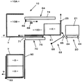
まず、図18に示しているように、本装置は、物品Xの箱Yへの挿入方向の後方に設けられ折りたたまれた製函用シートZを水平状態で複数積み重ねてストックさせるシートマガジン300(シート収容部に相当する)と、そのシートマガジン300の上方に設けられ、シートマガジン300から一番上に積み重ねられている製函用シートZを1枚づつ取り出すシート取出部400と、シート取出部400から取り出された製函用シートZを物品Xの挿入方向とは逆方向であるα方向の本装置の上流側に水平状態で水平方向に搬送する水平搬送部500と、水平搬送部500で搬送された製函用シートZを開口し、開口部を横にして箱形状に形成する製函部600と、製函部600で箱形状にされた箱Yを下方に搬送する下方搬送部700と、下方搬送部700にて搬送される箱Yの底フラップ部を折り込みテープにて貼り付けるテープ貼付部800と、テープ貼付部800の下方に配置され、箱Yに複数の物品Xを挿入する挿入部900と、挿入部900にて物品Xが挿入された箱Yを90度転倒させ開口部を上方にする箱倒立部1000と、箱倒立部1000で開口部が上方になった箱Yを物品Xの挿入方向であるβ方向の下流に搬送する箱排出部1100とで構成される。 First, as shown in FIG. 18, the present apparatus is a sheet magazine 300 (in which a plurality of folded box making sheets Z provided at the rear in the insertion direction of the article X into the box Y are stacked and stocked in a horizontal state. Sheet take-out
シートマガジン300は複数の製函用シートZを人が載置するシート供給位置310と、シート供給位置310のα方向(図19参照)に隣接して配置されたシートセット位置320を有している。また、シート供給位置310からシートセット位置320へ複数の製函用シートZの底部を支持して搬送する図示しない搬送ベルトが底部に設けられている。また、シート取出部400によって製函用シートZが1枚取り出されるごとに、複数の製函用シートZを上方に持ち上げる昇降部330がシートセット位置320に配置されている。この昇降部330は図示しない昇降モータにて製函用シートZの1枚の厚さピッチで上昇し、図示しない製函用シートZ検知部にてシートセット位置320の製函用シートZが全てなくなるとシート供給位置310と同じ高さまで下降する。なお、昇降部330は昇降時に搬送ベルトと干渉しないように配置されている。 The
シート取出部400はシートセット位置320の製函用シートZを上方より吸着し保持する吸盤を有した吸着部410を4つ備え、製函用シートZの四隅に配置されている。この吸着部410は図示しないバキューム装置と開閉バルブとにより製函用シートZを吸脱着可能になっている。 The sheet take-out
水平搬送部500は吸着部410にて上方に移動されてきた製函用シートZの側方下方を支持するサイド開閉フレーム510と、サイド開閉フレーム510と同一高さで隣接してα方向に固定されて設けられ、製函用シートZの側方下方を支持するサイド支持フレーム520と、サイド開閉フレーム510とサイド支持フレーム520との上方に設けられた1対の上方ベルト530とで構成される。 The
サイド開閉フレーム510はα方向と直交する水平面で水平の開閉スライド動作を行う。上方ベルト530はサイド開閉フレーム510とサイド支持フレーム520とで製函用シートZのサイドを上下方向から挟み、ベルトをα方向に駆動させることで、製函用シートZを水平状態で製函部600に搬送する。 The side opening /
製函部600は製函開閉フレーム610と、製函用シートZの上方を吸着して支持する上方吸着部620と、製函用シートZの下方より吸着して図示しない駆動部にて90度垂直に回転することで、製函用シートZを開口し、箱形状にして箱Yを形成する側方吸着部630と、箱Yのβ方向(図19参照)の側方の開口部から箱Yの内部に挿入され、箱Yの内側上方を水平支持することで箱Yの箱状態の形状を保持する水平シート開口部材640と、水平シート開口部材640と直交することで箱Yの内側下方を保持する垂直シート開口部材650とで構成される。この水平シート開口部材640と垂直シート開口部材650がシート開口部材に相当する。上方吸着部620は箱Yの側壁となる部位を吸着する4つの吸着部と、箱Yの蓋壁となる部位を吸着する2つの吸着部と、箱Yの底壁となる部位を吸着する2つの吸着部とで構成されている。側方吸着部630は箱Yの側壁となる部位を吸着する4つの吸着部で構成され、上方吸着部620とは異なり、箱Yの蓋壁や底壁となる部位を吸着する吸着部はない。また、上方吸着部620と側方吸着部630とは図示しないバキューム装置と開閉バルブとにより製函用シートZを吸脱着可能になっている。 The
下方搬送部700は8つの側方角保持部710と水平シート開口部材640と垂直シート開口部材650とを下方に移動させる図示しない開口部材移動手段とで構成される。8つの側方角保持部710は箱Yの上方と下方と箱Yの蓋側と底側の側部角を吸着しながら爪で箱Yの側部角を外側から保持する。箱Yは内部に挿入された両シート開口部材640、650と箱Yの外側から箱Yを保持する側方角保持部710を下方に移動させることで製函部600で形成された箱Yの立方体の形状を保持したまま下方に移動させる。 The
テープ貼付部800は下方搬送部700で搬送される途上の箱Yに対して物品Xの挿入側と反対方向に配置される。テープ貼付部800は箱Yの底フラップを図示しない底折部材で折り込み、底折部材で折り込まれ底が形成されたフラップに対してテープを貼り付けその底形状を固定する。 The
挿入部900は箱状態に形成された箱Yの側方にある開口部より複数の物品Xを挿入する。その動作は第1の実施形態と変わらない。箱倒立部(あるいは箱転倒部)1000は複数の物品Xが挿入された箱Yの底部が下になるように90度回転させる。その動作は第1の実施形態と変わらない。箱排出部1100は複数の物品Xが挿入された箱Yの開口部が上になった状態でβ方向に箱Yを排出する。その動作は第1の実施形態と変わらない。上記各駆動部や各吸着部等は図8に示される箱詰コントロールユニット100に接続され、制御が行われる。 The
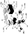
次に、図19を用いて動作を説明する。まず、シート供給位置310に人手にて折り畳まれた製函用シートZを複数水平状態にて積載して供給する。次に、前述の搬送ベルトにてシートセット位置320まで搬送される。次に昇降部330にてシートセット位置320に積載された製函用シートZを一括してシート取出部400まで上昇させる。シート取出部400では吸着部410にて最上部の製函用シートZの上面を吸着して水平搬送部500の高さまで上昇させる。 Next, the operation will be described with reference to FIG. First, a plurality of box-making sheets Z folded manually by the
次に水平搬送部500に搬送されてきた製函用シートZは開状態であったサイド開閉フレーム510が閉状態(1対のサイド開閉フレーム510が水平に接近する状態)になるため、サイド開閉フレーム510によって下方を支持される。 Next, the box-making sheet Z conveyed to the
次に吸着部410の吸引を停止させる。この状態で製函用シートZはサイド開閉フレーム510と上方ベルト530とによって挟み込まれている。次に上方ベルト530をα方向に駆動させることで製函用シートZはα方向に搬送される。このときサイド開閉フレーム510に延設されたサイド支持フレーム520と上方ベルト530とで挟持状態で製函用シートZは製函部600まで搬送される。製函部600まで製函用シートZが搬送されると上方吸着部620にて製函用シートZを上方より吸着し、保持する。このとき上方ベルト530は停止する。 Next, the suction of the
次に側方吸着部630が製函用シートZの下方(後に箱Yの側壁となる部分)を吸着して90度垂直方向に回転することで製函用シートZを開口させる。次に、水平シート開口部材640とやや垂直方向に対して傾斜した角度の垂直シート開口部材650とが同時にβ方向から、前記開口した部分に内部から挿入される。その後垂直シート開口部材650が回転して垂直になって、水平シート開口部材640と断面Tになることで、箱Yを内部から箱形状に保持する。次に、上方吸着部620と側方吸着部630との吸引が停止する。 Next, the
次に、水平シート開口部材640と垂直シート開口部材650とが下方のテープ貼付部800に移動させる。ここでは箱Yの底フラップを底折部材で折り込みながら、底部をテープで貼り付ける。そのため、箱Yの底部が形成される。このとき、テープを貼り付ける直前で側方角保持部710が箱Yの側方より近接し吸着する。また、爪にて箱Yの側部角を外側から保持する。テープの貼り付けが終了した後に、水平シート開口部材640と垂直シート開口部材650とが箱Yの内部から引き出され、側方角保持部710が下方に移動することで箱Yを挿入部900に移動させる。 Next, the horizontal
後は第1の実施形態と同様に物品Xを挿入させる。このとき、物品Xを2段積みにするときは側方角保持部710を物品の高さピッチで下方に移動させる。その後物品Xの挿入が完了した箱Yは箱倒立部1000で90度回転され、開口部が上になった状態で箱排出部1100によって排出する。 After that, the article X is inserted as in the first embodiment. At this time, when the articles X are stacked in two stages, the side
なお、シートマガジン300、シート取出部400、水平搬送部500、製函部600、下方搬送部700、テープ貼付部800、挿入部900、箱倒立部1000ではその部位での作業が完了するまで各部位間で箱Yや製函用シートZの移動は行われない。 In the
[本装置の特徴]
シート取出部400、水平搬送部500、シートマガジン300の直上方に配置させることで設置スペースの増加を防いでいる。また、挿入部900の上方に製函部600を直上方に配置させることで設置スペースの増加を防いでいる。つまり、各部位を立体的に配置させたため、設置スペースの増加を有効的に防いでいる。換言すれば、この装置の上部分に製函部600を付帯させたので、横方向(幅方向)の設置スペースが大きくならず、工場等の限られたスペースが十分に有効活用される。[Features of this device]
By arranging the sheet take-out
しかも、折り畳まれた製函用シートを水平状態で搬送するので、立体的に各部位を配置させても箱詰装置の高さ方向の設置スペースも抑えることができる。また、製函用シートZを水平状態で搬送させるため、垂直状態で搬送する場合よりも、シートを安定して搬送することができる。 Moreover, since the folded box-making sheet is conveyed in a horizontal state, the installation space in the height direction of the boxing device can be reduced even if each part is arranged three-dimensionally. Further, since the box-making sheet Z is transported in a horizontal state, the sheet can be transported more stably than when transported in a vertical state.
さらに、装置に対して箱の開口部を横方向とし、物品を箱に横方向から挿入するから、箱の上部を開口部として上方から物品を挿入する場合に比べて、高さ方向の設置スペースを抑えることができる。また、横方向からの挿入とすることで、物品の整列状態を良好に保持しながら箱に物品を挿入することができる。特に物品Xが軟弱な自立しない物品Xを複数挿入する場合に効果が高い。 Further, since the opening of the box is set in the horizontal direction with respect to the apparatus and the article is inserted into the box from the horizontal direction, the installation space in the height direction is compared with the case where the article is inserted from above with the upper part of the box as the opening. Can be suppressed. Further, by inserting from the lateral direction, it is possible to insert the article into the box while keeping the alignment state of the articles satisfactorily. In particular, the effect is high when a plurality of non-self-supporting articles X with soft articles X are inserted.
シート取出部が、シート収容部から水平搬送部に製函用シートを1枚ずつ取り出すので、作業者が水平搬送部にシートを載置する労力を省ける。 Since the sheet take-out unit takes out the box-forming sheets one by one from the sheet storage unit to the horizontal conveyance unit, the labor of placing the sheet on the horizontal conveyance unit can be saved.
製函部は、複数のシート開口部材を前記製函用シートの開口部に挿入し、互いに直交させることによって、シンプルな構造で箱を開口状態に確実に保持することができる。また、箱Yの内部から保持しているため、箱Yを下方搬送させる場合でも吸着等の新たな保持手段を特段必要としない。さらに、製函部600で外側から箱を開口させようとする側方吸着部630の吸着が開口の途中で外れても、箱が落下して装置外に脱落するようなことが防がれる。のみならず、シート開口部材の動作によって箱の開口は達成される。また、再使用の段ボールケース等は、フラップの状態が不安定なので、フラップの保持が困難になる。その結果、下方搬送部700に箱を受け渡す際、下方搬送部700の側方角保持部710が箱Yを確実に保持できずに、箱が潰れることがある。しかし、この点、シート開口部材が箱の開口状態を内側から保持するから、箱の保持に不安定な箇所が排除され、箱を下方搬送部700の側方角保持部710に確実に受け渡すことができるようになる。 The box making unit can hold the box in an open state with a simple structure by inserting a plurality of sheet opening members into the opening of the box making sheet and making them perpendicular to each other. Further, since the box Y is held from the inside, no new holding means such as suction is required even when the box Y is transported downward. Furthermore, even if the suction of the
排出部の上方に前記水平搬送部、前記製函部、前記下方搬送部、前記挿入部を配置することによって、より一層設置スペースを抑制することができる。 By disposing the horizontal conveyance unit, the box making unit, the lower conveyance unit, and the insertion unit above the discharge unit, installation space can be further reduced.
そして、箱倒立部1000で開口部が上方になった箱Yを物品Xの挿入方向であるβ方向の下流に搬送する箱排出部(特許請求の範囲の「排出搬送部」に相当する)1100は、前記水平搬送部500の直下で平行に配置されている。つまり、物品Xが詰められ、かつ開口部が上を向いた姿勢の箱Yは、最終的に、箱排出部1100に排出される。その場合に、箱排出部1100は、上方の水平搬送部500の直下で平行に配置されているから、最初の製函用シートZから最後の箱Yまでの移送経路は側面視でコ字状になり、いわば縦循環経路となって、前記のように、横方向(幅方向)の設置スペースと、高さ方向の設置スペースに加えて、長さ方向の設置スペースも抑えられ、その結果、本装置の縦・横・高さの3方向の全ての立体的サイズ、ひいては占有スペースの極小化が図られ、ますます工場等の限られたスペースが有効利用される。 And the box discharge part (equivalent to the "discharge conveyance part" of a claim) 1100 which conveys the box Y where the opening part became the upper part in the box
[第4の実施の形態]
次に、本発明の第4の実施形態を図20〜図23を用いて説明する。この第4実施形態は、製函部600のシート開口部材640,650が箱の開口時には互いに離反するように動作する点で、それが互いに直交するように動作する前記第3実施形態と異なる。以下の説明において、上、下、左、右、前、後というときは、図18に示す方向をいう。[Fourth Embodiment]
Next, a fourth embodiment of the present invention will be described with reference to FIGS. The fourth embodiment is different from the third embodiment in that the
図20及び図21に示すように、この実施形態では、水平シート開口部材640は、左右2つのブレード641,642に分割されている。一方、垂直シート開口部材650は、単一のブレード651である。左右のブレード641,642はガイドレール等(図示省略)に沿って左右方向に移動自在であり、単一のブレードはその下方でリンク等(図示省略)によって左上の上方位置と右下の下方位置との間で旋回自在である(旋回中心は固定されている:図中、旋回中心を黒丸で示した)。製函部600には、左右のブレード641,642をそれぞれ前記のように独立して移動させる駆動手段643,644(図23参照)、例えば流体シリンダと、下ブレード651を前記のように旋回させる駆動手段652(図23参照)、例えば駆動モータあるいは流体シリンダとが備えられている。また、下ブレード651の旋回半径を調製する調製手段653(図23参照)、例えば流体シリンダも備えられている。 As shown in FIGS. 20 and 21, in this embodiment, the horizontal
3つのブレード641,642,651は、箱Yに挿入される前は、互いに近接し合っている。すなわち、左ブレード641は右へ、右ブレード642は左へ、下ブレード651は左上の上方位置へ移動している。製函部600において、箱Yが側方吸着部630によりやや開口されると、集合状態のブレード641,642,651は、そのやや開いた開口に向かって突入する。そして、前記駆動手段643,644,652により、互いに離反するように動く。すなわち、左ブレード641は左へ、右ブレード642は右へ、下ブレード651は右下の下方位置(右ブレード642の右位置の直下方にある)へ移動する。その結果、左ブレード641は、箱Yの左上角部を内側から外方に押圧し、右ブレード642は、箱Yの右上角部を内側から外方に押圧し、下ブレード651は、箱Yの右下角部を内側から外方に押圧する。このとき、調製手段653によって下ブレード651が箱Yの右下角部に届くように下ブレード651の旋回半径が調製される。これにより、箱Yが3つのブレード641,642,651によって開口状態に保持される。 The three
その場合に、ブレード641,642,651の離反動作は、側方吸着部630の開口動作とほぼ同期して行われ、側方吸着部630の開口動作を補助する程度にやや遅れ気味に動作する。製函部600には、3つのブレード641,642,651を前記のように一体に箱Yの開口内に挿入させ、かつ開口内から引き出す前後駆動手段610(図23参照)、例えば流体シリンダが備えられている。 In this case, the separating operation of the
一方、図22にも示すように、この実施形態では、右ブレード642と、下ブレード651とに、フラップ折込部材645,646が取り付けられている。すなわち、各ブレード642,651のフラップ折込部材645,646は、ブレード642,651が箱Yに挿入されたときに、蓋フラップFに対応する位置に設けられている。そして、右ブレード642のフラップ折込部材645は右側方に張り出しており、右移動時に、箱Yの開口部の周囲で立っている右側の蓋フラップFを外側へ折り込む。一方、下ブレード651のフラップ折込部材646は下方に張り出しており、下移動時に、箱Yの開口部の周囲で立っている下側の蓋フラップFを外側へ折り込む。 On the other hand, as shown in FIG. 22, in this embodiment,
さらに、製函部600には、3つのブレード641,642,651を一体に上下移動させる上下駆動手段620(図23参照)、例えば駆動モータあるいは流体シリンダが備えられている。したがって、この駆動手段620によって、ブレード641,642,651が離反状態のままで下方移動されると、箱Yは開口状態が保持されたまま下方へ搬送されることになる。そして、搬送された箱Yは、下方搬送部700に備えられた前記側方角保持部710に受け渡される。 Further, the
図23に示すように、この実施形態においては、コントロールユニット2000は、前記各手段610,620,643,644,652,653を制御することにより、まず、集合状態のブレード641,642,651を一体に箱Y内に突入させ、次に、互いに離反させて箱Yの開口を保持させ、その状態で一体に下方移動させ、下方搬送部700の側方角保持部710に受け渡した後、集合させ、次に、箱Y内から引き出し、上方移動させて、次の箱Yの開口に待機する、…という一連の動作を繰り返す。 As shown in FIG. 23, in this embodiment, the control unit 2000 controls each of the
その場合に、この実施形態では、製函部600で開口される箱Yは、右基準、上基準、前基準で開口される。つまり、箱Yのサイズが変更されたときは、それに対応するように、左側、下側、後側の部材が位置変更される。そのため、前記コントロールユニット2000は、入力手段1200から入力される箱Yのサイズに関する情報に基き、前記左ブレード641の左移動位置と、下ブレード651の下方位置とを可変制御するように、左ブレード641の駆動手段643と、下ブレード651の調製手段653とを制御する。つまり、図20と図21とを比較すると、基準になる右ブレード642の右移動位置は変化しないが、その他の左ブレード641の左移動位置及び下ブレード651の下方位置は箱Yのサイズに応じて変化している。
[本装置の特徴]In this case, in this embodiment, the box Y opened by the
[Features of this device]
本装置では、シート開口部材641,642,651が互いに離反するように動作するので、箱Yの角部を内側から押し広げるようになり、箱Yを精度よく正確に位置決めして開口保持することが可能となる。その場合に、シート開口部材641,642,651は、内側から箱Yを支持するので、製函部600で外側から箱Yを開口させようとする側方吸着部630の吸着が開口の途中で外れても、箱Yが落下して本装置外に脱落するようなことが防がれるばかりでなく、シート開口部材641,642,651の動作によって箱Yの開口が最後まで支障なく達成される、という第3実施形態と同様の効果も奏される。 In this apparatus, since the
また、シート開口部材641,642,651の離反時、すなわち、箱Yの開口時に、箱Yの開口部の周囲で起立している蓋フラップがシート開口部材642,651によって同時に外側へ容易に折り込まれるので、本装置の作業時間の短縮化が図られる。 Further, when the
そして、箱Yを開口保持した後、箱Yを内側から支持するシート開口部材641,642,651が、箱Yを開口状態に保持したまま下方へ搬送するから、例えば下方搬送部700において側方角保持部710が箱Yを外側から把持する場合でも、その側方角保持部710とシート開口部材641,642,651との部材同士の干渉が回避でき、箱Yを良好に下方搬送部700に受け渡すことが可能となる。 Then, after the box Y is held open, the
[第5の実施の形態]
次に、本発明の第5の実施形態を図24以下を用いて説明する。この第5実施形態は、箱倒立部1000において、下方搬送部700の側方角保持部710から受け渡され、物品が挿入された箱Yが、その受け渡し地点の直下方で90度回転する点で、その箱の回転が、箱が受け渡し地点からある程度後方に後退してからである前記第1実施形態(図6参照)と異なる。[Fifth Embodiment]
Next, a fifth embodiment of the present invention will be described with reference to FIG. In the fifth embodiment, in the box inverted
図24に示すように、箱倒立部(特許請求の範囲の「排出部」に相当する)1000には、それまで横方向を向いていた開口部が上方向を向くように箱Yを回転させる回転部材1010が備えられている。回転部材1010は、第1実施形態におけるL字状の箱排出シート51と類似の構成であり、支点1020を中心に下流の箱排出部1100側に90度回転可能に構成されている。 As shown in FIG. 24, the box Y is rotated in the box inverted portion (corresponding to the “discharge portion” in the claims) 1000 so that the opening portion that has been oriented in the lateral direction is directed upward. A rotating
ここで、前述したように、箱Yのサイズが変更されたときは、それに対応するように、左側、下側、後側の部材が位置変更される。そのため、回転部材1010は、上下位置及び前後位置が変更可能に構成されている。下方搬送部700の側方角保持部710からの箱Yの受け渡し地点が一定であるので、例えば、図25に示すように、サイズの小さい箱Yの場合は、受け渡し時における箱Yの下面がより高い位置にあるから、回転部材1010は上方移動する。また、例えば、図24に示したように、サイズの大きい箱Yの場合は、受け渡し時における箱Yの後面がより後方位置にあるから、回転部材1010は後方移動する。 Here, as described above, when the size of the box Y is changed, the positions of the left, lower, and rear members are changed so as to correspond thereto. Therefore, the rotating
図26に示すように、箱倒立部1000には、回転部材1010を前記のように上下移動させる駆動手段1030、例えば流体シリンダと、前後移動させる駆動手段1040、例えば流体シリンダとが備えられている。また、回転部材1010を前記のように90度回転させる駆動手段1050、例えば駆動モータも備えられている。 As shown in FIG. 26, the box inverted
一方、回転部材1010は、左右2つに分割されており、この点も第1実施形態におけるL字状の箱排出シート51と類似している(図5参照)。そして、箱Yのサイズが変更されたときは、それに対応するように、左側の回転部材1010が左右方向において位置変更可能に構成されている。例えば、サイズの大きい箱Yの場合は、受け渡し時における箱Yの左面がより左側方にあるから、左側の回転部材1010は左方移動する。 On the other hand, the rotating
図26に示すように、箱倒立部1000には、左回転部材1010を前記のように左右移動させる駆動手段1060、例えば流体シリンダが備えられている。そして、コントロールユニット3000は、入力手段1200から入力される箱Yのサイズに関する情報に基き、両回転部材1010の上下位置と、両回転部材1010の前後位置と、前記左回転部材1010の左右位置とを可変制御するように、前記各駆動手段1030,1040,1060を制御する。 As shown in FIG. 26, the box inverted
このような構成に加えて、図24に示すように、箱倒立部1000には、箱Yの回転時に箱Yを保持する保持部材1080と、回転後に箱Yを下流の箱排出部1100へ押し出す押出部材1090とがさらに備えられている。 In addition to such a configuration, as shown in FIG. 24, the box inverted
保持部材1080は左右一対あり、回転部材1010に受け渡された箱Yの左右側面を左右両側から挟み付けて保持する。図26に示すように、箱倒立部1000には、保持部材1080を前記のように駆動させる駆動手段1081、例えば流体シリンダが備えられている。この駆動手段1081は、コントロールユニット3000によってその動作が制御される。 The holding
一方、押出部材1090は左右両回転部材1010にそれぞれ組み込まれている。押出部材1090は、下方搬送部700の側方角保持部710からの箱Yの受け渡し時には、その箱Yの受け面(載置面)を提供する。そして、回転部材1010が90度回転した後、適宜の駆動手段1091(図26参照)、例えば流体シリンダによって、下流の箱排出部1100側に突出移動することにより、載置していた箱Yを箱排出部1100側に押し出し、排出する。このとき保持部材1080による箱Yの保持は解除される。なお、この押出部材1090の駆動手段1091もコントロールユニット3000によってその動作が制御される。 On the other hand, the pushing
[本装置の特徴]
本装置では、箱倒立部1000において、物品Xが挿入され、下方搬送部700の側方角保持部710から受け渡された箱Yは、開口部が横方向から上方向に姿勢が回転されてから排出されるので、箱Y内の物品Xの外への飛び出しが抑制される。しかも、箱Yが受け渡された直後にその場で回転するので、箱Y内の物品Xの外への飛び出しがより一層抑制される。[Features of this device]
In this apparatus, the box X is inserted into the box inverted
しかも、箱倒立部1000において、箱Yが回転されるときは、箱Yが保持部材1080により保持され、そして、回転された後は、開口部が上方向を向いた箱Yが押出部材1090により下流へ押し出されるので、箱Yを高速で安定に回転させ、かつ排出することができて、本装置の処理能力の向上に資することができる。 Moreover, when the box Y is rotated in the box inverted
1 箱詰システム
10 箱詰装置
20 搬送装置
100 箱詰装置コントロールユニット
200 搬送装置コントロールユニット
300 シートマガジン
400 シート取出部
500 水平搬送部
600 製函部
700 下方搬送部
800 テープ貼付部
900 挿入部
1000 箱倒立部
1100 箱排出部DESCRIPTION OF
Claims (6)
Priority Applications (1)
| Application Number | Priority Date | Filing Date | Title |
|---|---|---|---|
| JP2003436897A JP4472983B2 (en) | 2003-10-20 | 2003-12-27 | Boxing equipment |
Applications Claiming Priority (2)
| Application Number | Priority Date | Filing Date | Title |
|---|---|---|---|
| JP2003359688 | 2003-10-20 | ||
| JP2003436897A JP4472983B2 (en) | 2003-10-20 | 2003-12-27 | Boxing equipment |
Publications (2)
| Publication Number | Publication Date |
|---|---|
| JP2005145558A JP2005145558A (en) | 2005-06-09 |
| JP4472983B2 true JP4472983B2 (en) | 2010-06-02 |
Family
ID=34703016
Family Applications (1)
| Application Number | Title | Priority Date | Filing Date |
|---|---|---|---|
| JP2003436897A Expired - Fee Related JP4472983B2 (en) | 2003-10-20 | 2003-12-27 | Boxing equipment |
Country Status (1)
| Country | Link |
|---|---|
| JP (1) | JP4472983B2 (en) |
Families Citing this family (11)
| Publication number | Priority date | Publication date | Assignee | Title |
|---|---|---|---|---|
| JP5258276B2 (en) * | 2007-12-11 | 2013-08-07 | 森永製菓株式会社 | Tray molding supply method and tray molding supply device |
| JP2009249017A (en) * | 2008-04-09 | 2009-10-29 | Ishida Co Ltd | Carton making apparatus and boxing apparatus equipped with the same |
| JP2018154344A (en) * | 2017-03-15 | 2018-10-04 | 株式会社イシダ | Box transfer device |
| CN107458027B (en) * | 2017-08-23 | 2024-06-04 | 贵州裕同包装科技有限公司 | Automatic foam seat device that adorns of wine box |
| JP6967781B2 (en) * | 2018-02-22 | 2021-11-17 | 株式会社イシダ | Boxing device |
| JP7180857B2 (en) * | 2018-02-27 | 2022-11-30 | 株式会社イシダ | Carton-making, boxing, and sealing equipment |
| CN111196392B (en) * | 2020-03-12 | 2025-01-03 | 绿诺能源科技(深圳)有限公司 | Automatic box loading equipment and its claw mechanism |
| JP7388983B2 (en) | 2020-06-22 | 2023-11-29 | 株式会社京都製作所 | packaging equipment |
| CN113264225B (en) * | 2021-06-30 | 2022-07-08 | 兰剑智能科技股份有限公司 | Flexible turnover box packaging machine |
| CN116873307A (en) * | 2023-07-11 | 2023-10-13 | 惠州固尔琦智能设备有限公司 | A carton unpacking equipment |
| CN118025605B (en) * | 2024-04-12 | 2024-06-21 | 敷尔敏(湖南)药业有限公司 | Automatic packaging machine is used in repair subsides production |
-
2003
- 2003-12-27 JP JP2003436897A patent/JP4472983B2/en not_active Expired - Fee Related
Also Published As
| Publication number | Publication date |
|---|---|
| JP2005145558A (en) | 2005-06-09 |
Similar Documents
| Publication | Publication Date | Title |
|---|---|---|
| JP4722906B2 (en) | Packaging box manufacturing and loading devices | |
| JP5499133B2 (en) | Boxing system | |
| US9334070B2 (en) | Package filling plant, a packing device and method for grouping a packing formation of packages and containers, and a packing device and method for grouping a packing formation of packages and containers | |
| JP6228757B2 (en) | Boxing equipment | |
| JPH0656105A (en) | Device for manufacturing carton | |
| CN101516734A (en) | Conveyance device, and box packing device and box packing system with the same | |
| JP5753643B2 (en) | Cardboard boxing system | |
| EP1553021A1 (en) | Method and assembly for filling a box | |
| KR101929419B1 (en) | Wrap around caser | |
| JP4472983B2 (en) | Boxing equipment | |
| US12492029B2 (en) | Packaging system and method for feeding flat packaging materials to a packaging system | |
| JP3708185B2 (en) | Boxing method and boxing device | |
| US7475768B2 (en) | Accumulation device and box packing system having same | |
| JP2015020777A (en) | Boxing device | |
| JPH10230909A (en) | Two-tier packaging apparatus, carton pickup apparatus, and apparatus for building up carton | |
| JP6228766B2 (en) | Accumulator | |
| KR102599074B1 (en) | unit product packaging apparatus | |
| JP2004155428A (en) | Casing apparatus | |
| JPH0671404U (en) | Long box packing equipment | |
| CN118871353A (en) | Box making machine | |
| JPH0648402A (en) | Apparatus for boxing cans | |
| JP2001010602A (en) | Boxing system | |
| CN117460671A (en) | Packaging methods and systems for packaging more than one item in a box | |
| CN221738298U (en) | Boxing and conveying device for producing aerosol bottles | |
| JP5648951B2 (en) | Boxing equipment |
Legal Events
| Date | Code | Title | Description |
|---|---|---|---|
| A621 | Written request for application examination |
Free format text: JAPANESE INTERMEDIATE CODE: A621 Effective date: 20061117 |
|
| RD03 | Notification of appointment of power of attorney |
Free format text: JAPANESE INTERMEDIATE CODE: A7423 Effective date: 20090618 |
|
| A977 | Report on retrieval |
Free format text: JAPANESE INTERMEDIATE CODE: A971007 Effective date: 20091120 |
|
| A131 | Notification of reasons for refusal |
Free format text: JAPANESE INTERMEDIATE CODE: A131 Effective date: 20091222 |
|
| A521 | Request for written amendment filed |
Free format text: JAPANESE INTERMEDIATE CODE: A523 Effective date: 20100118 |
|
| TRDD | Decision of grant or rejection written | ||
| A01 | Written decision to grant a patent or to grant a registration (utility model) |
Free format text: JAPANESE INTERMEDIATE CODE: A01 Effective date: 20100302 |
|
| A01 | Written decision to grant a patent or to grant a registration (utility model) |
Free format text: JAPANESE INTERMEDIATE CODE: A01 |
|
| A61 | First payment of annual fees (during grant procedure) |
Free format text: JAPANESE INTERMEDIATE CODE: A61 Effective date: 20100304 |
|
| FPAY | Renewal fee payment (event date is renewal date of database) |
Free format text: PAYMENT UNTIL: 20130312 Year of fee payment: 3 |
|
| R150 | Certificate of patent or registration of utility model |
Ref document number: 4472983 Country of ref document: JP Free format text: JAPANESE INTERMEDIATE CODE: R150 Free format text: JAPANESE INTERMEDIATE CODE: R150 |
|
| FPAY | Renewal fee payment (event date is renewal date of database) |
Free format text: PAYMENT UNTIL: 20140312 Year of fee payment: 4 |
|
| R250 | Receipt of annual fees |
Free format text: JAPANESE INTERMEDIATE CODE: R250 |
|
| R250 | Receipt of annual fees |
Free format text: JAPANESE INTERMEDIATE CODE: R250 |
|
| R250 | Receipt of annual fees |
Free format text: JAPANESE INTERMEDIATE CODE: R250 |
|
| R250 | Receipt of annual fees |
Free format text: JAPANESE INTERMEDIATE CODE: R250 |
|
| R250 | Receipt of annual fees |
Free format text: JAPANESE INTERMEDIATE CODE: R250 |
|
| R250 | Receipt of annual fees |
Free format text: JAPANESE INTERMEDIATE CODE: R250 |
|
| R250 | Receipt of annual fees |
Free format text: JAPANESE INTERMEDIATE CODE: R250 |
|
| R250 | Receipt of annual fees |
Free format text: JAPANESE INTERMEDIATE CODE: R250 |
|
| R250 | Receipt of annual fees |
Free format text: JAPANESE INTERMEDIATE CODE: R250 |
|
| R250 | Receipt of annual fees |
Free format text: JAPANESE INTERMEDIATE CODE: R250 |
|
| LAPS | Cancellation because of no payment of annual fees |