JP4472389B2 - Zoom lens barrel - Google Patents

Zoom lens barrel Download PDF

Info

Publication number
JP4472389B2
JP4472389B2 JP2004075064A JP2004075064A JP4472389B2 JP 4472389 B2 JP4472389 B2 JP 4472389B2 JP 2004075064 A JP2004075064 A JP 2004075064A JP 2004075064 A JP2004075064 A JP 2004075064A JP 4472389 B2 JP4472389 B2 JP 4472389B2
Authority
JP
Japan
Prior art keywords
frame
state
optical axis
lens barrel
group
Prior art date
Legal status (The legal status is an assumption and is not a legal conclusion. Google has not performed a legal analysis and makes no representation as to the accuracy of the status listed.)
Expired - Fee Related
Application number
JP2004075064A
Other languages
Japanese (ja)
Other versions
JP2005265992A5 (en
JP2005265992A (en
Inventor
信将 田中
直弘 土田
Current Assignee (The listed assignees may be inaccurate. Google has not performed a legal analysis and makes no representation or warranty as to the accuracy of the list.)
Olympus Corp
Original Assignee
Olympus Corp
Priority date (The priority date is an assumption and is not a legal conclusion. Google has not performed a legal analysis and makes no representation as to the accuracy of the date listed.)
Filing date
Publication date
Application filed by Olympus Corp filed Critical Olympus Corp
Priority to JP2004075064A priority Critical patent/JP4472389B2/en
Publication of JP2005265992A publication Critical patent/JP2005265992A/en
Publication of JP2005265992A5 publication Critical patent/JP2005265992A5/ja
Application granted granted Critical
Publication of JP4472389B2 publication Critical patent/JP4472389B2/en
Anticipated expiration legal-status Critical
Expired - Fee Related legal-status Critical Current

Links

Images

Description

本発明は、ズームレンズ鏡筒の構造、特に沈胴状態での配置構造に関する。   The present invention relates to a structure of a zoom lens barrel, and more particularly to an arrangement structure in a retracted state.

従来の沈胴可能なズームレンズ鏡筒において、図11の枠部材配置を示す断面図に示すような枠部材配置(沈胴状態)を有する鏡筒101は、カメラ本体102に固定される固定枠103と、レンズ保持枠を進退駆動するための枠部材としての回転枠104と、移動枠105とを有してなる。   In a conventional retractable zoom lens barrel, a barrel 101 having a frame member arrangement (collapsed state) as shown in a cross-sectional view of the frame member arrangement in FIG. 11 includes a fixed frame 103 fixed to the camera body 102. , A rotation frame 104 as a frame member for driving the lens holding frame forward and backward, and a moving frame 105.

上記従来のレンズ鏡筒においては、回転枠104は、固定枠103の雌ヘリコイド103aに螺合する雄ヘリコイド104aにより、回転かつ進退自在に支持される。一方、移動枠105は、回転枠104の円周溝104bに摺動自在に嵌入するガイド突起105bを有し、さらに、固定枠103の直進ガイド溝103bに摺動自在に嵌入するガイド突起105aを有している。従って、移動枠105は、固定枠103により回転規制された状態で回転枠103とともに光軸O方向に進退駆動される。図11は、レンズ鏡筒101の沈胴状態を示しているが、この沈胴状態にあるとき、回転枠104と移動枠105は、ともにカメラ本体102の前端面側に繰り込まれている。   In the conventional lens barrel described above, the rotating frame 104 is supported by the male helicoid 104a that is screwed into the female helicoid 103a of the fixed frame 103 so as to be able to rotate and advance and retract. On the other hand, the moving frame 105 has a guide projection 105b that is slidably fitted into the circumferential groove 104b of the rotating frame 104, and further has a guide projection 105a that is slidably fitted into the straight guide groove 103b of the fixed frame 103. Have. Accordingly, the moving frame 105 is driven to move forward and backward in the optical axis O direction together with the rotating frame 103 in a state in which the rotation is restricted by the fixed frame 103. FIG. 11 shows the retracted state of the lens barrel 101. When the lens barrel 101 is in the retracted state, the rotating frame 104 and the moving frame 105 are both retracted to the front end face side of the camera body 102.

上述した図11に示した構造を有するズームレンズ鏡筒101の場合、沈胴状態にあるとき、回転枠104の後端面とカメラ本体102との間に移動枠105のガイド突起105aが介在した状態となっている。言い換えれば、沈胴状態での回転枠104がカメラ本体102に対してガイド突起105aの厚みtだけ前方にあり、沈胴状態でのレンズ鏡筒の短縮化が十分になされているとはいえない。   In the case of the zoom lens barrel 101 having the structure shown in FIG. 11 described above, the guide projection 105a of the moving frame 105 is interposed between the rear end surface of the rotating frame 104 and the camera body 102 when in the retracted state. It has become. In other words, the rotating frame 104 in the retracted state is in front of the camera body 102 by the thickness t of the guide projection 105a, and it cannot be said that the lens barrel in the retracted state is sufficiently shortened.

本発明は、上述の問題を解決するためになされたものであり、非撮影状態で全長を短縮可能なズームレンズ鏡筒において、非撮影状態の鏡筒全長の十分な短縮化が可能なズームレンズ鏡筒を提供することを目的とする。   The present invention has been made to solve the above-described problem, and in a zoom lens barrel capable of reducing the overall length in a non-photographing state, the zoom lens capable of sufficiently shortening the overall length of the lens barrel in a non-photographing state An object is to provide a lens barrel.

本発明の請求項1記載のズームレンズ鏡筒は、非撮影状態のときは、撮影可能状態のときよりも全長を短縮可能なズームレンズ鏡筒において、第一の枠と、上記第一の枠に対し回転しながら光軸方向に移動する第二の枠と、上記第二の枠を第一の枠に対し回転させ、光軸方向に移動させる第一の駆動手段と、上記第二の枠と伴に光軸方向に移動し、上記第二の枠に対し回転可能に支持された第三の枠と、上記第三の枠を第一の枠に対し非回転とするため、上記第三の枠と上記第一の枠との間に設けられた直進手段と、撮影可能状態では上記第三の枠を上記第二の枠に対し回転可能に、かつ、光軸方向には相対的に移動しないように支持するための円周溝部分と、この円周溝部分と係合して摺動する凸部と、撮影可能状態から非撮影状態に移行する際中に上記第三の枠を上記第二の枠に対し光軸方向に相対移動させるため、上記円周溝部分から連続して形成され上記凸部と係合して上記第二の枠の移動方向とは逆方向に上記第三の枠を駆動するカム溝部分とを有する第二の駆動手段とを有し、上記直進手段は、上記第一の枠の直進溝と上記第三の枠の後端部にある凸とで形成され、上記非撮影状態にあるときは、上記凸が上記第二の枠の後端面に形成された凹部分に位置する。 The zoom lens barrel according to claim 1 of the present invention is a zoom lens barrel capable of shortening the overall length in the non-shooting state than in the shooting enabled state. A second frame that moves in the direction of the optical axis while rotating relative to the first frame, a first drive means that rotates the second frame relative to the first frame and moves in the direction of the optical axis, and the second frame And the third frame supported so as to be rotatable with respect to the second frame, and the third frame non-rotating with respect to the first frame. And a straight-advancing means provided between the first frame and the first frame, and the third frame can be rotated relative to the second frame in a shootable state and relatively to the optical axis direction. A circumferential groove portion for supporting the movement so as not to move, a convex portion that engages and slides with the circumferential groove portion, and shifts from a photographable state to a non-photographing state. In order to move the third frame relative to the second frame in the optical axis direction, the second frame is formed continuously from the circumferential groove portion and engaged with the convex portion. of the moving direction possess a second drive means having a cam groove portion for driving the third frame in the opposite direction, the straight section of the first frame rectilinear grooves and the third When the projection is formed in the rear end portion of the frame and in the non-photographing state, the projection is located in the concave portion formed on the rear end surface of the second frame.

本発明によれば、非撮影状態で全長を短縮可能なズームレンズ鏡筒において、非撮影状態での鏡筒全長の十分な短縮化が可能なズームレンズ鏡筒を提供することができる。   According to the present invention, it is possible to provide a zoom lens barrel capable of sufficiently shortening the entire length of the lens barrel in the non-photographing state in the zoom lens barrel capable of shortening the total length in the non-photographing state.

以下、本発明の実施の形態を図に基づいて説明する。
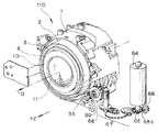
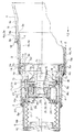
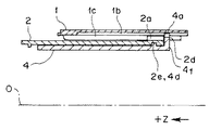
図1は、本発明の一実施形態であるズームレンズ鏡筒の外観を示す斜視図である。図2は、上記ズームレンズ鏡筒が装着される銀塩カメラのレンズ鏡筒沈胴状態での撮影光軸に沿った断面図である。図3は、上記ズームレンズ鏡筒の撮影可能なワイド状態での撮影光軸に沿った断面図である。図4は、上記ズームレンズ鏡筒の撮影可能なテレ状態での撮影光軸に沿った断面図である。図5,6は、上記ズームレンズ鏡筒の分解斜視図である。図7は、上記ズームレンズ鏡筒に内蔵されるフォーカスユニットの分解斜視図である。図8は、上記ズームレンズ鏡筒における回転枠の内周部の展開図である。図9は、上記ズームレンズ鏡筒の沈胴状態における図8のA−A断面図を示す。図10は、上記ズームレンズ鏡筒の撮影可能状態における図8のB−B断面図を示す。
Hereinafter, embodiments of the present invention will be described with reference to the drawings.
FIG. 1 is a perspective view showing an appearance of a zoom lens barrel that is an embodiment of the present invention. FIG. 2 is a cross-sectional view taken along the photographing optical axis in the retracted state of the lens barrel of the silver halide camera to which the zoom lens barrel is attached. FIG. 3 is a cross-sectional view of the zoom lens barrel taken along the photographing optical axis in a wide state where photographing is possible. FIG. 4 is a cross-sectional view of the zoom lens barrel along the photographing optical axis in a telephoto state where photographing is possible. 5 and 6 are exploded perspective views of the zoom lens barrel. FIG. 7 is an exploded perspective view of the focus unit built in the zoom lens barrel. FIG. 8 is a development view of the inner periphery of the rotating frame in the zoom lens barrel. FIG. 9 is a cross-sectional view taken along the line AA of FIG. 8 in the retracted state of the zoom lens barrel. FIG. 10 is a cross-sectional view taken along the line BB of FIG. 8 in a state where the zoom lens barrel can be photographed.

なお、以下の説明において、ズームレンズ鏡筒(レンズ鏡筒と記載する)の被写体側を前方側とし(前方方向を+Zとする)、結像側を後方側(または、背面側)とする(後方方向を−Z方向とする)。また、回転方向は、前方側から見たときの回転方向で示す。   In the following description, the subject side of a zoom lens barrel (described as a lens barrel) is the front side (the forward direction is + Z), and the imaging side is the rear side (or the back side) ( The backward direction is taken as the -Z direction). The rotation direction is indicated by the rotation direction when viewed from the front side.

本実施形態のレンズ鏡筒110は、図2等に示すように銀塩カメラ100に組み込まれるレンズシャッタタイプのズームレンズ鏡筒であって、該カメラ100には、ズーム式光学ファインダ装置が組み込まれているものとする。また、レンズ鏡筒110は、非撮影時に各枠部材を固定枠内に略繰り込んで鏡筒の全長を撮影可能時より短縮することができる、所謂、沈胴式レンズ鏡筒である。   The lens barrel 110 of the present embodiment is a lens shutter type zoom lens barrel incorporated in the silver halide camera 100 as shown in FIG. 2 and the like, and the camera 100 incorporates a zoom optical viewfinder device. It shall be. The lens barrel 110 is a so-called collapsible lens barrel in which each frame member is substantially retracted into the fixed frame during non-photographing so that the entire length of the lens barrel can be shortened compared to when photographing is possible.

レンズ鏡筒110は、図1〜6等に示すようにカメラ外装カバー120内にてカメラ本体130に支持される第一の枠である固定枠1と、固定枠1内に組み込まれる枠部材として、固定枠1に対して回転,進退自在に支持される第二の枠である回転枠2と、固定枠1に対して回転規制され、回転枠2とともに進退移動する第三の枠である移動枠4と、回転枠2とともに回転し、移動枠4に対して進退駆動されるカム枠3と、移動枠4により回転規制され、かつ、カム枠3とともに進退移動する第四の枠であるフロートキー5と、フロートキー5により回転規制され、かつ、カム枠3により進退駆動される第一群枠6と、フロートキー5により回転規制され、かつ、カム枠3により進退駆動されるフォーカスユニット7および第三群枠8と、フォーカスユニット7と第三群枠8を離間させる方向に付勢する圧縮バネで形成される付勢バネ9と、光軸Oを有する撮影光学系(ズームレンズ)として第一群枠6に保持される第一群レンズ11,第二群枠23に保持されるフォーカシングレンズ群である第二群レンズ12,第三群枠8に保持される第三群レンズ13と、第一群枠6とフォーカスユニット7の間に配される蛇腹遮光ゴム17と、各枠部材間に配されるリング状の遮光ゴム18,19,20とを主に有してなる。   The lens barrel 110 includes a fixed frame 1 that is a first frame supported by the camera body 130 within the camera exterior cover 120 and a frame member that is incorporated into the fixed frame 1 as shown in FIGS. Rotating frame 2 that is a second frame that is supported so as to be able to rotate and advance and retract relative to fixed frame 1, and movement that is a third frame that is restricted in rotation relative to fixed frame 1 and moves forward and backward with rotating frame 2 A frame 4, a cam frame 3 that rotates together with the rotating frame 2 and is driven forward and backward with respect to the moving frame 4, and a float that is a fourth frame that is rotationally restricted by the moving frame 4 and moves forward and backward together with the cam frame 3. A key 5, a first group frame 6 whose rotation is restricted by the float key 5 and driven to advance and retract by the cam frame 3, and a focus unit 7 whose rotation is restricted by the float key 5 and which is driven to advance and retract by the cam frame 3 And the third group frame 8, and The first group frame 6 is held as a photographing optical system (zoom lens) having an urging spring 9 formed by a compression spring that urges the cus unit 7 and the third group frame 8 in a direction to separate them. The first group lens 11, the second group lens 12 which is a focusing lens group held by the second group frame 23, the third group lens 13 held by the third group frame 8, the first group frame 6 and the focus unit. 7 mainly includes bellows light shielding rubber 17 disposed between the ring members 7 and ring-shaped light shielding rubbers 18, 19, and 20 disposed between the frame members.

固定枠1は、円環形状部材であって、固定枠1には内周部に第一の駆動手段である雌ヘリコイドネジ(以下、ヘリコイドネジは、ヘリコイドと記載する)1aと、該ヘリコイドに重畳する直進手段としての直進溝1bが設けられ、内周部に光軸Oに沿ったロングギヤ挿入用凹部1cが設けられる。   The fixed frame 1 is a ring-shaped member, and the fixed frame 1 has a female helicoid screw (hereinafter referred to as a helicoid screw) 1a as a first driving means on the inner peripheral portion, and a helicoid. A rectilinear groove 1b is provided as a superimposing rectilinear means, and a long gear insertion recess 1c along the optical axis O is provided in the inner peripheral portion.

直進溝1bのうち、下方に配置される直進溝1b1には、2つのピン穴1fとビス穴1e等が設けられる。2つのピン穴1fには、それぞれズーム検出ピン37A,37Bが外周側から直進溝1b1内にその先端部が突出する状態で出没自在に挿入される。固定枠1の直進溝1b1の外側の外周位置にズームエンコーダ89であるズーム位置検出スイッチ部40を構成するワイド検出スイッチ接片38A,テレ検出スイッチ接片38Bおよび検出スイッチコモン接片39とがビス72,73をビス穴1e等に螺着して固着される。一方のズーム検出ピン37Aの下端部がコモン接片39の後側端部39aに当接し、他方のズーム検出ピン37Bの下端部がコモン接片39の前側端部39bに当接している。後,前側端部39a,39bは、常時はワイド検出スイッチ接片38A,テレ検出スイッチ接片38Bに接触(オン状態)している。繰り出された移動枠4のガイド突起4a(後述)によりズーム検出ピン37A,37Bの何れかが押圧されると、ワイド検出スイッチ接片38A,テレ検出スイッチ接片38Bがオフ状態に切り替わり、移動枠4のワイド端位置、または、テレ端位置が検出される。なお、ワイド検出スイッチ接片38A,テレ検出スイッチ接片38B,コモン接片39の端部ブラシ部は、図示しない接続用フレキシブルプリント基板に接触して保持され、その出力は、後述するCPU91に入力される。   Of the rectilinear grooves 1b, the rectilinear grooves 1b1 disposed below are provided with two pin holes 1f and screw holes 1e. Zoom detection pins 37A and 37B are inserted into the two pin holes 1f, respectively, so that they can be protruded and retracted in a state in which their tip portions protrude from the outer peripheral side into the rectilinear groove 1b1. A wide detection switch contact piece 38A, a tele detection switch contact piece 38B and a detection switch common contact piece 39 constituting the zoom position detection switch unit 40, which is the zoom encoder 89, are provided at the outer peripheral position of the fixed frame 1 outside the rectilinear groove 1b1. 72 and 73 are screwed and fixed to the screw holes 1e and the like. The lower end of one zoom detection pin 37 </ b> A is in contact with the rear end 39 a of the common contact piece 39, and the lower end of the other zoom detection pin 37 </ b> B is in contact with the front end 39 b of the common contact piece 39. The front end portions 39a and 39b are always in contact (on state) with the wide detection switch contact piece 38A and the tele detection switch contact piece 38B. When one of the zoom detection pins 37A and 37B is pressed by a guide projection 4a (described later) of the moving frame 4 that has been extended, the wide detection switch contact piece 38A and the tele detection switch contact piece 38B are switched to the OFF state, and the movement frame 4 wide end positions or tele end positions are detected. Note that the end brush portions of the wide detection switch contact piece 38A, the tele detection switch contact piece 38B, and the common contact piece 39 are held in contact with a connection flexible printed circuit board (not shown), and the output is input to a CPU 91 described later. Is done.

ギヤ挿入用凹部1cには、回転枠駆動用ロングギヤ36が挿入され、ロングギヤ36は、前方の軸穴1dと後方部の固定されるギヤ取り付け板36aとによって取り付けられ、その回転軸は、光軸Oと平行に回転自在に支持される。   A rotary frame driving long gear 36 is inserted into the gear insertion recess 1c, and the long gear 36 is mounted by a front shaft hole 1d and a gear mounting plate 36a fixed at the rear portion, and the rotation axis is an optical axis. O is supported in parallel with O.

ロングギヤ36は、ズーム駆動時、ズームモータ64によりギヤ列67等を介して回転駆動される。すなわち、図1に示すようにズームモータ64の出力軸に固着されるピニオン65は、ギヤ列67の入力側ギヤに噛合しており、ギヤ列67の出力ギヤ側は、ネジギヤ68側に噛合している。ネジギヤ68の回転は、出力ギヤ69側に伝達される。出力ギヤ69は、ロングギヤ36に常時噛合しているので、ズームモータ64の回転は、ロングギヤ36側に伝達される。   The long gear 36 is rotationally driven by the zoom motor 64 via the gear train 67 and the like during zoom driving. That is, as shown in FIG. 1, the pinion 65 fixed to the output shaft of the zoom motor 64 meshes with the input side gear of the gear train 67, and the output gear side of the gear train 67 meshes with the screw gear 68 side. ing. The rotation of the screw gear 68 is transmitted to the output gear 69 side. Since the output gear 69 is always meshed with the long gear 36, the rotation of the zoom motor 64 is transmitted to the long gear 36 side.

ズームモータ64の回転量は、ズームモータ出力軸に固着されるスリット板65aの回転量を検出するズームエンコーダ89であるフォトインターラプタ66により検知される。   The amount of rotation of the zoom motor 64 is detected by a photo interrupter 66 that is a zoom encoder 89 that detects the amount of rotation of the slit plate 65a fixed to the zoom motor output shaft.

回転枠2は、円環形状部材であって、回転枠2には後端外周部にギヤ部2cと第一の駆動手段である雄ヘリコイド2aとが設けられる。後方内周部には内周に沿った第二の駆動手段である複数の円周溝2eが設けられ、円周溝2eには、第二の駆動手段であるカム溝部2g,2fが連続して形成されている(図8)。カム溝部2fの端部には、移動枠4のガイドピン4dの組み立て挿入口2hが設けられる。また、回転枠2の後端面2dには、カム溝部2f,2gに対応した状態で該後端面2dから凹んだ形状の複数の凹部2iが設けられる。さらに、内周部には光軸O方向に沿った複数の直進溝2bが設けられている。   The rotating frame 2 is a ring-shaped member, and the rotating frame 2 is provided with a gear portion 2c and a male helicoid 2a as a first driving means on the outer peripheral portion of the rear end. A plurality of circumferential grooves 2e, which are second driving means, are provided along the inner circumference in the rear inner peripheral portion, and cam groove portions 2g, 2f, which are second driving means, are continuous with the circumferential groove 2e. (FIG. 8). An assembly insertion port 2h for the guide pin 4d of the moving frame 4 is provided at the end of the cam groove 2f. Further, the rear end surface 2d of the rotary frame 2 is provided with a plurality of concave portions 2i having a shape recessed from the rear end surface 2d in a state corresponding to the cam groove portions 2f and 2g. Further, a plurality of rectilinear grooves 2b along the direction of the optical axis O are provided in the inner peripheral portion.

回転枠2は、雄ヘリコイド2aを固定枠1の内周部の雌ヘリコイド1aに螺合させて固定枠1の内周部に嵌入される。そして、回転枠2は、固定枠1に装着されたロングギヤ36によりこれと噛合するギヤ部2cを介して回転駆動され、固定枠1に対して回転しながら光軸O方向に進退移動する。   The rotating frame 2 is fitted into the inner peripheral portion of the fixed frame 1 by screwing the male helicoid 2 a with the female helicoid 1 a on the inner peripheral portion of the fixed frame 1. The rotating frame 2 is rotationally driven by a long gear 36 attached to the fixed frame 1 via a gear portion 2 c that meshes with the long gear 36, and moves forward and backward in the direction of the optical axis O while rotating with respect to the fixed frame 1.

移動枠4は、円環形状部材であって、移動枠4には後端部4fの外周部に外径方向に突出する直進手段である複数のガイド突起(凸部)4aと、ガイド突起4aの前方位置にて外方に突出する第二の駆動手段である複数のガイドピン4dと、内周部に雌ヘリコイド4b、および、光軸O方向に沿った直進溝4cとが設けられており、さらに、内外周部を貫通する2本の螺旋状逃げ溝4eが設けられている。   The moving frame 4 is a ring-shaped member, and the moving frame 4 includes a plurality of guide protrusions (convex parts) 4a that are rectilinearly protruding means on the outer peripheral portion of the rear end portion 4f, and a guide protrusion 4a. Are provided with a plurality of guide pins 4d, which are the second drive means projecting outward at the front position, a female helicoid 4b on the inner peripheral portion, and a rectilinear groove 4c along the optical axis O direction. Furthermore, two spiral relief grooves 4e penetrating the inner and outer peripheral portions are provided.

移動枠4は、ガイド突起4aを固定枠1の直進溝1bに摺動自在に嵌入させた状態で回転枠2の内周部に回転自在に嵌合して保持される。レンズ鏡筒が撮影可能状態にあるときは、移動枠4のガイドピン4dは、回転枠2の円周溝2eに摺動自在に嵌入しており、移動枠4は、固定枠1に対して直進溝1bで回転規制され、かつ、回転枠2に対して円周溝2eにより光軸O方向に一体の状態で回転枠2の内周部に支持され、進退移動する(図8,10)。また、非撮影状態(沈胴状態)では、回転枠2の沈胴回動位置への回動によって、ガイドピン4dがカム溝部2gを通過することによって回転枠2に対して所定量(ガイド突起4aの厚み相当分)前方に移動してカム溝部2fに嵌入する。移動枠4のガイド突起4aは、回転枠2の凹部2iに嵌り込む(図8,9)。   The moving frame 4 is rotatably fitted and held on the inner peripheral portion of the rotating frame 2 in a state where the guide protrusion 4a is slidably fitted in the rectilinear groove 1b of the fixed frame 1. When the lens barrel is in a shootable state, the guide pin 4d of the moving frame 4 is slidably fitted into the circumferential groove 2e of the rotating frame 2, and the moving frame 4 is in contact with the fixed frame 1. The rotation is restricted by the rectilinear groove 1b, and is supported by the inner peripheral portion of the rotating frame 2 in the optical axis O direction by the circumferential groove 2e with respect to the rotating frame 2, and moves forward and backward (FIGS. 8 and 10). . Further, in a non-photographing state (collapsed state), the guide pin 4d passes through the cam groove 2g due to the rotation of the rotary frame 2 to the retracted rotation position, and a predetermined amount (the guide projection 4a of the guide projection 4a) The portion corresponding to the thickness) moves forward and fits into the cam groove 2f. The guide protrusion 4a of the moving frame 4 fits into the recess 2i of the rotating frame 2 (FIGS. 8 and 9).

カム枠3は、円環形状部材であって、カム枠3には後端外周部に雄ヘリコイド3aが設けられる。また、後方内周部には複数のガイド突起3eが設けられる。また、内周部には雌ヘリコイド3bと、光軸O方向に対して斜行するズーム用カムとして各3本のカム溝3c,3dが設けられる。また、上記後端の雄ヘリコイド3aが設けられる部分に外方に突出する2本のガイドピン14が固着される。   The cam frame 3 is an annular member, and the cam frame 3 is provided with a male helicoid 3a on the outer periphery of the rear end. A plurality of guide protrusions 3e are provided on the rear inner periphery. In addition, a female helicoid 3b and three cam grooves 3c and 3d are provided on the inner peripheral portion as zoom cams that are inclined with respect to the optical axis O direction. Further, two guide pins 14 protruding outward are fixed to a portion where the rear end male helicoid 3a is provided.

カム溝3cは、後述するフォーカスユニット7の第二群ガイド枠21のカムフォロア15と嵌合するカム溝であって、第二群ガイド枠21を介して第二群枠23に保持されるフォーカシングレンズの第二群レンズ12をズーミングのために光軸O方向に進退させるためのズーム用カムである。但し、カム溝3cには、ズーミング時の第二群レンズ12の光学的必要移動量を制限するために後述するように該必要移動量に対して不足するカム筋が形成されているものとする。合焦駆動時に上記ズーミングに光軸O方向に不足する移動量を合焦駆動量に加算した第二群レンズ12の補正駆動がなされる。   The cam groove 3 c is a cam groove that fits with a cam follower 15 of a second group guide frame 21 of the focus unit 7 described later, and is a focusing lens that is held on the second group frame 23 via the second group guide frame 21. This is a zoom cam for advancing and retracting the second group lens 12 in the optical axis O direction for zooming. However, the cam groove 3c is formed with cam streaks that are insufficient with respect to the required movement amount as will be described later in order to limit the required optical movement amount of the second lens group 12 during zooming. . The correction driving of the second lens group 12 is performed by adding the amount of movement that is insufficient in the optical axis O direction during zooming to the focusing driving amount during focusing driving.

カム溝3dは、第三群枠8のカムフォロア16と嵌合するカム溝であって、第三群枠8に保持される第三群レンズ13をズーミングのために光軸O方向に進退させるためのズーム用カムである。   The cam groove 3d is a cam groove fitted to the cam follower 16 of the third group frame 8, and is used to advance and retract the third group lens 13 held by the third group frame 8 in the optical axis O direction for zooming. This is a zoom cam.

カム枠3は、移動枠4の内周部の雌ヘリコイド4bに雄ヘリコイド3aを螺合させた状態で嵌合され、かつ、ガイドピン14が逃げ溝4eを挿通した状態で回転枠2の直進溝2bに摺動自在に嵌入させて組み込まれる。従って、カム枠3は、回転枠2とともに回転し、かつ、移動枠4に対して相対的に光軸O方向に進退移動する。   The cam frame 3 is fitted in a state in which the male helicoid 3a is screwed to the female helicoid 4b on the inner peripheral portion of the moving frame 4, and the rotating frame 2 moves straight with the guide pin 14 inserted through the escape groove 4e. The groove 2b is slidably fitted into the groove 2b. Accordingly, the cam frame 3 rotates together with the rotating frame 2 and moves forward and backward in the optical axis O direction relative to the moving frame 4.

フロートキー5は、円環形状部材であって、フロートキー5には外周後端部に外径方向に突出する複数のガイド突起5aと、外周後方部に周方向に沿ったガイド溝5dと、外周部に光軸O方向に沿った直進溝5eと、内外周を貫通する光軸O方向に沿った各3本の直進ガイド溝5b,5cが設けられる。   The float key 5 is a ring-shaped member, and the float key 5 includes a plurality of guide protrusions 5a protruding in the outer radial direction at the outer peripheral rear end portion, and a guide groove 5d extending in the circumferential direction at the outer peripheral rear portion, A rectilinear groove 5e along the optical axis O direction and three rectilinear guide grooves 5b and 5c along the optical axis O direction penetrating the inner and outer peripheries are provided on the outer peripheral portion.

フロートキー5は、ガイド突起5aを移動枠4の直進溝4cに摺動自在に嵌入させ、さらに、ガイド溝5dにカム枠3のガイド突起3eを摺動自在に嵌入させた状態で組み付けられる。従って、フロートキー5は、移動枠4によって回転が規制され、かつ、光軸O方向にカム枠3と一体で進退移動する。   The float key 5 is assembled in a state where the guide protrusion 5a is slidably fitted into the rectilinear groove 4c of the moving frame 4, and the guide protrusion 3e of the cam frame 3 is slidably fitted into the guide groove 5d. Therefore, the rotation of the float key 5 is restricted by the moving frame 4 and moves forward and backward integrally with the cam frame 3 in the optical axis O direction.

第一群枠6は、円環形状部材であって、第一群枠6には後端外周部に雄ヘリコイド6aと、内周部に光軸O方向に延びる直進ガイド凸部6bが設けられる。さらに、中央開口部に第一群レンズ11が保持され、その前面部に飾り板10が固着される。   The first group frame 6 is a ring-shaped member, and the first group frame 6 is provided with a male helicoid 6a on the outer peripheral portion of the rear end and a straight guide convex portion 6b extending in the optical axis O direction on the inner peripheral portion. . Further, the first lens group 11 is held in the central opening, and the decorative plate 10 is fixed to the front surface thereof.

第一群枠6は、直進ガイド凸部6bをフロートキー5の直進ガイド溝5bに摺動自在に嵌入させ、かつ、雄ヘリコイド6aをカム枠3の雌ヘリコイド3bに螺合させて組み込まれる。従って、第一群枠6は、フロートキー5によって回転規制された状態でカム枠3の回転および進退移動にともなって光軸O方向に直進移動する。   The first group frame 6 is incorporated by sliding the straight guide convex portion 6 b into the straight guide groove 5 b of the float key 5 slidably and screwing the male helicoid 6 a with the female helicoid 3 b of the cam frame 3. Accordingly, the first group frame 6 moves straight in the direction of the optical axis O as the cam frame 3 rotates and advances and retracts while being restricted by the float key 5.

フォーカスユニット7は、図2,5,7等に示すように第二群ガイド枠21と、フォーカシングスレンズ,シャッタの駆動源が装着され、第二群ガイド枠21の後側に取り付けられるLD地板22と、シャッタ羽根,遮光羽根及びフォーカシングレンズである第二群レンズ等が組み込まれ、フォーカシング時に第二群ガイド枠21に対して光軸O方向に相対駆動される第二群枠23と、第二群枠23の前面に取り付けられるシャッタ蓋25と、第二群ガイド枠21の前面に取り付けられる枠蓋26と、第二群枠23を光軸O方向に摺動自在に支持するガイドロッド27とを主に有してなる。   As shown in FIGS. 2, 5, and 7, the focus unit 7 is mounted with a second group guide frame 21, a focusing lens, and a shutter drive source, and is mounted on the rear side of the second group guide frame 21. 22, a shutter blade, a light shielding blade, a second lens group that is a focusing lens, and the like are incorporated, and a second group frame 23 that is driven relative to the second group guide frame 21 in the optical axis O direction during focusing, A shutter lid 25 attached to the front surface of the second group frame 23, a frame lid 26 attached to the front surface of the second group guide frame 21, and a guide rod 27 that slidably supports the second group frame 23 in the direction of the optical axis O. And mainly.

LD地板22は、中央開口部22aを有する枠部材であって、その前面側にシャッタ羽根,遮光羽根の駆動源であるプランジャソレノイド装置55と、合焦駆動の駆動源であるフォーカスモータ41と、合焦駆動用ギヤ列46と、合焦駆動用ギヤ列46を介して第二群枠23を進退駆動する合焦駆動機構部と、フォーカスモータ回転量検出用フォトインタラプタ61と、シャッタ羽根移動位置検出用フォトインタラプタ63等が組み込まれる。このLD地板22は、第二群ガイド枠21に対して背面側からフック22cで仮止めした後、ビス挿通穴22bに挿通させたビス71a、および、ビス挿通穴22dを挿通させたビス71bを第二群ガイド枠21に螺着させて固定される。   The LD base plate 22 is a frame member having a central opening 22a, and on the front side thereof, a plunger solenoid device 55 that is a driving source of shutter blades and light shielding blades, a focus motor 41 that is a driving source of focusing drive, A focus drive gear train 46, a focus drive mechanism for driving the second group frame 23 forward and backward via the focus drive gear train 46, a focus motor rotation amount detection photo interrupter 61, and a shutter blade movement position A photo interrupter 63 for detection and the like are incorporated. The LD base plate 22 is temporarily fixed to the second group guide frame 21 with a hook 22c from the back side, and then a screw 71a inserted into the screw insertion hole 22b and a screw 71b inserted through the screw insertion hole 22d. The second group guide frame 21 is fixed by screwing.

プランジャソレノイド装置55は、ソレノイド部58と、プランジャ56と、該ソレノイド部と該プランジャとの間に介在され、該プランジャを突出方向(シャッタ羽根閉方向)に付勢するプランジャバネ57とを有している。プランジャ56のスライド方向は、光軸Oとの垂直面に沿った方向とする。プランジャ56の先端には後述するシャッタ駆動レバー29の端部29bが当接する。   The plunger solenoid device 55 includes a solenoid part 58, a plunger 56, and a plunger spring 57 that is interposed between the solenoid part and the plunger and biases the plunger in the protruding direction (shutter blade closing direction). ing. The sliding direction of the plunger 56 is a direction along a plane perpendicular to the optical axis O. An end portion 29b of a shutter drive lever 29 described later abuts on the tip of the plunger 56.

フォーカスモータ41は、光軸Oと平行方向に沿った出力軸を有しており、該出力軸には、ピニオン42が固着されている。ピニオン42は、合焦駆動用ギヤ列46の初段ギヤ47に噛合する。この出力軸の回転量は、合焦駆動用ギヤ列46中のギヤ48の軸に取り付けられたスリット板62の回転を検出するフォーカスエンコーダ60であるフォトインターラプタ61によって検出される。   The focus motor 41 has an output shaft along a direction parallel to the optical axis O, and a pinion 42 is fixed to the output shaft. The pinion 42 meshes with the first gear 47 of the focusing drive gear train 46. The rotation amount of the output shaft is detected by a photo interrupter 61 that is a focus encoder 60 that detects the rotation of the slit plate 62 attached to the shaft of the gear 48 in the focusing drive gear train 46.

合焦駆動用ギヤ列46の終段ギヤ49は、一体的に固着される光軸Oと平行な合焦駆動機構部の送りネジ50を有しており、送りネジ50には合焦駆動機構部の駆動用ナット52が螺合している。なお、この送りネジ50まわりの合焦駆動機構部の詳細については、後で説明する。   The final stage gear 49 of the focusing drive gear train 46 has a feed screw 50 of a focusing drive mechanism portion parallel to the optical axis O fixed integrally, and the feed screw 50 has a focusing drive mechanism. The drive nut 52 of the part is screwed. The details of the focusing drive mechanism around the feed screw 50 will be described later.

第二群ガイド枠21は、中央開口部21aを有する枠部材であって、外周部3ヶ所に凸部21bが設けられ、その凸部にそれぞれカムフォロア15が固着される。   The second group guide frame 21 is a frame member having a central opening 21a, and is provided with convex portions 21b at three outer peripheral portions, and the cam followers 15 are fixed to the convex portions, respectively.

フォーカスユニット7に内蔵される第二群ガイド枠21の凸部21bがフロートキー5内部の直進ガイド溝5bに嵌入した状態で光軸O方向に直進ガイドされて支持される。そして、第二群ガイド枠21は、ズーム駆動時、カム枠3のカム溝3cに嵌入するカムフォロア15を介してカム枠3の回転に伴って相対的に進退駆動される。   The convex portion 21b of the second group guide frame 21 built in the focus unit 7 is supported by being linearly guided in the direction of the optical axis O while being fitted in the linear guide groove 5b inside the float key 5. The second group guide frame 21 is relatively advanced and retracted with the rotation of the cam frame 3 through the cam follower 15 fitted in the cam groove 3c of the cam frame 3 during zoom driving.

第二群枠23は、中央にシャッタ開口部23aを有する枠部材であって、第二群レンズおよびシャッタ装置が組み込まれている。すなわち、この第二群枠23には、該開口部23aの後方側に第二群レンズ12(図2)が保持され、前面側にシャッタ装置として撮影光路を開閉する一対のシャッタ羽根である第一のシャッタ羽根31と第二のシャッタ羽根32が一対の軸である支持ピン23dと支持ピン23eに回動自在に支持されている。さらに、シャッタ装置として撮影光の漏れを遮光する遮光羽根33が支持ピン23fにより回動可能に支持されている。また、背面側上方部の光軸O方向に突出する軸部23gにはシャッタ駆動レバー29が軸穴29aにて回動可能に取り付けられている。また、第二群枠23の上方部に光軸O方向と平行なスリーブ28が接着固定される。該スリーブの光軸Oを挟んだ対向位置の外方に突出する回り止め用ガイド凸部23bが設けられる。   The second group frame 23 is a frame member having a shutter opening 23a at the center, and a second group lens and a shutter device are incorporated therein. That is, the second group frame 23 includes a pair of shutter blades that hold the second group lens 12 (FIG. 2) on the rear side of the opening 23a and open and close the photographing optical path as a shutter device on the front side. One shutter blade 31 and second shutter blade 32 are rotatably supported by a support pin 23d and a support pin 23e, which are a pair of shafts. Further, a light shielding blade 33 that shields the leakage of photographing light as a shutter device is rotatably supported by a support pin 23f. Further, a shutter drive lever 29 is rotatably attached to a shaft portion 23g protruding in the optical axis O direction on the rear side upper portion through a shaft hole 29a. A sleeve 28 parallel to the direction of the optical axis O is bonded and fixed to the upper part of the second group frame 23. An anti-rotation guide convex portion 23b is provided that protrudes outward at a position facing the optical axis O of the sleeve.

スリーブ28は、まず、第二群枠23に対してガタのある状態で挿入される。そして、該スリーブの内径部が第二群レンズ12の光軸Oと平行で、かつ、光軸Oから所定の距離離間した状態で位置するように治具等で位置決めした状態で第二群枠23に接着,固定される。なお、このスリーブ28には、第二群枠23を摺動自在に支持するガイドロッド27が嵌入される。   First, the sleeve 28 is inserted into the second group frame 23 with a backlash. The second group frame is positioned with a jig or the like so that the inner diameter portion of the sleeve is positioned parallel to the optical axis O of the second group lens 12 and spaced from the optical axis O by a predetermined distance. It is bonded and fixed to 23. The sleeve 28 is fitted with a guide rod 27 that slidably supports the second group frame 23.

シャッタ駆動レバー29は、プランジャ56によって駆動される被駆動部材であり、かつ、遮光羽根を含むシャッタ羽根を回動駆動する駆動部材である。そして、このシャッタ駆動レバー29は、軸部23gに回動自在に嵌合する軸穴29aと、プランジャ56の先端に当接する端部29bと、第二群枠23のピン挿通長穴23cを挿通して前方側に突出し、シャッタ羽根,遮光羽根に係合するシャッタ駆動ピン29cを有している。   The shutter drive lever 29 is a driven member that is driven by the plunger 56 and is a drive member that rotationally drives the shutter blades including the light shielding blades. The shutter drive lever 29 is inserted through a shaft hole 29a that is rotatably fitted to the shaft portion 23g, an end portion 29b that contacts the tip of the plunger 56, and a pin insertion long hole 23c of the second group frame 23. Then, it has a shutter drive pin 29c that protrudes forward and engages the shutter blade and the light shielding blade.

シャッタ駆動レバー29は、シャッタバネ30により時計回り(前方より見て)に付勢されている。その付勢方向は、シャッタ駆動レバー29の端部29bがプランジャ56の先端側に当接する方向であり、かつ、シャッタ羽根31,32,遮光羽根33を開放する方向である。このシャッタバネ30のシャッタ駆動レバー29に対する付勢力は、プランジャ56側の付勢バネ57の付勢力より弱い。従って、プランジャソレノイド装置55がオフ状態になるとシャッタ駆動レバー29は、付勢バネ57の付勢力によってプランジャ56を介してシャッタ閉方向に回動駆動される。   The shutter drive lever 29 is urged clockwise (viewed from the front) by a shutter spring 30. The urging direction is a direction in which the end portion 29b of the shutter drive lever 29 is in contact with the distal end side of the plunger 56, and a direction in which the shutter blades 31, 32 and the light shielding blade 33 are opened. The biasing force of the shutter spring 30 against the shutter drive lever 29 is weaker than the biasing force of the biasing spring 57 on the plunger 56 side. Therefore, when the plunger solenoid device 55 is turned off, the shutter drive lever 29 is rotationally driven in the shutter closing direction via the plunger 56 by the biasing force of the biasing spring 57.

なお、シャッタ駆動レバー29とプランジャ56とは、フォーカス駆動時に光軸O方向に相対移動することからプランジャ56の先端との当接状態を維持するためにシャッタ駆動レバー29の端部29bは、光軸O方向に平行である軸穴29a方向と平行に延びた形状を有している。   Since the shutter drive lever 29 and the plunger 56 move relative to each other in the direction of the optical axis O during focus driving, the end portion 29b of the shutter drive lever 29 is light-tight in order to maintain a contact state with the tip of the plunger 56. It has a shape extending in parallel with the direction of the shaft hole 29a which is parallel to the direction of the axis O.

第一のシャッタ羽根31は、シャッタ開口部23aを第二のシャッタ羽根32と協働して開閉可能な遮光部を有している。そして、シャッタ羽根31は、第二群枠23の前面側にて支持ピン23dに嵌入し、かつ、駆動用長穴をシャッタ駆動レバー29の駆動ピン29cに嵌入した状態で回動可能に支持される。   The first shutter blade 31 has a light shielding portion that can open and close the shutter opening 23 a in cooperation with the second shutter blade 32. The shutter blade 31 is rotatably supported in a state where the shutter blade 31 is fitted into the support pin 23d on the front side of the second group frame 23 and the drive slot is fitted into the drive pin 29c of the shutter drive lever 29. The

第二のシャッタ羽根32は、シャッタ開口23aを第一のシャッタ羽根31と協働して開閉可能な開口縁部をもつ遮光部を有している。すなわち、第二のシャッタ羽根32は、第一のシャッタ羽根31に対してシャッタ閉状態において該開口部23a上にて食い合わせ部分(重なる部分)を形成する。このシャッタ羽根32は、第二群枠23の前方側でシャッタ羽根31の前面に重畳させた状態で支持ピン23eに嵌入し、かつ、駆動用長穴をシャッタ駆動レバー29の駆動ピン29cに嵌入した状態で回動可能に支持される。   The second shutter blade 32 has a light-shielding portion having an opening edge that can open and close the shutter opening 23 a in cooperation with the first shutter blade 31. That is, the second shutter blade 32 forms a biting portion (overlapping portion) on the opening 23 a in the shutter closed state with respect to the first shutter blade 31. The shutter blade 32 is fitted into the support pin 23e in a state of being superimposed on the front surface of the shutter blade 31 on the front side of the second group frame 23, and the drive elongated hole is fitted into the drive pin 29c of the shutter drive lever 29. In such a state, it is supported so as to be rotatable.

遮光羽根33は、シャッタ開口部23aをシャッタ羽根31,32とで遮蔽した状態でのシャッタ羽根31,32の重畳部からの光漏れを遮断し、かつ、シャッタ開時には、シャッタ羽根31とともにシャッタ開口部23aから退避可能な遮光部を有している。この遮光羽根33は、第二群枠23の前面側にてシャッタ羽根32の前面側の遮光部の縁部を覆った状態で該シャッタ羽根32をシャッタ羽根31とで挟んだ状態で配置される。その取り付け状態で支持ピン23fに嵌入し、かつ、駆動用長穴をシャッタ駆動レバー29の駆動ピン29cに嵌入させた状態で回動可能に支持される。   The light shielding blade 33 blocks light leakage from the overlapping portion of the shutter blades 31 and 32 in a state where the shutter opening portion 23a is shielded by the shutter blades 31 and 32, and when the shutter is opened, the shutter opening together with the shutter blade 31 It has a light-shielding part that can be retracted from the part 23a. The light shielding blade 33 is arranged in a state where the shutter blade 32 is sandwiched between the shutter blades 31 while covering the edge of the light shielding portion on the front surface side of the shutter blade 32 on the front surface side of the second group frame 23. . In the attached state, the support pin 23f is fitted, and the drive elongate hole is fitted to the drive pin 29c of the shutter drive lever 29 so as to be rotatably supported.

遮光羽根33の前面にさらに遮光シート24を乗せて、覆った状態とする。なお、遮光シート24には、シャッタ開口部23aと等しい大きさの中央開口部24aや駆動ピン29cの逃げ穴24cや第二群枠付勢バネ35の逃げ部24b等が設けられている。   A light shielding sheet 24 is further placed on the front surface of the light shielding blade 33 to cover it. The light shielding sheet 24 is provided with a central opening 24a having the same size as the shutter opening 23a, a relief hole 24c of the drive pin 29c, a relief 24b of the second group frame biasing spring 35, and the like.

シャッタ羽根31,32と遮光羽根33および遮光シート24が組み込まれた第二群枠23には、その前面にシャッタ蓋25が第二群枠23の係止ピン23h,23i,23jで係止されて装着され、ユニット化される。なお、シャッタ蓋25には、駆動ピン29cの逃げ穴25cや第二群枠付勢バネ35の逃げ部25b等が設けられている。   The shutter lid 25 is locked to the front surface of the second group frame 23 in which the shutter blades 31 and 32, the light shielding blade 33, and the light shielding sheet 24 are incorporated by the locking pins 23h, 23i, and 23j of the second group frame 23. Are installed and unitized. The shutter cover 25 is provided with a relief hole 25c of the drive pin 29c, a relief portion 25b of the second group frame biasing spring 35, and the like.

ユニット化された第二群枠23は、第二群ガイド枠21に対してその前面側からガイド凸部23bを第二群ガイド枠21の光軸Oと平行に形成されたガイド凹部21dに摺動自在に嵌入させた状態で装着される。さらに、その装着状態で枠蓋26を第二群ガイド枠21の前面にガイド枠の位置決めピンで位置決めした状態ではめ込み、枠蓋26の係止穴部26bを第二群ガイド枠21のフック部21fに係止させて仮止め状態とする。そこで、ガイドロッド27を枠蓋26のロッド支持穴26cに挿通させてその先端部を第二群ガイド枠21のロッド支持穴21cに圧入して固定する。なお、その固定状態でガイドロッド27には、枠蓋26と第二群枠23の間に第二群枠付勢バネ35が圧縮状態で挿入される。   The unitized second group frame 23 slides the guide projection 23b from the front side of the second group guide frame 21 to a guide recess 21d formed in parallel with the optical axis O of the second group guide frame 21. It is mounted in a state where it is freely inserted. Further, the frame lid 26 is fitted to the front surface of the second group guide frame 21 with the positioning pin of the guide frame in the mounted state, and the locking hole portion 26b of the frame lid 26 is hooked to the hook portion of the second group guide frame 21. 21f is engaged to provide a temporarily fixed state. Therefore, the guide rod 27 is inserted into the rod support hole 26c of the frame lid 26, and the tip portion thereof is press-fitted into the rod support hole 21c of the second group guide frame 21 and fixed. In the fixed state, the second group frame biasing spring 35 is inserted into the guide rod 27 between the frame lid 26 and the second group frame 23 in a compressed state.

上述したLD地板22に組み込まれる合焦駆動機構部は、フォーカスモータ41により駆動されるギヤ列46の終段ギヤ49に一体的に固着される光軸Oと平行な送りネジ50と、送りネジ50に螺合する駆動用ナット52とを有してなる。   The focusing drive mechanism unit incorporated in the LD base plate 22 described above includes a feed screw 50 parallel to the optical axis O fixed integrally to the final gear 49 of the gear train 46 driven by the focus motor 41, and a feed screw. 50 and a drive nut 52 that is screwed to 50.

合焦駆動時にフォーカスモータ41の出力軸が回転駆動されると、終段ギヤ49の回転に伴って送りネジ50を介して駆動用ナット52が移動するので、第二群枠23は、駆動用ナット52を介して付勢バネ35の付勢力に抗して押圧され、第二群ガイド枠21およびLD地板22に対して相対的に光軸Oと平行なZ方向に進退し、合焦駆動される。   When the output shaft of the focus motor 41 is rotationally driven during focusing driving, the driving nut 52 moves via the feed screw 50 as the final gear 49 rotates, so that the second group frame 23 is used for driving. It is pressed against the urging force of the urging spring 35 via the nut 52, moves forward and backward in the Z direction parallel to the optical axis O relative to the second group guide frame 21 and the LD base plate 22, and drives to focus. Is done.

第三群枠8は、中央開口部に第三群レンズ13を保持する円板形状の枠部材であって、第三群枠には、外周部に3つの直進ガイド凸部8aが設けられ、該凸部上には3本のカムフォロア16がそれぞれ固着されている。   The third group frame 8 is a disk-shaped frame member that holds the third group lens 13 in the central opening, and the third group frame is provided with three rectilinear guide convex portions 8a on the outer peripheral portion, Three cam followers 16 are fixed to the convex portions, respectively.

第三群枠8は、フロートキー5の内周部にて直進ガイド凸部8aをフロートキー5の直進ガイド溝5cに摺動自在に嵌入させた状態でフォーカスユニット7の後方位置に光軸O方向に進退自在に挿入される。そして、第三群枠8のカムフォロア16は、カム枠3の内周のカム溝3dに摺動自在に嵌入される。従って、第三群枠8は、光軸O方向に直進ガイドされた状態でカム枠3の回転および進退移動にともなってカム溝3dによって進退移動する。   The third group frame 8 has an optical axis O at a rear position of the focus unit 7 in a state in which the straight guide protrusion 8a is slidably fitted in the straight guide groove 5c of the float key 5 at the inner periphery of the float key 5. It is inserted so that it can move forward and backward. The cam follower 16 of the third group frame 8 is slidably fitted into the cam groove 3 d on the inner periphery of the cam frame 3. Accordingly, the third group frame 8 moves forward and backward by the cam groove 3d as the cam frame 3 rotates and advances and retracts while being guided linearly in the direction of the optical axis O.

第三群枠8とフォーカスユニット7のLD地板22との間には、圧縮バネである付勢バネ9が挿入されており、常時、離間する方向に付勢力が作用している。従って、第三群枠8のカムフォロア16とカム溝3dとの間の嵌合ガタおよび第二群ガイド枠21のカムフォロア15とカム溝3cとの間の嵌合ガタがない状態で第三群枠8および第二ガイド枠21(第二群枠23)は、進退移動することになる。   A biasing spring 9 that is a compression spring is inserted between the third group frame 8 and the LD base plate 22 of the focus unit 7, and a biasing force is always acting in the direction of separation. Accordingly, in the state where there is no fitting backlash between the cam follower 16 of the third group frame 8 and the cam groove 3d and no backlash between the cam follower 15 of the second group guide frame 21 and the cam groove 3c. 8 and the second guide frame 21 (second group frame 23) move forward and backward.

次に、上述した構成を有する本実施形態のレンズ鏡筒110における各鏡枠の進退動作ついて説明する。
本レンズ鏡筒110において、非撮影状態(沈胴状態)では、図2に示すように回転枠2の内部に移動枠4,フロートキー5、さらに、カム枠3や第一群枠6,フォーカスユニット7,第三群枠8等の鏡枠部材は略繰り込まれ、さらに、回転枠2は、固定枠1の内部に略繰り込まれている。
Next, the advancing / retreating operation of each lens frame in the lens barrel 110 of the present embodiment having the above-described configuration will be described.
In the lens barrel 110, in the non-photographing state (collapsed state), as shown in FIG. 2, the moving frame 4, the float key 5, the cam frame 3, the first group frame 6, and the focus unit are provided inside the rotary frame 2. 7 and the third group frame 8 and the like are substantially retracted, and the rotating frame 2 is approximately retracted inside the fixed frame 1.

撮影可能状態にするためには図2の沈胴状態にあるレンズ鏡筒110の回転枠2をロングギヤ36によって回転駆動し、回転枠2,カム枠3,第一群枠6,フォーカスユニット7および第三群枠8をそれぞれ光軸O方向に繰り出して、図3,4の撮影可能なワイド状態とする。詳しくは、回転枠2は、上記回動駆動により固定枠1の雌ヘリコイド1aを介して前方に繰り出される。移動枠4は、回転することなく回転枠2とともに前方に繰り出される。カム枠3は、回転枠2とともに回転しながら繰り出されるが、その繰り出し位置は、移動枠4の雌ヘリコイド4bを介して繰り出されることからカム枠3よりもさらに前方に繰り出される。フロートキー5は、移動枠4により回転規制された状態でカム枠3とともに繰り出される。また、第一群枠6は、フロートキー5により回転規制された状態でカム枠3の雌ヘリコイド3bを介してカム枠3よりも前方に繰り出される。フォーカスユニット7,第三群枠8は、フロートキー5によって回転規制された状態でカム枠3のカム溝3c,3dによって繰り出される。   In order to enable the photographing, the rotating frame 2 of the lens barrel 110 in the retracted state of FIG. 2 is driven to rotate by the long gear 36, and the rotating frame 2, the cam frame 3, the first group frame 6, the focus unit 7 and the first Each of the third group frames 8 is extended in the direction of the optical axis O to obtain a wide state capable of photographing as shown in FIGS. Specifically, the rotating frame 2 is fed forward through the female helicoid 1a of the fixed frame 1 by the rotational driving. The moving frame 4 is fed forward together with the rotating frame 2 without rotating. The cam frame 3 is fed out while rotating together with the rotary frame 2, but the feeding position is drawn out through the female helicoid 4 b of the moving frame 4, so that the cam frame 3 is drawn out further forward than the cam frame 3. The float key 5 is fed out together with the cam frame 3 in a state in which the rotation is restricted by the moving frame 4. Further, the first group frame 6 is drawn forward from the cam frame 3 via the female helicoid 3 b of the cam frame 3 in a state in which the rotation is restricted by the float key 5. The focus unit 7 and the third group frame 8 are fed out by the cam grooves 3 c and 3 d of the cam frame 3 in a state where the rotation is restricted by the float key 5.

その後、ズーム駆動によって回転枠2,カム枠3が回転駆動されると、第一群枠6,フォーカスユニット7,第三群枠8等がそれぞれのズーム位置に繰り出され、あるいは、繰り込まれる(図3,4)。さらに、撮影開始に際してレリーズスイッチ(図示せず)の一段目の操作により測距手段(図示せず)より取り込まれた被写体距離データに基づいたフォーカスユニット7の合焦駆動が行われる。   Thereafter, when the rotary frame 2 and the cam frame 3 are rotationally driven by the zoom drive, the first group frame 6, the focus unit 7, the third group frame 8, and the like are extended to the respective zoom positions or are retracted ( 3 and 4). Further, when the photographing is started, the focus unit 7 is driven to focus based on the subject distance data taken from the distance measuring means (not shown) by the first operation of the release switch (not shown).

上述した撮影可能な状態において、移動枠4は、ガイド突起4aが固定枠1の直進溝1bに嵌入した状態で、さらに、ガイドピン4dが回転枠2の円周溝2eに摺動自在に嵌入し、回転枠2と光軸O方向に一体的に支持されており、ガイド突起4aが回転枠2の後端面2dの後方に突出した状態になっている(図8のB−B断面,図10の状態)。そこで、レンズ鏡筒110を沈胴状態とするために回転枠2を沈胴回動方向(時計回り)に回動駆動させると固定枠1に対して回転しながら沈胴位置まで繰り込まれる。そのとき、移動枠4のガイドピン4dが円周溝2eのカム溝部2gに沿って駆動されるので、回転枠2に対して相対的に前方に移動する。回転枠2が沈胴回動位置に到達したとき、ガイドピン4dは、カム溝2fに達し、移動枠4のガイド突起4aは、回転枠2の後端面2dから凹んだ凹部2iに嵌り込む(図8のA−A断面,図9の状態)。   In the above-described photographing enabled state, the movable frame 4 is slidably fitted into the circumferential groove 2e of the rotating frame 2 while the guide protrusion 4a is fitted into the rectilinear groove 1b of the fixed frame 1. The guide frame 4 is supported integrally with the rotary frame 2 in the direction of the optical axis O, and the guide projection 4a protrudes behind the rear end surface 2d of the rotary frame 2 (cross-section BB in FIG. 10 states). Therefore, when the rotating frame 2 is driven to rotate in the retracting rotation direction (clockwise) to bring the lens barrel 110 into the retracted state, the lens barrel 110 is retracted to the retracted position while rotating with respect to the fixed frame 1. At that time, since the guide pin 4d of the moving frame 4 is driven along the cam groove 2g of the circumferential groove 2e, the guide pin 4d moves forward relative to the rotating frame 2. When the rotating frame 2 reaches the retracted rotation position, the guide pin 4d reaches the cam groove 2f, and the guide protrusion 4a of the moving frame 4 fits into the recessed portion 2i that is recessed from the rear end surface 2d of the rotating frame 2 (see FIG. FIG. 9 is a cross-sectional view taken along line AA in FIG.

上述した回転枠2,移動枠4の沈胴状態では前述の図11に示したように従来のレンズ鏡筒のように回転枠の後端面とカメラ本体との間に移動枠のガイド突起が介在する状態とはならない。すなわち、移動枠4の後端部4f上のガイド突起4aが回転枠2の後端面2dから凹んだ凹部2iに嵌り込むので回転枠2の後端面2dをカメラ本体130の鏡筒取り付け面に直接当接させることができる。なお、上記沈胴状態にあっては、前述したように回転枠2の内部に移動枠4をはじめ、カム枠3,フロートキー5,第一群枠6,フォーカスユニット7,第三群枠8等の鏡枠は略収納され、さらに、回転枠2は、固定枠1の内部に略繰り込まれている。   In the retracted state of the rotating frame 2 and the moving frame 4 described above, the guide projection of the moving frame is interposed between the rear end surface of the rotating frame and the camera body as in the conventional lens barrel as shown in FIG. It does not become a state. That is, since the guide protrusion 4a on the rear end 4f of the moving frame 4 is fitted into the recess 2i that is recessed from the rear end surface 2d of the rotary frame 2, the rear end surface 2d of the rotary frame 2 is directly on the lens barrel mounting surface of the camera body 130. It can be made to contact. In the retracted state, as described above, the moving frame 4, the cam frame 3, the float key 5, the first group frame 6, the focus unit 7, the third group frame 8, etc. are provided inside the rotary frame 2. The lens frame is substantially housed, and the rotating frame 2 is substantially retracted into the fixed frame 1.

従って、本実施形態のレンズ鏡筒110によれば、沈胴状態(非撮影状態)において回転枠2をカメラ本体130に直接当接する位置まで繰り込むことが可能であり、上記非撮影状態において、移動枠4と回転枠2とを収納効率のよく収納することでレンズ鏡筒の全長をより短縮させることができる。   Therefore, according to the lens barrel 110 of the present embodiment, it is possible to retract the rotary frame 2 to a position where it directly contacts the camera body 130 in the retracted state (non-photographing state). By storing the frame 4 and the rotating frame 2 with high storage efficiency, the overall length of the lens barrel can be further shortened.

本発明によるズームレンズ鏡筒は、撮影可能状態よりも非撮影状態のときに全長を短縮可能なズームレンズ鏡筒において、上記非撮影状態における全長が十分短縮されたズームレンズ鏡筒として利用可能である。   The zoom lens barrel according to the present invention can be used as a zoom lens barrel in which the overall length in the non-shooting state is sufficiently shortened in the zoom lens barrel capable of shortening the overall length in the non-shooting state rather than the photographing enabled state. is there.

本発明の一実施形態であるズームレンズ鏡筒の外観を示す斜視図である。1 is a perspective view showing an appearance of a zoom lens barrel that is an embodiment of the present invention. FIG. 図1のズームレンズ鏡筒が装着される銀塩カメラのレンズ鏡筒沈胴状態での撮影光軸に沿った断面図である。It is sectional drawing along the imaging | photography optical axis in the lens barrel retracted state of the silver salt camera with which the zoom lens barrel of FIG. 1 is mounted | worn. 図1のズームレンズ鏡筒の撮影可能なワイド状態での撮影光軸に沿った断面図である。FIG. 2 is a cross-sectional view taken along a photographing optical axis in a wide state where the zoom lens barrel of FIG. 1 can be photographed. 図1ズームレンズ鏡筒の撮影可能なテレ状態での撮影光軸に沿った断面図である。1 is a cross-sectional view along the imaging optical axis in a telephoto state in which the zoom lens barrel can be imaged. 図1のズームレンズ鏡筒の分解斜視図の一部を示す。FIG. 2 shows a part of an exploded perspective view of the zoom lens barrel of FIG. 1. 図1のズームレンズ鏡筒の分解斜視図の他の一部を示す。The other part of exploded perspective view of the zoom lens barrel of FIG. 1 is shown. 図1のズームレンズ鏡筒に内蔵されるフォーカスユニットの分解斜視図である。FIG. 2 is an exploded perspective view of a focus unit built in the zoom lens barrel of FIG. 1. 図1のズームレンズ鏡筒における回転枠の内周部の展開図である。FIG. 2 is a development view of an inner peripheral portion of a rotary frame in the zoom lens barrel of FIG. 1. 図8のA−A断面図であって、沈胴状態での断面図である。It is AA sectional drawing of FIG. 8, Comprising: It is sectional drawing in a retracted state. 図8のB−B断面図であって、撮影可能状態での断面図である。It is BB sectional drawing of FIG. 8, Comprising: It is sectional drawing in the imaging | photography possible state. 従来のズームレンズ鏡筒の枠部材の配置を示す部分拡大断面図である。It is a partial expanded sectional view which shows arrangement | positioning of the frame member of the conventional zoom lens barrel.

符号の説明Explanation of symbols

1 …固定枠(第一の枠)
1a…雌ヘリコイド(第一の駆動手段)
1b…直進溝(直進手段)
2 …回転枠(第二の枠)
2a…雄ヘリコイド(第一の駆動手段)
2e…円周溝(円周溝部分,第二の駆動手段)
2f,2g
…カム溝部(カム溝部分,第二の駆動手段)
2i…凹部(凹部分)
4 …移動枠(第三の枠)
4a…ガイド突起(凸,直進手段)
4d…ガイドピン(凸部,第二の駆動手段)
5 …フロートキー(第四の枠)

代理人 弁理士 伊 藤 進
1 ... Fixed frame (first frame)
1a ... female helicoid (first driving means)
1b ... Straight running groove (straight running means)
2 ... Rotating frame (second frame)
2a ... male helicoid (first driving means)
2e ... circumferential groove (circumferential groove portion, second driving means)
2f, 2g
... Cam groove (cam groove, second drive means)
2i ... recess (for recess)
4 ... Movement frame (third frame)
4a ... Guide protrusion (convex, rectilinear means)
4d ... guide pin (convex part, second driving means)
5 Float key (fourth frame)

Agent Patent Attorney Susumu Ito

Claims (1)

非撮影状態のときは、撮影可能状態のときよりも全長を短縮可能なズームレンズ鏡筒において、
第一の枠と、
上記第一の枠に対し回転しながら光軸方向に移動する第二の枠と、
上記第二の枠を第一の枠に対し回転させ、光軸方向に移動させる第一の駆動手段と、
上記第二の枠と伴に光軸方向に移動し、上記第二の枠に対し回転可能に支持された第三の枠と、
上記第三の枠を第一の枠に対し非回転とするため、上記第三の枠と上記第一の枠との間に設けられた直進手段と、
撮影可能状態では上記第三の枠を上記第二の枠に対し回転可能に、かつ、光軸方向には相対的に移動しないように支持するための円周溝部分と、この円周溝部分と係合して摺動する凸部と、撮影可能状態から非撮影状態に移行する際中に上記第三の枠を上記第二の枠に対し光軸方向に相対移動させるため、上記円周溝部分から連続して形成され上記凸部と係合して上記第二の枠の移動方向とは逆方向に上記第三の枠を駆動するカム溝部分とを有する第二の駆動手段と、
を有し、
上記直進手段は、上記第一の枠の直進溝と上記第三の枠の後端部にある凸とで形成され、上記非撮影状態にあるときは、上記凸が上記第二の枠の後端面に形成された凹部分に位置することを特徴とするズームレンズ鏡筒。
In the non-shooting state, in the zoom lens barrel that can shorten the overall length than in the shooting enabled state,
The first frame,
A second frame that moves in the optical axis direction while rotating with respect to the first frame;
First driving means for rotating the second frame relative to the first frame and moving the second frame in the optical axis direction;
A third frame that moves in the optical axis direction together with the second frame and is rotatably supported with respect to the second frame;
In order to make the third frame non-rotating with respect to the first frame, rectilinear means provided between the third frame and the first frame;
A circumferential groove portion for supporting the third frame so that the third frame can rotate with respect to the second frame and not move relatively in the optical axis direction in the photographing enabled state, and the circumferential groove portion A convex portion that engages and slides, and the third frame moves relative to the second frame in the optical axis direction during the transition from the shootable state to the non-shooting state. A second driving means formed continuously from the groove portion and having a cam groove portion that engages with the convex portion and drives the third frame in a direction opposite to the moving direction of the second frame;
I have a,
The rectilinear means is formed by a rectilinear groove of the first frame and a convex at the rear end of the third frame. When in the non-photographing state, the convex is behind the second frame. A zoom lens barrel characterized by being located in a concave portion formed on an end face .
JP2004075064A 2004-03-16 2004-03-16 Zoom lens barrel Expired - Fee Related JP4472389B2 (en)

Priority Applications (1)

Application Number Priority Date Filing Date Title
JP2004075064A JP4472389B2 (en) 2004-03-16 2004-03-16 Zoom lens barrel

Applications Claiming Priority (1)

Application Number Priority Date Filing Date Title
JP2004075064A JP4472389B2 (en) 2004-03-16 2004-03-16 Zoom lens barrel

Publications (3)

Publication Number Publication Date
JP2005265992A JP2005265992A (en) 2005-09-29
JP2005265992A5 JP2005265992A5 (en) 2007-01-18
JP4472389B2 true JP4472389B2 (en) 2010-06-02

Family

ID=35090649

Family Applications (1)

Application Number Title Priority Date Filing Date
JP2004075064A Expired - Fee Related JP4472389B2 (en) 2004-03-16 2004-03-16 Zoom lens barrel

Country Status (1)

Country Link
JP (1) JP4472389B2 (en)

Families Citing this family (4)

* Cited by examiner, † Cited by third party
Publication number Priority date Publication date Assignee Title
WO2012102004A1 (en) 2011-01-24 2012-08-02 パナソニック株式会社 Lens barrel
JPWO2012102007A1 (en) 2011-01-24 2014-06-30 パナソニック株式会社 Lens barrel
WO2012102006A1 (en) 2011-01-24 2012-08-02 パナソニック株式会社 Lens barrel
WO2012102001A1 (en) 2011-01-24 2012-08-02 パナソニック株式会社 Lens barrel

Also Published As

Publication number Publication date
JP2005265992A (en) 2005-09-29

Similar Documents

Publication Publication Date Title
JP4979942B2 (en) Lens drive device
US7338219B2 (en) Retractable lens system and a camera incorporating the retractable lens system
JP4804155B2 (en) Lens barrel
JP5383347B2 (en) Lens barrel and imaging device
JP5791404B2 (en) Lens barrel and imaging device having the same
US7755855B2 (en) Lens barrel and electronic imaging device using the same
JP2006337694A (en) Lens barrel
JP4819430B2 (en) Lens barrel and imaging device
JP2011099979A (en) Zoom lens barrel
JP4699126B2 (en) Lens drive device
JP2010271492A (en) Barrier device
JP4472389B2 (en) Zoom lens barrel
JP2006072004A (en) Camera
JP5788340B2 (en) Lens barrel light blocking structure
JP2003227989A (en) Zoom lens barrel, lens barrel and camera
JP2009025557A (en) Zoom lens barrel
JP4455108B2 (en) Camera having zoom lens and zoom lens barrel
JP4474253B2 (en) camera
JP2009169285A (en) Lens barrel
JP4804554B2 (en) Lens barrel
JP5379498B2 (en) Lens barrel and electronic camera using the same
JP2005062342A (en) Lens-barrel driving mechanism
JP2011007938A (en) Lens barrel and imaging apparatus
JP2007033796A (en) Lens barrel
JP2006227213A (en) Optical device

Legal Events

Date Code Title Description
A521 Written amendment

Free format text: JAPANESE INTERMEDIATE CODE: A523

Effective date: 20061128

A621 Written request for application examination

Free format text: JAPANESE INTERMEDIATE CODE: A621

Effective date: 20061128

A131 Notification of reasons for refusal

Free format text: JAPANESE INTERMEDIATE CODE: A131

Effective date: 20091117

A521 Written amendment

Free format text: JAPANESE INTERMEDIATE CODE: A523

Effective date: 20100114

TRDD Decision of grant or rejection written
A01 Written decision to grant a patent or to grant a registration (utility model)

Free format text: JAPANESE INTERMEDIATE CODE: A01

Effective date: 20100209

A01 Written decision to grant a patent or to grant a registration (utility model)

Free format text: JAPANESE INTERMEDIATE CODE: A01

A61 First payment of annual fees (during grant procedure)

Free format text: JAPANESE INTERMEDIATE CODE: A61

Effective date: 20100303

FPAY Renewal fee payment (event date is renewal date of database)

Free format text: PAYMENT UNTIL: 20130312

Year of fee payment: 3

R151 Written notification of patent or utility model registration

Ref document number: 4472389

Country of ref document: JP

Free format text: JAPANESE INTERMEDIATE CODE: R151

FPAY Renewal fee payment (event date is renewal date of database)

Free format text: PAYMENT UNTIL: 20130312

Year of fee payment: 3

FPAY Renewal fee payment (event date is renewal date of database)

Free format text: PAYMENT UNTIL: 20140312

Year of fee payment: 4

S531 Written request for registration of change of domicile

Free format text: JAPANESE INTERMEDIATE CODE: R313531

R350 Written notification of registration of transfer

Free format text: JAPANESE INTERMEDIATE CODE: R350

LAPS Cancellation because of no payment of annual fees