JP4474253B2 - camera - Google Patents
camera Download PDFInfo
- Publication number
- JP4474253B2 JP4474253B2 JP2004281582A JP2004281582A JP4474253B2 JP 4474253 B2 JP4474253 B2 JP 4474253B2 JP 2004281582 A JP2004281582 A JP 2004281582A JP 2004281582 A JP2004281582 A JP 2004281582A JP 4474253 B2 JP4474253 B2 JP 4474253B2
- Authority
- JP
- Japan
- Prior art keywords
- lens
- barrier
- differential
- lens holding
- camera
- Prior art date
- Legal status (The legal status is an assumption and is not a legal conclusion. Google has not performed a legal analysis and makes no representation as to the accuracy of the status listed.)
- Expired - Fee Related
Links
Images


Landscapes
- Structure And Mechanism Of Cameras (AREA)
- Studio Devices (AREA)
- Blocking Light For Cameras (AREA)
- Camera Bodies And Camera Details Or Accessories (AREA)
Description
本発明は、撮影レンズを覆う位置と覆わない位置とにレンズバリアを開閉するカメラに関するものである。 The present invention relates to a camera for opening and closing position and the lens barrier does not cover a position covering the shooting lens.
従来、カメラに備えられる撮影レンズに不意に傷を付けたり、ユーザが撮影レンズを汚したりしてしまうことなどを防ぐために、カメラの電源がOFFの時に撮影レンズを覆い、カメラの電源がONの時に開放することによってカメラを撮影可能にするレンズバリア装置が種々提案されている。 Conventionally, scratched or suddenly taking lens provided in the camera, in order to prevent such a user ends up or fouling the photographing lens, the power of the camera covers the photographing lens when OFF, the power source of the camera is ON Various lens barrier devices have been proposed that can be photographed by opening the camera at the time.
図9に従来のレンズバリア装置を示す。30はバリア部材であり、30aはバリア部材30の回転中心である。そして、バリア部材30には、バリア駆動部材31に係合するピン30bが設けられている。なお、ピン30bを説明するため、図9ではバリア部材30の一部切り欠いた状態を示している。また、31はバリア部材30を駆動するための駆動部材であり、バリア部材30に係合する溝部31aが設けられている。32は撮影レンズの光軸中心である。
FIG. 9 shows a conventional lens barrier device.
そして、バリア駆動部材31がJ方向に回転すると、バリア部材30のピン30bがバリア駆動部材31の溝部31aによって押され、バリア部材30がI方向に回転する。
When the
また、特許文献1では、バリア駆動部材とバリア部材の駆動アームとが直接接するように構成し、駆動アームの力の作用点をバリア部材に近くなるようして、薄型でかつ安定した動作を実現している。
しかしながら、一般にレンズバリア装置は、レンズ鏡筒の直進動作を光路遮光部材であるバリア部材の回転動作に変換することで、バリア部材を動作させている。つまり、この回転動作への変換効率が低下したり、また、バリア部材の動作が不安定となると、バリア部材の閉じ位置が安定せず、バリア部材が撮影レンズを適切に覆うことができなくなってしまう。 However, in general, the lens barrier device operates the barrier member by converting the straight movement of the lens barrel into the rotation of the barrier member that is an optical path light blocking member. That, or reduces the conversion efficiency to the rotating operation and, when the operation of the barrier member becomes unstable, closed position is not stable in the barrier member, the barrier member is no longer able to properly cover the photographing lens End up.
さらには、バリア部材はカメラの外観面を形成するため、バリア部材の閉じ位置が不安定であるとカメラの品位(外観)を損なうことになる。 Furthermore, since the barrier member forms the appearance surface of the camera, if the closing position of the barrier member is unstable, the quality (appearance) of the camera is impaired.
具体的には、図9に示すようにバリア部材30の回転中心30aを構成する部材(例えばレンズ鏡筒やバリア仕切り板)とバリア駆動部材31とが偏芯する場合、例えば、バリア駆動部材31がH方向に偏芯した場合、バリア部材30の左右の回転角度が異なってしまう。このため、バリア部材30の中心部に隙間ができ、閉じきらない状態となる。
Specifically, as shown in FIG. 9, when a member (for example, a lens barrel or a barrier partition plate) constituting the
また、特許文献1には図示されていないが、レンズ鏡筒の機構に対してバリア機構をさらに組み立てるため、各々の機構には組み立て時に必要なガタをもつ。ガタがあるとレンズ鏡筒機構の直線運動をバリア機構の回転動作に変換する際の変換効率が低下し、バリア駆動部材の所望の回転角を得ることができなくなる。このため、バリア部材が適切に回転できなくなるため、最終的にはバリア部材の閉じ位置が不安定になってしまう。
Although not shown in
また、レンズバリア装置は撮影レンズの前面に取り付けられるものであるため、組み立て時の撮影レンズの損傷を防ぐためにも簡単な構成で組み立て可能な構造が必要とされる。 Further, since the lens barrier device is intended to be attached to the front of the taking lens, is assemblable structure with a simple structure in order to prevent damage during assembly of the taking lens is needed.
本発明の例示的な目的の1つは、簡略化された構造で、かつ安定したレンズバリアの動作が可能なカメラを実現することにある。 An exemplary object of the present invention is to realize a camera having a simplified structure and capable of stable lens barrier operation.
本発明に係るカメラは、第1のカム部を有するベース部材と、レンズ鏡筒を構成するレンズ保持部材と、前記レンズ保持部材に対して回動可能に保持され、この回動によってレンズの光路を遮光可能なバリア部材と、前記レンズ保持部材に対して回転することにより前記バリア部材を回動させる駆動部材と、前記駆動部材との間に付勢部材が設けられた部材であって、前記レンズ保持部材の移動に応じて前記第1のカム部と接して回転力を伝達する第2のカム部を有していて当該回転力により前記駆動部材を回転させる差動部材とを備え、前記差動部材と前記駆動部材とは、互いに有する係合部により係合して前記付勢部材により付勢することでガタを持ってユニット化される部材であって、当該ユニット化された前記差動部材及び前記駆動部材を前記レンズ保持部材に組み付けることによって、前記レンズ保持部材に対して前記差動部材及び前記駆動部材が位置決めされていることを特徴とする。
The camera according to the present invention includes a base member having a first cam portion, a lens holding member constituting a lens barrel, and a lens holding member which is rotatably supported by the rotation. and a barrier member capable shading, and a drive member for rotating said barrier member by rotating with respect to the lens holding member, a member urging member provided between the driving member, wherein A differential member that has a second cam portion that contacts the first cam portion according to the movement of the lens holding member and transmits a rotational force, and rotates the drive member by the rotational force; The differential member and the drive member are members that are united with a backlash by being engaged with each other by engaging portions and being biased by the biasing member, Moving member and the drive By assembling the timber to the lens holding member, the differential member and the drive member relative to said lens holding member, characterized in that it is positioned.
本発明によれば、簡略化された構成で、かつバリア部材の位置精度が向上し、バリア部材の安定した動作を実現することができる。
According to the present invention, the position accuracy of the barrier member is improved with a simplified configuration, and a stable operation of the barrier member can be realized.
以下に本発明の実施例について説明する。 Examples of the present invention will be described below.
図1は本発明の実施例1におけるカメラの外観斜視図である。1はカメラ本体で、このカメラ本体1の前面には撮影レンズの焦点距離が変更可能なレンズ鏡筒ユニット2、被写体に照明光を照射するストロボ装置を構成する発光窓部4、発光窓部4の左側にファインダ窓5が設けられている。そして、レンズ鏡筒ユニット2の前面にカメラの電源ON・OFFに従って撮影レンズの前面(被写体側)を開閉するレンズバリア装置3が備えられている。
FIG. 1 is an external perspective view of a camera in
また、カメラ本体1の上面には撮影準備動作(焦点調節動作および測光動作)及び撮影動作(フィルムやCMOSセンサ、CCDセンサ等の撮像素子10bへの露光)を開始させるためのレリーズボタン6が設けられている。
Further, a
図2はレンズ鏡筒ユニット2を繰り出した状態でのカメラの断面図である。7は第1レンズユニット70を保持し、レンズ鏡筒ユニット2の外観面を形成するレンズ保持部材(第1の部材)であり、8はシャッターユニットと第2レンズユニット80を保持する第1レンズ保持枠、9は第3レンズユニット90を保持する第2レンズ保持枠である。これら第1、第2、第3の各レンズユニットによって撮影レンズが構成されている。10は撮像素子10bが設けられるベース部材である。そして、レンズ保持部材7の前面部にはレンズバリア装置3が備えられている。
FIG. 2 is a sectional view of the camera with the
また、11はレンズ保持部材7(第1レンズユニット70)をレンズ鏡筒ユニット2の駆動時に直進規制するための直進筒、12は内部にレンズ保持部材7(第1レンズユニット70)及び第1レンズ保持枠8を駆動するためのカムを備えた移動カム環であり、レンズ保持部材7に設けられたカムピン7bが移動カム環12のカム溝部に係合している。13は移動カム環12を駆動するめのカムを備えた固定筒である。なお、レンズ鏡筒ユニット2の構成及び駆動方法は従来から公知の技術であり、詳しい説明は省略するが上記の構成に限定されるものではない。
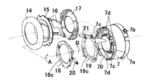
図3、図4は本実施例におけるカメラのバリア機構の展開斜視図である。図3において、14はレンズ鏡筒ユニット2の外観面を形成する外観カバー、15は外観カバー14と共にレンズ鏡筒ユニット2の前面を覆い、カメラの外観面を形成するバリアカバーである。図3及び図4において、16は電源ON・OFFの動作(レンズ鏡筒ユニット2の動作)に従って撮影レンズ(第1レンズユニット70)の前面を開閉するバリア部材であり、後述する駆動部材18と係合するピン部16aを備えている。また、バリア部材16の回転中心はレンズ保持部材7に対して基準軸7cの位置に設けられている。このためバリア部材16はレンズ保持部材7の基準軸(回転中心)7cに取り付けられ、これを中心に回転する。
3 and 4 are developed perspective views of the barrier mechanism of the camera in this embodiment. In FIG. 3, 14 is an external cover that forms the external surface of the
17はバリア部材16が撮影レンズ(第1レンズユニット70)に触れないように光軸方向の位置を規制するバリア仕切り板、18はバリア仕切り板17よりも結像面側に配置され、バリア部材16を駆動する駆動部材(第2の部材)である。駆動部材18にはバリア部材16(ピン部16a)を駆動するためのU字型の溝部18aが備えられている。
また、19はレンズ保持部材7の動作を回転運動に変換する差動部材(第3の部材)であり、ベース部材10に備えられるカム部10aと当接するカム部19aが設けられている。駆動部材18と差動部材19間には駆動部材18を回転方向Aに付勢する付勢ばね20が設けられており、レンズ保持部材7と差動部材19間にはB方向に差動部材19をレンズ保持部材7に対して常に付勢するように付勢ばね21が設けられている。このように、付勢ばね20によって駆動部材18と差動部材19は一体で回転することが可能となる。また、付勢ばね21は、バリア部材16を開き方向へ付勢するためのばねである。
Further, 19 is a differential member that converts operation of the
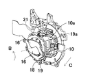
次に、本実施例におけるカメラのバリア機構とレンズ保持部材7との動作について図5及び図6を用いて説明する。図5にはベース部材10、バリア部材16、駆動部材18、差動部材19、付勢ばね21を示しており、カメラの電源OFF時の状態である。
Next, the operation of the camera barrier mechanism and the
図5においてカメラの電源がONされると、レンズ鏡筒ユニット2は光軸方向Cに繰り出す。そして、レンズ鏡筒ユニット2が繰り出すことにより、差動部材19のカム部19aがベース部材10のカム部10aから離れる方向(光軸方向)に移動するとともに、付勢ばね21の開き力によって差動部材19は図中B方向に回転する。差動部材19と駆動部材18は付勢ばね20によって一体に回転するため駆動部材18も図中B方向に回転する。
In FIG. 5, when the camera is turned on, the
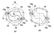
次にバリア部材16と駆動部材18との関係を説明する。なお、図6において、バリア部材16のピン部16aと駆動部材18のU字型溝部18aを説明するために、バリア部材16の一部を切り欠いて図示している。
Next, the relationship between the
図6(a)はカメラの電源OFF時の図であり、図5と同一の状態である。上述のように差動部材19が図中B方向に回転する時、駆動部材18も図中B方向に回転する。駆動部材18の回転に伴うU字型溝部18aの移動によって、バリア部材16はU字型溝部18aと係合するピン部16aを介して駆動部材18の回転力を受けて図中D方向に回転する。レンズ鏡筒ユニット2の繰り出しが終わるとバリア部材16と駆動部材18は図6(b)の状態になり、バリア部材16の開き動作が終了してカメラが撮影可能状態となる。
FIG. 6A is a diagram when the camera is turned off, which is the same state as FIG. As described above, when the
また、カメラの電源OFF時には、バリア部材16は閉じ方向に、すなわち上記開き方向の動作とは逆方向の動作をする。具体的には、レンズ保持部材7(第1レンズユニット70)がワイド端のとき、差動部材19はカムによって回動するが、駆動部材18は回転せず、レンズ保持部材7が沈胴したときに初めて差動部材19と駆動部材18が一体となって回転してバリア部材16が閉じ方向に動作する。
When the camera is turned off, the
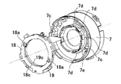
次に、差動部材19と駆動部材18の組み立てについて図7を用いて説明をする。図7において駆動部材18に設けられている爪部18bと差動部材19に設けられている引掛け部19bの位相を合わせて、図中E方向に回転させる。これによって駆動部材18と差動部材19は組み立て時には回転可能で、且つ光軸方向には位置が規制されるようになる。この時、駆動部材18と差動部材19はガタを持った状態で組み込まれる。
Next, assembly of the
その後、付勢ばね20を駆動部材18と差動部材19間にかけることによって、駆動部材18は差動部材19を基準に図中F方向に常に付勢されつつ一体となる。このため、駆動部材18と差動部材19は簡単な構成でユニット化することができる。
After that, by applying the biasing
そして、一体となった差動部材19と駆動部材18をレンズ保持部材7(レンズ鏡筒ユニット2)に組み付けるが、両者はユニット化されているため、レンズ保持部材7に組み付ける時にレンズ近傍での作業が1回で終わる。そして、余計な作業を必要としないため、不用意にレンズに傷をつけてしまうこと等が防止される。
The integrated
より具体的には、ユニット化された駆動部材18と差動部材19はレンズ保持部材7に対して図8に示すように構成される。同図においてレンズ保持部材7の係合部7dと駆動部材18の内周係合部18cが嵌合し、また、レンズ保持部材7の係合部7dと差動部材19の内周係合部19cが嵌合している。
More specifically, the
このため、駆動部材18(及び差動部材19)の回転中心位置が係合部(中心決め部)7dによって位置決めされ、駆動部材18と差動部材19はレンズ鏡筒ユニット2の光軸中心に対して偏芯することなく回動することができる。
Therefore, the rotational center position of the drive member 18 (and the differential member 19) is positioned by the engaging portion (centering portion) 7d, and the
すなわち、本実施例では、駆動部材18、差動部材19がレンズ保持部材7の係合部7dに位置決めされて該レンズ保持部材7を基準に回動し、また、バリア部材16はレンズ保持部材7に設けられた回転中心7cを基準に回転する。このため、レンズバリア装置は全てレンズ保持部材7を基準に動作する機構となり、余計なガタ等、すなわち駆動部材18等が偏芯せずに動作することが可能となる。したがって、簡略化された構成で、かつ安定動作が可能なレンズバリア装置を提供することが可能になる。
That is, in this embodiment, the driving
また、駆動部材18と差動部材19は簡単な構成で一体(ユニット)化しているので組み立て時の撮影レンズの近傍での作業を少なくすることができ、撮影レンズを傷つける等の問題も回避され、簡単に組み立てることができる。
Further, since the
なお、レンズ保持部材7の係合部7dは、円筒部7eの外周面における周方向の複数箇所に凸面状に形成されている。これは、円筒部7eの外周面に駆動部材18及び差動部材19をほとんどガタなく係合(嵌合)させると、両部材の当接(摺動)する面積が大きくなり大きな摩擦が生じ、該摩擦によって駆動部材18と差動部材19の動作が円滑に行われ難くなるためであり、本実施例のように係合部7dを凸面状とすることで内周係合部18c、19cとの摺動における摩擦を低減させ、円滑な動作が可能となる。
The engaging
1 カメラ本体
2 レンズ鏡筒ユニット
7 レンズ保持部材
7d 係合部(中心決め部)
16 バリア部材
18 駆動部材
19 差動部材
DESCRIPTION OF
16
Claims (3)
レンズ鏡筒を構成するレンズ保持部材と、
前記レンズ保持部材に対して回動可能に保持され、この回動によってレンズの光路を遮光可能なバリア部材と、
前記レンズ保持部材に対して回転することにより前記バリア部材を回動させる駆動部材と、
前記駆動部材との間に付勢部材が設けられた部材であって、前記レンズ保持部材の移動に応じて前記第1のカム部と接して回転力を伝達する第2のカム部を有していて当該回転力により前記駆動部材を回転させる差動部材とを備え、
前記差動部材と前記駆動部材とは、互いに有する係合部により係合して前記付勢部材により付勢することでガタを持ってユニット化される部材であって、当該ユニット化された前記差動部材及び前記駆動部材を前記レンズ保持部材に組み付けることによって、前記レンズ保持部材に対して前記差動部材及び前記駆動部材が位置決めされていることを特徴とするカメラ。 A base member having a first cam portion ;
A lens holding member constituting the lens barrel;
A barrier member that is rotatably held with respect to the lens holding member, and is capable of blocking the optical path of the lens by this rotation;
A drive member that rotates the barrier member by rotating with respect to the lens holding member ;
A biasing member is provided between the driving member and a second cam portion that contacts the first cam portion and transmits a rotational force in accordance with the movement of the lens holding member. And a differential member that rotates the drive member by the rotational force,
The differential member and the driving member are members that are united with a backlash by being engaged with each other by an engaging portion and being urged by the urging member. A camera, wherein the differential member and the drive member are positioned with respect to the lens holding member by assembling the differential member and the drive member to the lens holding member .
The camera according to claim 1 or 2, characterized in that an imaging device for photoelectrically converting an object image formed by light having passed through the lens barrel.
Priority Applications (1)
| Application Number | Priority Date | Filing Date | Title |
|---|---|---|---|
| JP2004281582A JP4474253B2 (en) | 2004-09-28 | 2004-09-28 | camera |
Applications Claiming Priority (1)
| Application Number | Priority Date | Filing Date | Title |
|---|---|---|---|
| JP2004281582A JP4474253B2 (en) | 2004-09-28 | 2004-09-28 | camera |
Publications (3)
| Publication Number | Publication Date |
|---|---|
| JP2006098486A JP2006098486A (en) | 2006-04-13 |
| JP2006098486A5 JP2006098486A5 (en) | 2007-11-29 |
| JP4474253B2 true JP4474253B2 (en) | 2010-06-02 |
Family
ID=36238403
Family Applications (1)
| Application Number | Title | Priority Date | Filing Date |
|---|---|---|---|
| JP2004281582A Expired - Fee Related JP4474253B2 (en) | 2004-09-28 | 2004-09-28 | camera |
Country Status (1)
| Country | Link |
|---|---|
| JP (1) | JP4474253B2 (en) |
Families Citing this family (5)
| Publication number | Priority date | Publication date | Assignee | Title |
|---|---|---|---|---|
| JP4574633B2 (en) * | 2007-02-14 | 2010-11-04 | キヤノン株式会社 | Imaging device |
| JP4958804B2 (en) | 2008-01-22 | 2012-06-20 | キヤノン株式会社 | Optical lens barrel and imaging device |
| JP2010151950A (en) | 2008-12-24 | 2010-07-08 | Canon Inc | Imaging apparatus and lens device |
| JP5328335B2 (en) | 2008-12-24 | 2013-10-30 | キヤノン株式会社 | Imaging device and lens device |
| JP2010271492A (en) * | 2009-05-20 | 2010-12-02 | Olympus Imaging Corp | Barrier device |
-
2004
- 2004-09-28 JP JP2004281582A patent/JP4474253B2/en not_active Expired - Fee Related
Also Published As
| Publication number | Publication date |
|---|---|
| JP2006098486A (en) | 2006-04-13 |
Similar Documents
| Publication | Publication Date | Title |
|---|---|---|
| JP4939074B2 (en) | Imaging device | |
| JP5383347B2 (en) | Lens barrel and imaging device | |
| JP2007248608A (en) | Lens barrel and camera | |
| JP2006301290A (en) | Lens barrel | |
| JP4590163B2 (en) | camera | |
| JP4474253B2 (en) | camera | |
| JP2023088071A (en) | camera device | |
| JP2007033961A (en) | Lens driving apparatus | |
| JP2006098486A5 (en) | ||
| JP4338954B2 (en) | camera | |
| JP2009265517A (en) | Lens device and imaging apparatus | |
| JP4429714B2 (en) | Lens barrel drive mechanism | |
| JP2003315892A (en) | Lens barrier unit | |
| JP2005308810A (en) | Lens barrel and imaging apparatus | |
| JP2011123107A (en) | Barrier mechanism and photographing apparatus | |
| JP4472389B2 (en) | Zoom lens barrel | |
| JP2004258167A (en) | Camera | |
| JP2005062342A (en) | Lens-barrel driving mechanism | |
| JP4589816B2 (en) | Lens barrel drive mechanism | |
| JP6007630B2 (en) | Lens barrel and optical device | |
| JP5037884B2 (en) | Barrier device and imaging device | |
| JP5713711B2 (en) | Lens barrel | |
| JP2013029599A (en) | Lens barrel and imaging device with the same | |
| JP2004287260A (en) | Camera | |
| JP6083983B2 (en) | Lens barrel and imaging device having the same |
Legal Events
| Date | Code | Title | Description |
|---|---|---|---|
| A621 | Written request for application examination |
Free format text: JAPANESE INTERMEDIATE CODE: A621 Effective date: 20070928 |
|
| A521 | Request for written amendment filed |
Free format text: JAPANESE INTERMEDIATE CODE: A523 Effective date: 20071012 |
|
| RD03 | Notification of appointment of power of attorney |
Free format text: JAPANESE INTERMEDIATE CODE: A7423 Effective date: 20081010 |
|
| RD05 | Notification of revocation of power of attorney |
Free format text: JAPANESE INTERMEDIATE CODE: A7425 Effective date: 20081201 |
|
| A977 | Report on retrieval |
Free format text: JAPANESE INTERMEDIATE CODE: A971007 Effective date: 20091014 |
|
| A131 | Notification of reasons for refusal |
Free format text: JAPANESE INTERMEDIATE CODE: A131 Effective date: 20091027 |
|
| A521 | Request for written amendment filed |
Free format text: JAPANESE INTERMEDIATE CODE: A523 Effective date: 20091228 |
|
| TRDD | Decision of grant or rejection written | ||
| A01 | Written decision to grant a patent or to grant a registration (utility model) |
Free format text: JAPANESE INTERMEDIATE CODE: A01 Effective date: 20100302 |
|
| A01 | Written decision to grant a patent or to grant a registration (utility model) |
Free format text: JAPANESE INTERMEDIATE CODE: A01 |
|
| A61 | First payment of annual fees (during grant procedure) |
Free format text: JAPANESE INTERMEDIATE CODE: A61 Effective date: 20100308 |
|
| FPAY | Renewal fee payment (event date is renewal date of database) |
Free format text: PAYMENT UNTIL: 20130312 Year of fee payment: 3 |
|
| R150 | Certificate of patent or registration of utility model |
Free format text: JAPANESE INTERMEDIATE CODE: R150 |
|
| FPAY | Renewal fee payment (event date is renewal date of database) |
Free format text: PAYMENT UNTIL: 20140312 Year of fee payment: 4 |
|
| LAPS | Cancellation because of no payment of annual fees |