JP4471547B2 - Web winding start device and method - Google Patents
Web winding start device and method Download PDFInfo
- Publication number
- JP4471547B2 JP4471547B2 JP2001503370A JP2001503370A JP4471547B2 JP 4471547 B2 JP4471547 B2 JP 4471547B2 JP 2001503370 A JP2001503370 A JP 2001503370A JP 2001503370 A JP2001503370 A JP 2001503370A JP 4471547 B2 JP4471547 B2 JP 4471547B2
- Authority
- JP
- Japan
- Prior art keywords
- web
- roll
- pantograph frame
- winding roll
- cutting
- Prior art date
- Legal status (The legal status is an assumption and is not a legal conclusion. Google has not performed a legal analysis and makes no representation as to the accuracy of the status listed.)
- Expired - Fee Related
Links
Images


Classifications
-
- B—PERFORMING OPERATIONS; TRANSPORTING
- B65—CONVEYING; PACKING; STORING; HANDLING THIN OR FILAMENTARY MATERIAL
- B65H—HANDLING THIN OR FILAMENTARY MATERIAL, e.g. SHEETS, WEBS, CABLES
- B65H19/00—Changing the web roll
- B65H19/22—Changing the web roll in winding mechanisms or in connection with winding operations
- B65H19/28—Attaching the leading end of the web to the replacement web-roll core or spindle
-
- B—PERFORMING OPERATIONS; TRANSPORTING
- B65—CONVEYING; PACKING; STORING; HANDLING THIN OR FILAMENTARY MATERIAL
- B65H—HANDLING THIN OR FILAMENTARY MATERIAL, e.g. SHEETS, WEBS, CABLES
- B65H19/00—Changing the web roll
- B65H19/22—Changing the web roll in winding mechanisms or in connection with winding operations
- B65H19/26—Cutting-off the web running to the wound web roll
Abstract
Description
【0001】
(技術分野)
本発明は、装置とともに使用されるのに適したダブル・パンタグラフ・フレームだけでなく、ロールのウェブへの巻き取りを開始するための装置及び方法に関する。
【0002】
(発明の背景)
一般に、薄いポリエステルフィルム又は他のシート材料のようなウェブは、連続工程で製造され、最終製品は、貯蔵及び輸送のためにロールに巻き取られる。
【0003】
しかしながら、連続製造工程は、ウェブの破断によりしばしば中断され、ロール巻き取りが再スタートしなければならない。ひとつの可能性は、巻き取りユニットから上流で製造を停止することである。しかしながら、これは、明白に避けられるべきである。製造が連続されている場合には、ロールに巻き取られないウェブの部分が処理されなければならない。例えば、破断後巻き取りユニットを再スタートするひとつの可能性は、破断による異常が克服されるまで、補助ロールにある程度の量のウェブを巻き取るか、又はその量のウェブをシュート(樋)に誘導し、その後、制御された方法でウェブを切断して後、補助ロール又はシュートから、基準ロールでの巻き取りを継続することである。しかしながら、補助ロール又はシュートから基準ロールへ切換えること及び制御された切断は、複雑であり、時間を消費し、したがって高価である。
【0004】
小さいサイズのいくつかの基準ロールが、巻き取り前に搬送方向に沿ってウェブを分割することにより同じ大きなウェブから同時に巻き取られている場合、問題は、さらに一層厳しい。今まで、破損がロールのたった一つにしか作用しなかった場合でさえも全てのロールの巻き取りを停止することが必要であった。結果として、作業負荷が追加され、製造コストが高くなる。
【0005】
ミクロンサイズの厚さで1000m/minまで高速製造される(超)薄状フィルムにとって、問題は、深刻である。一つの解決は、ウェブを巻き取りユニットに転送するようにウェブに空気を送風することである。この場合、空気送風は、ウェブが2つのロールのニップ部分近傍に到来し、巻き取りの開始ができるように、制御される。この操作方法は、明白な障害、すなわち、フィルムを破壊する方法の粗っぽさと適正な巻き取りを達成するために適正な条件を適用する困難さとを欠点として持つ。
【0006】
したがって、高速での(超)薄状フィルムの巻き取りの(再)開始ができる装置及び方法の必要性がある。
米国特許第2942796号明細書は、巻き取りロールにウェブの巻き取りを開始する装置を開示している。該装置は、ウェブの搬送路内に移動することによってロールの外周部分にウェブを張り付ける弧状フィンガーを有する回転可能なアームを有している。該アームは、さらに、ロール張り付け後ウェブを切断する、弧状フィンガー近傍に配置されている固定されたナイフを有している。
ドイツ特許公開公報第3033765号は、巻き取りロールにウェブの巻き取りを開始する2つの装置を開示している。装置は、方向転換ロールが取り付けられている回転可能なアームを有している。該方向転換ロールは、アームがウェブにむけて回転すると、ウェブに接触し、ウェブをロール外周の一部の周りに張り付ける。装置は、また、回転可能なアームから又はアームにそれぞれ独立して取り付けられている、ウェブを切断するナイフを備えている。
ドイツ特許公開公報第3239922号は、巻き取りロールにウェブの巻き取りを開始する2つの装置を開示している。装置は、ロールが取り付けられ、その間をウェブが通過する回転可能なアームを有している。アームの回転は、ウェブを巻き取りロールに接触状態にする。第2装置は、第1アームに回転可能に取り付けられている第2アームを有している。該第2アームは、ウェブに接触し、巻き取りロール外周の一部にウェブを張り付けるロールを有している。
【0007】
(発明の概要)
本発明の目的は、巻き取りロールへのウェブの巻き取りを開始する装置及び方法を提供し、1又はいくつかの基準ロールに対する巻き取りの容易なかつ速い開始/再開始を可能とし、それによって、作業負荷及び製造コストを減少させることにある。
【0008】
この目的は、請求項26に係るダブル・パンタグラフ・フレームだけでなく、請求項1と24に係る装置及び請求項29と37に係る方法により達成される。好ましい実施形態が従属項に限定されている。
【0009】
上述された装置及び方法は、第2駆動ロールから第1巻き取りロールへの容易なかつ速い切換を可能とする利点を有する。第2駆動ロールが補助ロールであり、第1巻き取りロールが最終製品の貯蔵用ロールである場合、本発明は貯蔵用巻き取りロールへの巻き取りの単純かつ速い開始が可能である。
【0010】
(発明の詳細な説明)
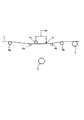
図1a−1hは、1枚のウェブに関する本発明の装置を示し、図2は、3枚のウェブ用装置を示している。
【0011】
図1aは、1枚のウェブ用の本発明に係る装置を示す。ポリエステルフィルムのようなウェブ1は、矢印Fにより表わされる搬送方向から到達する。図1aにおいて、装置は、開始時点にある。すなわち、ウェブが、巻き取り速度w1で、駆動され、又は第2ロール2に巻き取られている。ウェブ1のこの部分が、ロール2に巻き取られているか、又は、ロール2が、ウェブ1をシュート(不図示)に誘導する駆動ロールであるかいずれであってもよい。ロール2は、単純に吸引手段を有するシュートに置き換えられてもよい。第2ロールにウェブ1の駆動を開始するために、例えば、リーダーシステム、ウェブ輸送テーブル、又は吸引路として公知の何らかの手段を使用することができる。それは手動で開始されてもよい。例えどんな機能が実行されても、第2ロール2は、以下、第2駆動ロールとして称される。前記第2ロールが、唯一の2次的手段であり得る例であることが理解される。実際は、シュート又はチョッパーに連結される吸引手段もまた第2駆動手段として使用される。以下の説明は、第2駆動ロール2に関してなされる。
【0012】
図1aにおいて、第1巻き取りロール3は、第2ロールの上流で、ウェブ1の下に配置されている。切換手段4a、4bは、やはり第2ロールの上流でウェブ1の上に配置されている。切換手段4a、4b及び第1巻き取りロール3は、ウェブに実質的に直交する方向にしたがって整列されている。別の方向、横軸は、固有である。切換手段は、図1aにおいて、待機位置にある。
【0013】
切断手段5は、巻き取りロール3の近傍に配置されているか、切換手段4a、4bとグループ化されているかどちらでもよい。図1aは、切換手段4a、4bと切断手段5とがグループ化されている装置を示している。切断手段5は、1ストロークでウェブ1の横断方向の切断を可能とするためにウェブ1と同じ幅広さであることが好ましい。しかしながら、ウェブ1と同じ幅広さである代わりに、切断手段5は、細く横断方向に移動可能であってもよい。これにより、斜め切断を生ずる。切断要素は、直線状又は鋸歯状の空中で切断する刃物、環状刃、剪断ナイフ、レーザー手段、水噴射手段・・・、どのようなタイプであってもよい。
【0014】
切換手段4a、4bは、移動経路が搬送方向Fに交差するように、矢印Gで示されるように横断方向に沿って移動可能である。切換手段は、方向転換手段4bと連行手段4aとを備えている。方向転換手段4bは、ロールであり、アイドルロールであることが好ましい。連行手段4aは、移動キャリッジとして示されている。切換手段を作動させるのに必要な駆動手段は図示されていない。これらの手段は、ギア、スクリュなどを介してその動きを伝えるモータを備えていてもよい。切断手段5は、方向転換手段4bに対して下流に配置されている。示されている実施形態において、切断手段5は、さらに、ウェブが損傷なしにスライドすることができるスライディング手段を備えている。切断手段5の切断要素(すなわち、幅広い鋸歯状刃物)は、(ウェブの望ましくない切断を避けるために)伸縮自在であり、要求されたときに稼動される。切断手段5は、(切断要素が引き込められているとき)また、ロール4bと補完しあって(前記スライディング手段を介して)方向転換手段として作用する。このことは、下記図3に関連して明白である。
【0015】
一対の支持ロール6a及び6b(アイドルロールタイプのものが好ましい)が、ウェブの下で、切換手段4a、4b及び第1巻き取りロール3に対して左右に置かれている。さらなる支持ロール8a、8bが、支持ロール6a、6より高く配置されていてもよい。前記支持ロール6a、6bの作用は、第1巻き取りロール3に巻取りを開始する間、すなわち、切換手段が操作中である時、ウェブ1の搬送を支持することである。左側にある支持ロール6a、8aは、その巻取りが第1巻き取りロール3で開始された後、ウェブ1の搬送を支持することを継続している。大体において、ウェブ1は、公知の手段及び方法に従って、装置内に搬送される。
【0016】
本発明に係る装置の操作方法は、図1a−1fに示されている。
【0017】
すでに説明したように、図1aは、切換手段4a、4bがウェブ1の搬送路を横断していない待機位置にある状態を示している。ウェブ1の巻き取りは、所定の回転速度w1で第2ロールで進行している。
【0018】
図1bにおいて、切換手段は、切断手段5(その切断要素は、既に述べられたようにウェブを切断することを避けるべく後退位置にある)と同様に方向転換ロール4bとともに下降され、搬送されているウェブ1に接触し、ウェブを下方位置に連行する。ウェブ1は、支持ロール8a、8bに接触した後、支持ロール6a、6bに接触状態にされる。切換手段の下降処置のステップは、ウェブの搬送路の引き伸ばしを伴い、したがって、第2ロール2の回転速度は、ウェブ1の張力が好ましくは実質的に一定を維持されるように、w1より低い速度w2(w2<w1)に減少される。
【0019】
図1cにおいて、切換手段は、その最低位置にある。したがって、ウェブ1がループを形成している。切換手段が最終的にこの最低端位置に達すると、第2ロールの回転速度は、w1に等しい速度w3に回復する。この位置で、方向転換ロール4bが、第1巻き取りロール3に(ウェブ1を介して)接触することが好ましい。したがって、ウェブ1をロール3上に正しく横たえ、ウェブ1とロール3の間の空気を追い出す。ウェブ1は、方向転換ロール4bから該方向転換ロール4bに対してロール3の反対側に(ロール3と接触することなく)好ましくは配置されている切断手段5までの巻き取りロール3の上部分を覆う。方向転換ロール4b及び切断手段5は、ウェブ1が巻き取りロール3外周の相当部分、好ましくはその半周を覆わせるように、巻き取りロール3の両側に配置されていることが好ましい。ウェブ1がW字状を形成し、中間位置が、巻き取りロール3の頂部にあり、最低位置が方向転換ロール4b及び切断手段5のスライディング手段の底部にあることが理解される。また、巻き取りロール3が、ロール3がウェブ1に接触される前に、(ウェブ1が移動する方向と同じ方向に)固有の回転速度を与えられ、したがって、前記ウェブを切断又は破壊することが防止されることが理解される。
【0020】
切換手段が図1cに示されるように最低位置にある時はいつも、切断手段5の切断要素は、図1dに示されるように、作動する。すなわち、切断刃がウェブ1と接触状態になる。したがって、ウェブ1は、切断され、巻き取りロール3に巻き取らさせられる。その後、切断要素は、第1巻き取りロール3の巻き取りの正常な開始を妨げないために引き込まされる。切断操作中、(その切断要素を含む)切断手段5は、第1巻き取りロール3それ自体(又は、該ロール3に既に巻き取られているウェブ)と接触状態に入らないことが好ましい。ロール3の巻き取り開始は、ウェブ1が既に前記ロールの外周の一部を覆っており、上述した空気排除(さらに、静電気効果のような他の手段又は水噴霧が使用されること)のためにロールに密着した状態にあるという事実のために自動的に達成される。ウェブ1は、図に示されるように、第1巻き取りロール3の近傍、より好ましくはロール3から0、1−20mmの位置で切断されることが好ましい。したがって、このことが、ウェブ1の自由端が飛び、ロール3の巻き取りが妨げられたり、あるいはウェブ1が巻き取られるはずのロール3上でしわくちゃにされることが最大限避けられるであろう。切断手段5が、その直径であれ、ロールに既に巻き取られているウェブの量であれ、巻き取りロール3の本質的に同一の距離で維持されることが好ましい。いったんウェブ1が切断手段5により切断されると、第2ロール2は、回転を停止することができる。
【0021】
第2ロール2と第1ロール3の実際の回転速度は(関連するとすれば、他のロールの回転速度と同様)、切換手段4a、4bの降下及び第2ロールから第1ロールへのウェブ1の切換中にウェブ1の何らかの伸ばし過ぎの可能性を避けるように、トルク制御手段(図示されていないがそれ自体良く知られている)により制御される。例えば、一定トルク、すなわちウェブ1の一定張力を得るために、第2ロール2を駆動するのに定電流のD.C.(直流)モータを使用することが可能である。
【0022】
図1eにおいて、切換手段は、待機位置に戻らされる。
【0023】
さて、ウェブ1が工程のある段階で破れたとすると、この時、ロール3の巻き取りは、停止され、ウェブ1は再び第2ロール2に巻き取られる。その後、上記されたスレッドアップ(thread up)方法が直ちに繰り返される。
【0024】
製造装置から説明されている装置にウェブ1を最初に搬送する手段が示されていないが、これらの手段はそれ自体周知である。また、巻き取りロール3は、例えば、望むのであれば最初のロールと取り替えるために(例えば、一杯に巻き取られた時や、開始ロールから基準ロールに切換えるため)、回転アーム、を介して別の巻き取りロールと従来のように対にされていてもよい。
【0025】
図1fは、図1cに対応する段階の別の実施形態を示している。この場合においては、切換手段は、巻き取りロール3の両側に接触する2つの方向転換ロール4b、4’bを備えている。切断手段は、巻き取りロール3と方向転換ロールのうちの一方の近傍に配置されている。この場合においては、切断手段5は、切換手段4a、4bと対にされてはいないが、巻き取りロール3の領域に据え付けられている。
【0026】
上記の実施形態は、既にロールに巻き取られているウェブを支持することに加えて、空のロールに巻取りを開始することが可能であることが理解される。
【0027】
本発明の装置は、特に、より小さいウェブに分割されたウェブの巻き取りに適している。図2は、分割されたウェブ1(すなわち、ウェブ1a、1b、1c)をいくつかの対応する第1巻き取りロール3(最初のもののみが図示されている)上に平行に巻き取る、本発明に係るいくつかの巻き取り装置を示す斜視図である。さらに、該装置は、各ウェブ1a、1b、1cを適正な速度で駆動する第2駆動手段を備えている。例えば、図2に示されている第2駆動手段は、各区分7a、7b、7cがそれぞれのシュート(図示されていない)で自身の速度で駆動されているそれぞれのウェブに対応しているアイドル分割ロール(2)を備えている。もちろん、当業者は、この目的を満足することができる第2駆動手段の別のタイプを予測し得る。
【0028】
装置は、第2ロール2に巻き取られているウェブ1b、1c及び図1cに記載されているような段階に関わっているウェブ1a(前の巻き取りロールに対応する)で表わされている。ウェブ1aに関してのみ、要素8a、6a、6b、8b(ウェブを搬送するための)、巻き取りロール3、方向転換ロール4b及び切断手段5が表わされている。
【0029】
さて、ウェブ1a、1b及び1cが第2ロール2、すなわち、区分7a、7b及び7cに巻き取られているとすると、問題のウェブ1a用切換手段の降下が開始される時、回転速度(wa)は、好ましくはウェブ1a、1b、1cのそれぞれの一定張力を維持するために、隣り合う区分の回転速度(wb)とは異なる。また、破損がウェブ1a、1b、1cのうちの1つに生じると、分割ロール2の対応する区分7a、7b、7cを使用している対応する装置のみに対して再開始工程が実行される。一方、他の装置の巻き取りは、中断されずに継続している。したがって、他の巻き取りロールは、実行しつづけ、ウェブの損失が最小限にされる。
【0030】
図3は、好ましい切換手段の拡大図を示している。該切換手段は、ダブル・パンタグラフ・フレームを備えている。切断手段5は、ウェブ1が安全にスライドできるスライディング面5a、5b、5cを備えている。一方、切断要素5d、好ましくは、刃は、前記面の間に引き込まされている(刃5は、表示されていない)。方向転換用アイドラ−ロール4bと切断手段5とを運ぶ連行手段4aは、以下の要素、水平部分11aに2つのボールベアリング12aと12bが固定されている移動可能なT字形支持体11を備えている。支持体11の垂直部分には、スライド可能にキャリッジ13が設けられている。該キャリッジは、2対のボールベアリング14a、14b、15a及び15bを備えている。第1パンタグラフ(左側のもの)は、(ボールベアリング14a、15aをそれぞれ介して)キャリッジ13及び(同様にボールベアリングを介して)アーム16aに連接される2つの平行なアーム17a、18aにより得られる。対称的に、第2パンタグラフ(右側のもの)は、(ボールベアリング14b、15bをそれぞれ介して)キャリッジ13及び(同様にボールベアリングを介して)アーム16bに連接される2つの平行なアーム17b、18bにより得られる。アーム16aと16bは、それぞれ方向転換ロール4b及び切断手段5を支える。該切断手段5は、巻き取りロール3と切断手段5との間に定められた隙間を(好ましくは、上記された範囲0.1−20mmに)確保するために、アーム16bに対して方向Fに沿って調整可能である。アーム19aは、(ボールベアリング12aを介して)支持体11及びアーム18aに連接されている。対称的に、アーム19bは、(ボールベアリング12bを介して)支持体11及びアーム18bに連接されている。支持体11に対してキャリッジ13を平行移動させることにより、方向転換ロール4bと切断手段5は、お互いに対して対称的に移動させられる。パンタグラフフレームを閉じた位置(すなわち、図3に示されるように、アーム16a、16bの最も狭くなっている位置)に後退させる、例えば、スプリングのような補足手段が設けられ得る。切換手段が第1巻き取りロール3へ降下されると、方向転換ロール4bが、(ウェブ1を介して)前記ロール3の左側に当接し、左側のパンタグラフは、ロール3の直径にしたがう範囲に開く。したがって、右側のパンタグラフが同じ程度に開き、結果として、ダブル・パンタグラフ・フレームの対称面が巻き取りロール3の回転軸を構成するので、切断手段5と巻き取りロール3との間の調整された隙間は、ロール3の直径に関係なく実質的に同一のままである。一般的に、これらの切換手段は、いろいろな直径の巻心又は巻き取りロールに適応させられ(切断後、もし切換手段が巻き取り開始後直ちに後退されなければロール3に巻き取る間直径の増加についていくことができる)、それにも拘らず、図1c及び1dに関連して述べられた好ましい特徴を実施することができる。
【0031】
図3のダブル・パンタグラフ・フレームは、また、図1fの実施形態に使用するのにも適している。この場合、第2ロール4’bが、切断手段5の代わりにアーム16bの末端部にはめ込まれる。
【0032】
本発明は、好ましい実施形態を参考にして説明された。しかしながら、本発明の範囲内で多くの変形が可能である。例えば、駆動ロールや巻き取りロールは、1又はそれ以上のロールと結合し、随意にいろいろな径を持ち得る。
【図面の簡単な説明】
【図1a】 本発明に係る装置の概略側面図であり、該装置の操作を説明するためのものである。
【図1b】 本発明に係る装置の概略側面図であり、該装置の操作を説明するためのものである。
【図1c】 本発明に係る装置の概略側面図であり、該装置の操作を説明するためのものである。
【図1d】 本発明に係る装置の概略側面図であり、該装置の操作を説明するためのものである。
【図1e】 本発明に係る装置の概略側面図であり、該装置の操作を説明するためのものである。
【図1f】 本発明に係る装置の概略側面図であり、該装置の操作を説明するためのものである。
【図2】 3つのウェブ用に作動する本発明に係る装置の概略斜視図である。
【図3】 本発明に係る切換手段の拡大図である。[0001]
(Technical field)
The present invention relates to an apparatus and method for initiating winding of a roll onto a web as well as a double pantograph frame suitable for use with the apparatus.
[0002]
(Background of the Invention)
In general, a web, such as a thin polyester film or other sheet material, is manufactured in a continuous process and the final product is wound into rolls for storage and transportation.
[0003]
However, continuous production processes are often interrupted by web breaks and roll winding must be restarted. One possibility is to stop production upstream from the winding unit. However, this should be explicitly avoided. If the production is continuous, the portion of the web that is not wound on the roll must be processed. For example, one possibility to restart the take-up unit after breakage is to wind up a certain amount of web on the auxiliary roll, or to chute that amount of web until the failure due to breakage is overcome. Guiding and then cutting the web in a controlled manner and then continuing with the reference roll from the auxiliary roll or chute. However, switching from the auxiliary roll or chute to the reference roll and controlled cutting is complex, time consuming and therefore expensive.
[0004]
The problem is even more severe if several small sized reference rolls are simultaneously wound from the same large web by splitting the web along the transport direction prior to winding. To date, it has been necessary to stop the winding of all rolls even if the breakage has affected only one of the rolls. As a result, workload is added and manufacturing costs are increased.
[0005]
The problem is acute for (ultra) thin films that are manufactured at high speeds up to 1000 m / min with micron thickness. One solution is to blow air through the web to transfer the web to the take-up unit. In this case, the air blowing is controlled so that the web arrives in the vicinity of the nip portion of the two rolls and winding can be started. This method of operation has the disadvantage of obvious obstacles: the roughness of the method of breaking the film and the difficulty of applying the correct conditions to achieve proper winding.
[0006]
Accordingly, there is a need for an apparatus and method that can initiate (re) starting the winding of (ultra) thin film at high speed.
U.S. Pat. No. 2,942,792 discloses an apparatus for initiating web winding on a winding roll. The apparatus has a rotatable arm with arcuate fingers that stick the web to the outer periphery of the roll by moving into the web transport path. The arm further has a fixed knife positioned near the arcuate fingers that cuts the web after roll application.
German Offenlegungsschrift 3033765 discloses two devices for initiating web winding on a winding roll. The device has a rotatable arm to which a turning roll is attached. The diverting roll contacts the web as the arm rotates toward the web and sticks the web around a portion of the roll periphery. The apparatus also includes a knife for cutting the web, each attached independently from or to the rotatable arm.
German Offenlegungsschrift 3239922 discloses two devices for initiating web winding on a winding roll. The apparatus has a rotatable arm to which the roll is attached and between which the web passes. The rotation of the arm brings the web into contact with the take-up roll. The second device has a second arm rotatably attached to the first arm. The second arm has a roll that contacts the web and attaches the web to a part of the outer periphery of the take-up roll.
[0007]
(Summary of Invention)
It is an object of the present invention to provide an apparatus and method for initiating winding of a web onto a take-up roll, allowing easy and fast start / restart of take-up for one or several reference rolls, thereby To reduce workload and manufacturing costs.
[0008]
This object is achieved not only by the double pantograph frame according to claim 26 but also by the device according to claims 1 and 24 and the method according to claims 29 and 37. Preferred embodiments are limited to the dependent claims.
[0009]
The apparatus and method described above have the advantage of allowing easy and fast switching from the second drive roll to the first take-up roll. When the second drive roll is an auxiliary roll and the first take-up roll is the final product storage roll, the present invention allows a simple and fast start of winding onto the storage take-up roll.
[0010]
(Detailed description of the invention)
1a-1h show the device of the present invention for a single web, and FIG. 2 shows a device for three webs.
[0011]
FIG. 1a shows a device according to the invention for a single web. A web 1 such as a polyester film arrives from the conveying direction represented by arrow F. In FIG. 1a, the device is at the start. That is, the web is driven at the winding speed w <b> 1 or is wound on the
[0012]
In FIG. 1a, the first take-
[0013]
The cutting means 5 may be arranged in the vicinity of the take-
[0014]
The switching means 4a and 4b are movable along the transverse direction as indicated by the arrow G so that the movement route intersects the transport direction F. The switching means includes direction changing means 4b and entraining means 4a. The
[0015]
A pair of support rolls 6a and 6b (preferably of the idle roll type) are placed on the left and right with respect to the switching means 4a and 4b and the first winding
[0016]
A method of operating the device according to the invention is shown in FIGS. 1a-1f.
[0017]
As already explained, FIG. 1 a shows a state in which the switching means 4 a, 4 b are in a standby position where they do not cross the transport path of the web 1. Winding of the web 1 proceeds with the second roll at a predetermined rotational speed w1.
[0018]
In FIG. 1b, the switching means is lowered and conveyed with the turning
[0019]
In FIG. 1c, the switching means is in its lowest position. Therefore, the web 1 forms a loop. When the switching means finally reaches this lowest end position, the rotation speed of the second roll is restored to a speed w3 equal to w1. At this position, it is preferable that the
[0020]
Whenever the switching means is in the lowest position as shown in FIG. 1c, the cutting element of the cutting means 5 operates as shown in FIG. 1d. That is, the cutting blade comes into contact with the web 1. Accordingly, the web 1 is cut and wound on the winding
[0021]
The actual rotational speeds of the
[0022]
In FIG. 1e, the switching means is returned to the standby position.
[0023]
Now, assuming that the web 1 is torn at a certain stage in the process, the winding of the
[0024]
The means for initially conveying the web 1 to the apparatus described from the production apparatus are not shown, but these means are well known per se. Also, the take-
[0025]
FIG. 1f shows another embodiment of the stage corresponding to FIG. 1c. In this case, the switching means includes two
[0026]
It will be appreciated that the above embodiments can initiate winding on an empty roll in addition to supporting a web that has already been wound on a roll.
[0027]
The device according to the invention is particularly suitable for winding a web divided into smaller webs. FIG. 2 shows a book in which a divided web 1 (
[0028]
The device is represented by
[0029]
Now, assuming that the
[0030]
FIG. 3 shows an enlarged view of the preferred switching means. The switching means includes a double pantograph frame. The cutting means 5 is provided with sliding
[0031]
The double pantograph frame of FIG. 3 is also suitable for use in the embodiment of FIG. In this case, the second roll 4 ′ b is fitted into the end of the
[0032]
The invention has been described with reference to the preferred embodiments. However, many variations are possible within the scope of the present invention. For example, the drive roll and take-up roll can be combined with one or more rolls and optionally have various diameters.
[Brief description of the drawings]
FIG. 1a is a schematic side view of an apparatus according to the present invention for explaining the operation of the apparatus.
FIG. 1b is a schematic side view of an apparatus according to the present invention for explaining the operation of the apparatus.
FIG. 1c is a schematic side view of an apparatus according to the present invention for explaining the operation of the apparatus.
FIG. 1d is a schematic side view of an apparatus according to the present invention for explaining the operation of the apparatus.
FIG. 1e is a schematic side view of an apparatus according to the present invention for explaining the operation of the apparatus.
FIG. 1f is a schematic side view of an apparatus according to the present invention for explaining the operation of the apparatus.
FIG. 2 is a schematic perspective view of an apparatus according to the present invention operating for three webs.
FIG. 3 is an enlarged view of switching means according to the present invention.
Claims (9)
第1巻き取りロール(3)、
ウェブ搬送路でウェブを駆動するための第2駆動手段(2)、及び
前記第2駆動手段によって前記ウェブ搬送路で駆動されているウェブ(1)を前記第1巻き取りロール(3)に切換える切換手段(4a、4b)、
を備え、
切断手段(5)は、前記切換手段(4a、4b)に取り付けられ、
前記切換手段(4a、4b)は、ウェブ(1)に接触する方向転換手段(4b、5)を備え、前記方向転換手段は、前記第2駆動手段(2)によって駆動されるウェブに対して前記第1巻き取りロール(3)の反対側に配置され、前記切換手段は、前記ウェブ搬送路と交差するように、前記ウェブ搬送路の外にある待機位置から前記第1巻き取りロール(3)に向かって移動可能であり、それによって、ウェブは、前記切断手段(5)で切断され、前記第1巻き取りロール(3)に巻き取られることになり、
前記切換手段(4a、4b)は、第1パンタグラフ・フレームの位置の変更が第2パンタグラフ・フレームの対称的な変化を引き起こすように、お互いに対称的に配置され、動作可能なように支持体(11、11a、13)により連結される前記第1パンタグラフ・フレーム(16a、17a、18a、13)及び前記第2パンタグラフ・フレーム(16b、17b、18b、13)を備えるダブル・パンタグラフ・フレームを備え、前記第1パンタグラフ・フレームのアーム(16a)は、当接手段(4b)を運び、前記第2パンタグラフ・フレームのアーム(16b)は、前記第1パンタグラフ・フレームのアーム(16a)に対称的に配置され、前記第1巻き取りロール(3)上の前記当接手段(4b)の当接が前記第1巻き取りロール(3)に対する前記切断手段(5)の位置決めを行うように前記切断手段(5)を運ぶことを特徴とする巻き取り装置。An apparatus for starting winding of at least one web (1) that arrives from a conveying direction (F) onto a roll,
First take-up roll (3),
Second driving means (2) for driving the web in the web conveyance path, and switching the web (1) driven in the web conveyance path by the second driving means to the first winding roll (3) Switching means (4a, 4b),
With
The cutting means (5) is attached to the switching means (4a, 4b),
The switching means (4a, 4b) includes direction changing means (4b, 5) that contact the web (1), and the direction changing means is for the web driven by the second driving means (2). It arrange | positions on the opposite side of the said 1st winding roll (3), and the said switching means is a said 1st winding roll (3 from the waiting position outside the said web conveyance path so that the said web conveyance path may be crossed. ), Whereby the web is cut by the cutting means (5) and wound on the first winding roll (3),
The switching means (4a, 4b) are arranged symmetrically with respect to each other and operable so that a change in the position of the first pantograph frame causes a symmetrical change in the second pantograph frame. A double pantograph frame comprising the first pantograph frame (16a, 17a, 18a, 13) and the second pantograph frame (16b, 17b, 18b, 13) connected by (11, 11a, 13) The arm (16a) of the first pantograph frame carries contact means (4b), and the arm (16b) of the second pantograph frame is symmetrical to the arm (16a) of the first pantograph frame And the contact of the contact means (4b) on the first winding roll (3) is the first winding roll. (3) said cutting means (5) winding device, wherein the carry cutting means (5) so as to position the relative.
前記キャリッジ(13)は、前記第1パンタグラフ・フレーム及び第2パンタグラフ・フレーム各々に対し1つのアームを定めており、 The carriage (13) defines one arm for each of the first pantograph frame and the second pantograph frame;
前記支持体(11、11a)は、前記第1パンタグラフ・フレーム及び第2パンタグラフ・フレームの開きの変化を連携して起させる連接アーム(19a、19b)を介して前記第1パンタグラフ・フレーム及び第2パンタグラフ・フレーム各々に連結されていることを特徴とする請求項1ないし5のいずれかに記載の装置。 The support (11, 11a) is connected to the first pantograph frame and the second pantograph frame via articulated arms (19a, 19b) that cooperatively cause changes in the opening of the first pantograph frame and the second pantograph frame. 6. An apparatus according to any one of the preceding claims, wherein the apparatus is connected to each of two pantograph frames.
Applications Claiming Priority (3)
| Application Number | Priority Date | Filing Date | Title |
|---|---|---|---|
| EP99401484A EP1061025A1 (en) | 1999-06-16 | 1999-06-16 | Apparatus and method for initiating the winding of webs |
| EP99401484.3 | 1999-06-16 | ||
| PCT/EP2000/005437 WO2000076895A1 (en) | 1999-06-16 | 2000-06-14 | Apparatus and method for initiating the winding of webs |
Publications (3)
| Publication Number | Publication Date |
|---|---|
| JP2003502244A JP2003502244A (en) | 2003-01-21 |
| JP2003502244A5 JP2003502244A5 (en) | 2007-07-19 |
| JP4471547B2 true JP4471547B2 (en) | 2010-06-02 |
Family
ID=8242012
Family Applications (1)
| Application Number | Title | Priority Date | Filing Date |
|---|---|---|---|
| JP2001503370A Expired - Fee Related JP4471547B2 (en) | 1999-06-16 | 2000-06-14 | Web winding start device and method |
Country Status (7)
| Country | Link |
|---|---|
| US (1) | US6676064B1 (en) |
| EP (2) | EP1061025A1 (en) |
| JP (1) | JP4471547B2 (en) |
| AT (1) | ATE256064T1 (en) |
| DE (1) | DE60007136T2 (en) |
| TW (1) | TW531522B (en) |
| WO (1) | WO2000076895A1 (en) |
Families Citing this family (1)
| Publication number | Priority date | Publication date | Assignee | Title |
|---|---|---|---|---|
| JP6804422B2 (en) * | 2017-10-10 | 2020-12-23 | Ckd株式会社 | Winding device |
Family Cites Families (10)
| Publication number | Priority date | Publication date | Assignee | Title |
|---|---|---|---|---|
| US2942796A (en) * | 1954-08-26 | 1960-06-28 | Monsanto Chemicals | Apparatus for winding thermoplastic film into rolls |
| US3341144A (en) * | 1965-03-23 | 1967-09-12 | Mase Tetsuro | Apparatus for winding web |
| US3796388A (en) * | 1970-07-23 | 1974-03-12 | Du Pont | Apparatus for winding a running length of thermoplastic sheeting into a series of rolls |
| FR2320886A1 (en) * | 1975-12-18 | 1977-03-11 | Agfa Gevaert | Sheet cutting and rolling machine - has pivotally mounted blade which moves across sheet to cut it diagonally as it moves |
| JPS56149941A (en) * | 1980-04-21 | 1981-11-20 | Fuji Tekkosho:Kk | Winder with multiple type turret |
| US4458852A (en) * | 1981-06-05 | 1984-07-10 | American Hoechst Corporation | Web transfer apparatus |
| DE3239922C2 (en) * | 1982-10-28 | 1986-03-20 | Lenze GmbH & Co KG Aerzen, 3258 Aerzen | Method and device for winding up webs of material, in particular glass fleece |
| FR2637832A1 (en) * | 1988-09-23 | 1990-04-20 | Ledent Claude | Stabilising and manipulating arm |
| EP0606662A1 (en) * | 1993-01-08 | 1994-07-20 | Agfa-Gevaert N.V. | Web cutting device |
| US5498121A (en) * | 1994-05-16 | 1996-03-12 | Director-General Of Agency Of Industrial Science And Technology | Robot which is capable of receiving impact load |
-
1999
- 1999-06-16 EP EP99401484A patent/EP1061025A1/en not_active Withdrawn
- 1999-08-27 TW TW088114711A patent/TW531522B/en not_active IP Right Cessation
-
2000
- 2000-06-14 EP EP00936880A patent/EP1202923B1/en not_active Expired - Lifetime
- 2000-06-14 WO PCT/EP2000/005437 patent/WO2000076895A1/en active IP Right Grant
- 2000-06-14 AT AT00936880T patent/ATE256064T1/en not_active IP Right Cessation
- 2000-06-14 DE DE60007136T patent/DE60007136T2/en not_active Expired - Lifetime
- 2000-06-14 JP JP2001503370A patent/JP4471547B2/en not_active Expired - Fee Related
- 2000-06-14 US US10/018,674 patent/US6676064B1/en not_active Expired - Fee Related
Also Published As
| Publication number | Publication date |
|---|---|
| EP1061025A1 (en) | 2000-12-20 |
| EP1202923B1 (en) | 2003-12-10 |
| EP1202923A1 (en) | 2002-05-08 |
| ATE256064T1 (en) | 2003-12-15 |
| US6676064B1 (en) | 2004-01-13 |
| WO2000076895A1 (en) | 2000-12-21 |
| TW531522B (en) | 2003-05-11 |
| DE60007136T2 (en) | 2004-06-03 |
| DE60007136D1 (en) | 2004-01-22 |
| JP2003502244A (en) | 2003-01-21 |
Similar Documents
| Publication | Publication Date | Title |
|---|---|---|
| US5360179A (en) | Method and device for reeling a web | |
| JP3545476B2 (en) | Web take-up method and take-up device | |
| EP2780292B1 (en) | Apparatus and method for trimming glass sheets | |
| EP0427408B1 (en) | Continuous winder for web materials | |
| JPH07117903A (en) | Surface winding machine and method | |
| JPH08257990A (en) | Device for automatically disposing of cut ear | |
| JP4471547B2 (en) | Web winding start device and method | |
| JP6087418B1 (en) | Sheet winding device | |
| JPS58139953A (en) | Multiple spindle winder of variable winding-direction type | |
| JPH11114881A (en) | Slitter device | |
| JPH01220668A (en) | Web continuously connecting and switching device | |
| JP6051350B1 (en) | Material supply device and absorbent article manufacturing device | |
| JP7245555B1 (en) | Winding device and conveyed product rewinding method | |
| JPH08282885A (en) | Tapeless splicing device | |
| JPH03115044A (en) | Rewound paper automatic preparation device | |
| JPH08268604A (en) | Web winding method and device thereof | |
| JP3085646B2 (en) | Film passing method and cutting device | |
| JPH06329311A (en) | Pass line changing method and device for web | |
| JP2781674B2 (en) | Automatic film winding device | |
| JP2000233440A (en) | Method and apparatus for making film | |
| JPH0751924A (en) | Cutting equipment | |
| WO1999027184A1 (en) | Web feeding device and method for feeding a web end | |
| JP2001316005A (en) | Cutting device and method for splicing | |
| JP4377080B2 (en) | Winding roll end processing apparatus and winding end processing method | |
| JP2002503612A (en) | Apparatus and method for cutting web, feeding to processing line, and setting to processing line |
Legal Events
| Date | Code | Title | Description |
|---|---|---|---|
| A521 | Request for written amendment filed |
Free format text: JAPANESE INTERMEDIATE CODE: A523 Effective date: 20070530 |
|
| A621 | Written request for application examination |
Free format text: JAPANESE INTERMEDIATE CODE: A621 Effective date: 20070530 |
|
| A977 | Report on retrieval |
Free format text: JAPANESE INTERMEDIATE CODE: A971007 Effective date: 20090713 |
|
| A131 | Notification of reasons for refusal |
Free format text: JAPANESE INTERMEDIATE CODE: A131 Effective date: 20090721 |
|
| A601 | Written request for extension of time |
Free format text: JAPANESE INTERMEDIATE CODE: A601 Effective date: 20091020 |
|
| A602 | Written permission of extension of time |
Free format text: JAPANESE INTERMEDIATE CODE: A602 Effective date: 20091027 |
|
| A601 | Written request for extension of time |
Free format text: JAPANESE INTERMEDIATE CODE: A601 Effective date: 20091120 |
|
| A602 | Written permission of extension of time |
Free format text: JAPANESE INTERMEDIATE CODE: A602 Effective date: 20091130 |
|
| A601 | Written request for extension of time |
Free format text: JAPANESE INTERMEDIATE CODE: A601 Effective date: 20091221 |
|
| A602 | Written permission of extension of time |
Free format text: JAPANESE INTERMEDIATE CODE: A602 Effective date: 20100104 |
|
| A521 | Request for written amendment filed |
Free format text: JAPANESE INTERMEDIATE CODE: A523 Effective date: 20100121 |
|
| TRDD | Decision of grant or rejection written | ||
| A01 | Written decision to grant a patent or to grant a registration (utility model) |
Free format text: JAPANESE INTERMEDIATE CODE: A01 Effective date: 20100216 |
|
| A01 | Written decision to grant a patent or to grant a registration (utility model) |
Free format text: JAPANESE INTERMEDIATE CODE: A01 |
|
| A61 | First payment of annual fees (during grant procedure) |
Free format text: JAPANESE INTERMEDIATE CODE: A61 Effective date: 20100302 |
|
| FPAY | Renewal fee payment (event date is renewal date of database) |
Free format text: PAYMENT UNTIL: 20130312 Year of fee payment: 3 |
|
| R150 | Certificate of patent or registration of utility model |
Ref document number: 4471547 Country of ref document: JP Free format text: JAPANESE INTERMEDIATE CODE: R150 Free format text: JAPANESE INTERMEDIATE CODE: R150 |
|
| FPAY | Renewal fee payment (event date is renewal date of database) |
Free format text: PAYMENT UNTIL: 20130312 Year of fee payment: 3 |
|
| FPAY | Renewal fee payment (event date is renewal date of database) |
Free format text: PAYMENT UNTIL: 20140312 Year of fee payment: 4 |
|
| R250 | Receipt of annual fees |
Free format text: JAPANESE INTERMEDIATE CODE: R250 |
|
| R250 | Receipt of annual fees |
Free format text: JAPANESE INTERMEDIATE CODE: R250 |
|
| R250 | Receipt of annual fees |
Free format text: JAPANESE INTERMEDIATE CODE: R250 |
|
| R250 | Receipt of annual fees |
Free format text: JAPANESE INTERMEDIATE CODE: R250 |
|
| R250 | Receipt of annual fees |
Free format text: JAPANESE INTERMEDIATE CODE: R250 |
|
| R250 | Receipt of annual fees |
Free format text: JAPANESE INTERMEDIATE CODE: R250 |
|
| R250 | Receipt of annual fees |
Free format text: JAPANESE INTERMEDIATE CODE: R250 |
|
| LAPS | Cancellation because of no payment of annual fees |