JP4470552B2 - Air conditioner ventilation structure - Google Patents
Air conditioner ventilation structure Download PDFInfo
- Publication number
- JP4470552B2 JP4470552B2 JP2004095129A JP2004095129A JP4470552B2 JP 4470552 B2 JP4470552 B2 JP 4470552B2 JP 2004095129 A JP2004095129 A JP 2004095129A JP 2004095129 A JP2004095129 A JP 2004095129A JP 4470552 B2 JP4470552 B2 JP 4470552B2
- Authority
- JP
- Japan
- Prior art keywords
- fan
- partition plate
- opening
- hot air
- blower
- Prior art date
- Legal status (The legal status is an assumption and is not a legal conclusion. Google has not performed a legal analysis and makes no representation as to the accuracy of the status listed.)
- Expired - Fee Related
Links
- 238000009423 ventilation Methods 0.000 title description 5
- 238000005192 partition Methods 0.000 claims description 57
- 239000003507 refrigerant Substances 0.000 claims description 30
- 238000005057 refrigeration Methods 0.000 claims description 4
- 230000000149 penetrating effect Effects 0.000 claims description 2
- 238000007664 blowing Methods 0.000 description 7
- 239000003990 capacitor Substances 0.000 description 7
- 238000004519 manufacturing process Methods 0.000 description 6
- 238000000034 method Methods 0.000 description 4
- XLYOFNOQVPJJNP-UHFFFAOYSA-N water Chemical compound O XLYOFNOQVPJJNP-UHFFFAOYSA-N 0.000 description 3
- 230000008016 vaporization Effects 0.000 description 2
- 238000009834 vaporization Methods 0.000 description 2
- 238000004378 air conditioning Methods 0.000 description 1
- 239000003638 chemical reducing agent Substances 0.000 description 1
- 230000003247 decreasing effect Effects 0.000 description 1
- 230000002542 deteriorative effect Effects 0.000 description 1
- 230000005484 gravity Effects 0.000 description 1
- 239000007788 liquid Substances 0.000 description 1
- 238000012423 maintenance Methods 0.000 description 1
- 238000000465 moulding Methods 0.000 description 1
- 239000011347 resin Substances 0.000 description 1
- 229920005989 resin Polymers 0.000 description 1
Images
Landscapes
- Devices For Blowing Cold Air, Devices For Blowing Warm Air, And Means For Preventing Water Condensation In Air Conditioning Units (AREA)
- Air-Conditioning Room Units, And Self-Contained Units In General (AREA)
Description
この発明は、冷凍サイクルを利用して空気調和を行う空気調和機において、枠体内に冷風経路と温風経路を備えた一体型の空気調和機の送風経路の構造に関するものである。 The present invention relates to an air conditioner that performs air conditioning using a refrigeration cycle, and relates to a structure of an air flow path of an integrated air conditioner having a cool air path and a hot air path in a frame.
枠体内には冷媒を圧縮する圧縮機と、圧縮された高温のガス状冷媒が送られるコンデンサと、コンデンサで液化した冷媒が減圧器を介して送られるエバポレータとを備え、該エバポレータで気化した冷媒が圧縮機に戻されることによって冷凍サイクルを構成している。 The frame includes a compressor for compressing the refrigerant, a condenser to which the compressed high-temperature gaseous refrigerant is sent, and an evaporator to which the refrigerant liquefied by the condenser is sent via the decompressor, and the refrigerant vaporized by the evaporator Is returned to the compressor to constitute a refrigeration cycle.
コンデンサとエバポレータには送風ファンを備えて送風されており、前記冷媒が圧縮機で加圧されると高温高圧になり、この冷媒はコンデンサを通過する空気流と熱交換して液化する。そして、この液化した高圧の冷媒は減圧器を経て圧力を下げてエバポレータに送られ、エバポレータを通過する空気を冷却することで冷媒はエバポレータ内部で気化し、この気化した冷媒は圧縮機に戻され再び加圧されてコンデンサに送られる。 The condenser and the evaporator are provided with a blower fan and are blown. When the refrigerant is pressurized by the compressor, the refrigerant and the evaporator become high-temperature and high-pressure, and the refrigerant is liquefied by exchanging heat with the air flow passing through the condenser. Then, the liquefied high-pressure refrigerant is reduced in pressure through the decompressor and sent to the evaporator, and the air passing through the evaporator is cooled to evaporate the refrigerant inside the evaporator, and the evaporated refrigerant is returned to the compressor. It is pressurized again and sent to the capacitor.
そして、冷媒がエバポレータで気化するときにエバポレータを低温度にするから、冷風ファンによってエバポレータを通過して冷却された空気を枠体の冷風吹出し口から吹出し、温風ファンによってコンデンサを通過して加熱された空気を枠体背面の温風吹出し口から吹出すことで、冷風機と呼ばれる空気調和機を構成している。 Since the evaporator is cooled to a low temperature when the refrigerant is vaporized by the evaporator, air cooled by passing through the evaporator by the cold air fan is blown from the cold air outlet of the frame body, and heated by passing through the condenser by the hot air fan. An air conditioner called a cold air blower is configured by blowing out the air from the hot air outlet on the back of the frame.
また、このような空気調和機は、枠体内を仕切板によって二室に分割して温風経路と送風経路が構成され、温風経路と冷風経路の間の仕切板に両軸モータを取付け、この両軸モータの駆動軸の両端にそれぞれ冷風ファンと温風ファンを取付けており、1個のファンモータで同時に冷風ファンと温風ファンが回転して冷風と温風を同時に得ることができるようになっている。(特許文献1参照)。
冷風ファンや温風ファンは樹脂製のシロッコファンによって構成されたものが一般的であるが、ファンは成形加工後にそれぞれのファンについてバランス調整を行って正常に回転できるように仕上げる必要があり、ファンの製造には多くの作業工程数を要するものであり、また、送風ファンやファンモータを枠体内に組み付ける際には、ネジ等の固定部品や組立工程が多く必要となり、製造コストのかかるものであった。 Cold air fans and hot air fans are generally made of resin sirocco fans, but fans need to be balanced so that each fan can rotate normally after molding and finish. Manufacturing requires a large number of work processes, and when installing a blower fan or fan motor in the frame, many fixing parts such as screws and assembly processes are required, which is expensive to manufacture. there were.
また、温風ファンと冷風ファンが仕切板を挟んで配置されているため、一方のファンが枠体内の仕切板よりも奥に位置しているため、送風ファンの清掃やファンモータの交換が必要となったときに、送風ファンやファンモータを枠体内から取外すためには、送風ファンのファンケースや仕切板を枠体内から取外して分解しなければならず、非常に手間のかかるものであり、メンテナンス性の悪いものであった。 In addition, since the hot air fan and the cold air fan are arranged with the partition plate in between, one fan is located behind the partition plate in the frame body, so it is necessary to clean the blower fan or replace the fan motor In order to remove the blower fan and fan motor from the frame, the fan case and partition plate of the blower fan must be removed from the frame and disassembled, which is very time-consuming. The maintenance was poor.
この発明は上記の課題を解決するもので、空気調和機の枠体1内には、冷媒を圧縮する圧縮機2と、高温のガス状冷媒が送られるコンデンサ3と、液化した冷媒が減圧器を介して送られるエバポレータ4とを設け、該エバポレータ4で気化した冷媒が圧縮機2に戻される冷凍サイクルを構成すると共に、前記コンデンサ3の温風経路3aに温風ファン5aを設け、エバポレータ4の冷風経路4aに冷風ファン5bを設けた空気調和機において、前記枠体1内を分割してコンデンサ3の温風経路3aとエバポレータ4の冷風経路4aとを構成する仕切板6を設け、該仕切板6には温風経路3aと冷風経路4aとを連通する開口6aを設け、かつ、前記温風ファン5aと冷風ファン5bは円板状のベース板5cを挟んで一体の送風ファン5を構成し、該送風ファン5はベース板5cの外径を開口6aの内径よりも大きく設定すると共に、温風ファン5aもしくは冷風ファン5bの外径を開口6aの内径よりも小さく設定し、送風ファン5は外径を小さくした温風ファン5aもしくは冷風ファン5bを開口6aに挿通して温風ファン5aが温風経路3a側に、冷風ファン5bが冷風経路4a側に位置するように開口6aに配置し、送風ファン5のベース板5cによってコンデンサ3の温風経路3aとエバポレータ4の冷風経路4aとが独立した送風経路を構成することを特徴とするものである。
The present invention solves the above-described problems. In a
また、仕切板6の開口6aの外側には送風ファン5の仕切板5cの外径より大きい内径をもつ段部6bを形成し、送風ファン5の仕切板5cが段部6b内に位置するように配置することで、送風ファン5と仕切板6の開口6aの間の隙間への空気流の流入を確実に防ぐことができる。
Further, a step portion 6b having an inner diameter larger than the outer diameter of the partition plate 5c of the
また、送風ファン5のベース板5cの片面には送風ファン5とほぼ同じ外径を持つ段部5dを形成し、送風ファン5は段部5dを設けた側を開口6aに貫通して取付け、送風ファン5の段部5dが仕切板6の開口6a内に位置するように配置してもよく、送風ファン5と仕切板6の開口6aの間の隙間への空気流の流入を確実に防ぐことができる。
Further, a step portion 5d having substantially the same outer diameter as that of the
また、温風経路3aもしくは冷風経路4aには仕切板6の開口6a側に向けてモータ収納部8を設け、送風ファン5を駆動するファンモータ7をモータ収納部8に取付け、該ファンモータ7の駆動軸7aを仕切板6の開口6aに伸ばすと共に、送風ファン5はベース板5cが仕切板6を挟んでファンモータ7とは反対側に位置するようにファンモータ7の駆動軸7aに取付け、送風ファン5は仕切板6とファンモータ7を取付けた状態のままファンモータ7への着脱を可能とし、かつ、ファンモータ7は開口6aからモータ収納部8への着脱を可能としたから、送風ファン5とファンモータ7の着脱作業が容易にできるものとなる。
Further, the hot air path 3a or the cold air path 4a is provided with a
上記課題を解決するこの発明では、枠体1内を仕切板6によって分割してコンデンサ3の送風経路3aとエバポレータ4の送風経路4aとを形成し、仕切板6に設けた開口6aに温風ファン5aと冷風ファン5bを一体に構成した送風ファン5を配置し、送風ファン5のベース板5cの外径を開口6aよりも大きく設けたから、送風ファン5と開口6aとの間に隙間があっても空気が流入しない構造にすることができ、送風ファン5のベース板5cと仕切板6によってコンデンサ3の送風経路3aとエバポレータ4の送風経路4aとを独立した送風経路として構成することができた。
In the present invention for solving the above problems, the inside of the
また、温風ファン5aと冷風ファン5bが1個の送風ファン5で構成できるから、送風ファン5の製造時や組み付け時における作業工程や部品点数を少なくできるものとなり、製造コストの低減が実現できるものとなった。
Moreover, since the hot air fan 5a and the cold air fan 5b can be comprised with the one
また、仕切板6の開口6aの周囲に段部6bを形成し、送風ファン5のベース板5cを仕切板6の段部6b内に位置するように取付けることで、送風ファン5と仕切板6の開口6aとの隙間への空気の流入を確実に防ぐことができるようになり、送風ファン5の送風能力を低下することなく実現できるものとなった。
Further, by forming a step portion 6b around the opening 6a of the
また、送風ファン5のベース板5cに段部5dを形成し、該段部5dが仕切板6の開口6a内に位置するようにしてもよく、送風ファン5と仕切板6の開口6aとの隙間への空気の流入を確実に防ぐことができるようになり、送風ファン5の送風能力を低下することなく実現できるものとなった。
Further, a step portion 5d may be formed on the base plate 5c of the
また、送風ファン5はベース板5cが仕切板6を挟んでファンモータ7とは反対側に位置するように取付けたから、仕切板6やファンモータ7を取付けた状態のまま送風ファン5の着脱作業が可能となる。また、送風ファン5を取外した後は、開口6aからファンモータ7のモータ収納部8への着脱作業を可能にしたから、送風ファン5とファンモータ7の着脱時に送風経路や仕切板6の分解は最小限に抑えることができ、メンテナンス性が向上できるものとなった。
Further, since the
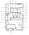
図に示す実施例によってこの発明を説明すると、1は空気調和機の枠体、2は枠体1内に設置した冷媒を圧縮する圧縮機、3は圧縮機2で圧縮された高温高圧となった冷媒が送られるコンデンサ、4はコンデンサ3で液化した冷媒が送られるエバポレータであり、コンデンサ3とエバポレータ4の間には図示せざる減圧器が取付けられ、減圧器を通過した冷媒はエバポレータ4内で気化し、冷媒の気化熱によって周囲を冷却する。また、エバポレータ4で気化した冷媒は圧縮機2に戻され、再び圧縮機2で圧縮された冷媒がコンデンサ3に送られて循環している。
The present invention will be described with reference to the embodiments shown in the drawings. 1 is a frame of an air conditioner, 2 is a compressor for compressing a refrigerant installed in the
5aはコンデンサ3を通過する空気流を作る温風ファン、3aはコンデンサ3を通過した空気が流れる温風経路、3bは枠体1の背面に設けた温風吹出口、3cは温風ファン5aの風を温風吹出口3bに誘導するファンケースであり、温風ファン5aによって送風される空気はコンデンサ3を通過し、圧縮機2で圧縮されて高温となった冷媒はコンデンサ3を通過するときに温風ファン5aによって送られる空気によって冷却されて液化し、コンデンサ3を通過した空気は高温となって温風吹出口3bから室内に戻される。
5a is a hot air fan that creates an air flow passing through the
5bはエバポレータ4を通過する空気流を作る冷風ファン、4aはエバポレータ4を通過した空気が流れる冷風経路、4bは枠体1の正面に設けた冷風吹出口、4cは冷風ファン5bの風を冷風吹出口5bに誘導するファンケースであり、液化した冷媒が減圧器で減圧されてエバポレータ4に送られると、液体の冷媒がエバポレータ4を通過する時に気化し、冷風ファン5bによってエバポレータ4に送られる空気は冷媒の気化熱によって冷却され、冷風となって冷風吹出口4bから吹出す。
5 b is a cool air fan that creates an air flow passing through the
6は枠体1内を温風経路3aと冷風経路4aとに分割する仕切板であり、図に示す実施例では仕切板6の上面側にエバポレータ4を配置した冷風経路4aが構成され、仕切板6の下面側にコンデンサ3を配置した温風経路3aが構成されており、仕切板6の上面に冷風ファン5bのファンケース4cを取付け、仕切板6の下面に温風ファン5aのファンケース3cを取付けている。
9は枠体1内の下部に設けたドレンタンク、10はエバポレータ4の下部に配置したドレン受け、10aはドレン受け10とドレンタンク9とを連絡するドレンパイプであり、室内空気がエバポレータ4を通過するときに空気中の水蒸気が結露してドレン水となり、ドレン受け10に落下する。そして、ドレン受け10のドレン水はドレンパイプ10aで誘導されてドレンタンク9に集められる。1aはドレンタンク9の側方の枠体1の壁面に形成したタンク取出し口であり、ドレンタンク9が満量になったときは枠体1のタンク取出口1aを開いてドレンタンク9を枠体1内から取出し、ドレンタンク9の排水を行うことができるようになっている。
Reference numeral 9 denotes a drain tank provided in the lower part of the
ところで、温風ファン5aや冷風ファン5bは重心が中心位置から外れていると回転時に振動や騒音を発生させる原因となるので、全てのファンについてバランス調整が必要であるが、従来は温風ファン5aと冷風ファン5bが別部品となっていたため、ファンのバランス調整にかかる時間が長くなり、製造時における作業工程や作業時間が多くかかり、コスト高になってしまっていた。 By the way, if the center of gravity of the hot air fan 5a or the cold air fan 5b deviates from the center position, it causes vibration and noise during rotation. Therefore, it is necessary to adjust the balance for all the fans. Since the 5a and the cold air fan 5b are separate parts, the time required for the balance adjustment of the fan becomes long, and it takes a lot of work processes and work time at the time of manufacture, resulting in high costs.
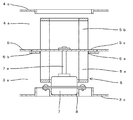
この発明は上記の課題を解決するもので、5は温風ファン5aと冷風ファン5bとを一体に構成した送風ファン、5cは温風ファン5aと冷風ファン5bの間に設けた円板状のベース板であり、温風ファン5aと冷風ファン5bはベース板5cによって接続され、ベース板5cの一方の面に温風ファン5aを形成し、他方の面に冷風ファン5bを形成しており、ベース板5cの外径は送風ファン5の外径よりも大きく設定している。
The present invention solves the above-described problems.
6aは仕切板6に設けた開口であり、開口6aの内径は送風ファン5を構成する温風ファン5aもしくは冷風ファン5bの外径よりも大きく、送風ファン5のベース板5cの外径よりも小さく設定している。
6 a is an opening provided in the
7は送風ファン5を駆動するファンモータ、7aはファンモータ7の駆動軸、8は仕切板6の開口6aと対向する位置の温風経路3aもしくは冷風経路4aの吸込口付近に設けたモータ収納部であり、ファンモータ7はモータ収納部8に収納され、ファンモータ7の駆動軸7aを開口6aに向かって伸ばしている。送風ファン5は温風ファン5aが温風経路3a側に位置し、冷風ファン5aが冷風経路4a側に位置するように仕切板6の開口6a内に装着し、送風ファン5はベース板5cによってファンモータ7の駆動軸7aに取付けられ、このとき送風ファン5のベース板5cが仕切板6の開口6aを塞いでおり、温風経路3aと冷風経路4aが独立した送風経路を構成している。
7 is a fan motor for driving the
また、送風ファン5が回転するために送風ファン5と開口6aとの間には若干の隙間が形成されるが、開口6aの外側では送風ファン5のベース板5cと仕切板6とが重なっているから隙間部分の距離を長くすることができ、この形状によって隙間に向かおうとする空気は抵抗を受け、隙間部分には空気が流れにくい構造にすることができたから、送風ファン5の送風能力を低下することなく温風経路3aと冷風経路4aとが独立した送風経路を形成することができた。
Further, since the
このように、温風ファン5aと冷風ファン5bが1個の送風ファン5として構成できれば、ファンのバランス調整が1回の作業でできるものとなり、作業時間が大幅に短縮できるものとなった。また、送風ファン5の組み付けに必要となるネジ等の部品や組立工程の数も減少するので、製造コストの低減が実現できるものとなった。
Thus, if the hot air fan 5a and the cold air fan 5b can be configured as one
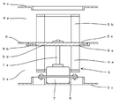
また、この発明の他の実施例において、6bは仕切板6の開口6aの周囲に形成した段部であり、該段部6bの内径は送風ファン5のベース板5cよりも大きくなるよう設定しており、送風ファン5を取付けたときに送風ファン5のベース板5cが段部6b内に位置するようになっている。この構成によって、送風ファン5と仕切板6の開口6aとの隙間部分の距離は長くなり、また空気が抵抗を受けやすい形状となるから、隙間部分に向かう空気の流れを確実に遮ることができるようになる。
In another embodiment of the present invention, 6b is a step formed around the opening 6a of the
また、請求項3の実施例において、5dは送風ファン5のベース板5cに形成した段部であり、段部5dの外径は送風ファン5の外径と同じ大きさに設定し、送風ファン5を取付けたときに段部5dが仕切板6の開口6a内に位置するようになっているから、この構成によっても送風ファン5と仕切板6の開口6aとの隙間部分の距離を長くとることができ、隙間部分に向かう空気の流れを確実に遮ることができる。
Further, in the embodiment of
また、図3に示すように、送風ファン5の段部5dと仕切板6の段部6bの両方を備えた構造にしてもよく、このような構成にすればより確実に空気の流れを遮ることができる。
Moreover, as shown in FIG. 3, you may make it the structure provided with both the step part 5d of the
また、従来では送風ファンやファンモータを取外すときには、ファンケースや仕切板などの送風経路の構成部品のほとんどを枠体1内から取外さなければならないため、非常にメンテナンス性が悪いものとなっていた。
Conventionally, when removing the blower fan or fan motor, most of the components of the blower path such as the fan case and the partition plate have to be removed from the inside of the
この発明は、送風ファン5やファンモータ7の着脱作業が容易にできる構造を実現したもので、図に示す実施例では、モータ収納部8が温風経路3a側のファンケース3cに形成されており、ファンモータ7は冷風経路4a側から仕切板6の開口6aを通してモータ収納部8に収納し、冷風経路4a側から開口6aを通してネジ止め固定できるようになっている。送風ファン5は冷風経路4a側から温風ファン5aを仕切板6の開口6aに挿通してファンモータ7の駆動軸7aに取付けており、送風ファン5のベース板5cが冷風経路4a側に位置している。
The present invention realizes a structure in which the
この構成によって、枠体1の天板と冷風ファン5bのファンケース4cを取外せば、ファンモータ7の駆動軸7aから送風ファン5を取外すことができるものとなり、仕切板6やファンモータ7を取付けた状態のまま送風ファン5のみを取外すことができるようになった。
With this configuration, if the top plate of the
また、送風ファン5を取外した後は、開口6aからドライバを差し込んでファンモータ7の固定ネジの取外し作業を行うことができ、開口6aからファンモータ7を取出すことができるものとなり、仕切板6を取外すことなくファンモータ7の交換作業ができるものとなった。
In addition, after removing the
したがって、送風ファン5やファンモータ7を分解する際には、冷風経路4a側のファンケース4cを外すだけでよく、仕切板6や温風経路3a側のファンケース3cといった他の部品を分解しなくても送風ファン5とファンモータ7の着脱作業が可能となり、メンテナンス性の向上が実現できるようになった。
Therefore, when disassembling the
なお、図に示す実施例では、コンデンサ3と温風経路3aが近接して配置された構造であるので、温風ファン5aの外径を開口6aの内径よりも小さく設定したものであるが、エバポレータ4と冷風経路4aが近接した配置された構造の場合は、冷風ファン5bの外径を開口6aの内径よりも小さく設定し、温風経路3a側から送風ファン5とファンモータ7の着脱作業を行うことができる。
In the embodiment shown in the figure, since the
1 枠体
2 圧縮機
3 コンデンサ
3a 温風経路
4 エバポレータ
4a 冷風経路
5 送風ファン
5a 温風ファン
5b 冷風ファン
5c ベース板
5d 段部
6 仕切板
6a 開口
6b 段部
7 ファンモータ
7a 駆動軸
8 モータ収納部
DESCRIPTION OF
Claims (4)
冷媒を圧縮する圧縮機2と、高温のガス状冷媒が送られるコンデンサ3と、液化した冷媒が減圧器を介して送られるエバポレータ4とを設け、該エバポレータ4で気化した冷媒が圧縮機2に戻される冷凍サイクルを構成すると共に、
前記コンデンサ3の温風経路3aに温風ファン5aを設け、エバポレータ4の冷風経路4aに冷風ファン5bを設けた空気調和機において、
前記枠体1内を分割してコンデンサ3の温風経路3aとエバポレータ4の冷風経路4aとを構成する仕切板6を設け、該仕切板6には温風経路3aと冷風経路4aとを連通する開口6aを設け、
かつ、前記温風ファン5aと冷風ファン5bは円板状のベース板5cを挟んで一体の送風ファン5を構成し、該送風ファン5はベース板5cの外径を開口6aの内径よりも大きく設定すると共に、温風ファン5aもしくは冷風ファン5bの外径を開口6aの内径よりも小さく設定し、
送風ファン5は外径を小さくした温風ファン5aもしくは冷風ファン5bを開口6aに挿通して温風ファン5aが温風経路3a側に、冷風ファン5bが冷風経路4a側に位置するように開口6aに配置し、
送風ファン5のベース板5cによってコンデンサ3の温風経路3aとエバポレータ4の冷風経路4aとが独立した送風経路を構成することを特徴とする空気調和機の送風構造。 In the frame 1 of the air conditioner,
A compressor 2 for compressing the refrigerant, a condenser 3 to which a high-temperature gaseous refrigerant is sent, and an evaporator 4 to which the liquefied refrigerant is sent via a decompressor are provided, and the refrigerant vaporized by the evaporator 4 is supplied to the compressor 2. Configure the returned refrigeration cycle,
In an air conditioner in which a hot air fan 5a is provided in the hot air path 3a of the condenser 3 and a cold air fan 5b is provided in the cold air path 4a of the evaporator 4,
A partition plate 6 is provided that divides the inside of the frame body 1 to constitute a hot air path 3a of the condenser 3 and a cold air path 4a of the evaporator 4, and the partition plate 6 communicates the hot air path 3a and the cold air path 4a. An opening 6a is provided,
The hot air fan 5a and the cold air fan 5b constitute an integrated blower fan 5 with a disc-shaped base plate 5c interposed therebetween, and the blower fan 5 has an outer diameter of the base plate 5c larger than the inner diameter of the opening 6a. And setting the outer diameter of the hot air fan 5a or the cold air fan 5b smaller than the inner diameter of the opening 6a,
The blower fan 5 is inserted such that the hot air fan 5a or the cold air fan 5b having a reduced outer diameter is inserted into the opening 6a so that the hot air fan 5a is located on the hot air path 3a side and the cold air fan 5b is located on the cold air path 4a side. 6a,
A blower structure of an air conditioner, wherein the base plate 5c of the blower fan 5 forms an independent blower path between the hot air path 3a of the condenser 3 and the cool air path 4a of the evaporator 4.
送風ファン5の仕切板5cが段部6b内に位置することを特徴とする請求項1に記載した空気調和機の送風構造。 A step portion 6b having an inner diameter larger than the outer diameter of the partition plate 5c of the blower fan 5 is formed outside the opening 6a of the partition plate 6.
The blower structure for an air conditioner according to claim 1, wherein the partition plate (5c) of the blower fan (5) is located in the step part (6b).
送風ファン5はベース板5cが仕切板6を挟んでファンモータ7とは反対側に位置するようにファンモータ7の駆動軸7aに取付け、
送風ファン5は仕切板6とファンモータ7を取付けた状態のままファンモータ7への着脱を可能とし、かつ、ファンモータ7は開口6aからモータ収納部8への着脱を可能としたことを特徴とする請求項1から請求項3のいずれかに記載した空気調和機の送風構造。
The hot air path 3 a or the cold air path 4 a is provided with a motor housing 8 toward the opening 6 a of the partition plate 6, and a fan motor 7 that drives the blower fan 5 is attached to the motor housing 8. While extending the shaft 7a to the opening 6a of the partition plate 6,
The blower fan 5 is attached to the drive shaft 7a of the fan motor 7 so that the base plate 5c is located on the opposite side of the fan motor 7 with the partition plate 6 in between.
The blower fan 5 can be attached to and detached from the fan motor 7 with the partition plate 6 and the fan motor 7 attached, and the fan motor 7 can be attached to and detached from the motor housing 8 from the opening 6a. The air blower structure for an air conditioner according to any one of claims 1 to 3.
Priority Applications (1)
| Application Number | Priority Date | Filing Date | Title |
|---|---|---|---|
| JP2004095129A JP4470552B2 (en) | 2004-03-29 | 2004-03-29 | Air conditioner ventilation structure |
Applications Claiming Priority (1)
| Application Number | Priority Date | Filing Date | Title |
|---|---|---|---|
| JP2004095129A JP4470552B2 (en) | 2004-03-29 | 2004-03-29 | Air conditioner ventilation structure |
Publications (2)
| Publication Number | Publication Date |
|---|---|
| JP2005282901A JP2005282901A (en) | 2005-10-13 |
| JP4470552B2 true JP4470552B2 (en) | 2010-06-02 |
Family
ID=35181499
Family Applications (1)
| Application Number | Title | Priority Date | Filing Date |
|---|---|---|---|
| JP2004095129A Expired - Fee Related JP4470552B2 (en) | 2004-03-29 | 2004-03-29 | Air conditioner ventilation structure |
Country Status (1)
| Country | Link |
|---|---|
| JP (1) | JP4470552B2 (en) |
-
2004
- 2004-03-29 JP JP2004095129A patent/JP4470552B2/en not_active Expired - Fee Related
Also Published As
| Publication number | Publication date |
|---|---|
| JP2005282901A (en) | 2005-10-13 |
Similar Documents
| Publication | Publication Date | Title |
|---|---|---|
| CN109595692B (en) | Air conditioner | |
| CN107850322B (en) | air conditioner | |
| KR102341728B1 (en) | Air conditioner | |
| CN107438527B (en) | Vehicle Air Conditioning System | |
| CN109891161B (en) | Air conditioner | |
| KR102784232B1 (en) | Air conditioner | |
| EP4018131B1 (en) | AIR CONDITIONING | |
| JP2009234473A (en) | Blower device | |
| JP4470552B2 (en) | Air conditioner ventilation structure | |
| KR100931077B1 (en) | Air conditioning for buses | |
| WO2010058666A1 (en) | Air conditioner | |
| KR100931078B1 (en) | Bus air conditioner | |
| CN115210094A (en) | Air conditioner for vehicle | |
| KR200334432Y1 (en) | Control box of airconditioner | |
| CN221146643U (en) | Hanging air conditioner | |
| JP7400129B2 (en) | Air conditioner indoor unit | |
| KR102695830B1 (en) | Air conditioner for vehicle | |
| CN221146667U (en) | Hanging air conditioner | |
| CN221593023U (en) | Hanging air conditioner | |
| JP7224523B2 (en) | Indoor unit and refrigeration cycle equipment | |
| KR100600070B1 (en) | Air conditioner | |
| KR102664645B1 (en) | Air conditioner for vehicle | |
| KR20090020377A (en) | Blower unit of vehicle air conditioner | |
| KR20090004961U (en) | Pipe support and connection structure of vehicle air conditioning case | |
| KR20090075008A (en) | Condensing Units for Air Conditioning Units for Buses |
Legal Events
| Date | Code | Title | Description |
|---|---|---|---|
| A621 | Written request for application examination |
Free format text: JAPANESE INTERMEDIATE CODE: A621 Effective date: 20070307 |
|
| A977 | Report on retrieval |
Free format text: JAPANESE INTERMEDIATE CODE: A971007 Effective date: 20100113 |
|
| TRDD | Decision of grant or rejection written | ||
| A01 | Written decision to grant a patent or to grant a registration (utility model) |
Free format text: JAPANESE INTERMEDIATE CODE: A01 Effective date: 20100209 |
|
| A01 | Written decision to grant a patent or to grant a registration (utility model) |
Free format text: JAPANESE INTERMEDIATE CODE: A01 |
|
| A61 | First payment of annual fees (during grant procedure) |
Free format text: JAPANESE INTERMEDIATE CODE: A61 Effective date: 20100222 |
|
| FPAY | Renewal fee payment (event date is renewal date of database) |
Free format text: PAYMENT UNTIL: 20130312 Year of fee payment: 3 |
|
| R150 | Certificate of patent or registration of utility model |
Ref document number: 4470552 Country of ref document: JP Free format text: JAPANESE INTERMEDIATE CODE: R150 Free format text: JAPANESE INTERMEDIATE CODE: R150 |
|
| FPAY | Renewal fee payment (event date is renewal date of database) |
Free format text: PAYMENT UNTIL: 20130312 Year of fee payment: 3 |
|
| FPAY | Renewal fee payment (event date is renewal date of database) |
Free format text: PAYMENT UNTIL: 20160312 Year of fee payment: 6 |
|
| LAPS | Cancellation because of no payment of annual fees |