JP4469723B2 - Tissue ablation device and method for cauterizing tissue - Google Patents
Tissue ablation device and method for cauterizing tissue Download PDFInfo
- Publication number
- JP4469723B2 JP4469723B2 JP2004554703A JP2004554703A JP4469723B2 JP 4469723 B2 JP4469723 B2 JP 4469723B2 JP 2004554703 A JP2004554703 A JP 2004554703A JP 2004554703 A JP2004554703 A JP 2004554703A JP 4469723 B2 JP4469723 B2 JP 4469723B2
- Authority
- JP
- Japan
- Prior art keywords
- microwave radiation
- probe
- symbol
- microwave
- previous
- Prior art date
- Legal status (The legal status is an assumption and is not a legal conclusion. Google has not performed a legal analysis and makes no representation as to the accuracy of the status listed.)
- Expired - Fee Related
Links
Images


Classifications
-
- A—HUMAN NECESSITIES
- A61—MEDICAL OR VETERINARY SCIENCE; HYGIENE
- A61B—DIAGNOSIS; SURGERY; IDENTIFICATION
- A61B18/00—Surgical instruments, devices or methods for transferring non-mechanical forms of energy to or from the body
- A61B18/18—Surgical instruments, devices or methods for transferring non-mechanical forms of energy to or from the body by applying electromagnetic radiation, e.g. microwaves
- A61B18/1815—Surgical instruments, devices or methods for transferring non-mechanical forms of energy to or from the body by applying electromagnetic radiation, e.g. microwaves using microwaves
-
- H—ELECTRICITY
- H05—ELECTRIC TECHNIQUES NOT OTHERWISE PROVIDED FOR
- H05B—ELECTRIC HEATING; ELECTRIC LIGHT SOURCES NOT OTHERWISE PROVIDED FOR; CIRCUIT ARRANGEMENTS FOR ELECTRIC LIGHT SOURCES, IN GENERAL
- H05B6/00—Heating by electric, magnetic or electromagnetic fields
- H05B6/64—Heating using microwaves
- H05B6/66—Circuits
- H05B6/68—Circuits for monitoring or control
- H05B6/686—Circuits comprising a signal generator and power amplifier, e.g. using solid state oscillators
-
- H—ELECTRICITY
- H05—ELECTRIC TECHNIQUES NOT OTHERWISE PROVIDED FOR
- H05B—ELECTRIC HEATING; ELECTRIC LIGHT SOURCES NOT OTHERWISE PROVIDED FOR; CIRCUIT ARRANGEMENTS FOR ELECTRIC LIGHT SOURCES, IN GENERAL
- H05B6/00—Heating by electric, magnetic or electromagnetic fields
- H05B6/64—Heating using microwaves
- H05B6/70—Feed lines
- H05B6/705—Feed lines using microwave tuning
-
- H—ELECTRICITY
- H05—ELECTRIC TECHNIQUES NOT OTHERWISE PROVIDED FOR
- H05B—ELECTRIC HEATING; ELECTRIC LIGHT SOURCES NOT OTHERWISE PROVIDED FOR; CIRCUIT ARRANGEMENTS FOR ELECTRIC LIGHT SOURCES, IN GENERAL
- H05B6/00—Heating by electric, magnetic or electromagnetic fields
- H05B6/64—Heating using microwaves
- H05B6/80—Apparatus for specific applications
- H05B6/806—Apparatus for specific applications for laboratory use
-
- A—HUMAN NECESSITIES
- A61—MEDICAL OR VETERINARY SCIENCE; HYGIENE
- A61B—DIAGNOSIS; SURGERY; IDENTIFICATION
- A61B18/00—Surgical instruments, devices or methods for transferring non-mechanical forms of energy to or from the body
- A61B2018/00636—Sensing and controlling the application of energy
- A61B2018/00642—Sensing and controlling the application of energy with feedback, i.e. closed loop control
-
- A—HUMAN NECESSITIES
- A61—MEDICAL OR VETERINARY SCIENCE; HYGIENE
- A61B—DIAGNOSIS; SURGERY; IDENTIFICATION
- A61B18/00—Surgical instruments, devices or methods for transferring non-mechanical forms of energy to or from the body
- A61B2018/00636—Sensing and controlling the application of energy
- A61B2018/00696—Controlled or regulated parameters
- A61B2018/00702—Power or energy
-
- A—HUMAN NECESSITIES
- A61—MEDICAL OR VETERINARY SCIENCE; HYGIENE
- A61B—DIAGNOSIS; SURGERY; IDENTIFICATION
- A61B18/00—Surgical instruments, devices or methods for transferring non-mechanical forms of energy to or from the body
- A61B2018/00636—Sensing and controlling the application of energy
- A61B2018/00696—Controlled or regulated parameters
- A61B2018/00755—Resistance or impedance
-
- A—HUMAN NECESSITIES
- A61—MEDICAL OR VETERINARY SCIENCE; HYGIENE
- A61B—DIAGNOSIS; SURGERY; IDENTIFICATION
- A61B18/00—Surgical instruments, devices or methods for transferring non-mechanical forms of energy to or from the body
- A61B2018/00636—Sensing and controlling the application of energy
- A61B2018/00773—Sensed parameters
- A61B2018/00779—Power or energy
-
- A—HUMAN NECESSITIES
- A61—MEDICAL OR VETERINARY SCIENCE; HYGIENE
- A61B—DIAGNOSIS; SURGERY; IDENTIFICATION
- A61B18/00—Surgical instruments, devices or methods for transferring non-mechanical forms of energy to or from the body
- A61B2018/00636—Sensing and controlling the application of energy
- A61B2018/00773—Sensed parameters
- A61B2018/00869—Phase
-
- A—HUMAN NECESSITIES
- A61—MEDICAL OR VETERINARY SCIENCE; HYGIENE
- A61B—DIAGNOSIS; SURGERY; IDENTIFICATION
- A61B18/00—Surgical instruments, devices or methods for transferring non-mechanical forms of energy to or from the body
- A61B2018/00636—Sensing and controlling the application of energy
- A61B2018/00773—Sensed parameters
- A61B2018/00875—Resistance or impedance
-
- A—HUMAN NECESSITIES
- A61—MEDICAL OR VETERINARY SCIENCE; HYGIENE
- A61B—DIAGNOSIS; SURGERY; IDENTIFICATION
- A61B18/00—Surgical instruments, devices or methods for transferring non-mechanical forms of energy to or from the body
- A61B18/18—Surgical instruments, devices or methods for transferring non-mechanical forms of energy to or from the body by applying electromagnetic radiation, e.g. microwaves
- A61B18/1815—Surgical instruments, devices or methods for transferring non-mechanical forms of energy to or from the body by applying electromagnetic radiation, e.g. microwaves using microwaves
- A61B2018/1823—Generators therefor
Abstract
Description
発明の背景
発明の分野
この発明は、組織をマイクロ波放射線で焼勺(ablation)するための装置および方法に関する。本願明細書においては、マイクロ波とは5GHz以上60GHz以下の周波数範囲を意味する。組織の焼勺には、14〜15GHzが用いられるのが好ましいが、この発明はそのような狭い範囲に限定されるものではない。
Background of the Invention
The present invention relates to an apparatus and method for ablating tissue with microwave radiation. In the present specification, the microwave means a frequency range of 5 GHz or more and 60 GHz or less. Although 14-15 GHz is preferably used for tissue cauterization, the present invention is not limited to such a narrow range.
先行技術の概要
癌治療の伝統的な方法においては、癌組織を機械的に切り取って除去し、かつ/または化学療法を行ない、通常その後に放射線療法を行なう。しかし、両方の方法には重大な問題があり、患者に深刻な外傷を引起すおそれがある。
SUMMARY OF THE PRIOR ART In traditional methods of cancer treatment, cancer tissue is mechanically excised and removed and / or chemotherapy is usually followed by radiation therapy. However, both methods have serious problems and can cause serious trauma to the patient.
生体組織に熱エネルギーを加えることは、細胞を殺す上で有効な方法である。これに鑑み、この発明は、マイクロ波を加えて生体組織を加熱することでこれを焼勺(破壊)するという方策を提案する。この方策によって、癌組織がこの態様で焼勺可能であることから癌治療において興味深い可能性が提示される。また、癌治療またはその他の状況下でマイクロ波により組織を焼勺するための好適な装置および方法が必要とされる。 Applying heat energy to living tissue is an effective method for killing cells. In view of this, the present invention proposes a measure of cauterizing (destroying) a living tissue by applying a microwave. This strategy presents an interesting potential in cancer therapy because cancer tissue can be cauterized in this manner. There is also a need for suitable devices and methods for ablating tissue by microwaves in cancer treatment or other situations.
発明の概要
上記に鑑み、この発明の第1の局面は、組織焼勺装置であって、
マイクロ波放射線の源と、
焼勺されるべき組織の中へ上記マイクロ波放射線を向けるためのプローブと、
前記マイクロ波放射線とは異なる周波数を有する信号を生成するための局部発振器と、
反射して上記プローブを通り上記源の方へ戻ってきたマイクロ波放射線の大きさおよび位相を検出するための第1の検出器とを備え、前記第1の検出器は前記局部発振器に接続され、上記装置はさらに、
前記源および前記プローブ間に、調整可能な複素インピーダンスを有するインピーダンス調整器を備える、装置を提供することができる。
In view of the above, a first aspect of the present invention is a tissue ablation device,
A source of microwave radiation,
A probe for directing the microwave radiation into the tissue to be cauterized;
A local oscillator for generating a signal having a frequency different from the microwave radiation;
A first detector for detecting the magnitude and phase of microwave radiation reflected back to the source through the probe, the first detector being connected to the local oscillator The device further includes
An apparatus can be provided comprising an impedance adjuster having an adjustable complex impedance between the source and the probe.
本願明細書においては、文脈が他を要求する場合を除き、「接続」という用語は、直接的な接続のみならず、1つ以上の構成要素を介在させた間接的な接続をも包含する。 In this specification, unless the context requires otherwise, the term “connection” encompasses not only a direct connection, but also an indirect connection through one or more components.
また、上記組織焼勺装置は、
或る周波数を有するマイクロ波放射線の源と、
前記源に接続されたプローブとを備え、前記プローブは、焼勺されるべき前記組織の中へ前記マイクロ波放射線を向けるように構成され、上記装置はさらに、
前記マイクロ波放射線の前記周波数とは異なる周波数を有する、信号を生成するための局部発振器と、
前記マイクロ波放射線のうち、反射して前記プローブを通り前記源の方へ戻ってきた反射部分の大きさおよび位相を検出するための第1の検出器とを備え、
前記第1の検出器は、前記反射した放射線および前記局部発振器により生成された前記信号に基づいて前記マイクロ波放射線の前記反射部分の大きさおよび位相を判定するよう
に構成され、上記装置はさらに、
前記マイクロ波放射線の源に接続された入力部と、前記プローブに接続された出力部とを有するインピーダンス調整器を備え、前記入力部および出力部はそれぞれ複素インピーダンスを有し、前記出力部の前記複素インピーダンスは調整可能である、場合もある。
The tissue ablation device is
A source of microwave radiation having a frequency;
A probe connected to the source, the probe configured to direct the microwave radiation into the tissue to be ablated, the apparatus further comprising:
A local oscillator for generating a signal having a frequency different from the frequency of the microwave radiation;
A first detector for detecting the size and phase of the reflected portion of the microwave radiation reflected back through the probe toward the source;
The first detector is configured to determine the size and phase of the reflected portion of the microwave radiation based on the reflected radiation and the signal generated by the local oscillator, the apparatus further comprising: ,
An impedance adjuster having an input connected to the source of microwave radiation and an output connected to the probe, each of the input and output having a complex impedance; The complex impedance may be adjustable.
上記インピーダンス調整器の前記調整可能な複素インピーダンスが調整可能であるため、反射される放射線の量を最小限に抑えることができ、こうして組織へエネルギーを送り届ける効率の向上が可能となる。 Since the adjustable complex impedance of the impedance adjuster is adjustable, the amount of reflected radiation can be minimized, thus improving the efficiency of delivering energy to the tissue.
一般的に、インピーダンス調整器の出力部でのインピーダンスと、負荷(たとえば焼勺されている組織)のインピーダンスとを整合させれば、プローブの末端にある負荷(たとえば組織)で反射してプローブを通り戻ってくる放射線のレベルは最小限に抑えられる。 In general, if the impedance at the output of the impedance adjuster is matched to the impedance of the load (eg, ablated tissue), the probe is reflected by the load (eg, tissue) at the end of the probe. The level of radiation that returns is minimized.
インピーダンス調整器とプローブとを接続するには、同軸ケーブルまたは導波管といった伝達手段を用いることができる。マイクロ波放射線がインピーダンス調整器の出力部とプローブの末端との間で進む距離がλ/2の倍数に等しい場合(λは放射線の波長)、インピーダンス調整器の出力インピーダンスと、プローブの末端にある負荷(たとえば組織)のインピーダンスとを整合させることは単純な作業である。そうでない場合、インピーダンスを整合させて反射を最小限に抑えることはなお可能であるが、伝達手段およびプローブのインピーダンスもまた考慮する必要がある(たとえば、インピーダンス調整器の出力インピーダンスを、負荷、伝達手段およびプローブを合計したインピーダンスに整合させる必要がある)。したがって、本質的なことではないが、前記伝達手段の長さが調整可能であり、前記伝達手段と前記プローブとを合計した長さがλ/2の倍数に等しくなるように調整可能であることが好ましい。 A transmission means such as a coaxial cable or a waveguide can be used to connect the impedance adjuster and the probe. If the distance that microwave radiation travels between the output of the impedance adjuster and the end of the probe is equal to a multiple of λ / 2 (where λ is the wavelength of the radiation), the output impedance of the impedance adjuster and the end of the probe Matching the impedance of the load (eg tissue) is a simple task. If not, it is still possible to match the impedance to minimize reflections, but the impedance of the transmission means and the probe must also be taken into account (eg, the output impedance of the impedance adjuster, load, transfer) Means and probe must be matched to the total impedance). Therefore, although not essential, the length of the transmission means can be adjusted, and the total length of the transmission means and the probe can be adjusted to be equal to a multiple of λ / 2. Is preferred.
検出器が大きさ(すなわち振幅または電力)の情報のみを生成する場合、複素インピーダンスを速やかに調整して反射放射線を効果的に最小化することは不可能であろう。位相の情報を用いるもう1つの利点として、信号対雑音比が劣悪なときでも位相の差が測定できることが挙げられる。したがって、検出器は大きさおよび位相の両方の情報を生成することが求められる。位相情報を生成するためには、局部発振器を用いてマイクロ波放射線の周波数とは異なる周波数の信号を生成することが必要である。これによって、検出されたマイクロ波放射線の位相と、上記局部発振器からの信号の位相とを比較することが可能となる。 If the detector produces only magnitude (ie amplitude or power) information, it may not be possible to quickly adjust the complex impedance to effectively minimize the reflected radiation. Another advantage of using phase information is that the phase difference can be measured even when the signal-to-noise ratio is poor. Thus, the detector is required to generate both magnitude and phase information. In order to generate the phase information, it is necessary to generate a signal having a frequency different from the frequency of the microwave radiation using a local oscillator. This makes it possible to compare the phase of the detected microwave radiation with the phase of the signal from the local oscillator.
通常、上記検出器は、上記局部発振器からの信号を、上記マイクロ波放射線と混合するためのミキサを含むことになる。たとえば、上記検出器では、反射での大きさおよび位相を検出する際、ヘテロダイン検出(反射した放射線またはそこから導き出した信号を局部発振器からの信号と混合すること)を採用することができる。これに代えて、上記位相の検出には、反射したマイクロ波放射線の位相と局部発振器の信号の位相とを比較するように構成された位相比較器を用いてもよい。反射したマイクロ波放射線は、1つ以上の周波数変換器の中を通過させてからミキサまたは位相比較器に入ることとしてもよい。これは位相比較器を採用した場合に特に有効であるが、なぜなら位相比較器とは、その傾向としてより低い周波数でより正確に動作するものだからである。 Typically, the detector will include a mixer for mixing the signal from the local oscillator with the microwave radiation. For example, the detector can employ heterodyne detection (mixing reflected radiation or a signal derived therefrom with a signal from a local oscillator) when detecting the magnitude and phase in reflection. Alternatively, a phase comparator configured to compare the phase of the reflected microwave radiation and the phase of the signal of the local oscillator may be used for the phase detection. The reflected microwave radiation may pass through one or more frequency converters before entering the mixer or phase comparator. This is particularly effective when a phase comparator is employed, since phase comparators tend to operate more accurately at lower frequencies.
好ましくは、上記装置はさらに、順方向のマイクロ波放射線(前記源から前記プローブの方へ向けられた放射線)の大きさおよび位相を検出するための第2の検出器を備える。 Preferably, the apparatus further comprises a second detector for detecting the magnitude and phase of forward microwave radiation (radiation directed from the source towards the probe).
上記第1の検出器と同様、マイクロ波放射線の位相が判定できるよう局部発振器を設けることが必要である。好ましくは、上記第1の検出器についてと同じ局部発振器が用いられる。したがって、たとえば上記検出器がミキサを用いる場合、各々の検出器がそれ自身
のミキサを有して、両方のミキサが共通の局部発振器に接続されることになる。このような場合、2つ以上のミキサを駆動するために局部発振器からの出力を緩衝する必要があることがある。これに代えて、各々のミキサを異なる局部発振器に接続する場合もあるが、この場合、位相を検出して適当なインピーダンス調整を行なうことは、局部発振器信号間の差のためより困難となる。
Similar to the first detector, it is necessary to provide a local oscillator so that the phase of the microwave radiation can be determined. Preferably, the same local oscillator as for the first detector is used. Thus, for example, if the detector uses a mixer, each detector will have its own mixer and both mixers will be connected to a common local oscillator. In such a case, it may be necessary to buffer the output from the local oscillator to drive more than one mixer. Alternatively, each mixer may be connected to a different local oscillator, but in this case, it is more difficult to detect the phase and make appropriate impedance adjustments due to differences between the local oscillator signals.
「順方向の」マイクロ波放射線の大きさおよび位相を検出するための第2の検出器がある場合、適当なインピーダンス調整を決定することがより容易となる。検出器が1つしかない場合、当該装置の特性(たとえば、インピーダンス調整器の入力部とプローブ/組織界面との間で当該装置によって引起される位相の変化)についてより多くの仮定をする必要がある。 If there is a second detector for detecting the magnitude and phase of the “forward” microwave radiation, it will be easier to determine the appropriate impedance adjustment. If there is only one detector, more assumptions need to be made about the characteristics of the device (eg, the phase change caused by the device between the impedance adjuster input and the probe / tissue interface). is there.
さらに、第3の検出器が設けられることが好ましい。この第3の検出器は、反射したマイクロ波放射線の大きさおよび位相を検出するように構成されるか、または「順方向の」マイクロ波放射線の大きさおよび位相を検出するように構成される。上記第3の検出器によれば、上記の適当な(複素)インピーダンス調整をより正確に判定することが可能となる。第3の検出器がある場合、インピーダンス調整器自体の調整に起因する複素インピーダンスの変化を監視することが可能である。また、インピーダンス調整器の入力部および出力部間の位相の差を直接判定可能とすることもできる。この情報は、行なわれるべき適当な調整を判定する際に有用である。 Furthermore, a third detector is preferably provided. This third detector is configured to detect the magnitude and phase of the reflected microwave radiation or is configured to detect the magnitude and phase of the “forward” microwave radiation. . According to the third detector, the appropriate (complex) impedance adjustment can be determined more accurately. If there is a third detector, it is possible to monitor the change in complex impedance due to the adjustment of the impedance adjuster itself. It is also possible to directly determine the phase difference between the input unit and the output unit of the impedance adjuster. This information is useful in determining the appropriate adjustment to be made.
上記第2の検出器と同様、上記第3の検出器は局部発振器に接続される必要がある。これは第1および第2の検出器のうち一方または両方についてと同じ局部発振器であっても、異なるものであってもよい。すべての検出器は1つの共通の局部発振器を共有することが好ましく、やはり緩衝を伴い得る。 Similar to the second detector, the third detector needs to be connected to a local oscillator. This may be the same local oscillator as for one or both of the first and second detectors, or it may be different. All detectors preferably share a common local oscillator and may also be buffered.
位相比較器が使用される場合、上記第1ならびに(もしあれば)第2および第3の検出器を組合せて1つのユニットにしてもよい。 When a phase comparator is used, the first and second (if any) and third detectors may be combined into one unit.
上記または各々の局部発振器は、上記マイクロ波放射線の源とは別個で独立のものとしてもよい。 The or each local oscillator may be separate and independent from the source of microwave radiation.
代替的に、上記または各々の局部発振器は、前記マイクロ波放射線の源から導き出されるが異なる周波数を有する信号を生成してもよい。典型的にこれは、前記マイクロ波放射線の源からの信号をより低い周波数へと変換する周波数変換器によって行なわれる。次に、上記より低い周波数「局部発振器」信号を上記検出器のミキサに入力して順方向または反射したマイクロ波放射線を混合しても、上記信号を位相比較器のための基準信号として用いてもよい。マイクロ波放射線の源に接続された周波数変換器は、実質的に上記局部発振器として動作する。 Alternatively, the or each local oscillator may generate a signal derived from the source of microwave radiation but having a different frequency. This is typically done by a frequency converter that converts the signal from the source of microwave radiation to a lower frequency. The lower frequency “local oscillator” signal can then be input to the detector mixer to mix forward or reflected microwave radiation and use the signal as a reference signal for the phase comparator. Also good. A frequency converter connected to a source of microwave radiation substantially operates as the local oscillator.
もう1つの手法としては、別個の局部発振器を設ける一方、局部発振器信号を前記マイクロ波放射線の源からの信号と混合して、この混合した結果としての信号を上記検出器に入力するというものがある。典型的には、上記ミキサと上記検出器それ自体(これはそれ自体が上述のようなミキサを含み得る)との間にフィルタを設けて不所望の周波数をいずれもフィルタ除去することになる。 Another approach is to provide a separate local oscillator while mixing the local oscillator signal with the signal from the source of microwave radiation and inputting the resulting signal to the detector. is there. Typically, a filter will be provided between the mixer and the detector itself (which may itself include a mixer as described above) to filter out any unwanted frequencies.
上記インピーダンス調整器は、検出されてディスプレイ上に表示される大きさおよび位相関係のデータに応じて人間のオペレータによって動作させられてもよい。しかしながら、インピーダンス調整器の前記調整可能な複素インピーダンスは、前記検出器により検出された放射線の大きさおよび位相に基づいてコントローラにより自動的に調整されるのが
好ましい。上記コントローラは、たとえば集積回路またはコンピュータの形態をとることができる。
The impedance adjuster may be operated by a human operator in response to magnitude and phase relationship data that is detected and displayed on the display. However, the adjustable complex impedance of the impedance adjuster is preferably automatically adjusted by the controller based on the magnitude and phase of the radiation detected by the detector. The controller can take the form of an integrated circuit or a computer, for example.
上記コントローラは、前記検出器により検出された上記放射線の大きさおよび位相における変動に応じて動的に(実時間で)前記調整可能な複素インピーダンスを調整するように構成されるのが好ましい。この場合、当該組織の特性が焼勺プロセス中に変化するのに伴ってインピーダンスを調整することが可能となる。効果的に動的制御を行なうために、調整時間は当該組織の弛緩時間(または反応時間)未満とする。 The controller is preferably configured to adjust the adjustable complex impedance dynamically (in real time) in response to variations in the magnitude and phase of the radiation detected by the detector. In this case, the impedance can be adjusted as the tissue properties change during the ablation process. In order to effectively perform dynamic control, the adjustment time is less than the relaxation time (or reaction time) of the tissue.
上記インピーダンス調整器は任意の好適な形態をとることができる。たとえば、上記インピーダンス調整器として半導体装置またはスタブ同調器を用いることができる。スタブ同調器の場合、この同調器は、1つ、2つ、3つまたはそれ以上のスタブを有し得る。3スタブ同調器が好ましいが、それはこの場合、広範囲にわたる複素インピーダンス(理論的にはスミスチャート上の任意のインピーダンス)が採用可能となるからである。別の可能な方策としては、位相調整器および大きさ調整器を含むインピーダンス調整器を設けるというものがある(たとえば2つの可変長ラインまたは可変長ラインおよび同調スタブ。上記可変長ラインは同軸ラインまたはストリップラインであり得る)。 The impedance adjuster can take any suitable form. For example, a semiconductor device or a stub tuner can be used as the impedance adjuster. In the case of a stub tuner, the tuner may have one, two, three or more stubs. A three stub tuner is preferred because in this case a wide range of complex impedances (theoretically any impedance on the Smith chart) can be employed. Another possible strategy is to provide an impedance adjuster including a phase adjuster and a size adjuster (eg, two variable length lines or variable length lines and a tuning stub. The variable length lines can be coaxial lines or Can be stripline).
上記インピーダンス調整器を制御するための電気的に活性化可能なアクチュエータが設けられる場合もある。上記インピーダンス調整器としてスタブ同調器が用いられる場合、上記電気的に活性化可能なアクチュエータとして、たとえば1つ以上の圧電素子またはサーボモータを用いることができ、これによりスタブを制御してインピーダンスを調整する。上記アクチュエータを前記コントローラによって制御することでインピーダンス整合の制御を自動化することができる。 There may be an electrically activatable actuator for controlling the impedance adjuster. When a stub tuner is used as the impedance adjuster, for example, one or more piezoelectric elements or servo motors can be used as the electrically activatable actuator, thereby adjusting the impedance by controlling the stub. To do. Control of impedance matching can be automated by controlling the actuator by the controller.
好ましくは、マイクロ波放射線の源は、安定な単一の周波数源、たとえば狭帯域フィルタを伴う広帯域源または位相固定した源である。これはたとえば反射したマイクロ波放射線において位相変化を検出する際に有益である。上記放射線源としては、VCO(電圧制御発振器)またはDRO(誘電体共振発振器)を用いることができるが、当業者にはその他可能な放射線源が明らかであろう。上記放射線源を同調可能とすることで、制御された態様で周波数が変化できるようにしてもよい。 Preferably, the source of microwave radiation is a stable single frequency source, such as a broadband source with a narrow band filter or a phase locked source. This is useful, for example, in detecting phase changes in reflected microwave radiation. The radiation source can be a VCO (Voltage Controlled Oscillator) or DRO (Dielectric Resonant Oscillator), but other possible radiation sources will be apparent to those skilled in the art. By making the radiation source tunable, the frequency may be varied in a controlled manner.
上記プローブとしては、同軸プローブまたは導波管(これは負荷をかけられていてもいなくてもよい)を用いることができる。 As the probe, a coaxial probe or a waveguide (which may or may not be loaded) can be used.
好ましくは、上記プローブは、生体組織に貫入するように構成され、たとえば鋭い先端を持たせてもよい。これによって、上記プローブは、焼勺されるべき腫瘍付近またはその内部に達するまで当該組織の中に挿入することが可能となる。こうして、マイクロ波を腫瘍に対して効果的に照射することができる。特に、キーホールサージャリーで挿入することの可能なプローブとするのが有利である。これに従い、プローブの外径は1mm未満であるのが好ましい。このように小さなサイズにすることによって、患者に対する外傷が最小限に抑えられ、さらにプローブから放射されるマイクロ波放射線のエネルギー密度が増大する。 Preferably, the probe is configured to penetrate a living tissue, and may have a sharp tip, for example. This allows the probe to be inserted into the tissue until it reaches or near the tumor to be ablated. Thus, the microwave can be effectively irradiated to the tumor. In particular, it is advantageous to use a probe that can be inserted by keyhole surgery. Accordingly, the outer diameter of the probe is preferably less than 1 mm. This small size minimizes trauma to the patient and increases the energy density of the microwave radiation emitted from the probe.
上記プローブとしては、中心導体と、外側の導体と、これら2つの導体間の誘電体とを有する同軸プローブを用いることができる。さらに、上記外側の導体上に1つ以上のバラン(平衡から不平衡への変換器)を設けることで、上記外側の導体における戻り電流を最小限にしてもよい(この電流は患者または当該装置の使用者にショックを生じさせるおそれがある)。上記バランは、上記外側の導体を取囲む導電性材料からなるリングまたは鞘の形態をとることができる。また、誘電体のバランを採用してもよい。 As the probe, a coaxial probe having a center conductor, an outer conductor, and a dielectric between these two conductors can be used. In addition, one or more baluns (balanced to unbalanced converters) may be provided on the outer conductor to minimize the return current in the outer conductor (this current may be the patient or the device). May cause shock to the user. The balun may take the form of a ring or sheath made of a conductive material surrounding the outer conductor. A dielectric balun may also be used.
上記装置は、上記プローブから外へ向けられる「入射」(順方向)マイクロ波放射線と、反射したマイクロ波放射線とを分離するためのセパレータを有するのが好ましい。このセパレータは、たとえばサーキュレータの形態をとることができる。これに代えて、電力3dBカプラを用いてもよい。
The apparatus preferably includes a separator for separating “incident” (forward) microwave radiation directed outward from the probe and reflected microwave radiation. This separator can take the form of a circulator, for example. Alternatively, a
好ましくは、上記装置は、反射した放射線の一部を上記第1の検出器に向けるための第1のカプラを有する。任意の好適なカプラ、たとえば単一ポートカプラを用いてもよいが、6ポートカプラが有利であろう。さらに、出て行く(順方向)放射線の一部を第2の検出器に向けるための第2のカプラを設けてもよい。また、放射線を第3の検出器に向けるための第3のカプラを設けてもよい。この第3のカプラは、反射放射線カプラか、または順方向放射線カプラのいずれかであり得る。上記カプラの指向性を高くすることによって、順方向の放射線および反射した放射線間の良好な差別化を確実にすることが好ましい。 Preferably, the apparatus comprises a first coupler for directing a portion of the reflected radiation to the first detector. Any suitable coupler, such as a single port coupler, may be used, but a 6 port coupler would be advantageous. In addition, a second coupler may be provided for directing some of the outgoing (forward) radiation to the second detector. A third coupler for directing radiation to the third detector may also be provided. This third coupler can be either a reflective radiation coupler or a forward radiation coupler. It is preferable to ensure good differentiation between forward and reflected radiation by increasing the directivity of the coupler.
この発明に従う方法は、最も大まかには、生体組織にプローブを接触して置くステップと、前記組織のうち少なくとも一部を焼勺するように、マイクロ波放射線を、前記プローブを通して前記組織へ送り届けるステップとを備える。上記方法は癌の治療に使用されるのが好ましい。上記組織は、癌部分または腫瘍を有し得る。この場合、上記放射線を用いて前記癌部分または腫瘍を焼勺し、好ましくは周囲の癌でない組織を実質的に無傷に残す。 The method according to the present invention most generally comprises placing a probe in contact with biological tissue and delivering microwave radiation through the probe to the tissue so as to cauterize at least a portion of the tissue. With. The method is preferably used for the treatment of cancer. The tissue can have a cancerous part or a tumor. In this case, the radiation is used to cauterize the cancerous part or tumor, preferably leaving the surrounding non-cancerous tissue substantially intact.
或る種の処置においては、極めて細い(直径1mm未満の)プローブが有利であるが、この発明はこれに限定されない。 For certain procedures, very thin probes (less than 1 mm in diameter) are advantageous, but the invention is not so limited.
この発明は乳癌の治療に対して特に有用であると考えられる。もう1つの可能な用途として脳腫瘍の治療が挙げられる。しかしこの発明はこれらの用途に限定されず、肺癌、肝臓癌(たとえば肝臓転移)、前立腺癌、皮膚癌、結腸直腸癌腫、またはあらゆる癌腫であって固形の腫瘍が存在し焼勺可能であるものに対する治療にも利用可能である。当業者にはその他の用途が明らかであろう。実施例によっては、この発明は癌以外の状態、たとえば皮膚病または脳の病気(特に視神経付近の領域、ただしこれに限られない)の治療にも有用であろう。 This invention is believed to be particularly useful for the treatment of breast cancer. Another possible use is the treatment of brain tumors. However, the present invention is not limited to these uses, and lung cancer, liver cancer (eg, liver metastasis), prostate cancer, skin cancer, colorectal carcinoma, or any carcinoma that has a solid tumor and can be cauterized It can also be used for treatment. Other uses will be apparent to those skilled in the art. In some embodiments, the invention may also be useful in the treatment of conditions other than cancer, such as skin diseases or brain diseases, particularly but not limited to areas near the optic nerve.
したがって、この発明の第2の局面は、組織を焼勺する方法であって、
マイクロ波放射線の源を用いてマイクロ波放射線を生成するステップと、
プローブを生体組織に接触して置くまたはプローブを生体組織の中に挿入するステップと、
上記組織を焼勺するように、前記マイクロ波放射線を、前記プローブを通して上記組織の中へ向けるステップと、
反射して上記プローブを通り戻ってきたマイクロ波放射線の大きさおよび位相を、第1の検出器および局部発振器を用いて検出するステップと、
前記第1の検出器により検出されたマイクロ波放射線の大きさおよび位相に基づいて前記源と前記プローブとの間にあるインピーダンス調整器の複素インピーダンスを調整するステップとを備える、方法を提供することができる。
Therefore, the second aspect of the present invention is a method for cauterizing tissue,
Generating microwave radiation using a source of microwave radiation;
Placing the probe in contact with the biological tissue or inserting the probe into the biological tissue;
Directing the microwave radiation through the probe and into the tissue to cauterize the tissue;
Detecting the magnitude and phase of the microwave radiation reflected back through the probe using a first detector and a local oscillator;
Adjusting the complex impedance of an impedance adjuster between the source and the probe based on the magnitude and phase of microwave radiation detected by the first detector. Can do.
また、上記方法は、
マイクロ波放射線の源を用いて、或る周波数を有するマイクロ波放射線を生成するステップと、
プローブを生体組織に接触して置くまたはプローブを生体組織の中に挿入するステップと、
上記組織を焼勺するように、前記マイクロ波放射線を、前記源からインピーダンス調整
器を通して前記プローブを通し前記組織の中へ向けるステップとを備え、前記インピーダンス調整器は、前記源に接続された入力部と前記プローブに接続された出力部とを有し、前記入力部および前記出力部はそれぞれ複素インピーダンスを有し、上記方法はさらに、
反射して上記プローブを通り戻ってきた反射マイクロ波放射線の大きさおよび位相を、第1の検出器および局部発振器を用いて検出するステップを備え、前記局部発振器は、前記マイクロ波放射線の前記周波数とは異なる周波数を有する信号を生成し、前記第1の検出器は、上記反射した放射線または前記反射した放射線から導き出した信号と組合わせて前記局部発振器信号を用いて、前記反射した放射線の大きさおよび位相を判断し、上記方法はさらに、
反射して前記プローブを通り戻ってきたマイクロ波放射線の量が最小化されるように、前記第1の検出器により検出された前記反射したマイクロ波放射線の前記大きさおよび位相に基づいて前記インピーダンス調整器の前記出力部の前記複素インピーダンスを調整するステップを備える、場合もある。
Also, the above method
Generating microwave radiation having a frequency using a source of microwave radiation;
Placing the probe in contact with the biological tissue or inserting the probe into the biological tissue;
Directing the microwave radiation from the source through an impedance adjuster through the probe and into the tissue to ablate the tissue, the impedance adjuster comprising an input connected to the source And an output unit connected to the probe, the input unit and the output unit each have a complex impedance, and the method further comprises:
Detecting the magnitude and phase of reflected microwave radiation reflected back through the probe using a first detector and a local oscillator, the local oscillator comprising the frequency of the microwave radiation Generating a signal having a different frequency from the first detector, wherein the first detector uses the local oscillator signal in combination with the reflected radiation or a signal derived from the reflected radiation to produce a magnitude of the reflected radiation. Determining the length and phase, the method further comprises:
The impedance based on the magnitude and phase of the reflected microwave radiation detected by the first detector so that the amount of microwave radiation reflected back through the probe is minimized. In some cases, the method includes a step of adjusting the complex impedance of the output unit of the adjuster.
好ましくは、この方法は、この発明の第1の局面の装置を用いて癌を治療する方法である。 Preferably, the method is a method of treating cancer using the apparatus of the first aspect of the invention.
好ましくは、上記プローブが組織の中に挿入されて当該組織内の癌腫瘍付近または好ましくはその内部にプローブの一端が達し、次にマイクロ波放射線がプローブを通されて前記癌腫瘍を焼勺する。 Preferably, the probe is inserted into the tissue so that one end of the probe reaches or near the cancer tumor in the tissue, and then microwave radiation is passed through the probe to ablate the cancer tumor. .
好ましくは、上記プローブが当該腫瘍付近またはその中まで挿入可能となるように上記プローブからのマイクロ波放射線を用いて当該組織内に経路を切開する。これは腫瘍近くまたはその中までプローブを持って行く効果的な方法である。 Preferably, a path is cut into the tissue using microwave radiation from the probe so that the probe can be inserted near or into the tumor. This is an effective way to bring the probe close to or into the tumor.
好ましくは、治療されている組織および/または身体からプローブを出す際、プローブからのマイクロ波放射線を用いてプローブの経路を封着する。 Preferably, when the probe is removed from the tissue and / or body being treated, the probe's pathway is sealed using microwave radiation from the probe.
好ましくは、前記マイクロ波放射線の源から前記プローブの中へ向けられる順方向のマイクロ波放射線の大きさおよび位相は、第2の検出器および局部発振器によって検出され、前記インピーダンス調整器の前記調整可能な複素インピーダンスは、前記第1および第2の検出器により検出された大きさおよび位相に基づき、たとえば上記順方向の放射線および反射した放射線間の位相および大きさの差に基づいて調整される。 Preferably, the magnitude and phase of forward microwave radiation directed into the probe from the source of microwave radiation is detected by a second detector and a local oscillator and the tunable of the impedance adjuster The complex impedance is adjusted based on the magnitude and phase detected by the first and second detectors, for example, based on the phase and magnitude difference between the forward and reflected radiation.
好ましくは、順方向の放射線または反射した放射線のいずれかについての大きさおよび位相を検出するために第3の検出器が使用され、前記インピーダンス調整器の前記調整可能な複素インピーダンスは、前記第1、第2および第3の検出器によって生成された情報に基づき、たとえば上記各検出器間の大きさおよび位相の差に基づいて調整される。 Preferably, a third detector is used to detect the magnitude and phase for either forward or reflected radiation, and the adjustable complex impedance of the impedance adjuster is the first , Based on the information generated by the second and third detectors, for example, based on the magnitude and phase difference between the detectors.
好ましくは、上記インピーダンス調整器の前記調整可能な複素インピーダンスは、反射して前記プローブを通り戻ってくる放射線の量を最小化するように、前記検出器により検出された上記大きさおよび位相に基づいてコントローラによって自動的に調整される。 Preferably, the adjustable complex impedance of the impedance adjuster is based on the magnitude and phase detected by the detector so as to minimize the amount of radiation reflected back through the probe. Automatically adjusted by the controller.
上記インピーダンス調整は、検出される大きさおよび位相が変化するのに伴って動的に(実時間で)実行されるのが好ましい。これによって、焼勺プロセス中に当該組織のインピーダンスが変化するのに伴ってインピーダンス調整器の前記調整可能な複素インピーダンスを調整することが可能となる。これによって、プローブおよびケーブルの加熱(長期間にわたる当該装置内の反射エネルギーによって引起される)が最小限に抑えられ、速やかで効率的かつ制御された焼勺プロセスの実現を支援することができる。 The impedance adjustment is preferably performed dynamically (in real time) as the detected magnitude and phase change. This makes it possible to adjust the adjustable complex impedance of the impedance adjuster as the tissue impedance changes during the ablation process. This minimizes heating of the probe and cable (caused by reflected energy in the device over a long period of time) and can help to achieve a rapid, efficient and controlled ablation process.
その他の好ましい特徴点が前掲の特許請求の範囲に示される。 Other preferred features are set forth in the appended claims.
この発明の第3の局面においては、焼勺されるべき組織の中にマイクロ波放射線を送り届けるための細長のマイクロ波プローブであって、前記プローブは、細長部分と、前記細長部分の一端にある先端とを有し、前記先端は、セラミック材料から形成され、マイクロ波放射線を組織の中に送り届けるように構成される、マイクロ波プローブが提供される。 In a third aspect of the invention, an elongated microwave probe for delivering microwave radiation into the tissue to be ablated, wherein the probe is at the elongated portion and at one end of the elongated portion. A microwave probe is provided, the tip being formed from a ceramic material and configured to deliver microwave radiation into the tissue.
上記先端にセラミック材料が好適である理由は、セラミックが比較的硬質であり、電磁場を集束させるのに有利な高い誘電率(εr)を有するとともに、上記先端の加熱を低減する良好な熱伝導率を有することができるからである。 The reason why ceramic material is suitable for the tip is that the ceramic is relatively hard, has a high dielectric constant (ε r ) advantageous for focusing the electromagnetic field, and good heat conduction that reduces heating of the tip It is because it can have a rate.
上記先端は円錐状または円蓋状であるのが好ましい。これは上記プローブから出て行くマイクロ波を集束させる助けとなる。 The tip is preferably conical or circular. This helps to focus the microwave exiting the probe.
上記セラミックとしてはマイクロ波セラミックを用いることが好ましい。たとえば、パシフィック・セラミックス社(Pacific Ceramics Inc.)製のマイクロ波セラミックが採用できる。 A microwave ceramic is preferably used as the ceramic. For example, microwave ceramics manufactured by Pacific Ceramics Inc. can be used.
好ましくは、上記マイクロ波セラミックの誘電率は1よりも大きく、より好ましくはマイクロ波周波数においてεr=6.5からεr=270である。好ましくは、上記マイクロ波セラミックは、該当するマイクロ波周波数において低い損失(tan δ)を有する。 Preferably, the dielectric constant of the microwave ceramic is greater than 1, more preferably ε r = 6.5 to ε r = 270 at the microwave frequency. Preferably, the microwave ceramic has a low loss (tan δ) at the corresponding microwave frequency.
この発明の第4の局面においては、同軸の組織焼勺プローブであって、内側の導体と、前記内側の導体を取囲む誘電体と、前記誘電体を取囲む導電性鞘と、前記鞘上にある1つ以上のバランとを有し、上記または各々のバランは吹付け誘電体を含む、プローブが提供される。好ましくは、上記または各々のバランはさらに、前記吹付け誘電体を取囲む外側の導体を含む。上記誘電体が吹付け誘電体であるため、バランを極めて小さくすることが可能である。これはプローブの断面積が小さくかつ/または周波数が高い場合に必要である。 According to a fourth aspect of the present invention, there is provided a coaxial tissue ablation probe, an inner conductor, a dielectric surrounding the inner conductor, a conductive sheath surrounding the dielectric, and the sheath One or more baluns are provided, wherein the or each balun includes a blowing dielectric. Preferably, the or each balun further comprises an outer conductor surrounding the blowing dielectric. Since the dielectric is a sprayed dielectric, the balun can be made extremely small. This is necessary when the cross-sectional area of the probe is small and / or the frequency is high.
この発明の第5の局面に従うと、同軸の組織焼勺プローブのためのバランを作製する方法であって、同軸プローブにおける外側の導電性鞘の外側表面に対して液体または粉末状の誘電体を吹付けまたはその他で配置するステップと、前記誘電体が液体の場合に上記液体を凝固させるステップとを備え、こうして上記バランが形成される、方法が提供される。 According to a fifth aspect of the present invention, there is provided a method of making a balun for a coaxial tissue ablation probe, wherein a liquid or powdered dielectric is applied to an outer surface of an outer conductive sheath in the coaxial probe. A method is provided comprising spraying or otherwise placing and solidifying the liquid when the dielectric is a liquid, thus forming the balun.
この発明の第4および第5の局面の両方において、好ましくは、前記プローブは、波長λのマイクロ波放射線での使用に対して設計され、上記バランの、前記プローブの軸方向での長さは、およそλ/4またはその奇数倍数に等しい。 In both the fourth and fifth aspects of the invention, preferably the probe is designed for use with microwave radiation of wavelength λ, and the length of the balun in the axial direction of the probe is , Approximately equal to λ / 4 or an odd multiple thereof.
この発明の第6の局面は、外科手術用装置であって、
組織の焼勺に適した第1の周波数のマイクロ波放射線の源と、
上記源から、焼勺されるべき組織の中へマイクロ波放射線を向けるためのプローブと、
上記源からの前記マイクロ波放射線を変調しないOFF状態、および、上記源からのマイクロ波放射線を変調して前記第1の周波数よりも小さい第2の周波数のパルスにするON状態、を有する変調器とを備え、前記第2の周波数は組織の切開に適したものである、装置が提供される。したがって、上記プローブは2つの異なる周波数を出力できる。すなわち、一方は組織焼勺(たとえば癌組織の焼勺)に対して最適なものにされ、他方は組織の切開(たとえば健康な組織を切って癌組織に達する)に対して最適なものにされる。しかし、この装置が必要とする放射線源はただ1つである。その方が、放射線源が別個に2
つある場合よりも好ましい。
A sixth aspect of the present invention is a surgical apparatus,
A source of microwave radiation of a first frequency suitable for tissue ablation;
A probe for directing microwave radiation from the source into the tissue to be ablated;
A modulator having an OFF state in which the microwave radiation from the source is not modulated, and an ON state in which the microwave radiation from the source is modulated into a second frequency pulse smaller than the first frequency. And the second frequency is suitable for tissue incision. Thus, the probe can output two different frequencies. That is, one is optimized for tissue ablation (eg, cancer tissue ablation) and the other is optimized for tissue incision (eg, cutting healthy tissue to reach cancer tissue). The However, this device requires only one radiation source. In that case, two separate radiation sources
It is preferable to the case where there is one.
好ましくは、組織焼勺のための第1の周波数は1GHz以上であり、より好ましくは13GHz以上である。一実施例では14〜15GHzの範囲内である。 Preferably, the first frequency for tissue ablation is 1 GHz or higher, more preferably 13 GHz or higher. In one embodiment, it is in the range of 14-15 GHz.
組織切開のための第2の周波数は好ましくは10kHzから500MHzの範囲内である。組織切開の際にはこのような周波数が効果的であるとわかった。より好ましくは、500kHzから30MHzの範囲内である。 The second frequency for tissue dissection is preferably in the range of 10 kHz to 500 MHz. Such a frequency has been found to be effective during tissue dissection. More preferably, it is in the range of 500 kHz to 30 MHz.
好ましくは、上記装置はさらに、前記変調器と前記プローブとの間に低域フィルタを備え、前記低域フィルタは、前記第1の周波数を通す第1の状態と、前記第2の周波数を通すが前記第1の周波数をフィルタ除去する第2の状態とを有する。上記装置はフィルタなしでも動作するが、上記フィルタは上記第2の周波数での切開効果を向上させる。 Preferably, the apparatus further comprises a low pass filter between the modulator and the probe, wherein the low pass filter passes the first state through which the first frequency passes and the second frequency through. Has a second state of filtering out the first frequency. Although the device operates without a filter, the filter improves the incision effect at the second frequency.
前記変調器は、前記第2の周波数を変化させることが可能であるのが好ましい。 The modulator is preferably capable of changing the second frequency.
前記低域フィルタは、上記変調器周波数が変化したときに第2の状態において通過帯域を変化させることが可能であるのが好ましい。これによって当該装置はより柔軟なものとなる。 The low-pass filter is preferably capable of changing the passband in the second state when the modulator frequency changes. This makes the device more flexible.
上述したこの発明についての第1から第6の局面における特徴点のうち任意のものを互いに組合せることも可能である。 It is possible to combine any of the feature points in the first to sixth aspects of the present invention described above.
以下、この発明の各実施例について、添付の図面を参照して説明を行なう。 Embodiments of the present invention will be described below with reference to the accompanying drawings.
発明の詳細な説明
装置の概観
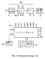
図1において、マイクロ波で組織を焼勺するための装置のブロック図が示される。この装置は、マイクロ波放射線を生成および制御するためのユニット100と、包括的に参照番号190の下で一まとめにして、プローブ5とプローブにマイクロ波放射線を送り届けるための伝達手段4とを有する。プローブ5を用いることで、マイクロ波放射線を組織6に加えて組織を焼勺することができる。
Detailed Description of the Invention
Device Overview In FIG. 1, a block diagram of a device for ablating tissue with microwaves is shown. The apparatus comprises a
組織6は、マイクロ波のうちいくらかを反射してプローブ5およびユニット100の中へ戻す可能性があることから、装置100,200を組織6に対してインピーダンス整合させる方策が必要となる。この方策は、反射したマイクロ波を監視し、それに応じてインピーダンスを調整するための構成要素(包括的に参照番号3の下で一まとめにする)によって実現される。当該装置におけるこの重要な部分3では、反射したマイクロ波の大きさおよび位相の両方が考慮される。この実施例では、この部分3は、ユニット100内のサブユニットとして設けられる。これについては下でより詳細に説明する。
Since
ユニット100は、マイクロ波放射線源1と、放射線源1からのマイクロ波を増幅する増幅システム2と、マイクロ波を検出してインピーダンスを調整するための構成要素3と、電源120と、増幅システム2およびユニット3を適宜制御するためのコントローラ101とを含む。
The
ユニット100は、伝達手段4およびホルダ5aを介してプローブ5に接続される。伝達手段4は、マイクロ波を伝達するのに適したものである限りどのような形態をとってもよく、たとえば導波管または同軸ケーブルを用いることができる。伝達手段4とプローブ
とを合計した長さがλ/2の倍数に等しい(ここでλは、放射線源1により生成されるマイクロ波放射線の波長)のが有利であるが、それはこの場合伝達手段4およびプローブがマイクロ波放射線に対して透明になり、その結果これらについてのインピーダンスが、組織6と装置100,200とのインピーダンス整合時に無視できるようになるからである。こうしてインピーダンス整合が容易となる。したがって、場合により長さ調整器を設けて伝達手段の有効長さを調整可能にする。考えられ得る長さ調整器としては、入れ子式コネクタ、同軸トロンボーン位相調整器またはピンダイオード位相調整器などがある。インピーダンス整合については下でより詳細に述べる。
The
マイクロ波増幅システム2は、プリアンプ10および電力増幅器20を有する。これらについては下でより詳細に説明する。
The
ユニット3は、反射して当該装置の中へ戻ってきたマイクロ波(反射マイクロ波放射線)の大きさおよび位相を検出するための第1の検出器60と、プローブ5の方へそしてここを通して向けられるマイクロ波(「順方向マイクロ波放射線」)の大きさおよび位相を検出するための第2の検出器30とを有する。これら2種類のマイクロ波放射線はその方向によって区別されるため、上記各検出器は、それぞれ順方向検出器30および逆方向(または反射放射線)検出器60と呼ぶことができる。
The
ユニット3は、プローブの方へ進むマイクロ波と、反射してプローブの中に戻ってきたマイクロ波(たとえば組織6で反射したマイクロ波)とを分離するためのサーキュレータ40を有する。上記各検出器は順方向マイクロ波と反射マイクロ波とを区別できるように設計されるのが好ましいが、以下の理由からサーキュレータ40も設けることが極めて好ましい。すなわちサーキュレータ40は、反射した放射線が増幅システム2の中へ戻って向けられることを防ぐための切離し部として働く。反射放射線が増幅システム2に達すると、増幅器が損傷を受けるおそれがあるからである。
The
サーキュレータ40は、周囲の回路と接続するための3つのポートC1,C2,C3を有する。ポートC1は、順方向検出器30および増幅システム2を介して放射線源1へ接続し、ポートC2は、インピーダンス調整器50、逆方向検出器60そして伝達手段4を介してプローブへ接続し、ポートC3はダンプ負荷70に接続する。C1から入った放射線はC2でサーキュレータから出る。サーキュレータにC2から入った反射放射線はC3でサーキュレータから出る。サーキュレータとしては、イットリウム・鉄・ガーネット(YIG)電力サーキュレータを使用することができる。
The
検出器
上述のように、検出器30,60は、マイクロ波放射線の大きさおよび位相の両方を検出する。図2は、ユニット3、特に検出器30,60をより詳細に示す概略図である。反射してプローブを通り戻ってきたマイクロ波放射線の大きさおよび位相を検出するための第1の電力検出器60は、サーキュレータのポートC2に接続されたインピーダンス調整器50に接続された方向性カプラ200を含む。方向性カプラ200は、反射した放射線のうち一部をミキサ220に向け、ここでこの放射線は局部発振器230からの信号と混合される。
Detector As described above, the
この混合によって中間周波数信号が生成され、この信号は、上記ミキサ220の出力部に接続された検出素子240により検出され、こうして反射した放射線の大きさおよび位相の両方を導き出すことが可能となる。換言すると、上記システムはヘテロダイン検出システムである。混合によって生じる不所望の周波数を除去するために、検出素子240とミキサ220との間にフィルタ(図示せず)を設けてもよい。大きさおよび位相の情報はコントローラ101に送られる。これに代わる実施例では、検出素子240の機能をコン
トローラ自身で実行してもよい。このようなシステムにおいては、中間周波数は、局部発振器からの信号の周波数と反射した放射線の周波数との差に基づいて生成されるのが好ましい。しかしながら、中間周波数は、局部発振器からの信号の周波数および反射した放射線の周波数の源であることも可能である。
This mixing produces an intermediate frequency signal that is detected by a
位相および大きさを両方とも検出できるには、局部発振器230を設けることが必要である。実施例によっては、反射した放射線は、局部発振器からの信号と混合させる前に、方向性カプラとミキサ220との間に設けた周波数変換器および/またはその他の素子を通すことによって容易に加工できるようにしてもよい。
In order to be able to detect both phase and magnitude, it is necessary to provide a
第2の検出器30は方向性カプラ250を含む。方向性カプラ250は、入来する放射線の大部分を電力サーキュレータ40のポートC1に結合するが、一部を第2のミキサ260に向ける。第2のミキサ260は、上述の局部発振器230に接続されるのに加え、第1の検出器60について上述したのと同じ態様で構成された検出素子280に接続される。
The
代替的な一実施例では、第1の検出器60および第2の検出器30を、図2に示すように1つの共通の発振器230に接続するのでなく、それぞれ異なる局部発振器に接続してもよい。
In an alternative embodiment, the
当業者であれば、上記の各構成要素は、図1および図2に示す順序にある必要はないことが理解されるであろう。たとえば、各検出器およびインピーダンス調整器3は、伝達手段4のプローブ5側の端部にあってもよい。また、各構成要素を分離しかつ/またはその順序を変えることもまた可能であろう。たとえば、順方向カプラ250を、サーキュレータ40とインピーダンス調整器50との間に配することもでき、またはサーキュレータ40とダンプ負荷210との間に配してもよい。また、反射した放射線を検出するための第1の検出器60のみを有する装置とすることも可能であるが、順方向および逆方向両方の検出器があればより多くの情報が得られ、これによってインピーダンス調整器に対する適当なインピーダンス調整を求めることで反射放射線量を最小限にすることが容易となる。
One skilled in the art will appreciate that the components described above need not be in the order shown in FIGS. For example, each detector and
図18は、図2の例に代わる構成例であって、ミキサをなくした代わりに位相比較器65を用いたものを示す。同様の参照番号は図1および図2と同様の要素を表わす。図2での説明と同様、順方向カプラ250、サーキュレータ40、インピーダンス調整器50、および逆方向カプラ200が設けられる。しかしながら、順方向カプラ250からの順方向マイクロ波放射線はまず、図17の構成例と同様に局部発振器として働く周波数変換器62および大きさセンサ(この場合DCセンサ)61に送られ、そしてこれらの各々から位相比較器65に送られる。周波数変換器62は、マイクロ波放射線を、位相比較器65で扱うことの可能な低い周波数へと変換する。逆方向カプラ200は、大きさセンサ63および周波数変換器64に接続され、これらの各々は、順方向カプラ250についての対応の部分61,62と同様に位相比較器に接続される。位相比較器65は、大きさセンサ61,63から大きさ(電力)情報入力を、そして周波数変換器62,64からは変換された周波数信号を受取り、これより順方向および逆方向のマイクロ波放射線の大きさおよび位相を求め、この情報をコントローラ101に送る。
FIG. 18 shows a configuration example instead of the example of FIG. 2, in which a
局部発振器230は、放射線源1により生成されるマイクロ波放射線の周波数とは異なる周波数の信号を生成することが重要である。このことはミキサが用いられる図2の構成において重要であるが、それはヘテロダイン検出には2つの異なる周波数が必要だからである。また、周波数変換器62が局部発振器として働く図18の構成においても重要であるが、それは位相比較器とは、放射線源1で生成されたマイクロ波周波数よりもはるかに低い周波数しか満足に扱うことのできないものだからである。
It is important that the
図2の例では、局部発振器230は放射線源1とは別個で独立である。しかしながら、局部発振器において、マイクロ波放射線源1から導き出された信号を生成させることも可能である。たとえば、図17に示すように、マイクロ波放射線源1とプリアンプシステム10との間にカプラ22を設け、マイクロ波放射線のうち一部を周波数変換器24へ迂回させるように構成する場合もある。周波数変換器24は、実質的に局部発振器として働く。周波数変換器24はミキサ220に接続され、放射線源1からのマイクロ波放射線の周波数とは異なる(通常これよりはるかに低い)周波数の信号をミキサ220に出力する。逆方向カプラ200は、反射したマイクロ波放射線をミキサ220に向ける。反射マイクロ波放射線の大きさおよび位相は、ミキサ220の出力部に接続された検出素子240によって判定される。当該装置内のその他の部分は図17には示さず、図1,2で上述したのと同じものである。
In the example of FIG. 2, the
図16はこの発明の装置の代替的な一実施例を示し、同様の参照番号は上述と同様の要素を表わす。ここには主な相違点が2つある。第1に、包括的に参照番号33で表わす追加の検出器が、サーキュレータ40とインピーダンス調整器50との間に位置付けられている。当業者であれば理解できるように、その他の場所、たとえばサーキュレータ40とダンプ負荷210との間、またはサーキュレータ40と放射線源1との間に位置付けてもよい。図16の実施例では、この第3の検出器33は反射マイクロ波放射線を検出するように構成されるが、これに代わる実施例では、順方向マイクロ波放射線を検出するように構成されてもよい。第3の検出器33は、サーキュレータ40およびインピーダンス調整器50間に位置付けられる逆方向カプラ34と、逆方向カプラ34に接続されたミキサ35と、検出素子36とを含む。第3の検出器33は、上述の第1および第2の検出器と同様に動作する。第3の検出器33はさらに、インピーダンス調整器50で行なうべき適当なインピーダンス調整を決定する際に有用な情報を出力し、これにより反射マイクロ波放射線の量を最小限に抑える。
FIG. 16 shows an alternative embodiment of the apparatus of the present invention, wherein like reference numerals represent like elements as described above. There are two main differences here. First, an additional detector, generally designated by
図16の実施例における第2の主な相違点は、局部発振器230からの信号が、マイクロ波放射線源1からの信号とミキサ45において混合されることである。第1、第2および第3の検出器に入力されるのは、局部発振器230から直接与えられる信号でなく、ミキサ45からの出力信号である。ミキサ45の出力部はフィルタ46に接続される。フィルタ46は、ミキサで生じた不所望の周波数(通常はより低い周波数)を除去して、所望の周波数を第1、第2および第3の検出器のミキサ220,260,35の入力部へ通す。図16ではまた、それぞれの検出器のミキサ220,260,35および対応の検出素子240,280,36間にそれぞれ設けられたフィルタ221,281,35aを示す。
The second major difference in the embodiment of FIG. 16 is that the signal from the
局部発振器信号を、マイクロ波放射線源から導き出したもの(図17)またはマイクロ波放射線源からの信号と混合したもの(図16)とする利点は、マイクロ波放射線源の周波数または位相に変化があれば、それがいずれも検出器に送られる信号に反映されることである。 The advantage of having a local oscillator signal derived from a microwave radiation source (FIG. 17) or mixed with a signal from a microwave radiation source (FIG. 16) is that there is a change in the frequency or phase of the microwave radiation source. For example, it is reflected in the signal sent to the detector.
インピーダンス調整器およびコントローラ
この実施例におけるインピーダンス調整器は三重スタブ同調器50の形態をとる。これについては下でより詳細に説明する。実施例によっては、これに代えて、インピーダンスを調整する単一もしくは二重スタブ同調器または半導体装置を用いてもよい。
Impedance adjuster and controller The impedance adjuster in this embodiment takes the form of a
インピーダンス調整器50は、検出器により検出された大きさおよび位相に基づいてコントローラ101によって制御され、こうして反射マイクロ波放射線の量を最小限にする。この実施例では、コントローラ101は集積回路である。その他の実施例では、適当な
ソフトウェアを伴うコンピュータとしてもよい。
The
インピーダンス調整器50は、図1および図16に示す他の構成要素を介してマイクロ波放射線源1に接続された入力部と、1つ以上の他の構成要素を介してプローブ5に接続された出力部とを有する。通常、マイクロ波放射線源1は固定の実インピーダンスを有し、これはインピーダンス調整器50の入力部のインピーダンスと整合される。したがって、ほとんどの場合、インピーダンス調整器50の入力部のインピーダンスは固定である。インピーダンス調整器50の出力部の複素インピーダンスは調整可能とする。インピーダンス調整器50の出力部の複素インピーダンスを調整することによって、組織で反射してプローブ5を通って戻ってくる放射線の量を最小限にすることが可能となる。マイクロ波放射線がインピーダンス調整器50の出力部とプローブ5の末端との間で進む距離が、マイクロ波放射線の波長を2で割ったものの倍数に等しい場合、インピーダンス調整器50の出力部の複素インピーダンスを組織6のそれと直接整合させることが可能である。これに対し、上記のような倍数に等しくない場合、インピーダンス調整器の出力部と組織/プローブ界面との間にある構成要素のインピーダンスを考慮に入れる必要がある(これは可能ではあるが、コントローラ101で必要となる計算が増加する)。
The
さらに、オペレータが当該装置の機能を監視できるようにするユーザインターフェイス110が設けられる。監視される機能としては特に、反射での大きさおよび位相や、任意にはさらに順方向での大きさおよび位相、プローブを当てる負荷(組織6)の測定インピーダンス、およびマイクロ波放射線が当てられた時間量が挙げられる。
In addition, a
ユーザインターフェイス110ではさらに、オペレータは、当該装置を制御、コントローラ101で増幅システム2を制御することでマイクロ波の電力を調整、およびコントローラ101または電源120によりマイクロ波を当てる動作を開始・停止させることが可能となる。この制御に対しては、足踏みスイッチまたはペダル105で影響を与えることが可能である。
In the
発明の装置についてのいくつかの考えられ得る用途
この装置は、癌組織を焼勺して癌を治療するために使用可能である。これはキーホールサージャリーなどで実行される。キーホールサージャリーでは、プローブを挿入するための小さな通路を周囲の組織に切開してプローブを癌腫瘍に届かせる。それからマイクロ波を用いて腫瘍を焼勺することができるが、上述のように反射マイクロ波の大きさおよび位相を監視することによって当該装置のインピーダンスを適当に調整してプローブの中へ戻るマイクロ波の反射を最小限にすることができる。マイクロ波(放射線源1によって生成される)の放射は、プローブが腫瘍付近にあるときまたはそれより以前に行なうことができる。考えられる一方法として、プローブ5から放射されるマイクロ波を用いて、周囲の組織を通じてプローブを挿入するための経路を切開するというものである。
Some possible uses for the device of the invention The device can be used to cauterize cancer tissue and treat cancer. This is performed in keyhole surgeries and the like. In keyhole surgeries, a small passage for inserting the probe is cut into the surrounding tissue to allow the probe to reach the cancer tumor. The microwave can then be used to ablate the tumor, but as described above, the microwave is returned to the probe by appropriately adjusting the impedance of the device by monitoring the magnitude and phase of the reflected microwave. Reflection can be minimized. Radiation of microwaves (generated by radiation source 1) can be performed when the probe is near the tumor or earlier. One possible method is to use a microwave radiated from the
以下、放射線源1、増幅システム2およびプローブ5についてより詳細に説明する。
Hereinafter, the
マイクロ波放射線源
この実施例においては、マイクロ波放射線源1は、14GHzから14.5GHzの間で周波数が調整可能な電圧制御発振器(VCO)である。実施例によっては、異なる種類のマイクロ波源、たとえば誘電体共振発振器(DRO)や、または異なる周波数範囲を用いてもよい。VCO制御信号FoAおよび監視信号FoMは、コントローラ101(図1を参照)を出入りするよう送られる。
Microwave Radiation Source In this embodiment, the
マイクロ波放射線源1は、0dBmで電力を出力可能であり、かつその電力レベルがその出力周波数帯域全体にわたって+/−0.5dBで一定であり続けることができるのが
好ましい。出力周波数は上記帯域内で(コントローラ101を介して)変化させることができ、これを用いて当該装置を微調整することができる。たとえば、上記帯域内には、増幅システム2で回路共鳴が生じて最大電力を達成できる特定の周波数があり得る。また、上記帯域全体にわたって周波数を掃引することによって、或る器具同調、たとえば、プローブ5および/または伝達手段4が共鳴にはわずかに短すぎる場合に周波数を増加させる、またはその逆、を行なってもよい。
The
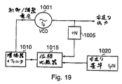
マイクロ波放射線源は安定である(すなわち安定な出力を生成する)ことが極めて好ましい。これは上述の位相検出の助けとなる。安定性を達成する一方策として、位相を固定した放射線源を用いることがある。図19に位相固定式マイクロ波放射線源の可能な一構成例を示す。VCO1001がマイクロ波放射線を生成し、これは図1で既に示したように増幅システム2を介して当該装置の残りの部分へ出力される。VCOからの出力信号の一部は周波数変換器1005に結合される。周波数変換器1005は、上記信号の周波数を減少させてこれを位相比較器1015の第1の入力部に入力する。位相比較器の第2の入力部には、安定な基準信号、たとえば水晶発振器からの信号が入力される。これを用いて、マイクロ波放射線の所望の周波数f0からの変動があればそれを追跡する。安定な基準により与えられる周波数はf0/Nである。これが安定であり得るのは、低い周波数においてはたとえば水晶発振器といった極めて安定な発振器を利用できるからである。周波数変換器1005は、VCOから出力された周波数をN分の1に減少させる。位相比較器1015は、上記2つの入力信号の周波数間および/または位相間の差を増幅器・フィルタ1010に出力し、これはVCOの入力部にフィードバックしてその制御電圧を適当に制御および調整し、こうして出力信号の周波数および位相におけるあらゆる不所望の変動を補正する。
It is highly preferred that the microwave radiation source is stable (ie, produces a stable output). This helps the phase detection described above. One way to achieve stability is to use a radiation source with a fixed phase. FIG. 19 shows one possible configuration example of a phase-locked microwave radiation source. The
図20は、マイクロ波放射線源から安定な出力を得るための代替的な一構成例を示す。広帯域の放射線源1030(これは合成したものであり得る)を用いて広範囲のマイクロ波周波数を生成し、これを狭帯域フィルタ1040に出力して、出力すべき狭い周波数帯域(または1周波数)を選択させる。このようにして、マイクロ波放射線の出力の安定が可能となる。
FIG. 20 shows an alternative configuration for obtaining a stable output from a microwave radiation source. A broadband radiation source 1030 (which can be synthesized) is used to generate a wide range of microwave frequencies that are output to a
増幅システム
増幅システム2は、プリアンプ段またはユニット10および電力増幅段またはユニット20を含む。
Amplification System The
図3に電力増幅段20の可能な一構成例を示す。プリアンプ段10の出力部からマイクロ波放射線がプリアンプドライバ300に入力される。プリアンプドライバ300は放射線をスプリッタ310に出力する。スプリッタ310は、この信号を4つの電力増幅器320,330,340,350間に分割する。信号は各々の電力増幅器によって増幅されてから出力され、コンバイナ360によって再結合される。コンバイナ360は、再結合した信号を各検出器およびインピーダンス調整器3に出力する。
FIG. 3 shows one possible configuration example of the
電力増幅器の種類選択は、マイクロ波放射線源1の周波数出力によって決定される。14〜14.5GHz範囲の場合、GaAs FETが特に好適である。これは当該帯域幅全体にわたって43dBm(20W)の1dB圧縮点および6dBの電力利得を有することが好ましい。東芝マイクロ波半導体グループのTIM1414−20を用いることができる。この種類の電力増幅器が用いられる場合、理論的な最大出力電力レベルは49dBm(80W)である。
The type selection of the power amplifier is determined by the frequency output of the
図3の例では、スプリッタ310およびコンバイナ360は、4分の1波長マイクロストリップ素子である。
In the example of FIG. 3,
これに代えて、上記増幅システムは、複数の電力増幅器間に入力信号を分割するための1つ以上のマイクロ波カプラと、上記電力増幅器から出力された信号を再結合するための1つ以上のマイクロ波カプラとを有してもよい。この場合、電力増幅器のうち1つが故障した場合、不整合になったエネルギーを、故障した電力増幅器が接続されたカプラにおける隔離されたポートに接続されたダンプ負荷へそらすことができ、他の電力増幅器には影響が及ばないという利点がある。 Alternatively, the amplification system includes one or more microwave couplers for dividing an input signal between a plurality of power amplifiers, and one or more microwave couplers for recombining signals output from the power amplifiers. You may have a microwave coupler. In this case, if one of the power amplifiers fails, the mismatched energy can be diverted to a dump load connected to an isolated port in the coupler to which the failed power amplifier is connected. There is an advantage that the amplifier is not affected.
図4は、マイクロ波カプラを用いた構成の一例である。プリアンプドライバ400は図3の例と同様に使用されるが、電力増幅器間に信号を分割する、および増幅した信号を再結合するための構成は異なる。この例では、信号は2つの段で分割される。プリアンプドライバ400の出力部は、2つの出力部(図4のポート3,4)間に信号を分割するカプラに接続される。これら出力部のうち第1の出力部からの信号は回路の第1のアーム410aに向けられ、ここでもう1つのカプラ415によって再び2つに分割される。このカプラ415は、この時点で二度分割されている信号を第1の電力増幅器420および第2の電力増幅器430に向け、それから信号はカプラ435によって再結合される。カプラ435はこの信号をカプラ460の入力部に出力する。
FIG. 4 is an example of a configuration using a microwave coupler. The
カプラ410の第2のポートからの信号は回路の第2のアーム410bに向けられる。これは上述の第1のアーム410aと実質的に同じ構造を有し、すなわち、第1のポートと第2のポートとの間に信号を分割するカプラ417を有する。上記カプラの第1のポートは第3の電力増幅器440の入力部に結合され、第2のポートは第4の電力増幅器450に結合される。上記第3の電力増幅器440および第4の電力増幅器450の出力部は、入力信号を結合するための別のカプラ455の第1および第2の入力ポートに結合され、上記別のカプラ455の出力部は、2つのアーム10a,10bからの信号を結合するカプラ460に接続される。
The signal from the second port of the
図4では、電力増幅器としてTM414−20増幅器を用いているが、任意の好適な電力増幅器が適当な変更を伴って使用可能である。三菱のMEFK44 A4045増幅器が有利であろう。 In FIG. 4, a TM414-20 amplifier is used as the power amplifier, but any suitable power amplifier can be used with appropriate modifications. A Mitsubishi MEFK44 A4045 amplifier would be advantageous.
カプラ410,415,435,417,455,460は、その2出力部の間に等しく電力を分割、またはその2入力部から等しく結合するのが好ましい。このようなカプラは3dB90°カプラとして知られる。
上述のように、図4の構成の利点は、電力増幅器のうち1つが故障した場合、不整合になったエネルギーが、故障した電力増幅器の接続されたカプラにおける隔離されたポートに接続されたダンプ負荷にそらされることである。このため、その他の電力増幅器は影響を受けない。 As described above, the advantage of the configuration of FIG. 4 is that if one of the power amplifiers fails, the mismatched energy is dumped to an isolated port in the connected coupler of the failed power amplifier. To be diverted to the load. For this reason, other power amplifiers are not affected.
当業者には、電力増幅段についてその他の構成が明らかであろう。 Other configurations for the power amplification stage will be apparent to those skilled in the art.
増幅システム2は電力レベル制御部を有する。電力レベル制御部は、コントローラ101によって制御されて所望のレベルの出力電力を与える。この実施例では、電力レベル制御部は、増幅システム2のプリアンプ段10にある。
The
図5にプリアンプ段10についての可能な一構成例を示す。マイクロ波放射線源1の出力部は、プリアンプ段10の入力部に接続される。プリアンプ段10は複数のプリアンプ510,520,530,540を含み、これらは図5の例では直列に接続される。プリアンプのうち1つ(この例では第2のプリアンプ520)は可変利得を有することとし、
当該装置によって出力されるマイクロ波の電力レベルを制御するために用いることができる。可変利得プリアンプ520の利得はコントローラ101によって制御される。好ましくは、可変利得プリアンプは、その線形領域でのみ動作するよう構成されるが、ルックアップ表または類似のソフトウェア機能を設けて低レベル入力電力需要を代表的なバイアス電圧へ変換する場合、線形動作領域の外側で動作させてもよい。
FIG. 5 shows one possible configuration example for the
It can be used to control the power level of the microwave output by the device. The gain of the
図6に代替的な一構成例を示す。図5の例と同様、複数のプリアンプ610,620,630,640が設けられるが、電力レベル制御部はピンダイオード減衰器650である(そして、このピンダイオード減衰器650はコントローラ101によって制御される)。ピンダイオード減衰器650は、直列接続されるプリアンプのうち2つの間に配される。図6の例では、ピンダイオード減衰器650は第1のプリアンプ610と第2のプリアンプ620との間に配される。ピンダイオード減衰器650としては、反射型ピンダイオード減衰器または吸収型減衰器を用いることができる。
FIG. 6 shows an alternative configuration example. As in the example of FIG. 5, a plurality of
プリアンプの種類および利得は、所望のシステム要件に従って選択される。超小型モノリシック集積回路(MMIC)型のプリアンプが好適であろう。一実施例では、4つのプリアンプを設けて第1のプリアンプの利得を7dBとし、その他については各々10dBとすることができる。 The preamplifier type and gain are selected according to the desired system requirements. A miniature monolithic integrated circuit (MMIC) type preamplifier would be suitable. In one embodiment, four preamplifiers can be provided, and the gain of the first preamplifier can be 7 dB, and the others can be 10 dB each.
マイクロ波放射線源1、プリアンプ段2および電力増幅段3を組合せて、たとえばマイクロストリップ回路基板上の1ユニットとすれば当該装置の小型化が可能である。
If the
三重スタブ同調器およびスタブアクチュエータ
インピーダンス調整器50にはスタブ同調器を用いることが好ましい。
A triple stub tuner and stub
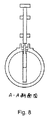
図7は、好適な三重スタブ同調器の一例を示す。三重スタブ同調器730は、2つの閉じた端部(入力部731、出力部732)と3つの同調スタブ740,750,760とを有する導波管を含む。各々の同調スタブ740,750,760は、当該導波管の壁にある対応の開口741,751,761の中に位置付けられ、これを動かすことで導波管の中へ延在する深さを変化させることができる。各々のスタブが導波管の中へ延在する深さを変化させることにより、インピーダンス調整器のインピーダンスが調整可能となる。このように、焼勺装置100,200のインピーダンスを、焼勺されるべき組織6のインピーダンスに整合させることができる。図7に示す三重スタブ同調器はその断面において円形(図8を参照)であるが、断面で長方形または正方形のものでもよい。
FIG. 7 shows an example of a suitable triple stub tuner. The
この実施例では、アクチュエータ(図7には示さず)、たとえばサーボモータまたは圧電素子により、各々の同調スタブ740,750,760の深さを制御する。このアクチュエータは、ユーザインターフェイス110および/または検出器により検出される大きさおよび位相に基づいてコントローラ101により制御される。
In this embodiment, the depth of each tuning
開口741,751,761は、図7に示すように導波管の同じ壁に、または異なる壁に設けられ得る。
The
図7に示す三重スタブ同調器の導波管730は、入力側および出力側を有する。入力側および出力側は、DC絶縁体770によって互いに隔離されたDC(直流)である。絶縁体770は、該当する周波数(マイクロ波放射線源で生成されるもの、たとえば14〜14.5GHz)を通過させる一方で直流を阻止する。任意の好適な絶縁体が使用可能であり、カプトン(登録商標)テープまたは、低損失・高電圧降伏の誘電材料の薄いシートたとえばPTFEまたはポリプロピレンが2つの可能な選択肢である。絶縁は最大6KVまで良好であるのが好ましい。
The triple
図7の例では、導波管730は2つの円筒体を含み、その一方は入力側に、他方は出力側に設けられ、一方が他方の中になるよう締りばめで嵌合され、絶縁体770で分離される。これら2つの円筒体を分離することで入力プローブ710および出力プローブ720の設置および調整を容易にすることが可能である。
In the example of FIG. 7, the
入力部710および出力部720は、導波管の中へ延在するEフィールドプローブの形態をとるのがよい。これは当該装置の残りの部分との接続のためのタイプNコネクタなどを有する。また、SMAコネクタを有するHフィールドプローブを用いてもよい。
The
導波管730は、図8に示すように断面が円筒形状であるのが好ましい。図8は、図7の線A−Aに沿った断面図であり、(横方向にずらした)調整可能な同調スタブ740を併せて示す。
The
図7では、各同調スタブは波長(当該放射線源により生成されるマイクロ波放射線の波長またはその帯域の平均)の8分の3の間隔をおいて配される。これに代わる実施例では、波長の8分の1または8分の5の間隔をおいて配されてもよい。当業者にはその他の好適な距離が明らかであろう。 In FIG. 7, the tuning stubs are spaced at three-eighths of the wavelength (the wavelength of the microwave radiation produced by the radiation source or the average of its band). In alternative embodiments, they may be spaced at 1/8 or 5/8 wavelength intervals. Other suitable distances will be apparent to those skilled in the art.
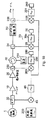
図21は、この発明の装置の代替的な一実施例を示し、同様の参照番号は上述と同様の要素を表わす。以下では新たな特徴点についてのみ説明を行なう。その他の特徴点は上に記載されている。マイクロ波放射線源1と増幅システム2との間には変調器1100およびフィルタ1120が設けられる。変調器1100は、これが接続されるコントローラ101からの変調信号1105によって制御される。変調器1100は、ON状態のときには、放射線源1からのマイクロ波放射線を変調して10kHz以上500MHz以下の範囲の周波数のパルスにする。変調器1100は柔軟で、上記範囲内の任意の周波数に変調可能なものとする。変調周波数はコントローラ101によって選択される。フィルタ1120は、変調器1100の出力部および増幅システム2の入力部に接続される。フィルタ1120はコントローラ101によって制御される。変調器1100がON状態のとき、フィルタ1120は、放射線源1からの高いマイクロ波周波数をフィルタ除去するように制御され、変調パルスの周波数を有する波形のみを通過させる。したがって、変調器1100がON状態のとき、10kHzから500MHzの範囲内の選択された周波数の放射線が当該装置の残りの部分へ出力されてプローブ5を通される。この周波数の放射線は特に切開に適したものである。変調器1100がOFF状態のとき、放射線源1からのマイクロ波放射線は変調されず、フィルタ1120はマイクロ波放射線を通過させるため、マイクロ波放射線が当該装置の残りの部分およびプローブ5に出力される。マイクロ波放射線は癌組織の焼勺に特に効果的である。変調器がON状態のときの変調周波数は、500kHzから30MHzの範囲内の周波数であることが好ましいが、なぜなら、これらの周波数が組織の切開にさらにより適していることがわかったからである。すなわちこれらの周波数は、神経刺激が生じないのに十分高いと同時に、熱マージンが最小限に抑えられるのに十分低いものだからである。
FIG. 21 shows an alternative embodiment of the apparatus of the present invention, wherein like reference numerals represent like elements as described above. Only the new feature points will be described below. Other features are described above. A
図21の実施例では、インピーダンス調整器として3スタブ同調器を用いている。スタブアクチュエータ1130は、スタブを制御することでインピーダンス調整器の出力インピーダンスを調整するように構成され、検出器230,250,260,280および200,220,240,270によって検出された電力および位相に基づいてコントローラ101で制御される。図21の実施例では、順方向マイクロ波放射線検出器および反射マイクロ波放射線検出器につき別個の局部発振器230,270を用いていることに注目されたい。
In the embodiment of FIG. 21, a 3-stub tuner is used as the impedance adjuster. The stub actuator 1130 is configured to adjust the output impedance of the impedance adjuster by controlling the stub and to adjust the power and phase detected by the
インピーダンス調整器50とプローブ5との間には位相調整器1110が設けられる。位相調整器1110はコントローラ101によって制御可能であり、これによって、インピーダンス調整器50の出力部とプローブ5の末端5aとの間の有効距離を、放射線源で生成されるマイクロ波放射線の波長を2で割ったものの倍数に等しくする。上述のように、これはインピーダンス整合および反射放射線の量の最小化に有利である。
A
当業者には明らかなように、上述の他の実施例のいずれにおいても、変調器および位相調整器の一方または両方を用いることができる。 As will be apparent to those skilled in the art, one or both of the modulator and the phase adjuster can be used in any of the other embodiments described above.
プローブ
焼勺装置のうち図1で包括的に100で示す部分は、多くの異なる種類のプローブ5とともに用いることができる。したがって、この装置は、接続されるプローブの種類を検出できるプローブ検出器を有することが好ましい。プローブには、プローブ検出器に識別信号を送信するための手段を設けることができる。プローブ検出器は、コントローラ101の一部とすることができる。コントローラは、プローブの種類や、検出されたプローブに関係する手続上の情報を表示するように構成され、またプローブの種類に従って電力レベルを変化させるように構成され得る。
The portion of the probe ablation device, generally designated 100 in FIG. 1, can be used with many different types of
以下、種々のプローブについて説明する。 Hereinafter, various probes will be described.
図9は、第1の導体900と、第2の導体910と、この両者の間にある誘電体920とを有する同軸プローブを示す。第1の導体900は細い細長の形状であり、銀または銅といった高導電性材料からなる。第2の導体920は第1の導体と同軸であり、外側の導電性鞘を形成する。誘電体はマイクロ波周波数について低損失の材料である。このプローブの特性インピーダンスは、第1の導体900の外径に対する第2の導体910の内径の比によって決定される。誘電体930は、導電性鞘920から外へ延在する。第1の導体900は、誘電体のさらに外へ延在し、組織6の貫入に用いることができる。図10は、図9の線B−Bに沿った断面図である。
FIG. 9 shows a coaxial probe having a
図9のプローブは複数のバラン930を有する。各々のバランは、外側の導体920の一部を取囲む第3の導体の形態をとる。各々のバラン930は、一端において第2の導体910と導通接触し、その長さのうち残りの部分については第2の導体から空気絶縁される。各々のバランの長さは、当該装置で用いられる波長の4分の1またはその奇数倍数とする。このバランは、第2の導体に沿った戻り電流を最小限に抑えるため、患者またはオペレータへのショックの危険性を最小限にしかつ健康な組織の加熱を減少または完全になくす上での助けとなる。
The probe of FIG. 9 has a plurality of
図11(a)は図9と類似のプローブを示すが、ここでは第1の導体900はその端部にもう1つの誘電体材料片935を有する(誘電体935は誘電体920と同じ材料であるのが好ましい)。第1の導体のうち、2つの誘電材料片920,935間にある部分936のみが露出される。
FIG. 11 (a) shows a probe similar to FIG. 9, but here the
図11(b)は、図9のプローブの端部の拡大図である。図11(c)は、図11(a)のプローブの端部の拡大図である。図11(d)は、第1の導体がその先端に誘電体935を有するが第1の誘電体片920が導電性鞘910より外へ延在しない例を示す。したがって、第1の導体のうち鞘910と第2の導体935との間にある部分が露出される。図11(e)は、誘電体920が鞘910の外へ延在せず、鞘910の端部付近の部分を取囲む金属製フェルール912を有するタングステン針911で第1の導体が終わっている例を示す。
FIG.11 (b) is an enlarged view of the edge part of the probe of FIG. FIG.11 (c) is an enlarged view of the edge part of the probe of Fig.11 (a). FIG. 11 (d) shows an example in which the first conductor has a dielectric 935 at its tip, but the first
図12は、組織6に挿入された同軸プローブを示す。同様の参照番号は図9と同様の要素を表わす。第2の導体910およびバラン930はトロカールによって取囲まれる。トロカールとは、身体内に挿入される管であってプローブまたはその他の装置(たとえば内視鏡)を挿入できるようにするものである。図13は図12の線C−Cに沿った断面図である。
FIG. 12 shows the coaxial probe inserted into the
図14は、プローブの代替的な一実施例であって、バランが第2の導体910と第3の導体930との間の吹付け誘電体932によって形成された例を示す。この目的に特に適した誘電体として、カミング社(Cumming Corporation)製の誘電体キャスト235Dがある。この態様で、バランを1つまたはそれ以上形成することができる。バランの長さは波長の4分の1またはその奇数倍数とする。
FIG. 14 shows an alternative embodiment of the probe where the balun is formed by a blowing dielectric 932 between the
これに代わる一実施例では、バランとして第3の導体930のない純粋誘電体バランを用いてもよい。当業者には適当な変更が明らかであろう。
In an alternative embodiment, a pure dielectric balun without the
図15は、波長の2分の1の深さおよび波長×1の幅を有する矩形の導波管プローブを示す。この構成の場合、Te21モードが伝播する。マイクロ波は、Eフィールドプローブ2002を介して焼勺プローブ6の中に結合される。Eフィールドプローブ2002は、導波管の中へ延在し、タイプNもしくはタイプKまたはSMAコネクタ2001を有する。導波管開口2003には低損失の誘電体が充填(装入)される。
FIG. 15 shows a rectangular waveguide probe having a half-wave depth and a wavelength × 1 width. In this configuration, Te 21 mode propagates. The microwave is coupled into the
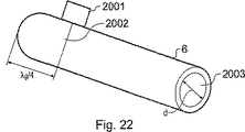
図22は、中心開口2003に固体の誘電材料を充填させた円筒形の導波管の焼勺プローブ6を示す。Eフィールドプローブが設けられ、SMA、NまたはKタイプのコネクタがその端部の1つからλ/4だけ離して設けられる。Hフィールドプローブを用いてもよい。
FIG. 22 shows a cylindrical
図14および図15の両方において、導波管ハウジング(壁)は、銅、真鍮またはアルミニウムから形成され、入力部(Eフィールドプローブ)は、導波管の一端から波長の4分の1だけ離して位置付けられる。 In both FIGS. 14 and 15, the waveguide housing (wall) is formed from copper, brass or aluminum, and the input (E field probe) is separated from one end of the waveguide by a quarter of the wavelength. Positioned.
図23は、末端にセラミック先端911を有する細長の焼勺プローブを示す。この先端は、マイクロ波放射線を組織内に送り届けるように構成される。セラミックとしては、マイクロ波周波数で相対比誘電率(εr)が6.5の低損失マイクロ波セラミック材料が用いられる。
FIG. 23 shows an elongated ablation probe having a
Claims (19)
マイクロ波放射線を生成するよう配置されたマイクロ波放射線源と、
焼勺されるべき組織の中へ前記マイクロ波放射線を向けるためのプローブと、
前記マイクロ波放射線源と前記プローブとの間に接続された反射放射線検出器と、
前記マイクロ波放射線源と前記プローブとの間に接続されたインピーダンス調整器とを備え、
前記マイクロ波放射線源によって生成された前記マイクロ波放射線は、5から60GHzの範囲の安定した出力周波数を有し、
前記装置は、前記マイクロ波放射線の周波数とは異なる周波数を有する信号を生成するよう配置された局部発振器を含み、
前記反射放射線検出器は、前記局部発振器に接続され、前記局部発振器からの信号と反射した放射線を比較することにより、反射して前記プローブを通り前記マイクロ波放射線源の方へ戻ってきたマイクロ波放射線の大きさおよび位相を検出するよう配置され、
前記インピーダンス調整器は、前記反射したマイクロ波放射線の検出された大きさおよび位相に基づいて制御可能である調整可能な複素インピーダンスを有する、装置。A tissue ablation device,
A microwave radiation source arranged to generate microwave radiation;
A probe for directing the pre-Symbol microwave radiation into tissue to be ablated,
A reflected radiation detector connected between the front Symbol microwave radiation source and the front Symbol probe,
Includes connected the impedance adjuster between the front Symbol microwave radiation source and the front Symbol probe,
Before SL before Symbol microwave radiation generated by the microwave radiation source has a stable output frequency in the range 60GHz from 5,
Before Symbol apparatus includes a local oscillator arranged to generate a signal having a frequency different from the frequency before Symbol microwave radiation,
Before SL reflected radiation detector is connected before Symbol local oscillator, by comparing the signal with the reflected radiation from the front Symbol local oscillator, reflected by the earlier SL as before Symbol microwave radiation source probe Arranged to detect the magnitude and phase of the returning microwave radiation,
Prior Symbol impedance adjuster has an adjustable complex impedance is controllable based on the previous SL reflected microwave radiation detected magnitude and phase, device.
Applications Claiming Priority (3)
| Application Number | Priority Date | Filing Date | Title |
|---|---|---|---|
| GB0227628A GB0227628D0 (en) | 2002-11-27 | 2002-11-27 | Miniature monopole antenna structures for minimally invasive therapeutic cancer treatment and use in intricate open surgery procedures |
| GB0227635A GB0227635D0 (en) | 2002-11-27 | 2002-11-27 | An invention of Technology electrosurgical system to enable effective treatment of cancerous growths manifested in vital organs of the human body |
| PCT/GB2003/005166 WO2004047659A2 (en) | 2002-11-27 | 2003-11-27 | Tissue ablation apparatus and method of ablating tissue |
Related Child Applications (1)
| Application Number | Title | Priority Date | Filing Date |
|---|---|---|---|
| JP2010000657A Division JP5081256B2 (en) | 2002-11-27 | 2010-01-05 | Tissue ablation device and method for cauterizing tissue |
Publications (3)
| Publication Number | Publication Date |
|---|---|
| JP2006507865A JP2006507865A (en) | 2006-03-09 |
| JP2006507865A5 JP2006507865A5 (en) | 2006-11-09 |
| JP4469723B2 true JP4469723B2 (en) | 2010-05-26 |
Family
ID=32395884
Family Applications (3)
| Application Number | Title | Priority Date | Filing Date |
|---|---|---|---|
| JP2004554703A Expired - Fee Related JP4469723B2 (en) | 2002-11-27 | 2003-11-27 | Tissue ablation device and method for cauterizing tissue |
| JP2010000657A Expired - Fee Related JP5081256B2 (en) | 2002-11-27 | 2010-01-05 | Tissue ablation device and method for cauterizing tissue |
| JP2012034788A Expired - Fee Related JP5292484B2 (en) | 2002-11-27 | 2012-02-21 | Tissue ablation device and method for cauterizing tissue |
Family Applications After (2)
| Application Number | Title | Priority Date | Filing Date |
|---|---|---|---|
| JP2010000657A Expired - Fee Related JP5081256B2 (en) | 2002-11-27 | 2010-01-05 | Tissue ablation device and method for cauterizing tissue |
| JP2012034788A Expired - Fee Related JP5292484B2 (en) | 2002-11-27 | 2012-02-21 | Tissue ablation device and method for cauterizing tissue |
Country Status (9)
| Country | Link |
|---|---|
| US (1) | US8768485B2 (en) |
| EP (3) | EP1723921B1 (en) |
| JP (3) | JP4469723B2 (en) |
| AT (3) | ATE398974T1 (en) |
| AU (1) | AU2003285538A1 (en) |
| CA (1) | CA2547587C (en) |
| DE (3) | DE60309744T2 (en) |
| ES (3) | ES2276133T3 (en) |
| WO (1) | WO2004047659A2 (en) |
Families Citing this family (180)
| Publication number | Priority date | Publication date | Assignee | Title |
|---|---|---|---|---|
| US5914613A (en) | 1996-08-08 | 1999-06-22 | Cascade Microtech, Inc. | Membrane probing system with local contact scrub |
| US6256882B1 (en) | 1998-07-14 | 2001-07-10 | Cascade Microtech, Inc. | Membrane probing system |
| US7137980B2 (en) | 1998-10-23 | 2006-11-21 | Sherwood Services Ag | Method and system for controlling output of RF medical generator |
| US6965226B2 (en) | 2000-09-05 | 2005-11-15 | Cascade Microtech, Inc. | Chuck for holding a device under test |
| US6914423B2 (en) | 2000-09-05 | 2005-07-05 | Cascade Microtech, Inc. | Probe station |
| DE10143173A1 (en) | 2000-12-04 | 2002-06-06 | Cascade Microtech Inc | Wafer probe has contact finger array with impedance matching network suitable for wide band |
| WO2003052435A1 (en) | 2001-08-21 | 2003-06-26 | Cascade Microtech, Inc. | Membrane probing system |
| US8043286B2 (en) | 2002-05-03 | 2011-10-25 | The Board Of Trustees Of The Leland Stanford Junior University | Method and apparatus for plasma-mediated thermo-electrical ablation |
| US6780178B2 (en) * | 2002-05-03 | 2004-08-24 | The Board Of Trustees Of The Leland Stanford Junior University | Method and apparatus for plasma-mediated thermo-electrical ablation |
| US7736361B2 (en) * | 2003-02-14 | 2010-06-15 | The Board Of Trustees Of The Leland Stamford Junior University | Electrosurgical system with uniformly enhanced electric field and minimal collateral damage |
| US7057404B2 (en) | 2003-05-23 | 2006-06-06 | Sharp Laboratories Of America, Inc. | Shielded probe for testing a device under test |
| US7492172B2 (en) | 2003-05-23 | 2009-02-17 | Cascade Microtech, Inc. | Chuck for holding a device under test |
| CA2529512A1 (en) * | 2003-06-18 | 2004-12-29 | The Board Of Trustees Of The Leland Stanford Junior University | Electro-adhesive tissue manipulator |
| GB2403148C2 (en) * | 2003-06-23 | 2013-02-13 | Microsulis Ltd | Radiation applicator |
| JP4232688B2 (en) * | 2003-07-28 | 2009-03-04 | 株式会社村田製作所 | Coaxial probe |
| DE202004021946U1 (en) | 2003-09-12 | 2013-05-29 | Vessix Vascular, Inc. | Selectable eccentric remodeling and / or ablation of atherosclerotic material |
| US7250626B2 (en) | 2003-10-22 | 2007-07-31 | Cascade Microtech, Inc. | Probe testing structure |
| EP1676108B1 (en) | 2003-10-23 | 2017-05-24 | Covidien AG | Thermocouple measurement circuit |
| US7396336B2 (en) | 2003-10-30 | 2008-07-08 | Sherwood Services Ag | Switched resonant ultrasonic power amplifier system |
| US7187188B2 (en) | 2003-12-24 | 2007-03-06 | Cascade Microtech, Inc. | Chuck with integrated wafer support |
| GB2425844B (en) | 2003-12-24 | 2007-07-11 | Cascade Microtech Inc | Active wafer probe |
| US8989840B2 (en) * | 2004-03-30 | 2015-03-24 | Medtronic, Inc. | Lead electrode for use in an MRI-safe implantable medical device |
| US7877150B2 (en) | 2004-03-30 | 2011-01-25 | Medtronic, Inc. | Lead electrode for use in an MRI-safe implantable medical device |
| US7844343B2 (en) | 2004-03-30 | 2010-11-30 | Medtronic, Inc. | MRI-safe implantable medical device |
| US9155877B2 (en) | 2004-03-30 | 2015-10-13 | Medtronic, Inc. | Lead electrode for use in an MRI-safe implantable medical device |
| US7844344B2 (en) * | 2004-03-30 | 2010-11-30 | Medtronic, Inc. | MRI-safe implantable lead |
| US20070055224A1 (en) * | 2004-04-29 | 2007-03-08 | Lee Fred T Jr | Intralumenal microwave device |
| DE602005024952D1 (en) | 2004-05-26 | 2011-01-05 | Medical Device Innovations Ltd | TISSUE DETECTION AND ABLATION DEVICE |
| US8396548B2 (en) | 2008-11-14 | 2013-03-12 | Vessix Vascular, Inc. | Selective drug delivery in a lumen |
| US7420381B2 (en) | 2004-09-13 | 2008-09-02 | Cascade Microtech, Inc. | Double sided probing structures |
| US9215788B2 (en) | 2005-01-18 | 2015-12-15 | Alma Lasers Ltd. | System and method for treating biological tissue with a plasma gas discharge |
| KR100895939B1 (en) | 2005-01-18 | 2009-05-07 | 알마 레이저스 엘티디 | Improved system and method for heating biological tissue via rf energy |
| US7656172B2 (en) | 2005-01-31 | 2010-02-02 | Cascade Microtech, Inc. | System for testing semiconductors |
| US7535247B2 (en) | 2005-01-31 | 2009-05-19 | Cascade Microtech, Inc. | Interface for testing semiconductors |
| US8280526B2 (en) | 2005-02-01 | 2012-10-02 | Medtronic, Inc. | Extensible implantable medical lead |
| ES2565342T3 (en) | 2005-03-28 | 2016-04-04 | Vessix Vascular, Inc. | Intraluminal electrical characterization of tissue and regulated RF energy for selective treatment of atheroma and other target tissues |
| US7853332B2 (en) | 2005-04-29 | 2010-12-14 | Medtronic, Inc. | Lead electrode for use in an MRI-safe implantable medical device |
| US8027736B2 (en) | 2005-04-29 | 2011-09-27 | Medtronic, Inc. | Lead electrode for use in an MRI-safe implantable medical device |
| WO2006138382A2 (en) * | 2005-06-14 | 2006-12-28 | Micrablate, Llc | Microwave tissue resection tool |
| US20100060231A1 (en) * | 2006-01-05 | 2010-03-11 | Tpl, Inc. | Method and Apparatus for Energy Harvesting and/or Generation, Storage, and Delivery |
| US7692411B2 (en) * | 2006-01-05 | 2010-04-06 | Tpl, Inc. | System for energy harvesting and/or generation, storage, and delivery |
| US8672932B2 (en) | 2006-03-24 | 2014-03-18 | Neuwave Medical, Inc. | Center fed dipole for use with tissue ablation systems, devices and methods |
| US20070288079A1 (en) * | 2006-03-24 | 2007-12-13 | Micrablate | Energy delivery system and uses thereof |
| EP1998698B1 (en) | 2006-03-24 | 2020-12-23 | Neuwave Medical, Inc. | Transmission line with heat transfer ability |
| US7764072B2 (en) | 2006-06-12 | 2010-07-27 | Cascade Microtech, Inc. | Differential signal probing system |
| US7403028B2 (en) | 2006-06-12 | 2008-07-22 | Cascade Microtech, Inc. | Test structure and probe for differential signals |
| US7723999B2 (en) | 2006-06-12 | 2010-05-25 | Cascade Microtech, Inc. | Calibration structures for differential signal probing |
| JP4611247B2 (en) * | 2006-06-14 | 2011-01-12 | オリンパスメディカルシステムズ株式会社 | High frequency treatment tool |
| US11389235B2 (en) | 2006-07-14 | 2022-07-19 | Neuwave Medical, Inc. | Energy delivery systems and uses thereof |
| US10376314B2 (en) * | 2006-07-14 | 2019-08-13 | Neuwave Medical, Inc. | Energy delivery systems and uses thereof |
| WO2008034103A2 (en) | 2006-09-14 | 2008-03-20 | Lazure Technologies, Llc | Device and method for destruction of cancer cells |
| GB0620058D0 (en) | 2006-10-10 | 2006-11-22 | Medical Device Innovations Ltd | Tissue measurement and ablation antenna |
| US9050115B2 (en) | 2006-10-10 | 2015-06-09 | Creo Medical Limited | Surgical antenna |
| CN102961184B (en) | 2006-10-10 | 2016-08-10 | 医疗设备创新有限公司 | Utilize microwave radiation to treat the device of tissue and antenna calibration system and method |
| GB0620063D0 (en) | 2006-10-10 | 2006-11-22 | Medical Device Innovations Ltd | Needle structure and method of performing needle biopsies |
| EP2954868A1 (en) | 2006-10-18 | 2015-12-16 | Vessix Vascular, Inc. | Tuned rf energy and electrical tissue characterization for selective treatment of target tissues |
| ES2560006T3 (en) | 2006-10-18 | 2016-02-17 | Vessix Vascular, Inc. | Induction of desirable temperature effects on body tissue |
| JP5559539B2 (en) | 2006-10-18 | 2014-07-23 | べシックス・バスキュラー・インコーポレイテッド | System that induces desirable temperature effects on body tissue |
| MX2009004704A (en) * | 2006-11-02 | 2009-09-21 | Peak Surgical Inc | Electric plasma-mediated cutting and coagulation of tissue and surgical apparatus. |
| GB0624584D0 (en) * | 2006-12-08 | 2007-01-17 | Medical Device Innovations Ltd | Skin treatment apparatus and method |
| GB0624658D0 (en) | 2006-12-11 | 2007-01-17 | Medical Device Innovations Ltd | Electrosurgical ablation apparatus and a method of ablating biological tissue |
| US9044593B2 (en) | 2007-02-14 | 2015-06-02 | Medtronic, Inc. | Discontinuous conductive filler polymer-matrix composites for electromagnetic shielding |
| US10537730B2 (en) | 2007-02-14 | 2020-01-21 | Medtronic, Inc. | Continuous conductive materials for electromagnetic shielding |
| GB0704650D0 (en) | 2007-03-09 | 2007-04-18 | Medical Device Innovations Ltd | Tissue classifying apparatus |
| US8496653B2 (en) | 2007-04-23 | 2013-07-30 | Boston Scientific Scimed, Inc. | Thrombus removal |
| US8483842B2 (en) | 2007-04-25 | 2013-07-09 | Medtronic, Inc. | Lead or lead extension having a conductive body and conductive body contact |
| US9861424B2 (en) * | 2007-07-11 | 2018-01-09 | Covidien Lp | Measurement and control systems and methods for electrosurgical procedures |
| US7876114B2 (en) | 2007-08-08 | 2011-01-25 | Cascade Microtech, Inc. | Differential waveguide probe |
| WO2009036457A1 (en) | 2007-09-14 | 2009-03-19 | Lazure Technologies, Llc | Multi-layer electrode ablation probe and related methods |
| US8880195B2 (en) | 2007-09-14 | 2014-11-04 | Lazure Technologies, Llc | Transurethral systems and methods for ablation treatment of prostate tissue |
| WO2009036459A1 (en) * | 2007-09-14 | 2009-03-19 | Lazure Technologies, Llc | Multi-tine probe and treatment by activation of opposing tines |
| GB0718721D0 (en) | 2007-09-25 | 2007-11-07 | Medical Device Innovations Ltd | Surgical resection apparatus |
| CN104174049B (en) | 2007-11-06 | 2017-03-01 | 克里奥医药有限公司 | Adjustable applicator component and plasma body sterilizing equipment |
| US9037263B2 (en) | 2008-03-12 | 2015-05-19 | Medtronic, Inc. | System and method for implantable medical device lead shielding |
| US20100100093A1 (en) * | 2008-09-16 | 2010-04-22 | Lazure Technologies, Llc. | System and method for controlled tissue heating for destruction of cancerous cells |
| US8242782B2 (en) | 2008-09-30 | 2012-08-14 | Vivant Medical, Inc. | Microwave ablation generator control system |
| US8287527B2 (en) * | 2008-09-30 | 2012-10-16 | Vivant Medical, Inc. | Microwave system calibration apparatus and method of use |
| US20100082083A1 (en) * | 2008-09-30 | 2010-04-01 | Brannan Joseph D | Microwave system tuner |
| US8346370B2 (en) * | 2008-09-30 | 2013-01-01 | Vivant Medical, Inc. | Delivered energy generator for microwave ablation |
| US8248075B2 (en) * | 2008-09-30 | 2012-08-21 | Vivant Medical, Inc. | System, apparatus and method for dissipating standing wave in a microwave delivery system |
| US7888957B2 (en) | 2008-10-06 | 2011-02-15 | Cascade Microtech, Inc. | Probing apparatus with impedance optimized interface |
| EP2355737B1 (en) | 2008-11-17 | 2021-08-11 | Boston Scientific Scimed, Inc. | Selective accumulation of energy without knowledge of tissue topography |
| US8410806B2 (en) | 2008-11-21 | 2013-04-02 | Cascade Microtech, Inc. | Replaceable coupon for a probing apparatus |
| US8319503B2 (en) | 2008-11-24 | 2012-11-27 | Cascade Microtech, Inc. | Test apparatus for measuring a characteristic of a device under test |
| US8137345B2 (en) | 2009-01-05 | 2012-03-20 | Peak Surgical, Inc. | Electrosurgical devices for tonsillectomy and adenoidectomy |
| US8262652B2 (en) | 2009-01-12 | 2012-09-11 | Tyco Healthcare Group Lp | Imaginary impedance process monitoring and intelligent shut-off |
| US8989855B2 (en) * | 2009-01-30 | 2015-03-24 | Medtronic Xomed, Inc. | Nerve monitoring during electrosurgery |
| GB2467604B (en) | 2009-02-10 | 2013-08-28 | Univ Bangor | Skin treatment apparatus and method |
| US8728139B2 (en) | 2009-04-16 | 2014-05-20 | Lazure Technologies, Llc | System and method for energy delivery to a tissue using an electrode array |
| EP2537554B1 (en) | 2009-04-30 | 2015-10-07 | Medtronic, Inc. | Termination of a shield within an implantable medical lead |
| US8551096B2 (en) | 2009-05-13 | 2013-10-08 | Boston Scientific Scimed, Inc. | Directional delivery of energy and bioactives |
| US8246615B2 (en) * | 2009-05-19 | 2012-08-21 | Vivant Medical, Inc. | Tissue impedance measurement using a secondary frequency |
| WO2011004561A1 (en) * | 2009-07-10 | 2011-01-13 | パナソニック株式会社 | Microwave heating device and microwave heating control method |
| GB2472972A (en) | 2009-07-20 | 2011-03-02 | Microoncology Ltd | A microwave antenna |
| GB2472012A (en) | 2009-07-20 | 2011-01-26 | Microoncology Ltd | Microwave antenna with flat paddle shape |
| JP5914332B2 (en) | 2009-07-28 | 2016-05-11 | ニューウェーブ メディカル, インコーポレイテッドNeuwave Medical, Inc. | Ablation device |
| US8328800B2 (en) * | 2009-08-05 | 2012-12-11 | Vivant Medical, Inc. | Directive window ablation antenna with dielectric loading |
| US8328799B2 (en) * | 2009-08-05 | 2012-12-11 | Vivant Medical, Inc. | Electrosurgical devices having dielectric loaded coaxial aperture with distally positioned resonant structure |
| AU2014202676B2 (en) * | 2009-08-05 | 2015-05-07 | Covidien Lp | Directive window ablation antenna with dielectric loading |
| US8328801B2 (en) * | 2009-08-17 | 2012-12-11 | Vivant Medical, Inc. | Surface ablation antenna with dielectric loading |
| US8906007B2 (en) | 2009-09-28 | 2014-12-09 | Covidien Lp | Electrosurgical devices, directional reflector assemblies coupleable thereto, and electrosurgical systems including same |
| US8469953B2 (en) | 2009-11-16 | 2013-06-25 | Covidien Lp | Twin sealing chamber hub |
| US8394092B2 (en) * | 2009-11-17 | 2013-03-12 | Vivant Medical, Inc. | Electromagnetic energy delivery devices including an energy applicator array and electrosurgical systems including same |
| WO2011061486A1 (en) * | 2009-11-18 | 2011-05-26 | Emblation Limited | A microwave apparatus and method |
| US8491579B2 (en) * | 2010-02-05 | 2013-07-23 | Covidien Lp | Electrosurgical devices with choke shorted to biological tissue |
| US8968288B2 (en) * | 2010-02-19 | 2015-03-03 | Covidien Lp | Ablation devices with dual operating frequencies, systems including same, and methods of adjusting ablation volume using same |
| JP2013523318A (en) | 2010-04-09 | 2013-06-17 | べシックス・バスキュラー・インコーポレイテッド | Power generation and control equipment for tissue treatment |
| US9526911B1 (en) | 2010-04-27 | 2016-12-27 | Lazure Scientific, Inc. | Immune mediated cancer cell destruction, systems and methods |
| EP3804651A1 (en) | 2010-05-03 | 2021-04-14 | Neuwave Medical, Inc. | Energy delivery systems |
| US9561076B2 (en) * | 2010-05-11 | 2017-02-07 | Covidien Lp | Electrosurgical devices with balun structure for air exposure of antenna radiating section and method of directing energy to tissue using same |
| US20120116486A1 (en) | 2010-10-25 | 2012-05-10 | Medtronic Ardian Luxembourg S.A.R.L. | Microwave catheter apparatuses, systems, and methods for renal neuromodulation |
| US9005193B2 (en) * | 2010-11-08 | 2015-04-14 | Biosense Webster (Israel) Ltd. | Multichannel ablation with frequency differentiation |
| US9005192B2 (en) | 2010-11-08 | 2015-04-14 | Biosense Webster (Israel) Ltd. | Simultaneous ablation by multiple electrodes |
| GB201021032D0 (en) | 2010-12-10 | 2011-01-26 | Creo Medical Ltd | Electrosurgical apparatus |
| US9011421B2 (en) | 2011-01-05 | 2015-04-21 | Covidien Lp | Energy-delivery devices with flexible fluid-cooled shaft, inflow/outflow junctions suitable for use with same, and systems including same |
| US8932281B2 (en) * | 2011-01-05 | 2015-01-13 | Covidien Lp | Energy-delivery devices with flexible fluid-cooled shaft, inflow/outflow junctions suitable for use with same, and systems including same |
| US9017319B2 (en) | 2011-01-05 | 2015-04-28 | Covidien Lp | Energy-delivery devices with flexible fluid-cooled shaft, inflow/outflow junctions suitable for use with same, and systems including same |
| US9770294B2 (en) | 2011-01-05 | 2017-09-26 | Covidien Lp | Energy-delivery devices with flexible fluid-cooled shaft, inflow/outflow junctions suitable for use with same, and systems including same |
| WO2012170364A1 (en) | 2011-06-10 | 2012-12-13 | Medtronic, Inc. | Wire electrode devices for tonsillectomy and adenoidectomy |
| US8968297B2 (en) | 2011-07-19 | 2015-03-03 | Covidien Lp | Microwave and RF ablation system and related method for dynamic impedance matching |
| US9028482B2 (en) | 2011-07-19 | 2015-05-12 | Covidien Lp | Microwave and RF ablation system and related method for dynamic impedance matching |
| US9192422B2 (en) | 2011-07-19 | 2015-11-24 | Covidien Lp | System and method of matching impedances of an electrosurgical generator and/or a microwave generator |
| US9023025B2 (en) | 2011-09-20 | 2015-05-05 | Covidien Lp | Handheld medical devices including microwave amplifier unit at device handle |
| US8745846B2 (en) | 2011-09-20 | 2014-06-10 | Covidien Lp | Method of manufacturing handheld medical devices including microwave amplifier unit |
| US9039692B2 (en) | 2011-09-20 | 2015-05-26 | Covidien Lp | Handheld medical devices including microwave amplifier unit at device handle |
| US9039693B2 (en) | 2011-09-20 | 2015-05-26 | Covidien Lp | Handheld medical devices including microwave amplifier unit at device handle |
| US9033970B2 (en) | 2011-09-20 | 2015-05-19 | Covidien Lp | Handheld medical devices including microwave amplifier unit at device handle |
| JP5979845B2 (en) * | 2011-10-25 | 2016-08-31 | 株式会社 オリエントマイクロウェーブ | Microwave surgical device and device including microwave surgical device |
| JP2015503963A (en) | 2011-12-21 | 2015-02-05 | ニューウェーブ メディカル, インコーポレイテッドNeuwave Medical, Inc. | Energy supply system and method of use thereof |
| US8943744B2 (en) * | 2012-02-17 | 2015-02-03 | Nathaniel L. Cohen | Apparatus for using microwave energy for insect and pest control and methods thereof |
| US8968290B2 (en) * | 2012-03-14 | 2015-03-03 | Covidien Lp | Microwave ablation generator control system |
| US9463317B2 (en) | 2012-04-19 | 2016-10-11 | Medtronic, Inc. | Paired medical lead bodies with braided conductive shields having different physical parameter values |
| PL2676624T3 (en) * | 2012-06-18 | 2017-06-30 | Erbe Elektromedizin Gmbh | High frequency surgical device |
| US9529025B2 (en) | 2012-06-29 | 2016-12-27 | Covidien Lp | Systems and methods for measuring the frequency of signals generated by high frequency medical devices |
| US9044254B2 (en) | 2012-08-07 | 2015-06-02 | Covidien Lp | Microwave ablation catheter and method of utilizing the same |
| GB2506377A (en) * | 2012-09-27 | 2014-04-02 | Creo Medical Ltd | Electrosurgical apparatus comprising an RF generator, microwave generator, combining circuit and waveguide isolator |
| US9498276B2 (en) | 2013-03-15 | 2016-11-22 | Covidien Lp | Systems and methods for narrowband real impedance control in electrosurgery |
| JP6363169B2 (en) * | 2013-03-29 | 2018-07-25 | コビディエン エルピー | Step-down coaxial microwave ablation applicator and method for manufacturing the same |
| US10470256B2 (en) * | 2013-04-16 | 2019-11-05 | Applied Materials, Inc. | Method and apparatus for controlled broadband microwave heating |
| US9872719B2 (en) | 2013-07-24 | 2018-01-23 | Covidien Lp | Systems and methods for generating electrosurgical energy using a multistage power converter |
| US9636165B2 (en) | 2013-07-29 | 2017-05-02 | Covidien Lp | Systems and methods for measuring tissue impedance through an electrosurgical cable |
| WO2015020617A1 (en) * | 2013-08-06 | 2015-02-12 | Agricultural Research Development Agency (Public Organization) | A dielectric heating system for controlling mold, moisture, and/or pests such as weevils in agricultural products |
| US9839469B2 (en) | 2013-09-24 | 2017-12-12 | Covidien Lp | Systems and methods for improving efficiency of electrosurgical generators |
| US9770283B2 (en) | 2013-09-24 | 2017-09-26 | Covidien Lp | Systems and methods for improving efficiency of electrosurgical generators |
| GB201321710D0 (en) * | 2013-12-09 | 2014-01-22 | Creo Medical Ltd | Electrosurgical apparatus |
| US9993638B2 (en) | 2013-12-14 | 2018-06-12 | Medtronic, Inc. | Devices, systems and methods to reduce coupling of a shield and a conductor within an implantable medical lead |
| WO2015120278A1 (en) * | 2014-02-06 | 2015-08-13 | Meridian Medical Systems, Llc | System for identifying tissue characteristics or properties utilizing radiometric sensing |
| US20170172655A1 (en) * | 2014-03-21 | 2017-06-22 | Steven D. Schwaitzberg | System and method for treatment of barrett's esophagus incorporating radiometric sensing |
| US10368404B2 (en) | 2014-03-21 | 2019-07-30 | Whirlpool Corporation | Solid-state microwave device |
| WO2016014427A1 (en) | 2014-07-23 | 2016-01-28 | Medtronic, Inc. | Methods of shielding implantable medical leads and implantable medical lead extensions |
| US10155111B2 (en) | 2014-07-24 | 2018-12-18 | Medtronic, Inc. | Methods of shielding implantable medical leads and implantable medical lead extensions |
| US10624697B2 (en) * | 2014-08-26 | 2020-04-21 | Covidien Lp | Microwave ablation system |
| US10925684B2 (en) | 2015-05-12 | 2021-02-23 | Navix International Limited | Contact quality assessment by dielectric property analysis |
| EP3294179B1 (en) | 2015-05-12 | 2024-04-17 | Navix International Limited | Lesion assessment by dielectric property analysis |
| WO2016181320A1 (en) | 2015-05-12 | 2016-11-17 | Navix International Limited | Fiducial marking for image-electromagnetic field registration |
| US10278616B2 (en) | 2015-05-12 | 2019-05-07 | Navix International Limited | Systems and methods for tracking an intrabody catheter |
| GB2539494A (en) | 2015-06-19 | 2016-12-21 | Creo Medical Ltd | Electrosurgical Instrument |
| EP3367942B1 (en) | 2015-10-26 | 2021-01-20 | Neuwave Medical, Inc. | Energy delivery systems |
| GB2550537B (en) * | 2016-02-11 | 2018-04-04 | Gyrus Medical Ltd | Microwave ablation antenna assemblies |
| US10813692B2 (en) | 2016-02-29 | 2020-10-27 | Covidien Lp | 90-degree interlocking geometry for introducer for facilitating deployment of microwave radiating catheter |
| WO2017165562A1 (en) * | 2016-03-22 | 2017-09-28 | Microcube, Llc | Methods and devices for energy delivery and therapy |
| BR112018071018A2 (en) | 2016-04-15 | 2019-02-12 | Neuwave Medical, Inc. | energy application systems and methods |
| GB2552169A (en) | 2016-07-11 | 2018-01-17 | Creo Medical Ltd | Electrosurgical generator |
| EP3484362A1 (en) | 2016-07-14 | 2019-05-22 | Navix International Limited | Characteristic track catheter navigation |
| US10376309B2 (en) | 2016-08-02 | 2019-08-13 | Covidien Lp | Ablation cable assemblies and a method of manufacturing the same |
| US11065053B2 (en) | 2016-08-02 | 2021-07-20 | Covidien Lp | Ablation cable assemblies and a method of manufacturing the same |
| US11197715B2 (en) | 2016-08-02 | 2021-12-14 | Covidien Lp | Ablation cable assemblies and a method of manufacturing the same |
| US11331029B2 (en) | 2016-11-16 | 2022-05-17 | Navix International Limited | Esophagus position detection by electrical mapping |
| US11284813B2 (en) | 2016-11-16 | 2022-03-29 | Navix International Limited | Real-time display of tissue deformation by interactions with an intra-body probe |
| EP3541313B1 (en) | 2016-11-16 | 2023-05-10 | Navix International Limited | Estimators for ablation effectiveness |
| WO2018092059A1 (en) | 2016-11-16 | 2018-05-24 | Navix International Limited | Tissue model dynamic visual rendering |
| WO2018092063A1 (en) | 2016-11-16 | 2018-05-24 | Navix International Limited | Real-time display of treatment-related tissue changes using virtual material |
| US10321878B2 (en) | 2016-12-22 | 2019-06-18 | Biosense Webster (Israel) Ltd. | Pulmonary vein display in two dimensions |
| US11282191B2 (en) | 2017-01-12 | 2022-03-22 | Navix International Limited | Flattened view for intra-lumenal navigation |
| US11842456B2 (en) | 2017-01-12 | 2023-12-12 | Navix International Limited | Flattened view for intra-lumenal navigation |
| GB2569811A (en) * | 2017-12-27 | 2019-07-03 | Creo Medical Ltd | Electrosurgical apparatus |
| US11672596B2 (en) | 2018-02-26 | 2023-06-13 | Neuwave Medical, Inc. | Energy delivery devices with flexible and adjustable tips |
| JP2019154867A (en) * | 2018-03-14 | 2019-09-19 | 華郎 前田 | Microwave therapy device and microwave therapeutic system |
| US11832879B2 (en) | 2019-03-08 | 2023-12-05 | Neuwave Medical, Inc. | Systems and methods for energy delivery |
| CN113040898A (en) * | 2021-03-08 | 2021-06-29 | 南京航空航天大学 | Double-frequency microwave ablation instrument |
Family Cites Families (107)
| Publication number | Priority date | Publication date | Assignee | Title |
|---|---|---|---|---|
| US663622A (en) * | 1899-04-12 | 1900-12-11 | Thomas Ryan | Leaf-turner. |
| GB1126901A (en) | 1964-06-19 | 1968-09-11 | British Ropes Ltd | Improvements in or relating to the manufacture of wire ropes or strands |
| DE2504280C3 (en) * | 1975-02-01 | 1980-08-28 | Hans Heinrich Prof. Dr. 8035 Gauting Meinke | Device for cutting and / or coagulating human tissue with high frequency current |
| US4488559A (en) * | 1981-06-30 | 1984-12-18 | University Of Utah | Apparatus and method for measuring lung water content |
| US4397313A (en) * | 1981-08-03 | 1983-08-09 | Clini-Therm Corporation | Multiple microwave applicator system and method for microwave hyperthermia treatment |
| JPS58173540A (en) * | 1982-04-03 | 1983-10-12 | 銭谷 利男 | Operation by microwave |
| US4571552A (en) * | 1983-11-07 | 1986-02-18 | Raytheon Company | Phase-locked magnetron system |
| US4815479A (en) | 1986-08-13 | 1989-03-28 | M/A Com, Inc. | Hyperthermia treatment method and apparatus |
| DE3637549A1 (en) | 1986-11-04 | 1988-05-11 | Hans Dr Med Rosenberger | Measuring device for testing the dielectric properties of biological tissues |
| US4825880A (en) * | 1987-06-19 | 1989-05-02 | The Regents Of The University Of California | Implantable helical coil microwave antenna |
| FR2617723A1 (en) | 1987-07-07 | 1989-01-13 | Odam Sa | Method and apparatus for treating pathological conditions by stimulation of acupuncture points |
| US5524281A (en) * | 1988-03-31 | 1996-06-04 | Wiltron Company | Apparatus and method for measuring the phase and magnitude of microwave signals |
| DE3815835A1 (en) * | 1988-05-09 | 1989-11-23 | Flachenecker Gerhard | HIGH FREQUENCY GENERATOR FOR TISSUE CUTTING AND COAGULATION IN HIGH FREQUENCY SURGERY |
| WO1989011311A1 (en) * | 1988-05-18 | 1989-11-30 | Kasevich Associates, Inc. | Microwave balloon angioplasty |
| JPH02182272A (en) * | 1988-12-14 | 1990-07-16 | Microthermia Technol Inc | Apparatus and method for breaking cell of tumor or the like |
| US4976711A (en) * | 1989-04-13 | 1990-12-11 | Everest Medical Corporation | Ablation catheter with selectively deployable electrodes |
| US5057105A (en) * | 1989-08-28 | 1991-10-15 | The University Of Kansas Med Center | Hot tip catheter assembly |
| US5113065A (en) * | 1990-09-10 | 1992-05-12 | United Technologies Corporation | Heterodyne circular photodetector array in a tracking system |
| WO1992004934A1 (en) * | 1990-09-14 | 1992-04-02 | American Medical Systems, Inc. | Combined hyperthermia and dilation catheter |
| DE4126608A1 (en) * | 1991-08-12 | 1993-02-18 | Fastenmeier Karl | ARRANGEMENT FOR CUTTING ORGANIC TISSUE WITH HIGH-FREQUENCY CURRENT |
| WO1993003677A2 (en) * | 1991-08-12 | 1993-03-04 | Karl Storz Gmbh & Co. | Surgical high-frequency generator for cutting tissues |
| US5557283A (en) * | 1991-08-30 | 1996-09-17 | Sheen; David M. | Real-time wideband holographic surveillance system |
| JP2828817B2 (en) * | 1991-12-05 | 1998-11-25 | 日本商事株式会社 | Surgery switching device |
| WO1993020768A1 (en) * | 1992-04-13 | 1993-10-28 | Ep Technologies, Inc. | Steerable microwave antenna systems for cardiac ablation |
| US5720718A (en) * | 1992-08-12 | 1998-02-24 | Vidamed, Inc. | Medical probe apparatus with enhanced RF, resistance heating, and microwave ablation capabilities |
| US5227730A (en) * | 1992-09-14 | 1993-07-13 | Kdc Technology Corp. | Microwave needle dielectric sensors |
| US5364392A (en) * | 1993-05-14 | 1994-11-15 | Fidus Medical Technology Corporation | Microwave ablation catheter system with impedance matching tuner and method |
| US5405346A (en) * | 1993-05-14 | 1995-04-11 | Fidus Medical Technology Corporation | Tunable microwave ablation catheter |
| US5693082A (en) * | 1993-05-14 | 1997-12-02 | Fidus Medical Technology Corporation | Tunable microwave ablation catheter system and method |
| US5391199A (en) * | 1993-07-20 | 1995-02-21 | Biosense, Inc. | Apparatus and method for treating cardiac arrhythmias |
| GB9315473D0 (en) * | 1993-07-27 | 1993-09-08 | Chemring Ltd | Treatment apparatus |
| US5507791A (en) * | 1993-08-31 | 1996-04-16 | Sit'ko; Sergei P. | Microwave resonance therapy |
| AU7661494A (en) | 1993-09-21 | 1995-04-10 | Alcan International Limited | Aluminium sheet with rough surface |
| US5518861A (en) * | 1994-04-26 | 1996-05-21 | E. I. Du Pont De Nemours And Company | Element and process for laser-induced ablative transfer |
| US6002968A (en) | 1994-06-24 | 1999-12-14 | Vidacare, Inc. | Uterine treatment apparatus |
| US5704355A (en) * | 1994-07-01 | 1998-01-06 | Bridges; Jack E. | Non-invasive system for breast cancer detection |
| US5829437A (en) * | 1994-07-01 | 1998-11-03 | Interstitial, Inc. | Microwave method and system to detect and locate cancers in heterogenous tissues |
| US6421550B1 (en) * | 1994-07-01 | 2002-07-16 | Interstitial, L.L.C. | Microwave discrimination between malignant and benign breast tumors |
| US5509916A (en) * | 1994-08-12 | 1996-04-23 | Valleylab Inc. | Laser-assisted electrosurgery system |
| FI98420C (en) * | 1995-01-24 | 1997-06-10 | Nokia Mobile Phones Ltd | Method and connection to generate a modulated signal in a transmitter / receiver |
| US5519359A (en) * | 1995-04-26 | 1996-05-21 | Westinghouse Electric Corp. | Microwave oscillator with loop frequency conversion to and signal amplification at an intermediate frequency |
| US5755753A (en) * | 1995-05-05 | 1998-05-26 | Thermage, Inc. | Method for controlled contraction of collagen tissue |
| US6345194B1 (en) * | 1995-06-06 | 2002-02-05 | Robert S. Nelson | Enhanced high resolution breast imaging device and method utilizing non-ionizing radiation of narrow spectral bandwidth |
| AU714014B2 (en) * | 1995-06-28 | 1999-12-16 | B & H Manufacturing Company, Inc. | Applying stretch labels |
| US6496738B2 (en) * | 1995-09-06 | 2002-12-17 | Kenneth L. Carr | Dual frequency microwave heating apparatus |
| US6350276B1 (en) * | 1996-01-05 | 2002-02-26 | Thermage, Inc. | Tissue remodeling apparatus containing cooling fluid |
| US6289249B1 (en) * | 1996-04-17 | 2001-09-11 | The United States Of America As Represented By The Administrator Of The National Aeronautics And Space Administration | Transcatheter microwave antenna |
| WO1997043971A2 (en) * | 1996-05-22 | 1997-11-27 | Somnus Medical Technologies, Inc. | Method and apparatus for ablating turbinates |
| US5737384A (en) * | 1996-10-04 | 1998-04-07 | Massachusetts Institute Of Technology | X-ray needle providing heating with microwave energy |
| US5810803A (en) * | 1996-10-16 | 1998-09-22 | Fidus Medical Technology Corporation | Conformal positioning assembly for microwave ablation catheter |
| US5906609A (en) * | 1997-02-05 | 1999-05-25 | Sahar Technologies | Method for delivering energy within continuous outline |
| KR100247005B1 (en) * | 1997-05-19 | 2000-04-01 | 윤종용 | Impedance matching apparatus which is controled by electric signal in rf amplifier |
| US6414562B1 (en) * | 1997-05-27 | 2002-07-02 | Motorola, Inc. | Circuit and method for impedance matching |
| JP3245815B2 (en) * | 1997-07-02 | 2002-01-15 | 株式会社日本エム・ディ・エム | Biological tissue processing equipment using high frequency |
| US6104959A (en) | 1997-07-31 | 2000-08-15 | Microwave Medical Corp. | Method and apparatus for treating subcutaneous histological features |
| DE19737482A1 (en) * | 1997-08-28 | 1999-03-04 | Alsthom Cge Alcatel | Process for optical transmission over an optical fiber network, and optical transmission network |
| US20020158212A1 (en) * | 1998-04-17 | 2002-10-31 | French Todd E. | Apparatus and methods for time-resolved optical spectroscopy |
| US6047215A (en) * | 1998-03-06 | 2000-04-04 | Sonique Surgical Systems, Inc. | Method and apparatus for electromagnetically assisted liposuction |
| US6635055B1 (en) * | 1998-05-06 | 2003-10-21 | Microsulis Plc | Microwave applicator for endometrial ablation |
| JP3919947B2 (en) | 1998-07-09 | 2007-05-30 | アルフレッサファーマ株式会社 | Microwave surgical electrode device |
| US6251128B1 (en) * | 1998-09-01 | 2001-06-26 | Fidus Medical Technology Corporation | Microwave ablation catheter with loop configuration |
| US6016811A (en) * | 1998-09-01 | 2000-01-25 | Fidus Medical Technology Corporation | Method of using a microwave ablation catheter with a loop configuration |
| US6391026B1 (en) * | 1998-09-18 | 2002-05-21 | Pro Duct Health, Inc. | Methods and systems for treating breast tissue |
| US6245062B1 (en) * | 1998-10-23 | 2001-06-12 | Afx, Inc. | Directional reflector shield assembly for a microwave ablation instrument |
| FR2785172B1 (en) * | 1998-11-02 | 2000-12-29 | Assist Publ Hopitaux De Paris | BIOCOMPATIBLE METAL SPIRE AND DEVICES FOR LAYING ADJUSTABLE LENGTH ELECTROSECABLE VASCULAR OCCLUSION |
| US6148236A (en) * | 1998-11-04 | 2000-11-14 | Urologix, Inc. | Cancer treatment system employing supplemented thermal therapy |
| US20020022836A1 (en) * | 1999-03-05 | 2002-02-21 | Gyrus Medical Limited | Electrosurgery system |
| DE60021063T2 (en) * | 1999-03-09 | 2006-05-11 | Thermage, Inc., Hayward | TREATMENT FOR TREATMENT OF TISSUE |
| US6463336B1 (en) * | 1999-04-01 | 2002-10-08 | Mmtc, Inc | Active bandage suitable for applying pulsed radio-frequencies or microwaves to the skin for medical purposes |
| US6684097B1 (en) * | 1999-04-22 | 2004-01-27 | University Of Miami | Intraoperative monitoring of temperature-induced tissue changes with a high-resolution digital x-ray system during thermotherapy |
| US6325796B1 (en) | 1999-05-04 | 2001-12-04 | Afx, Inc. | Microwave ablation instrument with insertion probe |
| US7226446B1 (en) * | 1999-05-04 | 2007-06-05 | Dinesh Mody | Surgical microwave ablation assembly |
| US6962586B2 (en) * | 1999-05-04 | 2005-11-08 | Afx, Inc. | Microwave ablation instrument with insertion probe |
| US6448788B1 (en) * | 1999-05-26 | 2002-09-10 | Microwave Imaging System Technologies, Inc. | Fixed array microwave imaging apparatus and method |
| GB9913652D0 (en) | 1999-06-11 | 1999-08-11 | Gyrus Medical Ltd | An electrosurgical generator |
| US6287302B1 (en) * | 1999-06-14 | 2001-09-11 | Fidus Medical Technology Corporation | End-firing microwave ablation instrument with horn reflection device |
| US6306132B1 (en) * | 1999-06-17 | 2001-10-23 | Vivant Medical | Modular biopsy and microwave ablation needle delivery apparatus adapted to in situ assembly and method of use |
| US6413225B1 (en) * | 1999-06-18 | 2002-07-02 | Vivometrics, Inc. | Quantitative calibration of breathing monitors with transducers placed on both rib cage and abdomen |
| US6683968B1 (en) * | 1999-09-16 | 2004-01-27 | Hewlett-Packard Development Company, L.P. | Method for visual tracking using switching linear dynamic system models |
| US6347251B1 (en) * | 1999-12-23 | 2002-02-12 | Tianquan Deng | Apparatus and method for microwave hyperthermia and acupuncture |
| US6699237B2 (en) * | 1999-12-30 | 2004-03-02 | Pearl Technology Holdings, Llc | Tissue-lifting device |
| WO2001051638A2 (en) | 2000-01-14 | 2001-07-19 | Incyte Genomics, Inc. | Drug metabolizing enzymes |
| US7033352B1 (en) | 2000-01-18 | 2006-04-25 | Afx, Inc. | Flexible ablation instrument |
| US6853864B2 (en) * | 2000-02-02 | 2005-02-08 | Catholic University Of America, The | Use of electromagnetic fields in cancer and other therapies |
| US6663622B1 (en) | 2000-02-11 | 2003-12-16 | Iotek, Inc. | Surgical devices and methods for use in tissue ablation procedures |
| GB0004179D0 (en) | 2000-02-22 | 2000-04-12 | Gyrus Medical Ltd | Tissue resurfacing |
| US6723091B2 (en) * | 2000-02-22 | 2004-04-20 | Gyrus Medical Limited | Tissue resurfacing |
| US6673068B1 (en) * | 2000-04-12 | 2004-01-06 | Afx, Inc. | Electrode arrangement for use in a medical instrument |
| US6471696B1 (en) * | 2000-04-12 | 2002-10-29 | Afx, Inc. | Microwave ablation instrument with a directional radiation pattern |
| US6768925B2 (en) * | 2000-04-13 | 2004-07-27 | Celsion Corporation | Method for improved safety in externally focused microwave thermotherapy for treating breast cancer |
| US6470217B1 (en) * | 2000-04-13 | 2002-10-22 | Celsion Corporation | Method for heating ductal and glandular carcinomas and other breast lesions to perform thermal downsizing and a thermal lumpectomy |
| US6690976B2 (en) | 2000-04-13 | 2004-02-10 | Celsion Corporation | Thermotherapy method for treatment and prevention of breast cancer and cancer in other organs |
| US6477426B1 (en) * | 2000-06-20 | 2002-11-05 | Celsion Corporation | System and method for heating the prostate gland to treat and prevent the growth and spread of prostate tumors |
| FR2812166B1 (en) * | 2000-07-21 | 2002-12-13 | Commissariat Energie Atomique | FOCUSING MICROWAVE APPLICATOR |
| US6699241B2 (en) * | 2000-08-11 | 2004-03-02 | Northeastern University | Wide-aperture catheter-based microwave cardiac ablation antenna |
| DK176207B1 (en) * | 2000-09-28 | 2007-02-05 | Xo Care As | Electrosurgical apparatus |
| US6866624B2 (en) * | 2000-12-08 | 2005-03-15 | Medtronic Ave,Inc. | Apparatus and method for treatment of malignant tumors |
| US20020087151A1 (en) * | 2000-12-29 | 2002-07-04 | Afx, Inc. | Tissue ablation apparatus with a sliding ablation instrument and method |
| US7422586B2 (en) * | 2001-02-28 | 2008-09-09 | Angiodynamics, Inc. | Tissue surface treatment apparatus and method |
| US20020165529A1 (en) * | 2001-04-05 | 2002-11-07 | Danek Christopher James | Method and apparatus for non-invasive energy delivery |
| JP3885511B2 (en) | 2001-04-11 | 2007-02-21 | ソニー株式会社 | Laser light generating apparatus and method |
| AU2002326952A1 (en) * | 2001-09-19 | 2003-04-01 | Urologix, Inc. | Microwave ablation device |
| RU2237267C2 (en) * | 2001-11-26 | 2004-09-27 | Волков Леонид Викторович | Method for forming images in millimeter and submillimeter waves range (variants) and system for forming images in millimeter and submilimeter waves range |
| KR100423075B1 (en) * | 2001-12-19 | 2004-03-16 | 삼성전자주식회사 | Semiconductor Device And Method Of Fabricating The Same |
| JP2004118544A (en) * | 2002-09-26 | 2004-04-15 | Renesas Technology Corp | Memory system |
| AU2003901390A0 (en) | 2003-03-26 | 2003-04-10 | University Of Technology, Sydney | Microwave antenna for cardiac ablation |
| DE602005024952D1 (en) * | 2004-05-26 | 2011-01-05 | Medical Device Innovations Ltd | TISSUE DETECTION AND ABLATION DEVICE |
-
2003
- 2003-11-27 AU AU2003285538A patent/AU2003285538A1/en not_active Abandoned
- 2003-11-27 DE DE60309744T patent/DE60309744T2/en not_active Expired - Lifetime
- 2003-11-27 AT AT06017255T patent/ATE398974T1/en not_active IP Right Cessation
- 2003-11-27 EP EP06017256A patent/EP1723921B1/en not_active Expired - Lifetime
- 2003-11-27 DE DE60321836T patent/DE60321836D1/en not_active Expired - Lifetime
- 2003-11-27 DE DE60321837T patent/DE60321837D1/en not_active Expired - Lifetime
- 2003-11-27 EP EP06017255A patent/EP1726268B1/en not_active Expired - Lifetime
- 2003-11-27 AT AT06017256T patent/ATE398973T1/en not_active IP Right Cessation
- 2003-11-27 WO PCT/GB2003/005166 patent/WO2004047659A2/en active IP Right Grant
- 2003-11-27 JP JP2004554703A patent/JP4469723B2/en not_active Expired - Fee Related
- 2003-11-27 ES ES03778535T patent/ES2276133T3/en not_active Expired - Lifetime
- 2003-11-27 CA CA2547587A patent/CA2547587C/en not_active Expired - Fee Related
- 2003-11-27 ES ES06017255T patent/ES2309878T3/en not_active Expired - Lifetime
- 2003-11-27 US US10/536,721 patent/US8768485B2/en not_active Expired - Fee Related
- 2003-11-27 EP EP03778535A patent/EP1569570B1/en not_active Expired - Lifetime
- 2003-11-27 AT AT03778535T patent/ATE345091T1/en not_active IP Right Cessation
- 2003-11-27 ES ES06017256T patent/ES2309879T3/en not_active Expired - Lifetime
-
2010
- 2010-01-05 JP JP2010000657A patent/JP5081256B2/en not_active Expired - Fee Related
-
2012
- 2012-02-21 JP JP2012034788A patent/JP5292484B2/en not_active Expired - Fee Related
Also Published As
| Publication number | Publication date |
|---|---|
| JP2012143568A (en) | 2012-08-02 |
| DE60321836D1 (en) | 2008-08-07 |
| EP1569570A2 (en) | 2005-09-07 |
| AU2003285538A1 (en) | 2004-06-18 |
| WO2004047659A3 (en) | 2004-07-29 |
| DE60321837D1 (en) | 2008-08-07 |
| DE60309744T2 (en) | 2007-09-20 |
| ES2309879T3 (en) | 2008-12-16 |
| EP1723921B1 (en) | 2008-06-25 |
| EP1723921A1 (en) | 2006-11-22 |
| EP1726268B1 (en) | 2008-06-25 |
| JP2010099498A (en) | 2010-05-06 |
| ATE398973T1 (en) | 2008-07-15 |
| JP2006507865A (en) | 2006-03-09 |
| US8768485B2 (en) | 2014-07-01 |
| JP5292484B2 (en) | 2013-09-18 |
| DE60309744D1 (en) | 2006-12-28 |
| CA2547587A1 (en) | 2004-06-10 |
| ES2276133T3 (en) | 2007-06-16 |
| WO2004047659A2 (en) | 2004-06-10 |
| ATE398974T1 (en) | 2008-07-15 |
| ATE345091T1 (en) | 2006-12-15 |
| CA2547587C (en) | 2013-11-19 |
| ES2309878T3 (en) | 2008-12-16 |
| EP1726268A1 (en) | 2006-11-29 |
| JP5081256B2 (en) | 2012-11-28 |
| US20060155270A1 (en) | 2006-07-13 |
| EP1569570B1 (en) | 2006-11-15 |
Similar Documents
| Publication | Publication Date | Title |
|---|---|---|
| JP4469723B2 (en) | Tissue ablation device and method for cauterizing tissue | |
| US11717341B2 (en) | Electrosurgical apparatus for generating radiofrequency energy and microwave energy for delivery into biological tissue | |
| EP1748726B1 (en) | Tissue detection and ablation apparatus | |
| JP5605809B2 (en) | Surgical cutting device | |
| US20170135762A1 (en) | Tissue ablation system with energy distribution | |
| JP2012517256A (en) | Device for localized invasive skin treatment using electromagnetic radiation | |
| US20230057974A1 (en) | Electrosurgical generator for delivering microwave energy at multiple frequencies | |
| EP3962393B1 (en) | Microwave amplification apparatus for an electrosurgical instrument |
Legal Events
| Date | Code | Title | Description |
|---|---|---|---|
| A521 | Request for written amendment filed |
Free format text: JAPANESE INTERMEDIATE CODE: A523 Effective date: 20060922 |
|
| A621 | Written request for application examination |
Free format text: JAPANESE INTERMEDIATE CODE: A621 Effective date: 20060922 |
|
| A711 | Notification of change in applicant |
Free format text: JAPANESE INTERMEDIATE CODE: A711 Effective date: 20061129 |
|
| A521 | Request for written amendment filed |
Free format text: JAPANESE INTERMEDIATE CODE: A821 Effective date: 20061129 |
|
| A131 | Notification of reasons for refusal |
Free format text: JAPANESE INTERMEDIATE CODE: A131 Effective date: 20091006 |
|
| A521 | Request for written amendment filed |
Free format text: JAPANESE INTERMEDIATE CODE: A523 Effective date: 20100105 |
|
| TRDD | Decision of grant or rejection written | ||
| A01 | Written decision to grant a patent or to grant a registration (utility model) |
Free format text: JAPANESE INTERMEDIATE CODE: A01 Effective date: 20100202 |
|
| A01 | Written decision to grant a patent or to grant a registration (utility model) |
Free format text: JAPANESE INTERMEDIATE CODE: A01 |
|
| A61 | First payment of annual fees (during grant procedure) |
Free format text: JAPANESE INTERMEDIATE CODE: A61 Effective date: 20100301 |
|
| R150 | Certificate of patent or registration of utility model |
Free format text: JAPANESE INTERMEDIATE CODE: R150 |
|
| FPAY | Renewal fee payment (event date is renewal date of database) |
Free format text: PAYMENT UNTIL: 20130305 Year of fee payment: 3 |
|
| FPAY | Renewal fee payment (event date is renewal date of database) |
Free format text: PAYMENT UNTIL: 20130305 Year of fee payment: 3 |
|
| FPAY | Renewal fee payment (event date is renewal date of database) |
Free format text: PAYMENT UNTIL: 20140305 Year of fee payment: 4 |
|
| LAPS | Cancellation because of no payment of annual fees |