JP4467875B2 - Mask assembly - Google Patents
Mask assembly Download PDFInfo
- Publication number
- JP4467875B2 JP4467875B2 JP2002301109A JP2002301109A JP4467875B2 JP 4467875 B2 JP4467875 B2 JP 4467875B2 JP 2002301109 A JP2002301109 A JP 2002301109A JP 2002301109 A JP2002301109 A JP 2002301109A JP 4467875 B2 JP4467875 B2 JP 4467875B2
- Authority
- JP
- Japan
- Prior art keywords
- shell
- cushion
- clip
- retaining ring
- channel
- Prior art date
- Legal status (The legal status is an assumption and is not a legal conclusion. Google has not performed a legal analysis and makes no representation as to the accuracy of the status listed.)
- Expired - Fee Related
Links
Images


Classifications
-
- A—HUMAN NECESSITIES
- A61—MEDICAL OR VETERINARY SCIENCE; HYGIENE
- A61M—DEVICES FOR INTRODUCING MEDIA INTO, OR ONTO, THE BODY; DEVICES FOR TRANSDUCING BODY MEDIA OR FOR TAKING MEDIA FROM THE BODY; DEVICES FOR PRODUCING OR ENDING SLEEP OR STUPOR
- A61M16/00—Devices for influencing the respiratory system of patients by gas treatment, e.g. mouth-to-mouth respiration; Tracheal tubes
- A61M16/06—Respiratory or anaesthetic masks
- A61M16/0605—Means for improving the adaptation of the mask to the patient
- A61M16/0616—Means for improving the adaptation of the mask to the patient with face sealing means comprising a flap or membrane projecting inwards, such that sealing increases with increasing inhalation gas pressure
-
- A—HUMAN NECESSITIES
- A61—MEDICAL OR VETERINARY SCIENCE; HYGIENE
- A61M—DEVICES FOR INTRODUCING MEDIA INTO, OR ONTO, THE BODY; DEVICES FOR TRANSDUCING BODY MEDIA OR FOR TAKING MEDIA FROM THE BODY; DEVICES FOR PRODUCING OR ENDING SLEEP OR STUPOR
- A61M16/00—Devices for influencing the respiratory system of patients by gas treatment, e.g. mouth-to-mouth respiration; Tracheal tubes
- A61M16/06—Respiratory or anaesthetic masks
- A61M16/0605—Means for improving the adaptation of the mask to the patient
- A61M16/0611—Means for improving the adaptation of the mask to the patient with a gusset portion
-
- A—HUMAN NECESSITIES
- A61—MEDICAL OR VETERINARY SCIENCE; HYGIENE
- A61M—DEVICES FOR INTRODUCING MEDIA INTO, OR ONTO, THE BODY; DEVICES FOR TRANSDUCING BODY MEDIA OR FOR TAKING MEDIA FROM THE BODY; DEVICES FOR PRODUCING OR ENDING SLEEP OR STUPOR
- A61M16/00—Devices for influencing the respiratory system of patients by gas treatment, e.g. mouth-to-mouth respiration; Tracheal tubes
- A61M16/06—Respiratory or anaesthetic masks
- A61M16/0605—Means for improving the adaptation of the mask to the patient
- A61M16/0616—Means for improving the adaptation of the mask to the patient with face sealing means comprising a flap or membrane projecting inwards, such that sealing increases with increasing inhalation gas pressure
- A61M16/0622—Means for improving the adaptation of the mask to the patient with face sealing means comprising a flap or membrane projecting inwards, such that sealing increases with increasing inhalation gas pressure having an underlying cushion
-
- A—HUMAN NECESSITIES
- A61—MEDICAL OR VETERINARY SCIENCE; HYGIENE
- A61M—DEVICES FOR INTRODUCING MEDIA INTO, OR ONTO, THE BODY; DEVICES FOR TRANSDUCING BODY MEDIA OR FOR TAKING MEDIA FROM THE BODY; DEVICES FOR PRODUCING OR ENDING SLEEP OR STUPOR
- A61M16/00—Devices for influencing the respiratory system of patients by gas treatment, e.g. mouth-to-mouth respiration; Tracheal tubes
- A61M16/06—Respiratory or anaesthetic masks
- A61M16/0605—Means for improving the adaptation of the mask to the patient
- A61M16/0633—Means for improving the adaptation of the mask to the patient with forehead support
- A61M16/0638—Means for improving the adaptation of the mask to the patient with forehead support in the form of a pivot
-
- A—HUMAN NECESSITIES
- A61—MEDICAL OR VETERINARY SCIENCE; HYGIENE
- A61M—DEVICES FOR INTRODUCING MEDIA INTO, OR ONTO, THE BODY; DEVICES FOR TRANSDUCING BODY MEDIA OR FOR TAKING MEDIA FROM THE BODY; DEVICES FOR PRODUCING OR ENDING SLEEP OR STUPOR
- A61M16/00—Devices for influencing the respiratory system of patients by gas treatment, e.g. mouth-to-mouth respiration; Tracheal tubes
- A61M16/06—Respiratory or anaesthetic masks
- A61M16/0605—Means for improving the adaptation of the mask to the patient
- A61M16/0633—Means for improving the adaptation of the mask to the patient with forehead support
- A61M16/0644—Means for improving the adaptation of the mask to the patient with forehead support having the means for adjusting its position
- A61M16/065—Means for improving the adaptation of the mask to the patient with forehead support having the means for adjusting its position in the form of a pivot
-
- A—HUMAN NECESSITIES
- A61—MEDICAL OR VETERINARY SCIENCE; HYGIENE
- A61M—DEVICES FOR INTRODUCING MEDIA INTO, OR ONTO, THE BODY; DEVICES FOR TRANSDUCING BODY MEDIA OR FOR TAKING MEDIA FROM THE BODY; DEVICES FOR PRODUCING OR ENDING SLEEP OR STUPOR
- A61M16/00—Devices for influencing the respiratory system of patients by gas treatment, e.g. mouth-to-mouth respiration; Tracheal tubes
- A61M16/06—Respiratory or anaesthetic masks
- A61M16/0605—Means for improving the adaptation of the mask to the patient
- A61M16/0633—Means for improving the adaptation of the mask to the patient with forehead support
- A61M16/0644—Means for improving the adaptation of the mask to the patient with forehead support having the means for adjusting its position
- A61M16/0655—Means for improving the adaptation of the mask to the patient with forehead support having the means for adjusting its position in the form of a linear or curvilinear slide
-
- A—HUMAN NECESSITIES
- A61—MEDICAL OR VETERINARY SCIENCE; HYGIENE
- A61M—DEVICES FOR INTRODUCING MEDIA INTO, OR ONTO, THE BODY; DEVICES FOR TRANSDUCING BODY MEDIA OR FOR TAKING MEDIA FROM THE BODY; DEVICES FOR PRODUCING OR ENDING SLEEP OR STUPOR
- A61M16/00—Devices for influencing the respiratory system of patients by gas treatment, e.g. mouth-to-mouth respiration; Tracheal tubes
- A61M16/06—Respiratory or anaesthetic masks
- A61M16/0683—Holding devices therefor
-
- A—HUMAN NECESSITIES
- A61—MEDICAL OR VETERINARY SCIENCE; HYGIENE
- A61M—DEVICES FOR INTRODUCING MEDIA INTO, OR ONTO, THE BODY; DEVICES FOR TRANSDUCING BODY MEDIA OR FOR TAKING MEDIA FROM THE BODY; DEVICES FOR PRODUCING OR ENDING SLEEP OR STUPOR
- A61M16/00—Devices for influencing the respiratory system of patients by gas treatment, e.g. mouth-to-mouth respiration; Tracheal tubes
- A61M16/08—Bellows; Connecting tubes ; Water traps; Patient circuits
- A61M16/0816—Joints or connectors
- A61M16/0825—Joints or connectors with ball-sockets
-
- A—HUMAN NECESSITIES
- A61—MEDICAL OR VETERINARY SCIENCE; HYGIENE
- A61M—DEVICES FOR INTRODUCING MEDIA INTO, OR ONTO, THE BODY; DEVICES FOR TRANSDUCING BODY MEDIA OR FOR TAKING MEDIA FROM THE BODY; DEVICES FOR PRODUCING OR ENDING SLEEP OR STUPOR
- A61M16/00—Devices for influencing the respiratory system of patients by gas treatment, e.g. mouth-to-mouth respiration; Tracheal tubes
- A61M16/08—Bellows; Connecting tubes ; Water traps; Patient circuits
- A61M16/0875—Connecting tubes
-
- A—HUMAN NECESSITIES
- A61—MEDICAL OR VETERINARY SCIENCE; HYGIENE
- A61M—DEVICES FOR INTRODUCING MEDIA INTO, OR ONTO, THE BODY; DEVICES FOR TRANSDUCING BODY MEDIA OR FOR TAKING MEDIA FROM THE BODY; DEVICES FOR PRODUCING OR ENDING SLEEP OR STUPOR
- A61M16/00—Devices for influencing the respiratory system of patients by gas treatment, e.g. mouth-to-mouth respiration; Tracheal tubes
- A61M16/08—Bellows; Connecting tubes ; Water traps; Patient circuits
- A61M16/0816—Joints or connectors
- A61M16/0841—Joints or connectors for sampling
- A61M16/085—Gas sampling
-
- A—HUMAN NECESSITIES
- A61—MEDICAL OR VETERINARY SCIENCE; HYGIENE
- A61M—DEVICES FOR INTRODUCING MEDIA INTO, OR ONTO, THE BODY; DEVICES FOR TRANSDUCING BODY MEDIA OR FOR TAKING MEDIA FROM THE BODY; DEVICES FOR PRODUCING OR ENDING SLEEP OR STUPOR
- A61M16/00—Devices for influencing the respiratory system of patients by gas treatment, e.g. mouth-to-mouth respiration; Tracheal tubes
- A61M16/08—Bellows; Connecting tubes ; Water traps; Patient circuits
- A61M16/0816—Joints or connectors
- A61M16/0841—Joints or connectors for sampling
- A61M16/0858—Pressure sampling ports
-
- A—HUMAN NECESSITIES
- A61—MEDICAL OR VETERINARY SCIENCE; HYGIENE
- A61M—DEVICES FOR INTRODUCING MEDIA INTO, OR ONTO, THE BODY; DEVICES FOR TRANSDUCING BODY MEDIA OR FOR TAKING MEDIA FROM THE BODY; DEVICES FOR PRODUCING OR ENDING SLEEP OR STUPOR
- A61M2205/00—General characteristics of the apparatus
- A61M2205/42—Reducing noise
-
- A—HUMAN NECESSITIES
- A61—MEDICAL OR VETERINARY SCIENCE; HYGIENE
- A61M—DEVICES FOR INTRODUCING MEDIA INTO, OR ONTO, THE BODY; DEVICES FOR TRANSDUCING BODY MEDIA OR FOR TAKING MEDIA FROM THE BODY; DEVICES FOR PRODUCING OR ENDING SLEEP OR STUPOR
- A61M2206/00—Characteristics of a physical parameter; associated device therefor
- A61M2206/10—Flow characteristics
- A61M2206/14—Static flow deviators in tubes disturbing laminar flow in tubes, e.g. archimedes screws
Landscapes
- Health & Medical Sciences (AREA)
- Life Sciences & Earth Sciences (AREA)
- Hematology (AREA)
- Engineering & Computer Science (AREA)
- Anesthesiology (AREA)
- Animal Behavior & Ethology (AREA)
- Heart & Thoracic Surgery (AREA)
- Pulmonology (AREA)
- Emergency Medicine (AREA)
- Biomedical Technology (AREA)
- General Health & Medical Sciences (AREA)
- Public Health (AREA)
- Veterinary Medicine (AREA)
- Respiratory Apparatuses And Protective Means (AREA)
- Percussion Or Vibration Massage (AREA)
- Crystals, And After-Treatments Of Crystals (AREA)
- Medicines Containing Antibodies Or Antigens For Use As Internal Diagnostic Agents (AREA)
Abstract
Description
【0001】
【発明の属する技術分野】
本発明は、睡眠呼吸障害(SDB)の治療のための非侵襲性気道陽圧(NPPV)をデリバリーするために用いられるマスクアセンブリに関する。
【0002】
【従来の技術】
閉塞型睡眠時無呼吸症候群(OSA)の治療への持続的気道陽圧法(CPAP)の応用は、Sullivanによる米国特許第4,944,310号(Sullivan)において最初に報告された。OSAのCPAP治療においては、加圧した空気または他の呼吸可能な気体を大気圧以上に上げた圧力、一般には4〜20cmH2Oの範囲で患者の気道入口に供給し、患者の気道を「添え木を使って」開放し、閉塞性無呼吸を防ぐ。NPPV治療を到達させるための装置は、典型的には、送風機と、デリバリー用導管と、患者とのインタフェースとを備えている。送風機は、異なる形態の治療の範囲を届けるようにプログラムされていてもよい。
【0003】
一形態において、一定圧力の空気または呼吸可能な気体が患者に供給される。治療圧力のレベルを患者の必要に応じて呼吸ごとに変えることも知られており、それが米国特許第5,245,995号(SullivanおよびLynch)に記載されている自動調整ネーザルCPAP治療として知られるCPAPの形態を構成する。他の形態において、呼吸の吸気相中は比較的高圧の気体を患者のマスクに供給し、呼吸の呼気相中は比較的低い圧力もしくは大気圧を患者のマスクに供給してもよい。その他のモードでは、呼吸サイクルを通して複雑なやり方で圧力は変化させられる。例えば、吸気または呼気中のマスクの圧力を治療期間を通して帰ることもできる。例えば、米国特許第5,704,345号および国際特許公開広報第WO98/12965号および第WO99/61088号を参照。これら全てはここで援用される。本明細書では、NPPV治療という用語をこれらの治療形態の全てを包括するために用いることとする。
患者のインタフェースは、鼻マスクアセンブリ、鼻と口用マスクアセンブリまたは鼻用プロングアセンブリのような多くの形状であり得る。マスクアセンブリは、常にではないが、一般的には硬いシェルと、ソフトな顔接触用クッションと、マスクを頭部に固定する額サポートおよびヘッドギアとを有している。
【0004】
ある公知のマスクアセンブリにおいて、ヘッドギアは4本のストラップを有するキャップ部を有している。使用時には、キャップ部が患者の後頭部を拘束する。さらに使用時には、下側の2本のストラップがキャップ部と鼻マスクとの間に伸び、上側の2本のストラップはキャップ部と額サポートとの間に伸びる。
クイックリリース機構を備えている患者とのインタフェースもある。患者はインタフェースを装着したまま眠ることができなければならないので、それは着け心地がよくなければならない。また、患者とのインタフェースは、生じるいかなる意図しない空気漏れをも最小限に抑え、いかなる意図される空気漏れをも制御するように良好な封止を提供しなければならない。人間の鼻、顔および頭の形状は幅広く変化するので、商用的な観点からすると、余剰在庫をもたらすことなくこの形状の範囲に対応することができる患者用インタフェースを製造することが重要である。患者の快適さ、使いやすさ、調整機能、および患者の顔および頭の形状の幅広い範囲に対応することができる能力を目標に多数の患者用インタフェースが設計されている。
【0005】
米国特許第5,243,971号(SullivanおよびBruderer)は、CPAPまたはNPPV治療に使用されるのに適した鼻用マスクを提供している。このマスクは、意図された装着者の鼻部領域にオーバーフィットするようなサイズ、および形状に作られたシェルにつけられた顔との接触部を有しており、この顔との接触部はエラストマー材料から成型された膨張可能な膜の形をしている。膨張可能膜とシェルとはチャンバを規定し、チャンバに入れることを認められた加圧された気体によって、膜はシェルから外側に膨張させられる。この膨張可能な膜は、装着者の顔面に接触して配置されると、カバーされる顔面領域にかぶさり、加圧された気体の影響下で、かぶせられた領域の輪郭に三次元的に適合する。開口部は膜内部に形成されており、気体をチャンバから装着者の鼻腔に導くような形状にされて配置される。この特許の内容はクロスリファレンスとして援用される。
【0006】
米国特許第6,112,746号(KwokおよびStyles)は、実質的に三角形の形状を有するフレームを備え、それから膜が伸びている鼻用クッションを記載している。フレームは波形の端を有しており、それによってクッションはマスク本体に貼りあわされる。膜は、装着者の鼻を受ける開口部を有している。この膜はフレームのリムから離されており、その外表面はリムと実質的に同じ形状を有している。それぞれのノッチが装着者の鼻のブリッジを受ける。装着者の鼻は開口部を通してチャンバに入り、マスク本体で受けられる。したがってシール形成部は、装着者の鼻の表面と、装着者の顔の鼻の根元と上唇との間、および鼻のブリッジの側部周辺ならびにブリッジ上の領域の部分との両方に接触する。シール形成部の形状は、鼻の側部と顔との間の皺といった顔の輪郭の難しい領域を効果的にシールするのに特に適応されている。この特許の内容はクロスリファレンスとしてここに援用される。
【0007】
米国特許第6,119,683号(Kwok、MatchettおよびGrant)は鼻用マスクのための調節可能な額サポートを記載している。鼻用またはフルフェイスのマスクのための調節可能な額サポートは異なる形状・サイズの顔のプロファイルに対して調節され得ると記載されている。額サポートは、マスクおよび/あるいは気流チューブに関して額サポートの位置を調節するデュアルアームシステムを採用している。顔に対するマスクの角度は、'693特許の発明によって調節され得る。この特許の内容はクロスリファレンスとしてここに援用される。
【0008】
国際特許出願PCT/AU00/00097(WO 00/78384)では、呼吸マスクに固定されるように適応される額サポートが開示されている。この額サポートは、マスクを固定する連結部材と、この連結部材に回動可能に取り付けられているクッションフレームとを有している。クッションフレームは1以上の額クッションを配置するように適応される。またクッションフレームは、連結部材に対して回動するように適合される。また一形態においては、クッションフレームは、連結部材に対して2つ以上の所定の角度位置に選択的に配置され得る。呼吸マスクおよびこのマスクに固定されるように適合された額サポートを有する呼吸マスクアセンブリもまた開示されている。この明細書の内容はクロスリファレンスとしてここで援用される。
【0009】
係属中の米国出願第09/482,718(Lithgow)は、クイックリリース構成を有する、患者に呼吸マスクを固定するためのヘッドギアを記載している。このヘッドギアは、マスクの各側部から伸びている少なくとも1本のストラップを有しており、ストラップはマスクを固定すべく患者の顔の背後にリリース可能に締められる。ヘッドギアはさらに引きひもの形状のリリース手段を有している。引っ張りコードは、上側に重なっているストラップが下側のストラップにくっついている領域で上側のストラップに取り付けられており、患者の前面でつかまれ得るように前方にガイドされている。この出願の内容はクロスリファレンスとしてここで援用される。
【0010】
NPPV治療におけるマスクアセンブリと用いられるマスククッションは、2001年6月21日に出願され、本願の譲受人に譲渡されたFraterらの米国特許出願第09/885,445号「ガセット付きマスク」に開示されている。この出願はここで援用される。ここで開示されているマスクシステムは、顔と接触するクッションとマスクシェルとの間での相対的な動きを可能にするサスペンション機構を有している。また、サスペンション機構は、マスク圧力、クッションの変位またはこれら両方の関数であるクッションへの所定の力を与える。この発明の一実施態様において、マスククッションアセンブリは、サスペンション機構として働く膨張式のガセットを有している。
なお、本出願に対応する外国の特許出願においては下記の文献が発見または提出されている。
【特許文献1】
米国特許出願公開第2003/0075180号明細書
【特許文献2】
米国特許第1081745号明細書
【特許文献3】
米国特許第4676241号明細書
【特許文献4】
米国特許第4713844号明細書
【特許文献5】
米国特許第4944310号明細書
【特許文献6】
米国特許第5243971号明細書
【特許文献7】
米国特許第5245995号明細書
【特許文献8】
米国特許第5441046号明細書
【特許文献9】
米国特許第5704345号明細書
【特許文献10】
米国特許第5921239号明細書
【特許文献11】
米国特許第6112746号明細書
【特許文献12】
米国特許第6119693号明細書
【特許文献13】
米国特許第6347631号明細書
【特許文献14】
米国特許第6412487号明細書
【特許文献15】
米国特許第6422238号明細書
【特許文献16】
米国特許第6530373号明細書
【特許文献17】
米国特許第6536435号明細書
【特許文献18】
米国特許出願公開第2002/0029780号明細書
【特許文献19】
米国特許第5349949号明細書
【特許文献20】
米国特許第6615832号明細書
【特許文献21】
米国特許出願公開第2002/0096175号明細書
【特許文献22】
米国特許第6467483号明細書
【特許文献23】
米国特許第5724965号明細書
【特許文献24】
米国特許第4905686号明細書
【特許文献25】
米国特許第4811730号明細書
【特許文献26】
米国特許第1070986号明細書
【特許文献27】
独国実用新案第29723101号明細書
【特許文献28】
国際公開第98/12965号パンフレット
【特許文献29】
国際公開第99/61088号パンフレット
【特許文献30】
国際公開第00/78384号パンフレット
【特許文献31】
国際公開第87/01950号パンフレット
【特許文献32】
欧州特許出願公開第1027905号明細書
【特許文献33】
欧州特許出願公開第1057494号明細書
【特許文献34】
米国特許出願公開第2004/0134497号明細書
【特許文献35】
米国特許出願公開第2002/0023650号明細書
【特許文献36】
米国特許出願公開第2002/0023649号明細書
【特許文献37】
米国特許第2029129号明細書
【特許文献38】
米国特許第2359506号明細書
【特許文献39】
米国特許第2371965号明細書
【特許文献40】
米国特許第2823671号明細書
【特許文献41】
米国特許第2893387号明細書
【特許文献42】
米国特許第3189027号明細書
【特許文献43】
米国特許第3474783号明細書
【特許文献44】
米国特許第4121580号明細書
【特許文献45】
米国特許第4226234号明細書
【特許文献46】
米国特許第4274404号明細書
【特許文献47】
米国特許第4606340号明細書
【特許文献48】
米国特許第4809692号明細書
【特許文献49】
米国特許第4898174号明細書
【特許文献50】
米国特許第5253641号明細書
【特許文献51】
米国特許第5676133号明細書
【特許文献52】
仏国特許出願公開第2691906号明細書
【特許文献53】
独国実用新案第29721766号明細書
【特許文献54】
特開昭61−67747号公報
【特許文献55】
特開平7−21058号公報
【特許文献56】
特開平7−308381号公報
【特許文献57】
特開平9−501084号公報
【特許文献58】
国際公開第80/01645号パンフレット
【特許文献59】
米国特許出願公開第2004/0134497号明細書
【特許文献60】
米国特許第812706号明細書
【特許文献61】
米国特許第3824999号明細書
【特許文献62】
米国特許第4064875号明細書
【特許文献63】
米国特許第4111197号明細書
【特許文献64】
米国特許第4164942号明細書
【特許文献65】
米国特許第4494538号明細書
【特許文献66】
米国特許第4506665号明細書
【特許文献67】
米国特許第4580556号明細書
【特許文献68】
米国特許第4974586号明細書
【特許文献69】
米国特許第5005568号明細書
【特許文献70】
米国特許第5311862号明細書
【特許文献71】
米国特許第5645049号明細書
【特許文献72】
米国特許第5647355号明細書
【特許文献73】
米国特許第5839436号明細書
【特許文献74】
米国特許第5896857号明細書
【特許文献75】
米国特許第6189532号明細書
【特許文献76】
米国特許第6796308号明細書
【特許文献77】
特開昭48−55696号公報
【特許文献78】
特開昭59−55535号公報
【特許文献79】
国際公開第00/38772号パンフレット
【特許文献80】
国際公開第95/04566号パンフレット
【特許文献81】
国際公開第98/26830号パンフレット
【特許文献82】
国際公開第98/48878号パンフレット
【特許文献83】
国際公開第99/30760号パンフレット
【特許文献84】
米国特許第1653572号明細書
【特許文献85】
米国特許第2931356号明細書
【特許文献86】
米国特許第4622964号明細書
【特許文献87】
米国特許第4807617号明細書
【特許文献88】
米国特許第4841953号明細書
【特許文献89】
米国特許第4870963号明細書
【特許文献90】
米国特許第4875714号明細書
【特許文献91】
米国特許第4974921号明細書
【特許文献92】
米国特許第4997217号明細書
【特許文献93】
米国特許第5215336号明細書
【特許文献94】
米国特許第5398673号明細書
【特許文献95】
米国特許第5438981号明細書
【特許文献96】
米国特許第5501214号明細書
【特許文献97】
米国特許第5709204号明細書
【特許文献98】
米国特許第5860677号明細書
【特許文献99】
米国特許第5937851号明細書
【特許文献100】
米国特許第6192886号明細書
【特許文献101】
米国特許第6491034号明細書
【特許文献102】
米国特許出願公開第2002/0153012号明細書
【特許文献103】
米国特許出願公開第2002/0174868号明細書
【特許文献104】
米国特許出願公開第2003/0005935号明細書
【特許文献105】
米国特許第35724号明細書
【特許文献106】
米国特許第463351号明細書
【特許文献107】
米国特許第715611号明細書
【特許文献108】
米国特許第716530号明細書
【特許文献109】
米国特許第1333075号明細書
【特許文献110】
米国特許第5003633号明細書
【特許文献111】
米国特許第5538001号明細書
【特許文献112】
米国特許第5794617号明細書
【特許文献113】
米国特許第5909732号明細書
【特許文献114】
米国特許第6082360号明細書
【特許文献115】
米国特許第6196223号明細書
【特許文献116】
米国特許第6463931号明細書
【特許文献117】
米国特許第6520182号明細書
【特許文献118】
米国特許第6532961号明細書
【特許文献119】
FR 99/16
【特許文献120】
DE 4 99 00 269.5
【特許文献121】
SE 65481
【特許文献122】
CA 88122
【特許文献123】
ES 145309
【特許文献124】
特開平11−5649号公報
【特許文献125】
GB 2080119
【特許文献126】
GB 2080120
【特許文献127】
GB 2080121
【特許文献128】
米国特許第1381826号明細書
【特許文献129】
米国特許第1672165号明細書
【特許文献130】
米国特許第1733020号明細書
【特許文献131】
米国特許第2033448号明細書
【特許文献132】
米国特許第2141222号明細書
【特許文献133】
米国特許第2454103号明細書
【特許文献134】
米国特許第2638161号明細書
【特許文献135】
米国特許第2832015号明細書
【特許文献136】
米国特許第3141213号明細書
【特許文献137】
米国特許第3494072号明細書
【特許文献138】
米国特許第3523534号明細書
【特許文献139】
米国特許第3535810号明細書
【特許文献140】
米国特許第3555752号明細書
【特許文献141】
米国特許第4049357号明細書
【特許文献142】
米国特許第4380102号明細書
【特許文献143】
米国特許第4549334号明細書
【特許文献144】
米国特許第4633972号明細書
【特許文献145】
米国特許第4783029号明細書
【特許文献146】
米国特許第4835820号明細書
【特許文献147】
米国特許第4899614号明細書
【特許文献148】
米国特許第5136760号明細書
【特許文献149】
米国特許第5979025号明細書
【特許文献150】
米国特許第6240605号明細書
【特許文献151】
米国特許第6250375号明細書
【特許文献152】
米国特許第6256846号明細書
【特許文献153】
米国特許第6272722号明細書
【特許文献154】
米国特許第6321421号明細書
【特許文献155】
米国特許第6381813号明細書
【特許文献156】
米国特許第6449817号明細書
【特許文献157】
米国特許第6513206号明細書
【特許文献158】
米国特許出願公開第2006/0169286号明細書
【特許文献159】
米国特許出願公開第2006/0042629号明細書
【特許文献160】
米国特許出願公開第2006/0076019号明細書
【特許文献161】
米国特許第6823869号明細書
【特許文献162】
米国特許第6679260号明細書
【非特許文献1】
European Search Report for EP 02445110.6 dated November 6, 2003(4 pages)
【非特許文献2】
ResCare Limited, "SULLIVAN TM NASAL CPAP SYSTEM, NOSE MASK CLIP-USER INSTRUCTIONS" 5/90, 1 page
【非特許文献3】
ResMed, Mask Systems Product Brochure, 2 pages, September, 1992
【非特許文献4】
Respironics, Inc. "Nasal Mask System Silicone Contour Mask" Product Instructions, 2 pages, June, 1997
【非特許文献5】
Japanese Office Action English Translation for JP 2000-029094, 3 pages
【0011】
【発明が解決しようとする課題】
本分野では、シール状態を維持しつつクッションの顔と接触する側がフレームと接触する側に対して自由に動くことができるように使用者の顔の上方の位置でマスクフレーム(またはシェル)を安定させることが問題であった。患者にとって快適であり、きつく締められたストラップのせいで使用者の顔に加えられる過剰な力を生み出さないような方法でこの問題を解決することが望ましい。
そこで本発明は、上記の課題を解決することのできるマスクアセンブリを提供することを目的とする。この目的は特許請求の範囲における独立項に記載の特徴の組み合わせにより達成される。また従属項は本発明の更なる有利な具体例を規定する。
【0012】
【課題を解決するための手段】
一つの局面において、本発明は、額サポートを使用することなくマスクフレームを所定の位置に浮いた状態で安定させるように適合されたヘッドマウント構成を開示している。
他の局面では、本発明は、マスクが加圧されるまで、マスクフレームを通して顔に非常に小さな力をかけるヘッドマウント構成を開示している。他の局面においては、本発明は、マスク用の力を受けるタイプまたは力に対してニュートラルなタイプのマウント機構を開示している。他の局面において、ヘッドマウントとマスクフレーム(またはシェル)との間の角度および/または距離の調節を可能にするヘッドマウント構成が開示されている。他の局面においては、曲げることができるストラップと半剛体のヘッドマウントとを備えているマスクアセンブリを顔上に安定させる方法が提供される。この方法は、患者の頭部上にヘッドマウントを位置決めする工程、ストラップの長さをゆるく調節する工程、その後マスクアセンブリに圧力をかける工程を包含している。
【0013】
当該分野の他の問題は、マスクアセンブリのクッションは、シェルに対して容易に取りつけ可能、取り外し可能、および/または再取り付け可能ではないことである。周期的なクリーニングおよび他のいろいろな目的のためにユーザがクッションおよびシェルアセンブリを容易に組み立て、ばらばらにし、および/または再度組み立てることができることが望ましい。
一局面において、本発明は、クッションとシェルとの間にしっかりした封止された接続を提供し、クリーニングまたは他の目的のためにシェルから容易に取り外される保持リングを開示している。
【0014】
当該分野の他の問題は、呼吸用マスクのユーザがマスク上の前にセットされたストラップ調節位置を維持することで生じ、特に、マスク上にストラップ位置を正しく調節するのに時間が非常にかかるという事実が与えられる。特に、いくつかの呼吸用マスクアセンブリでは、ユーザがマスクを適切に調節してマスクを取り外す必要があると、前に設定された位置を維持する方法がない。
他の局面では、本発明は、マスクのシェルとハーネスとの間に低プロファイルの取り付けを提供し、マスクを使用のために素早く、正確にかつ容易に外したり、ラッチしたりすることを可能にするラッチ機構を開示している。したがって、ラッチ機構は、ユーザがマスクアセンブリを取り外して再取り付けして、前にセットされたのと同じストラップ調節を維持することを可能にする。
従来技術のスイベルおよびエルボー構成は、加圧された空気源とマスクとの間のエアの接続に対して、エルボーの周りの漏れというような問題を提供する。この構成はまた、マスクとユーザの顔との間の封止を壊し得るチューブの引きずりにも悩まされる。いくつかの従来技術のスイベルおよびエルボー構成は、緊密な許容誤差を用いており、これがボールが動いたときの大きな摩擦につながり、したがってエルボースイベルジョイントの運動度とフレキシビリティを減少させる。他の局面では、本発明のマスクアセンブリは、マスクへの呼吸可能なエア接続のためのボール・ソケットジョイントを備えており、これがチューブの引きずりの影響を低減し、エア供給チューブとマスクとの間のフレキシビリティを増加させる。特に、本発明のボール・ソケットジョイントは、従来のエルボースイベルジョイントと比較して、エア供給チューブがより増加した運動面積で動くことを可能にする。
【0015】
本発明の実施形態では、マスクアセンブリは、剛体のシェル、シェルに取り付けられるクッション、および患者(またはユーザ)にクッションおよびシェルを取り付けるためのハーネスまたはヘッドギアを備えている。シェルは、シェルとハーネスとの間の取り付けのための1以上のラッチ機構を備えており、これは、前にセットされたハーネスの長さとはまり具合を維持しつつユーザの頭部に対してハーネスを素早く、正確にかつ繰り返して締めたり、ゆるめたりすることを可能にする。ラッチ機構は、オーバーセンター方法で動作して、開放(つまりラッチされていない)位置から閉止(ラッチされた)位置へ、またその逆にユーザによって素早くかつ容易に操作される。
シェルアセンブリはさらに、マスクを通る気体(空気を含む)の流れを向上させ、気体の流れに伴う雑音レベルを低減するいくつかの特徴を備えている。このような特徴の一つは、呼気の流れをマスクアセンブリの内部からマスクアセンブリの外部へ、マスクへのエアインレットチューブに沿った流れの方向で導く呼気ダクトを備えていることである。このような特徴の他の一つは、分離された吸気の流れと呼気の流れとを導き、保つための1以上のバッフルがシェルの内部に備えられていることである。
マスクアセンブリは、特定のユーザへのマスクアセンブリのはまり具合を素早く調節して、マスクのシーリングとユーザの快適さを向上させるいくつかの特徴を有している。調節機構のいくつかの異なる実施形態が開示されており、これらには、シェルに対してヘッドマウントの高さおよび/あるいは角度を素早く、かつ容易に同時にまたは独立して変更することができる機構、ならびに、シェルアセンブリとハーネスまたはヘッドギアとの間の接続のはまり具合を変更することができる機構が含まれる。本発明の一実施形態においては、ユーザの頭部にシェル/クッションアセンブリを固定するために用いられる構造は、額サポートを含まず、ユーザの額には接触せず、他の公知のマスクのようにユーザの額上に醜い(しかし普通は一時的である)圧力の痕を残さないという利点を有している。
【0016】
他の実施形態では、マスクアセンブリに対する加圧された気体の供給チューブの動きの自由を許容して、それによって気体供給チューブの動きがクッションおよびシェルアセンブリの安定性とマスク/顔の封止の完全性に影響を及ぼすことを防ぐボール・ソケットジョイントが提供される。ボール・ソケットジョイントは、エア供給ラインのある点に配置されて、患者の快適さのためにラインの非常によく曲がるジョイントを提供する。
当然のように、これらの局面の一部が本発明の副局面を構成してもよい。また、風局面の様々なものおよび/または局面が様々な方法で組み合わせられてもよく、本発明のさらなる局面または副局面を構成してもよい。本発明のこれらの特徴ならびに他の特徴および局面は、同様の参照符号は同様の構成要素を表している添付の図面に関連して読まれる以下の説明で述べられ、あるいは以下の説明から明らかになるであろう。
なお上記の発明の概要は、本発明の必要な特徴の全てを列挙したものではなく、これらの特徴群のサブコンビネーションも又発明となりうる。
【0017】
【発明の実施の形態】
以下、発明の実施の形態を通じて本発明を説明するが、以下の実施形態はクレームにかかる発明を限定するものではなく、又実施形態の中で説明されている特徴の組み合わせの全てが発明の解決手段に必須であるとは限らない。
【0018】
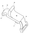
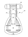
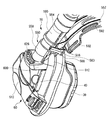
図A1は本発明のマスクアセンブリ10の斜視図である。マスクアセンブリ10はシェルアセンブリ20とクッション30とを備えている。本発明とともに用いることができるガセットつきクッションのタイプの一例は、2001年6月21日に出願され、本出願の譲受人に譲渡されたFraterらの米国特許出願第09/885,445号に開示されている。この出願はここで援用される。Frater出願において、顔との良好なシールは、マスクのストラップを締めすぎる必要なく、様々な圧力下で得られ得る。クッションのガセットは、クッションのフレームと接触する側を、クッションの患者と接触する側から分離し、これら2つの側の間に6つの自由度をもたらす。しかしながら、本発明はこのようなガセットつきクッションとの使用に限定されず、どのようなNPPV治療用クッションとも一緒に用いることができる。ここで述べられている図がクッションを示しておらず、クッションの一部またはクッションのガセット部分のみを示しているとしても、このような実施形態は完全なクッションとともに用いられることが意図されており、クッションの一部のみを示す図面の説明におけるクッションという用語の使用は限定することを意図するものではないということを理解されたい。
シェルアセンブリ20は、一般的には硬いシェル40を有しており、これにクッション30が取り付けられ得る。シェル40は、ベース42と、ベース42から上方に伸びている一対のフランジアセンブリ44および46とを有している。好ましい実施形態においては、フランジアセンブリ44および46は一般的には互いの鏡像であるが、そうである必要はない。フランジアセンブリ44および46のそれぞれは、上側フランジ、下側フランジ、およびこれらを貫く孔50を有している。好ましくは孔は、シェル40の主平坦面52に対して平行な軸を有している。図A2も参照。
【0019】
クイックリリースラッチ機構
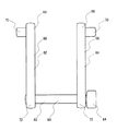
フランジアセンブリ44および46のそれぞれは、クイックリリースラッチ機構60を支持している。各ラッチ機構60は、好ましくはマスクアセンブリの製造に要する部品の数を最小限にするために同一の構成要素を用いるが、所望すれば構成要素を異ならせることもできる。各ラッチ機構60は、上側クリップリンク62と下側クリップリンク64とを有しており、これらは好ましくは同一であるが、シェル40に取り付けられる際には反転される。図A3〜A6も参照。各クリップリンク62、64はピボットピン70を有する第1の端をもつ軸方向に伸びたボディ66を有している。ピボットピン70は軸方向に伸びたボディ66から外側に伸びており、ボディ66の軸に対して垂直である軸を有している。ピボットピン70は、フランジアセンブリ44、46における各孔50に回動可能に噛み合うようなサイズで適応されている。図A4に示すように、各クリップリンク62、64はまた、第2の端72を有している。第2の端72にはそれを貫く孔74が設けられており、孔74はピボットピン70の軸に対して平行な軸を有している。
【0020】
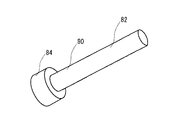
図A6において、各ラッチ機構60はまた、軸方向に伸びているシャフト82と広がった頭部84とを有するクリップピン80を有している。軸方向に伸びているシャフト82は、各アセンブリの上側クリップリンク62および下側クリップリンク64のそれぞれの孔74に回動可能に噛み合うようなサイズで適応されている。広がった頭部84は、ラッチ機構に対してピンを取り付けたり、取り外したりするためのより簡単に把持することができる面を提供し、また、ピンが孔74を通って遠くに行きすぎないようにするための位置合わせ面も提供する。
【0021】
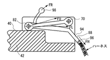
図A7に示すように、各ラッチ機構60はまた、クリップ88を有している。各クリップ88は第1の端90を有している。第1の端90にはそれを貫いて孔92が設けられており、孔92は、上側クリップリンク62と下側クリップリンク64との間でクリップピン80の軸方向に伸びるシャフト82の上方に回動可能に搭載されるようなサイズで適応されている。各クリップ88はまた、マスクハーネス係合部96を有する第2の端94を備えている。好ましくはハーネス係合部96は、一般的にはハーネス係合部96に対するユーザの頭部から伸びるハーネス部の角度と整合して、マスク10の顔側に対して角度をなしてクリップ88の中央部から遠ざかるように伸びている。図A8aを参照。したがってハーネスは、ハーネス係合部96の角度で一般的には並べられているクリップ88のハーネス係合部96へ引っ張る力FHを及ぼすことになる。ある実施形態においては、ハーネス係合部96はスロットであってもよい。ハーネスの一部はスロットを通ってクリップ88に固定され得る。一実施形態において、ハーネスは、ハーネス係合部96を通ることができるエンゲージストラップを有してもよく、Velcro(登録商標)、スナップ連結、バックルまたは他の公知の連結の使用によって、自分自身にくっつけられてもよい。各クリップ88は、クリップ88のボディから遠ざかるように伸びるフリップアーム98を有しており、これはマスク10に対してクリップ88を扱うためにマスクのユーザによって簡単に把持可能である。各クリップ88は、シェル40へ向いた方向におけるクリップ88の動きに対してポジティブストップを提供すべく、シェル40またはシェルアセンブリ20のほかの固定位置に噛みあうように適応され得る停止面95をオプションとして備えていてもよい。
【0022】
各ラッチ機構60は、以下のようにシェル40に取り付けられてもよい。最初に、それぞれのピボットピン70をフランジアセンブリ44、46の上側および下側フランジを貫く孔50の対応する部分に噛み合わせることによって、上側フランジおよび下側フランジのそれぞれに、上側クリップリンク62および下側クリップリンク64を回動可能に装着する。そして上側クリップリンク62および下側クリップリンク64の間にクリップ88を挿入する。クリップ88の幅は、一旦クリップ88が上側クリップリンク62および下側クリップリンク64の間に挿入されると、クリップリンク62、64がそれぞれのフランジ44、46からはずれるのをクリップ88が防ぐように設定される。そしてクリップ88の孔92が上側および下側クリップリンクのそれぞれの孔74に揃えられて、クリップピン80が、クリップリンク62、64およびフランジアセンブリ44、46に対してクリップ88を回動可能に装着するように孔のそれぞれに挿入される。
【0023】
以下、ラッチ機構60の動作を説明する。ラッチ機構60はオーバーセンター方式で動作する。すなわち、ハーネスからの引っ張り力FHがクリップ88のハーネス係合部96にかかると、クリップ88はラッチ機構の力のつりあいまたは力の中心の位置から離れる方向に動く傾向を有することになる。図A8(a)〜(c)に示される実施形態において、力のつりあいまたは力の中心は、シャフト82およびピン70の軸と交差する直線上にある。クリップ88に作用する力の総和が、FLのように、ピン70の軸の下方で角度をなして伸びる軸82に作用する加算された力の要素になるとすると、図A8aに見られるように、クリップ88はシェル40に対して閉止された、またはラッチされた位置に保持されることになる。しかしながら、クリップ88に作用する力の総和が、図A8aに示すFUのように、ピン70の軸の上方で角度をなして伸びるシャフト82に作用する加算された力の要素となるとすると、クリップ88は、図A8bに示すように、開放された、あるいはラッチされていない位置に向けて動くことになる。
【0024】
したがって、ハーネスの引っ張り力FHがクリップ88に作用する総和の力FLになるとすると、クリップ88はラッチされた位置にとどまる。力FRおよびFHの総和が総和の力FUになるように開放力FRがユーザまたは別の人間によってクリップに与えられると、クリップ88はラッチされていない位置に動く。当然のことながら、クリップ88に作用する総和の力がFLからFUに代わるように力FHの角度を変えると、クリップ88もラッチされた位置からラッチされない位置へと動く。この理由から、マスクに対するハーネスの位置決めを、通常の装着状況下での力FHがラッチ機構60を無意図的に外すことになる総和の力にならないように設計することが重要である。むしろ、好ましい実施形態においては、通常の状況下で、ユーザまたは他の人間によってクリップ88に付加的な開放力が加えられるときのみ機構60が外れるように意図される。外れている位置では、各ラッチ機構60は、ピン70の軸とシャフト82との間の距離の約2倍ハーネスで緩んでいる。
【0025】
図A8cに示す他の実施形態においては、シェル40は、エクステンション41を有している。ハーネスのストラップがクリップ88をまっすぐ下の方に引っ張ることを防ぎ、それによってラッチ機構60を外すのに必要な力を無意図的に提供してしまうことを防ぐために、ハーネスのストラップはエクステンション41の上方を通らなければならない。エクステンションは、ストラップが望まない方向に引っ張る力FHをクリップに対して及ぼすことを防ぐ。
上述したクイックリリースラッチ機構60の使用によって、シェル40とハーネスとの間に低プロファイル取り付け機構があてがわれ、またこの取り付けを素早く、正確に、繰り返し簡単に解除されたり、ラッチされたりすることが可能になる。ラッチ機構60は、プリセットされたストラップの調節がラッチとラッチの解除との繰り返しを通して維持されることを確実にする。つまり、ストラップが一旦ユーザに適切に調節されると、公知のマスクシステムとは異なり、ユーザはラッチ機構60によってマスクアセンブリ10を取り外したり、再装着したり、同じプリセットされたストラップの調節を維持したりすることが可能になる。さらに、各ラッチ機構60が外されたときにハーネスで起こる緩みもまた、ユーザがマスクアセンブリ10をその頭部に置いたり、頭部から取り外したりすることを容易にする。このようなクイックリリースは、ユーザにとって便利であるだけではなく、ユーザがマスクを装着している間に不快感や窒息感を感じればマスクを素早くかつ容易に取り外すことができるというあるレベルの快適さをユーザに対して提供する。もし望むのであれば、ラッチ機構の設計は、ラッチ機構60をラッチされていない位置に配置し、孔50からピン70を外すことによってラッチ機構60、およびストラップがシェルから素早く取り外されることを許容にするように構成されてもよい。
【0026】
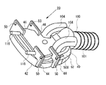
シェル
シェル40は多くの他の特徴を有している。例えば、シェル40は、シェル40の中央上部に接続されたインレットチューブ100を有していてもよい。インレットチューブ100は、加圧された供給源からマスクアセンブリ10の内部に呼吸可能な気体を供給するようにシェル40の中央上部にマスクアセンブリ10の内部に向けて開いているポート102を有している。図A1、A2およびA9を参照。エアインレットチューブ100は、エア供給路のさらなる構成要素とエアインレットチューブ100を接続するための外部のねじ山部101を有していてもよい。シェル40はまた、マスクアセンブリ10から気体を排出するための、エアインレットチューブ100のそれぞれのサイドに設けられた一対の呼気ダクト104を有していてもよい。各呼気ダクト104はシェル40のそれぞれのサイドを向きの位置にマスクアセンブリ10の内部に向いて開いているポート106を有している。図A9aから最もわかるように、エアインレットチューブ開口ポート102は、シェル40の内表面110から伸びている一対の持ち上がった壁108によって呼気ダクト開口ポート106から隔てられている。壁108は、エアインレットチューブ開口ポート102に隣接する位置からシェル40に沿って下方に伸びており、下方にいくにつれて、ユーザの鼻に対するクリアランスを与えるように外側に角度をなしている。壁108はシェル40の底部の端115に達する前になくなる。壁108はマスクにおける中央気体吸入チャネル112を規定し、これを通して加圧された気体がユーザの鼻孔に流れることが可能である。壁108はまた、マスク内部の中央気体吸入チャネルの外側に一対の側部気体排出チャネル114を規定し、これを通して呼気が呼気ダクト104に流れることが可能である。
【0027】
壁108は、マスク内で吸入する気体を排出気体と分離することによってマスク内の空気の流れを改善して、酸素リッチな吸入気体と呼気ダクトを通したマスク外部との短絡を減少する助けとなる。呼気ダクト開口ポート106の間に壁108を配置した状態での中央エアインレットチューブ開口ポート102の外側に対する呼気ダクト開口ポート106の位置決めは、マスク内の気体の自然な流れを利用する。つまり、ユーザが息を吸い込むとき、気体は中央チャネルを通ってユーザの鼻孔へ流れることができる。しかしながら、ユーザが息を吐くとき、呼気は鼻孔から下方に流れ、シェルの下端にぶつかり、シェルの下端に沿って外側に一対の側部気体排出チャネルへと移動する。したがって、壁108によって与えられる流れの制御は、吸入する空気と呼気ダクト104との短絡を減少させるだけではなく、マスク内の二酸化炭素レベルを下げ、呼気の吸入時の負担への余波を最小限にしつつユーザの鼻孔から呼気ダクト104へと呼気が移動することを助ける。
【0028】
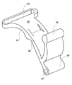
あるいは、図A9bに示すように、シェル40は、エアインレットチューブ開口ポート102の下に位置し、中央バッフル109によって隔てられたポート106を有する単一の中央部に位置する呼気ダクト104を備えていてもよい。
呼気ダクト104は情報にカーブして、エアインレットチューブ100に並んでシェル40に対して情報に向いている排出ポート120を有していてもよい。こにようにして、呼気ダクト104はマスクの内部から呼気を受け取り、この気体を、エアインレットチューブ100の横で上方に排出ポート120から外に導く。このような方法でマスクの外部へ呼気を導くことは、エアインレットチューブを上方に進む排出流を与える。これにより、従来のマスクではマスク正面からの排出気体が生じることがあり、ユーザがベッドパートナーの方を向いているときにベッドパートナーを邪魔することがあったが、マスクをしたユーザの顔またはユーザのベッドパートナーに向けての排出流が最小限になる。また、排出ポートをユーザの鼻孔から遠くにしたことで、マスクから漏れる呼吸時の雑音を減少させることができる。
呼気ダクト104をシェルのベースから離れるように上方にカーブさせることにより、音をさらに低減し、マスク内に呼気ディフューザを収容するように排出ポートの断面を構成することがより容易になる。
【0029】
シェル40はまた、マスク10の底部に位置する一対のアクセスポート118を有してもよい。アクセスポート118は、薬または酸素をマスク内部に供給することができる1以上の供給チューブに接続可能である。アクセスポート118はまた、マスク内部圧力、CO2レベル等を制御、測定する目的でのマスク10の内部へのアクセスに使用されてもよい。図では2つのポートが示されているが、アクセスポートの数は好きなように変えることができる。使わないときには、マスク内部からの漏れを防ぐためにアクセスポート118にキャップをかぶせておくことができる。アクセスポート118は、供給チューブをエアインレットチューブ100に並んで沿わせ、チューブのもつれを最小限にするようにシェルの上部に位置してもよく、あるいは所望に応じてマスクアセンブリ10のどこに配置してもよい。
【0030】
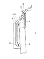
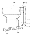
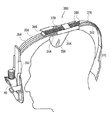
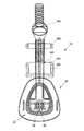
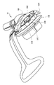
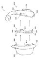
全体のアセンブリ
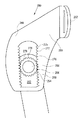
図A10は、全体のマスクアセンブリ10の部分的に欠けている側面図である。シェルアセンブリ20および(一部のみを図示している)クッション30に加えて、マスクアセンブリ10は、ヘッドマウント130およびヘッドマウント高アジャスタ140を有している。ヘッドマウント130およびアジャスタ146は、エア供給チューブ100とマスクアセンブリ10との間の接続を提供する。図A11に示すように、ヘッドマウント130はユーザの額に接するベース部132を有している。ベース部132はユーザの額の形状に大まかに合うようにカーブしている。フォームラバーまたは他の柔らかい層をベース部132の下側の表面に設けて、マスクアセンブリ10の装着時のユーザの着け心地のよさを高めてもよい。ベース部132はまた、ヘッドマウント130をユーザの頭部に固定するためのハーネスにヘッドマウント130を接続する3つのスロット134および136を有している。2つの側部に位置するスロット134はユーザの頭部の側方から伸びているハーネスに載り、中央に位置するスロット136はユーザの頭部の上部から伸びているハーネスの一部分に載る。ハーネスにヘッドマウント130を接続するために、スナップ接続、フックによる接続、Velcro(登録商標)による接続や他の接続など、他のタイプのコネクタを用いてもよい。
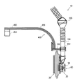
【0031】
ヘッドマウント130はさらに、ベース部132に載せられた台座138を有している。台座138はエアコネクタチューブ142に流れるように接続されるボール・ソケットジョイント200を支える。ボール・ソケットジョイントは後で詳細に説明する。エアコネクタチューブ142は、高さアジャスタ146に接続されるねじ山部144を有している。ヘッドマウント高アジャスタ146は、ヘッドマウント130からの空気の流れがエアインレットチューブ100に流れるのを許すようにうつろなチューブとして一般的に構成されている。ヘッドマウントアジャスタ146は、エアインレットチューブ100のねじ山部101に接続する第1のねじ山部148と、エアコネクタチューブ142のねじ山部144に接続する第2のねじ山部150とを有している。高さアジャスタ146はまた、アジャスタ146を回転させてヘッドマウント130とシェルアセンブリ20との間の空間を調節する中央に搭載されたフィンガーホイール152を有している。
【0032】
好ましい実施形態において、ヘッドマウント130とシェルアセンブリ20との間の距離をアジャスタ146のみを回転させることによって、ヘッドマウント130またはシェルアセンブリのどちらかを回転させることなく変えることができるように、ねじ山部148および150は、エアインレットチューブ100およびエアコネクタ142のそれぞれに対応するねじ山部と同様に、一方は右回りに、もう一方は左回りにねじを切られている。図A10参照。この特徴により、マスクアセンブリ10が一旦ユーザの頭部に置かれると、全てのねじ山部が右回りまたは左回りに切られていたら必要であったであろうようにヘッドマウント130かシェルアセンブリ20かを回転させてマスクアセンブリを外したりする必要もなく、最もよいはめ込みおよび着け心地のために、ユーザがヘッドマウント130とシェルアセンブリ20との間の空間を調節することが容易になる。
好ましくはないが、ねじ山部を全て右回りまたは左回りに形成してもよい。さらに、それぞれの合わせられる構成要素の内側および外側のねじ山部は反転させてもよい。エアインレットチューブ100、高さアジャスタ146およびエアコネクタチューブ142の間のねじ山による接続は、接合部における実質的な空気のいかなるリークをも防ぐように十分に精密な許容誤差を有することが好ましい。さらに、アジャスタは、通常の装着状況下で設定されたままにされ、許容誤差は、ユーザが調節を変更したいときに指のみでアジャスタ142を容易に回転させるを妨げるほどにはきつくない。
本発明の好ましい実施形態において、シェル40はポリカーボネイトから形成されており、ラッチ機構60はアセタールまたはナイロンのような半硬質プラスチック材料から形成されてもよい。またヘッドマウント130はアセタールまたはポリプロピレンから形成されてもよい。様々な構成要素は、他の公知の材料から形成することができる。
【0033】
ボールおよびソケット
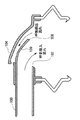
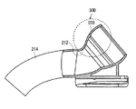
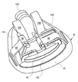
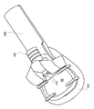
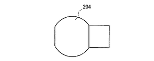
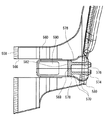
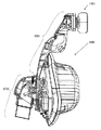
加圧された空気の供給源とマスクとの間の空気の接続のための既存のスイベルおよびエルボ構成は、エルボ周辺の漏れ、およびきしみのような不都合を有し得る。本発明の他の実施形態では、200個のこれらの欠点が、マスク10へ呼吸可能な空気を取り入れる接続のための新規のボール・ソケットジョイント200を有するマスクアセンブリ10によって解消されうる。ボール・ソケットジョイント200はまた、エア供給チューブとマスクとの間にさらなるフレキシビリティを与えることによってガセット部を組み込む本発明の一実施形態の利点を増し得る。ボール・ソケットジョイント200は図A12〜A16に詳細に示されている。図A12〜A16に示されている実施形態において、ボール・ソケットジョイント200はベースプレート202の近くに搭載されており、カーブしたエアコネクタチューブ214を有している。ジョイント200の詳細は図A10およびA11の実施形態に適用可能である。図A12は、患者の額にハーネス・ヘッドギアで取り付けることができるベースプレート202に取り付けられたボール・ソケットジョイント200を示している。または、ボール・ソケットジョイント200はマスクシェル40に直接搭載されてもよく、あるいはシェル40のエアインレットチューブ100に接続されたエア供給チューブにのみ取り付けられることも可能である。この後者の実施形態において、例として図F38〜F39に示しているが、ボール・ソケットジョイント200は、シェル40または他の静止している構造に堅く取り付けられてはいないために自由に動くことができる。ジョイント200は、フレキシブルエアチューブ206の末端に搭載されたボール204を有する。エアチューブ206は加圧された空気の供給源との接続のために適合されてもよい。ボール204はソケット208に搭載されるように適合される。エアチューブ206からの加圧された空気は、ボール204の開口210を通ってソケット208に流れ、ソケット208の開口212を通ってチューブ214を介してマスク10に流れる。ソケット208は、内周シート216と、ソケット208の外側の縁にリップ218を有している。ボール204は、必要に応じて、比較的簡単にソケット208に入れたり出したりすることができる。一旦ボール204をソケット208に入れると、ボール204は、ソケットのシート216およびリップ218の間に小さなクリアランスをもって落ち着く。
【0034】
従来のボール・ソケットジョイントは一般的には、空気の漏れを防ぐが、ボールの運動時に大きな摩擦を生じ得る非常に小さな許容誤差しか有しておらず、したがって所望され得るいかなる可動度およびフレキシビリティをなしにしてしまっている。しかしながら、ボール204とソケット208のシート216およびリップ218との間に提供される小さな隙間によって、ボール204がソケット208に対して自由に動いたり回転したりすることが可能になる。ボール204が動いている間、隙間によって、少量の加圧された空気がボール204とソケット208との間を大気中に逃げることができる。しかしながら、ボール204が静止位置にあると、空気の圧力がボール204をリップ218に対して押しつけ、ボール204が再び動くまでボール204とソケット208との間の接合を封止する。図A16を参照。ボール・ソケットジョイント200によって、エア供給チューブは、ソケット208の周りで、ソケットから伸びている円錐状の移動範囲のどこにでも移動可能であり、従来のエルボスイベルジョイントと比べて、エアチューブの向上した動きを提供する。
【0035】
テスト時には、本発明のボール・ソケットジョイントは、2〜20cm水の圧力下で1ltr/minを下回るレートでリークすることがわかった。ボール・ソケットジョイント200は、例えばポリプロピレンのような当該分野でよく知られている方法および材料で形成してもよい。この材料は、柔らかなワックス状の表面の風合いを有するという利点があり、これが動いている間の部品間の雑音を低減する助けとなる。ボールは、好ましくはポリカーボネイトから形成される。ボール・ソケットジョイント200は、本発明の残りの部分と同様、このようなジョイントまたはマスク部品の製造に用いられることが知られているいかなる材料から作製されてもよい。しかし、最良の動作のためには、ボールおよびソケットの一方は比較的硬い材料から形成され、他方は比較的フレキシブルな材料から形成されることが好ましい。
【0036】
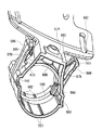
シェル40の他の実施形態を図A17およびA18に示す。この実施形態では、シェル20の内壁160は、クッション30の方に突出するように高くされている。この実施形態は特に、上述し、図A1およびA10に示したように、ガセットつきクッションとともに使用されるために設計されている。内壁160は、クッション30のガセット部32の加圧および動きに干渉することがないようにガセット部32の内部に実際には接触することなくクッションのガセット部32の方に突出するように構成されている。このガセット部32への突出は、ガセットがしぼんでいる、あるいは閉じている状態にあるときにシェル40に対するクッション30の位置合わせを維持する助けとなる。突出は、効果的な位置合わせを提供するために、周辺部あたりにまで続いている必要はなく、同様の効果を得るために独立した別個の突出部を有していてもよい。
【0037】
図A17およびA18の実施形態はまた、シェル40の周辺部に伸びるフランジ162を有している。フランジ162は、マスクが使用されるときにクッション30のガセット部32の正面側に接触し、クッションから顔に対してもっと力をあたえるためにクッション30のガセット部32を実質的にかたくする。この特徴は、さらに、上述した2001年6月21日に出願されたFraterらの米国特許出願第09/885,445号に記載されている。本実施形態のシェル40はまた、サイズを増した呼気ダクト104を備えている。エアインレットチューブ100は、本実施形態においては、図A2の実施形態と比べて短くされている。
【0038】
他の実施形態
さらに、クリップ88の他の実施形態を図A18およびA19に示す。この実施形態において、フリップアーム98は、図A7に示されている実施形態における中間孔92および端部94の代わりに、孔92のほぼ真上に位置している。フリップアーム98のこのような配置によって、ラッチ機構60が閉止状態にあるときに、フリップアーム98は互いに近接している。これにより、両フリップアーム98は、閉止位置にあるときにはユーザの親指と人差し指との間で同時に握られることが可能になり、ラッチ機構60がラッチされておらず、かつ開放されているような位置に動くことが可能になる。各フリップアーム98は、フリップアーム98がベッドリネンともつれたり、ユーザまたはベッドリネンが動いたときにラッチ機構を意図的ではなく外してしまうような機会を減らすために、より低い高さを有している。本実施形態では、フリップアームは両側に握りエクステンション99を備えている。握りエクステンション99は、好ましくは、ユーザの親指と人差し指との間でフリップアーム98をしっかりと握ることができるように皿の形にされている。この実施形態のクリップ88は、図A18に示すシェル40の上表面によりよく適合するための停止面98を有していない。
【0039】
シェル40の他の実施形態を図A20〜A21に示す。本実施形態では、呼気ダクトは、排出ポート120の断面積を増加させるようにさらにサイズを大きくされており、呼気速度を減少させたり、呼気ディフューザ用のさらなる空間を提供したりする。
【0040】
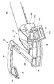
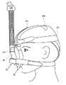
他のマスクアセンブリ
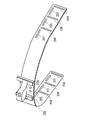
図F1〜F9はマスクアセンブリ10の他の実施形態を示している。この実施形態では、マスクアセンブリは、上述した実施形態のような別個のヘッドマウントを使用しない。代わりに、シェル40は、シェル40の上部から伸びている延長ブラケット220を備えている。延長ブラケット220は、概して長方形状であるが、他の形状を有していてもよい。延長ブラケット220は、ヘッドストラップ224の保持チャネル222を噛み合わせるように構成されている。延長ブラケット220の辺および保持チャネル222は概して平行であるので、ヘッドストラップ224とシェル40/クッション30の本体との間の距離を調整するために、ヘッドストラップ224は延長ブラケット220を上下させるように移動可能である。延長ブラケット220に沿ってヘッドストラップ224に行われる異なる調整を示している図F2およびF3を比較。
【0041】
図F4およびF5において、ヘッドストラップ224はまた、保持チャネル222に設けられた、延長ブラケット220の下面に沿って位置する複数のつめスロット234のいずれか1つに噛み合うように適合された一対の突起232を有している。ヘッドストラップ224が延長ブラケット220に沿って突起232がスロット234の一つに噛み合うまで調整されるとき、ヘッドストラップ224は、通常の装着状況下では、ユーザが延長ブラケット220に対してヘッドストラップ224を再調整するまではこの調整された位置で保持される。突起232の高さは、このような調節を行うために必要以上の力を要せずに突起232を一つのつめスロット234から他のスロットへ移動させることができるように、ヘッドストラップ224のフレキシビリティと連携して設定されている。好ましい実施形態においては、突起232およびつめスロット234の一方または両方の端は、つめスロット234から突起232がはずれる動きを容易にするために丸められていてもよい。図F4では2つの略円形の突起232が示されているが、他の数および形状の突起を用いることもできる。ヘッドストラップ224はまた、保持チャネル222の上方に設けられた保持ループ226を有している。図F3において、保持ループ226は、ボール・ソケットジョイント200でエアインレットチューブ100に接続するコネクタチューブ228にかみ合い、保持するようなサイズに形成されている。本実施形態において、ボール・ソケットジョイント200のシェル40に対する位置決めは、上で示した実施形態と比べて反転されていてもよい。所望すれば、位置決めは上述した通りとすることもできる。したがって保持ループ226は、接続チューブ228およびボール・ソケットジョイント200の両方を支持する。
【0042】
図F4において、ヘッドストラップ224は、複数の調節スロット230および調節スロット231を両方の自由端に有している。調節スロット230は、ヘッドストラップ224の自由端の間を伸びているハーネスまたは保持ストラップの側部に接続するためのものであり、調節スロット231は、ヘッドストラップ224をユーザの頭部に固定ためにヘッドストラップ224の自由端の間を伸びているハーネスまたは保持ストラップの上部に接続するためのものである。ヘッドストラップ224がその外表面上に保持チャネル222を有しているときには、ヘッドストラップ224の内表面は概して滑らかに保たれてもよい。
本実施形態において、ヘッドストラップ224は実際にはユーザの額には接触せず、ユーザの額の正面で浮かんでいる。クッションのガセット部が膨らませられると、シェル40はユーザの顔から押し出され、ヘッドストラップ224の自由端の間を伸びているハーネスによって定位置に保持されているヘッドストラップ224にテンションをかける。このテンションが、ヘッドストラップ224をユーザの額から離す方に引っ張る。その結果、ユーザの顔との接触がより少ないためにユーザは向上した快適さを得ることができ、また、公知のマスクアセンブリでは生じる、マスクアセンブリ10との接触によってユーザの額に見苦しい圧力の痕が残るのを防ぐことができる。
【0043】
図F5において、アクセスポート118は、前記実施形態よりも互いにより近づき、シェル40上のより中央に配置される。図F6において、アクセスポート118は、シェル40の底部に対向するように、シェル40の正面から伸びている。図A17に示した実施形態のように、シェル40は、クッション30のガセット部に接触して支持し、ガセット部の働きを硬くする、周辺部あたりに伸びるフランジ162を有している。
図F8において、本実施形態における各ラッチ機構60は、図A1〜A7に示されている実施形態の2つのクリップリンク62、64およびピン80を単一のクリップリンク240で置き換えている。各ラッチ機構60はまた、下記に述べる点以外は図A1〜A7に示すクリップと類似しているクリップ88を有している。図F7参照。
【0044】
単一のクリップリンク240は、図F8に示されているが、各フランジアセンブリの孔50に噛み合う2つのピン70を有している。2つのピン70はピンアーム70上に取り付けられており、ピンアーム71は、孔50にピン70を入れる隙間を生じさせて互いの方に締め付けることができるようにバネの作用を提供すべくリンク240の中央部から遠ざかる方に自由に伸びている。同様に、単一のクリップリンク240は、クリップ88の孔92に噛み合うための2つの内側で向かい合っているピン83を有している。ピン83はピンアーム85に取り付けられており、ピンアーム85は、孔92にピンを入れる隙間を提供するように外側に撓むことができるようにバネの作用を提供すべく、リンク240の中央部から離れる方向に伸びている。単一のクリップリンク240はまた、一対の中央に位置するサイドエクステンション242を有している。これらのサイドエクステンション242は、ラッチ機構60がラッチされたときに、フランジアセンブリの内表面にかみ合い、ラッチ機構60に側方安定性を提供する。
単一のクリップリンク240はまた、ピンアーム85の間をピン83に向かって伸びている第3のエクステンション244と、ピンアーム271の間を伸びている第4のエクステンション216とを有している。第3のエクステンション244は、クリップ88上のスロット89に噛み合うように適合された延長タブ245を有している。スロット89は、ラッチ機構60が開放位置に置いて最も伸びたときにスロット89の端部表面がタブ245に接触して、ラッチ機構60のさらなる動きを積極的に停止させるように構成されている。スロット89はまた、ラッチ機構60が閉止位置にあるときにタブ245を積極的にストップさせるように構成されている。エクステンション242、244および246は全て、隣接するピンアーム71および85の余計な動きを制限するように動作し、ラッチ機構60が閉止位置にあるときにクリップ88に対して下からの支持を提供する。クリップ88は、オプションとして、エクステンション246に接触し、ラッチ機構60が閉止状態にあるときにさらなるストップ機構を提供するように下面上に突起91を備えることもできる。
【0045】
図F9は、図F1〜F3に示すボール・ソケットジョイント200の実施形態のボール204およびソケット208を示している。
【0046】
他のマスクアセンブリ
図F38〜F40およびF45〜F46は、本発明のマスクアセンブリ10の他の実施形態を示す。本実施形態においては、シェル40は延長されたエアインレットチューブ100を有している。ヘッドストラップ450は、ハーネスに接続するための正面ハーネスマウント452と、ハーネスに接続するための上部ハーネスマウント456と、ユーザの頭部の上部に接触し、ヘッドストラップ450を安定させるための上部ヘッドマウント454とが接続される接続部材460を有している。ハーネスマウント452および456のそれぞれは、ハーネス461に接続するためのスロット458を有している(図F45およびF46を参照)。しかし、他の取り付け機構を用いてもよい。図F1〜F9に示されている実施形態と同様に、正面ハーネスマウント452、上部ハーネスマウント456またはシェル40のいずれもユーザの頭部には接触しない。代わりに、クッションのガセット部が膨らまされると、シェル40はユーザの顔から離れる方に押され、正面ハーネスマウント452およびハーネス461にテンションをかけ、したがって正面ハーネスマウント452および上部ハーネスマウント456をユーザの頭部から離れる方向に引っ張る。図F45〜F46に示されている実施形態においては、ハーネス461が正面ハーネスマウント452に接続するのみとして示されている。しかしながら、他の実施形態では、ハーネス461を、ハーネスマウント452および456の両方に接続するように構成することができる。
【0047】
正面ハーネスマウント452は、延長されたエアインレットチューブ100にスライド可能に接続されるように適合された分割保持ループ462を有している。このようにして、シェルアセンブリ20およびクッション30は、ヘッドストラップ450に接続されており、特定のユーザにマスクアセンブリ10をフィットさせるためにヘッドストラップ450に対して縦方向に調節可能である。図F1〜F8を参照。しかしながら、図F38の実施形態では、各クリップ88の各フリップアーム98は、ラッチ機構60が閉止位置にあるとき、フリップアーム98が互いに近接して位置し、各フリップアーム98の上側および下側の縁をユーザの親指と人差し指との間に容易に握ることを可能にするるために十分にもちあげられているように構成されている。したがって、フリップアーム98の両方をユーザの親指と人差し指との間に握って、各ラッチ機構60を外し、各ラッチ機構60が片手のみを使って開放位置に動くことができるように同時に片手で操作することができる。
他の実施形態において、ここで述べたラッチ機構60のいずれも、ラッチ位置でラッチ機構を保持するポジティブラッチを有するように改変してもよい。このような実施形態の一つにおいては、ポジティブラッチは、ラッチ機構とシェルの間に設けられた、ユーザによって外されるまでラッチ機構をラッチ位置に積極的に保持するつめ機構であってもよい。このようなポジティブラッチ機構は、ラッチ機構が完全にラッチされた位置にあることを知らせる、クリックのような音を立てるインジケータ、または他の感覚によるインジケータを提供するように構成してもよい。
【0048】
ヘッドストラップ450およびエアインレットチューブ100は、ヘッドストラップ450およびエアインレットチューブ100の間の調節された位置を維持するために、図F1〜F8に示した実施形態に関して上述したつめ機構に類似したつめ機構を備えていてもよい。あるいは、エアインレットチューブ100および保持ループ462は、調節された位置を維持することができる2つの構成要素の間の調節可能な接続を提供するようにねじ山をつけられていてもよい。
【0049】
他のラッチ機構
図F41〜F43はラッチ機構60およびシェルアセンブリ20の他の実施形態を示している。この実施形態では、1個のラッチ機構60のみが用いられる。上述したように、クリップ88はクリップリンク240に回動可能に取り付けられており、これはシェル40に回動可能に取り付けられている。クリップ88はマスクハーネスエンゲージ部96を有する第2の端部94を有している。上述した2つのラッチ機構の実施形態と同様の量のハーネスのたるみの巻き上げを提供するために、本実施形態の単一のラッチ機構60は上述した各ラッチ機構の約2倍の長さである。したがって、本実施形態のクリップ88およびクリップリンク240は、図F1〜F9に示した実施形態の各クリップ88およびクリップリンク240の約2倍の長さである。クリップ88は、オプションとして、前記実施形態と同様に、クリップ88を操作するためのフリップアーム98を有することも可能である。しかしながら、クリップ88およびクリップリンク240の長さの増加のために、クリップ88の第1の端部90は、概して、閉止状態にあるときにシェル40の他の側部に伸びているので、ラッチ機構60は、クリップ88の露わになっている第1の端部90を操作することによって外すことができる。
【0050】
図F42では建った一つのラッチ機構60が用いられているので、ハーネス噛み合わせクリップ470は本実施形態ではハーネスの第2の側部にはまるように設けられている。図F43に示すように、ハーネス噛み合わせクリップ470は、上述した実施形態の左側のラッチ機構と同様に、シェル40の孔50に回動可能に噛み合うように一対の内側に伸びているピン472と、ハーネスと噛み合うためのマスクハーネスエンゲージ部474とを有している。ピン472はフランジアセンブリ44の外側から孔50に噛み合うので、クリップリンク240の幅が好ましくはラッチ機構60に安定性を与えるように閉止状態のフランジアセンブリ44の内側の側部に噛み合うように設定されていたとしても、ハーネス噛み合わせクリップ470は、閉止状態にあるときのラッチ機構60とは干渉しない。あるいは、固定されたハーネス噛み合わせ部をシェル自体の上に設けることもできるが、本実施形態では、同じシェル40を二重または単一のラッチ機構モードで用いることができる。また、示されている実施形態では、ハーネス噛み合わせクリップ470と同様に、同一の構成要素を用いて、左回りおよび右回りのマスクバージョンを提供すべく、ラッチ機構60をシェル40の片側でシェル40に取り付けることができる。
【0051】
本実施形態の改変において、長さを増加させた2つのラッチ機構60をシェル40上に設けることができる。一方のラッチ機構60は、より外側に配置されたラッチ機構が内側のラッチ機構にかぶせるように、延長されたフランジアセンブリによってシェル40から他のラッチ機構よりも遠くに位置する。ラッチモードでは、内側のラッチ機構がまず閉止位置に操作され、それから外側のラッチ機構である。ラッチされていないモードでは、プロセスが逆になる。このような実施形態は、ハーネスのたるみ巻き上げ能力を上述した実施形態と比べて約2倍にする。あるいは、内側のラッチ機構は、ユーザによる握り部材の操作が内側のラッチ機構を開け、そして、同時に外側のラッチ機構を開けるように、外側のラッチ機構の動きに干渉しない握り部材を備えることもできる。
ここで述べたラッチ機構のそれぞれは、図A8aおよびA8bに関して説明したものと同じオーバーセンターの原理で動作する。
【0052】
他のヘッドマウント調節機構
図F10〜F11は、ヘッドマウント調節機構250の他の実施形態を示している。この機構は、エアインレットチューブ100の対向する側部上でシェル40(一部分のみを示している)から伸びている、略平行に伸びる一対のスプリングタブ252を有している。概して丸いロッキングギア254は各スプリングタブ252の遠位端に固定して取り付けられており、好ましい実施形態では、スプリングタブ252に一体的に成型されている。複数の歯256が各ロッキングギア254の周上に等間隔に配置されている。言及している実施形態では、ロッキングギア254は互いに同軸を有しており、各ロッキングギア254は、ユーザによるロッキングギア/スプリングタブアセンブリの操作のために盛り上がった突起258を有している。
【0053】
ヘッドマウント260はユーザの額をはめ込むベース262と、ヘッドストラップまたはハーネスにヘッドマウント260を取り付けるためのスロットまたは他の取り付け機構を有している。ヘッドマウント260は、一対の略平行に伸びるブラケット266を有している。各ブラケット266は、それを貫く細長いスロット268を有しており、細長いスロット268の長手方向の軸は互いに略平行である。細長いスロット268のそれぞれは、略直線状であり、平行であり、対向するロッキング歯270の一対の列を有している。ロッキング歯270およびロッキングギアの歯256は、容易にかつしっかりと互いに噛み合うことができるように、それぞれが形成されている。同様に、ロッキング歯270のピッチは、ロッキングギア歯256のピッチに対応するように設定されており、歯の列270の間の距離は、歯270とギア254との間の適切なかみ合わせを提供すべくロッキングギア254の直径に対応するように設定されている。図F10〜F11に示されている実施形態では、ロッキング歯270は、略円形の頭部275と、よりとがった根元277とを有しており、それに対応して歯256はよりとがった頭部276と、略円形の根元278とを有している。他のギア形状および構成も用いることができる。
対向する歯の列270は略平行であり、略円形のロッキングギア254と容易に噛み合うような距離離れているので、ロッキングギア254は、スロット268の実質的に全長に渡って複数の別々の点で歯の列270と噛み合わせることができ、それによってヘッドマウント260とシェル40の本体との間の距離を変えることができる。またこの構成によって、ロッキングギア254の周りの異なる歯256に歯270を噛み合わせることによって、シェル40に対するヘッドマウント260の角度を(歯のピッチによって課される限界内で)変えることが可能になる。この角度は、ある点で、ヘッドマウント260のある部位がシェル40またはクッション30のある部位に接触して止められるので、ロッキングギア254の周りには完全には達しない。しかしながら、大半のユーザにとっての大半の例においては、シェル40に対するヘッドマウント260の所望の角度は実質的に90°よりも小さい限られた範囲内にあるので、ほとんど心配はない。
【0054】
したがって、どの歯270が歯256に噛み合うかを選択することによって、ヘッドマウント260とシェル40との間の距離および角度の両方を、ユーザに所望のはまり具合を提供するように同時に変えるか、互いに独立して変えることができる。このために、スプリングタブ252はかなり硬いが、スロット268の上方を伸びている対向する突起258をユーザが締め付けるときに、スプリングタブが互いに向かって動き、それによりロッキングギア254がロッキング歯270からはずれるように、十分にフレキシブルである。図F12を参照。ヘッドマウント260とシェル40との間の所望の距離および角度は望み通りにセットされ、スプリングタブ252は、ロッキングギア254をロッキング歯270に噛み合わせることができ、所望の位置でヘッドマウント260をロックするようにリリースされることができる。スプリングタブ252のフレキシビリティの程度は、その厚さ、材料および/あるいは形状を変えることで変更することができる。
歯256と歯270との間のかみ合わせを容易にするために、歯256の外側の先端は丸められることができる。歯256および270の厚さ、ならびに、それゆえにそれぞれの歯の間の噛み合わせの量は、使用時に調節機構が行使することが予想される力の大きさに基づいて設定される。予想される力が大きいほど、歯は厚くなり、歯の間の噛み合わせは大きくなる。ヘッドマウント260の強度および安定性を増すために、1以上の支持部材272が延長ブラケット266に相互接続される。また、ヘッドマウントは、エア供給チューブがエアインレットチューブ100への接続のために引き回されることが可能であるように延長ブラケット266の間に位置する通路274を有している。さらに、スロット268の端部は、276で示されているように、ロッキングギア254のための増加された隙間を提供するように半円にされており、それによってロッキングギア254と歯の列270との間の噛み合わせの長さを増加させることが可能である。あるいは、ヘッドマウント260およびシェル40上の相互作用構成は反転することもできる。
【0055】
図F13およびF14調節機構250の他の実施形態において、各ロッキングギア254は概円柱状の突起部278を備えている。突起部278は、対向する歯の列270の頭部の間の距離とほぼ同じか、わずかにそれよりも小さい外径を有しており、また好ましくは、スプリングタブ252が機構250の調節のために締め付けられたときに突起部278はそれぞれのスロット26の歯に噛み合ったままであるのに十分な距離だけ、スロット268を超えて伸びる高さを有する。このようにして、突起部278は、ロッキングギア254が歯の列270の列からはずれたとしても歯の列270に動くことができるように噛み合ったままであるので、機構250の調節中にヘッドマウント260とシェル40との間で向上した安定性が提供される。
図F13およびF14に示される本実施形態では、各スロット268の遠位端280はカーブしており、ヘッドマウント260とシェル40との間の距離が最大に調節されたときに、歯270と歯256との間の噛み合わせがロッキングギア254の約180°であるように歯270を備えている。この噛み合わせの増加は、ヘッドマウント260とシェル40との間の増加した距離が調節機構250の安定性を減少させるように働く時に、調節機構250にさらなる安定性を提供する。スロット268のカーブした歯のついた遠位端280は、機構250の最大調節距離で機構250に角度調節能力を提供し続ける。この実施形態では、さらに盛り上がった突起部258はユーザによる操作には必要とされず、突起部278はオプションとして、皿状、あるいは材料の節約のためにうつろであってもよい。本実施形態では、歯256および270は、前述した実施形態におけるよりもわずかに異なる構成を有しており、各突起部の外径はロッキングギア254の根元の径とほぼ同じである。
図F15〜F18は、シェル40の他の実施形態を有する調節機構250の斜視図である。本実施形態では、一つの呼気ダクトポート260がエアインレットチューブ102の下方に設けられており、側方に伸びるバッフル282はこれらの間をこれらのポートを通る2つの気体の流れを分離するように伸びる。本実施形態においては、ダクトポート106は、上方に伸び、エアインレットチューブ100を部分的に取り囲む単一の呼気ダクト104を接続し、呼気は単一の排出ポート120を通って出ていく。
【0056】
他のヘッドマウント調節機構
図F19〜F30は、ヘッドマウント調節機構300の他の実施形態を示している。調節機構のシェル部302は、図F10〜F18に示されているシェルの実施形態のいずれとも同じであってもよく、スプリングタブ252と、ロッキングギア254と、ロッキングギア254の周囲に位置している複数のロッキング歯256を有している。所望すれば、シェル40を変更してもよい。
図F20において、調節機構300のヘッドマウント部340は前記実施形態とは異なっている。ヘッドマウント部304は、一対の略平行に伸びるブラケット266を有するロッキングブラケット306を備えている。各ブラケット266は、それを貫く略円形のスロット268を有しており、2つのスロット268は互いに略同軸である。各スロット268は、ロックするように歯256を噛み合わせるように配置され、構成されたスロットの内周の周りに配置された複数のロッキング歯270を有している。各スロット268は円形であるため、本実施形態の歯270と歯256との間の噛み合わせは、ロッキングブラケット306とシェル40との間の角度の変化を許容するのみであり、2つの構成要素の間の高さ調節を許容しない。この角度は、スプリングタブ252を押し下げて、ロッキングブラケット306を、前記実施形態に関して上述した方法と同じようにして回転させることによって調節することができる。
【0057】
図F22では、ロッキングブラケット306は、接続ブラケット312の第1の延長タブ310をスライドして受けることができるようなサイズで構成されている保持チャネル308を有している。接続ブラケット312は、第1の延長タブ310に対して角度をなして伸びている第2の延長タブ315を有している。接続ブラケット312は、略L字状であるが、第1および第2の延長タブの間の角度は90°である必要はなく、好ましい実施形態では100°に近い。しかしながら、意図したユーザに対して最良のフィット感を与えるいかなる角度を選ぶことも可能である。図示されている実施形態では、第1の延長タブ310は、エアチューブのためのクリアランスを提供するようにその末端の限界の大半について開放されるが、このようなクリアランスはタブ310上の囲まれたスロットによって提供することもできる。タブ310の各側部は複数の間隔のあいたつめスロット314を有している。対応して、ロッキングブラケット306は、一対のつめスプリングアーム316を備えている。各つめスプリングアーム316は、対向する側から保持チャネル308に向けて突出しており、つめスロット314のそれぞれの対に噛み合って、ロッキングブラケット306に対して所望の調節された位置に接続ブラケット312をロックするように適合されている持ち上がったつめ突起部318を有している。好ましくは、ロッキングブラケットが2つのつめスプリングアーム316を用いているとき、1以上のスプリングアームをオプションとして用いることができる。さらに、持ち上がったつめ突起部318は構成要素の動き、調節および寿命を楽にするように、スプリングアームの端部に配置されることが好ましいが、持ち上がったつめはスプリングアーム上にある必要はなく、保持チャネル308の対向する内部の壁上に位置しているのみであり得る。
【0058】
この構成によって、持ち上げられた突起部318が所望の位置でつめスロット314に噛み合ってロッキングブラケット306に対して接続ブラケット312をロックするまでタブ310を保持チャネル308内でスライドさせることによって、接続ブラケット312の位置をロッキングブラケット/シェル/クッションに対して前後に調節することが可能であり、それが接続ブラケット312に取り付けられたヘッドマウント320をロッキングブラケット/シェル/クッションに対して前後に調節する。持ち上がったつめ突起部318および/またはつめスロット314は、ロッキングブラケット306に対して接続ブラケット312を動かすために必要とされる力の量を少なくするように面取りをされていてもよい。同様に、スプリングアーム316のサイズ、形状および構成は、所望の範囲内で接続ブラケット312を動かすために必要である力を調節するために、突起部318上でスプリングアーム316によって与えられるスプリング力を変化させるように変えることができる。タブ310の遠位端は、保持チャネル308への挿入を楽にするために面取りされ得る。
【0059】
接続ブラケット312の第2の延長タブ315は、中央に配置された間隔をあけたつめスロット322の列を備えており、つめスロットの列は、ヘッドマウント320の第1の保持チャネル326に配置されているつめ突起部324に噛み合うように適合されている。つめ突起部324はスプリングタブ上に配置されては示されていないが、所望の位置に配置することができる。第1の延長タブ310と接続ブラケット312の保持チャネル308との間の噛み合わせと同様に、第2の延長タブ315が、接続ブラケット/シェル/クッションに対する略鉛直方向調節能力をヘッドマウント20に与えるべく、ヘッドマウント320の保持チャネル326に噛み合うように適合されている。つめ突起部324と複数のつめスロット322の一つとの噛み合わせは、再調節されるまで、調節された位置でヘッドマウント320を維持する。
ヘッドマウント320は、つめ突起部330が配置されている第2の保持チャネル328を備えていてもよい。第2の保持チャネル328は、第1の保持チャネルに隣接して、ヘッドマウント320の対向する側に配置されている。第2の保持チャネル328は、ヘッドストラップ324上の延長タブ332に噛み合うように適合されている。延長タブ332は、つめ突起部330に選択的に噛み合うように適合され、かつ、つめスロット322およびつめ突起部324が接続ブラケットに対してヘッドマウント320の調節された位置を維持する方法と同じようにしてヘッドマウント320に対してヘッドストラップ334の調節された位置を維持するように適合されたつめスロット336の列を有している。このようにして、ヘッドストラップ334をヘッドマウント320、シェル40およびクッション30に対して調節することができる。ヘッドストラップ334は、マスクを頭部に固定するためのさらなるストラップまたはハーネスに噛み合うように適合されている。ヘッドマウント320は、ユーザの頭部との快適な噛み合わせとのために、下面に発泡体または他の柔らかい裏地を有することができる。ヘッドマウント320は、他のヘッドストラップまたはハーネスとの接続のためのスロット336または他の取り付け器具を有する。
【0060】
図F23において、上述したボール・ソケットジョイント200のソケット部208は、接続フランジ340によって接続ブラケット312の第2の延長タブ315に接続されてり、ソケット208に安定性を与えるように、支持フランジ338で第1の延長タブ310と第2の延長タブ315との間で相互に接続される。
図F10〜F30に示される実施形態は、上述した図F1〜F9およびF38〜F46の実施形態と同様に、マスクアセンブリのどの部分もユーザの額に接触しないように構成してもよい。
【0061】
他のマスクアセンブリ
図F31およびF32はマスクアセンブリ10の他の実施形態を示している。本実施形態は、図F1〜F6に示されているシェル40と類似したシェル40を有している。図F31において、ヘッドストラップアセンブリ360は、保持チャネル352を有する正面ヘッドストラップ350を備えている。保持チャネル352は、図F1〜F6に関して上述したヘッドストラップ224と同様にして、シェル40の延長ブラケット220にスライドして噛み合うように適合されている。ヘッドストラップアセンブリ360はさらに、背面ヘッドストラップ362および頭部マウント364を備えており、頭部マウント364は正面および背面ストラップを相互に連結する。背面ヘッドストラップ362は、上面に配置された複数の間隔の空いたつめスロット368を有する遠位部366と、その長さに沿って伸びている補強溝376とを備えている。背面ヘッドストラップはまた、ユーザの後頭部に噛み合い、保持ハーネスを取り付けるための背面マウントプレート378を備えている。正面ヘッドストラップ350は同様に、下面に配置された複数の間隔のあいたつめスロット356を有する遠位部354と、その長さに渡って伸びている補強溝358とを備えている。
頭部マウント364は、正面ヘッドストラップ350および背面ヘッドストラップ362の両方の遠位端を同時に受けて噛み合うように適合された保持チャネル370を備えている。背面ヘッドストラップ362の下側表面および正面ヘッドストラップの上側表面は滑らかであり、両ヘッドストラップが保持チャネル370に挿入されたときに互いに対して簡単に動くことができる。保持チャネル370は、背面ヘッドストラップ362のつめスロット368に選択的に噛み合うように下方に突出している第1のつめ突起部372を備えている。保持チャネル370はまた、正面ヘッドストラップ350のつめスロット356に選択的に噛み合うように上方に突出している第2のつめ突起部374を備えている。頭部マウント364はさらに、ユーザの頭頂部に噛み合って保持ハーネスを取り付けるためのマウントプレート380を備えている。
【0062】
図F31およびF32に示されている構成によって、ユーザの頭部の上の頭部マウントの位置決めと同様、両ヘッドストラップの伸びている長さを調節するために、正面ヘッドストラップ350、背面ヘッドストラップ362および頭部マウント364は全て互いに対して調節可能である。
【0063】
他のラッチ機構
図F33〜F37は上述したラッチ機構の他の実施形態を開示している。図F33〜F35に示されているラッチ機構400は、上述したラッチ機構60の簡単にしたバージョンである。図F33〜F37において、各ラッチ機構400は、横方向のシャフト406によって相互に接続された一対のリンクアーム404を有する単一のリンク402を備えている。各リンクアーム404は、ラッチ機構60のように、シェルにおける孔での回動する噛み合わせのために適合されたピボットピン408を備えている。ハーネスストラップ410は各シャフト406に接続されている。リンク402は、ハーネスのたるみがラッチ機構によって巻き上げられる、図F33およびF34に示すようなラッチ位置と、ハーネスストラップ410がゆるんでいる図F35に示すようなラッチされていない位置との間でピン404の周りを回動することができる。この実施形態は、ラッチ機構60のクリップ88を備えていないが、他の点ではラッチ機構60と同じようにして動作する。ポジティブストップ412が、ラッチ位置でラッチ機構の動きを停止させるようにシェル40上に設けられていてもよい。好ましい実施形態においては、リンク402のシャフト端がだらりと垂れ下がり、機構を外すためには指で操作することができるように、ストップ412はシャフト406から内側に位置している。他の実施形態では、レバー機構をマスク上に取り付けて、両方のラッチ機構400を同時に外すこともできる。ラッチ機構は、シェル40に接続するいかなる他のストラップに対して用いてもよい。
図F36では、ラッチ機構420はラッチ機構400と類似しているが、シェル40にリンク420を相互接続する延長リンク422を備えている。延長リンク422は、シェル40に接続するための一対のフック424を備えており、延長リンクがシェル40に対していくらか回動することができるときに、リンク402がするようにラッチ位置とラッチされていない位置との間を回動しない。このラッチ機構420は、その他の点では上述したラッチ機構400と同じようにして動作する。
【0064】
クッション接続機構
本発明のマスクアセンブリのさらなる局面は、シェル40にクッション30を接続するための接続機構である。多くの公知のマスクにおいて、クッションは、そのシェル側の周辺にリップを備えており、それはシェルのクッション側の周辺部を通るフランジに噛み合う。クッションリップは、シェルフランジの外側の縁部または内側の縁部に噛み合うような片側のタイプであっても、シェルフランジの両側に噛み合うような両側のタイプであってもよい。このような機構はシェルにクッションを保持する際に効果的であるが、クッション/シェルアセンブリをまとめたり、はずしたりする際に指の強さと器用さを必要とする。シェルとクッションとは、好ましくは、クリーニングのための周期的にはずさなければならないので、クッションとマスクとの間に装着したりはずしたりがより簡単である接続機構を設けることが望ましい。これは、ユーザが怪我、機能的な障害あるいは加齢のために指の強さおよび/または器用さを欠いている場合に特に重要である。
【0065】
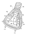
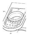
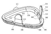
改良したクッション/シェル接続機構が、図A1およびA9aを参照して、図F44に示されている。本発明のシェル40は、クッション側の周辺部を通るチャネル500を備えている。チャネル500は、シェル40の表面52によって形成された内壁502、外壁504およびチャネルフロア506によって囲まれている。チャネル500は、シェル40の略三角形、あるいは他の適した形状に構成されており、チャネルの側壁にこすることなくチャネルにクッションを挿入することができるだけ十分に広いことが好ましい。図A9aを参照。チャネル500は、シェル40の表面52へのアクセスを可能にするようにチャネルフロア506を通る2つのスロット508を備えている。
この機構は、チャネル500とほぼ類似した形状を有するように構成された保持リング510を備えている。保持リング510は、2つのスプリングアーム513上にそれぞれ設けられた2つのクリップ512を有している。クリップ512は、保持リング510がチャネル500内に位置しているときに各クリップの下面のリップ514が表面52またはシェル40の適した部位に噛み合うように、それぞれのスロット508を通るように配置され、構成されている。各クリップの上側表面515は、取り付けられたときにスロット508を容易に通るように面取りを施されている。2つのスロット508およびクリップ512のみが示されているが、この機構は、異なる数のこのような構成要素を有してもよい。保持リング510は、保持リング510の周辺部を通り、保持リング510の底部から外側に伸びるクッション保持リップ516を有している。
【0066】
クッション30は、保持チャネル520と、チャネル520から外側に伸びる保持リップ522とを備えている。保持チャネル520および保持リップ522は、クッション30が保持リング510上に取り付けられるときに、保持リング510のクッション保持リップ516にぴったりと噛み合うように構成されている。クッション30はまた、クッション30とシェル40との間に連続した密閉した封止を提供するために、チャネル500またはクッション30の周辺部全体の周りでシェル40の他の部分に噛み合うようにクッション30から伸びているシーリングリップ524を備えている。図F44に示す実施形態では、シーリングリップ524は内壁502の外側表面、つまりチャネル500の一部分を形成している表面に噛み合う。他の実施形態では、シーリングリップ524は、内壁502の頂表面および/あるいは壁502の内側表面と密閉して噛み合うように構成されてもよい。
【0067】
クッション30をシェル40に取り付けるために、チャネル520およびリップ522を保持リップ526の周辺部で保持リップ526に噛み合わせることによって、クッションが最初に保持リング510上に取り付けられる。この手順は、いくらかの指の強さと器用さとを必要とするが、必要とされる強度および器用さは、公知のクッションおよびシェルを一緒に組み立てるための強度および器用さよりは小さい。あるいは、このアセンブリステップは、クッションの出荷に先立って工場で行われることができ、またはクッション30は保持リング510に一体的に成型されることも可能である。次に、保持クリップ512がそれぞれのスロット508に並ぶように組み立てられた保持リング/クッションアセンブリがチャネル500内に置かれ、スプリングアーム513がわずかに曲がってクリップ512がスロット508を通ることができるように保持リング/クッションアセンブリがシェル40の方に押される。クリップ512がスロット508を通過すると、スプリングアーム513は跳ね返り、クリップ512の表面514をシェル40の表面52に噛み合わせ、シェル40にクッション30を保持する。これは、クッション30のリップ522をチャネルフロア506に対してクランプで締めつけ、クッション30とシェル40との間にしっかりした封止された接続を提供するように内壁にシーリングリップ524を噛み合わせる。
クッション30をシェル40から取り外すためには、ユーザは、クリップ512がスロット508を通って戻るようにそれらがもはや表面52に噛み合っていなくなるまで、2つのクリップ512を互いに対して押すことのみを必要とする。この点において、取り外しが片手による手続きであるように、ユーザが片方の手の親指と人差し指との間に両方のクリップ512を握ることができるような距離で互いの向かいに配置された2つのみのクリップ512を有することが好ましい。このようにして、クッション/保持リングアセンブリは、クリーニングまたは他の目的のために、シェル40から容易にはずすことができる。必要ではないが、クッション30は、クリーニングのために保持リング510から取り外すことができる。
【0068】
好ましい実施形態では、保持リングはアセタールから形成されるが、他の材料を用いることもできる。さらに、チャネル500および/または保持リング510は、アセンブリ時に保持リング510をシェル40に位置合わせする際の手助けとなるキーウェイとなる特徴を備えていてもよい。
保持チャネル520および保持リップ522を通して2つの部品を内部で噛み合わせる、クッション30と保持リング510との間のサブアセンブリが示されているが、他の実施形態では、保持リング510は、適したチャネル・リップ構成で、クッションの外壁あるいは頂部壁面を通してクッション30に外部で取り付けられることができる。
図F47〜F68は、図F41〜F43に示されているラッチ機構に類似している単一のラッチ機構60を用いた本発明のマスクアセンブリ10の他の実施形態を図示している。このマスクアセンブリは、シェル40およびクッション30を備えている。図F51およびF52において、シェル40は一対のフランジアセンブリ44および46を備えている。各フランジアセンブリ44および46は、一体的に成型されたピボットピン45を備えており、2つのピボットピン45は好ましい実施形態においては互いに略平行である。
【0069】
図F58およびF55において、ラッチ機構60はさらにクリップ88およびクリップリンク240を備えている。クリップリンク240は、握り機構502を有する第1の端部500を備えている。握り機構502は、クリップリンク240をシェル40に回動可能に取り付けるために、選択されたピン45の一つに対してフィットし、それを握るために適合されている。クリップリンク240はさらに、クリップリンク240にクリップ88を回動可能に取り付けるためにクリップ88の第1の端部90で孔92に噛み合う一対のピン83を有する第2の端部504を備えている。ピン83は、クリップ2リンク240の中央部から離れる方に伸びるピンアーム85上に取り付けられており、クリップ88の孔92にピン83を挿入するためにそれらが互いの方向に曲げられ得るようにバネの作用を提供する。バネ部材506は、2つのピンアーム85を相互接続して、ピンアーム85にさらなるバネ力を与えるだけでなく、クリップリンク240のねじれに抵抗するようにピンアーム85に横方向の安定性を与える。ピンアーム85に加わる実際のバネ力は、ピンアーム85のサイズと長さと、および/またはバネ部材506のサイズと位置決めとを変更することによって、望むように変えることができる。
図F56およびF57において、ラッチ機構60はハーネスエンゲージクリップ470を備えている。ハーネスエンゲージ部470は、ハーネスエンゲージクリップ470をシェル40に取り付けるようにピン45の他のものに対してフィットするように、かつピン45の他のものを握るために適合されている握り機構514を備えている。ハーネスエンゲージクリップ470はまた、横方向のスロットの形状のマスクハーネスエンゲージ部474と、ロッキングタブ516と、ストップタブ518とを備えている。本実施形態では、ハーネスエンゲージクリップ470は、ピン45の周りを回動することを意図されていない。これは、クリップ470が所望のピン45上に搭載されたときに、ロッキングタブ516およびストップタブ518と、シェル40の隣接する表面520および522との噛み合わせによって達成される。図F58では、ハーネスエンゲージクリップ470はピン45の周りを回動することができず、ピン45に対してクリップ470の略垂直な下方への動きの使用によって、ピン45の上方に取り付けられなければならない。ロッキングタブ516はクリップ88のロッキングスロット1508を噛み合わせたり、はずしたりするように適合されている。
【0070】
好ましい実施形態では、ロッキングタブ516はロック位置でロッキングスロット1508に部分的に噛み合うのみである。このようにして、クリップ88が使用中に持ち上げられることは阻害されるが、クリップ88およびハーネスエンゲージクリップ470の自然な弾力性のために、ロッキングによる噛み合わせは、リフト部材1510に直接的なリフト力を加えることによって、ハーネスエンゲージクリップを上方の位置に回動させることなく、解消することができる。ロッキングによる噛み合わせを解消するために必要とされるリフト力の量は、ロッキングタブ516とロッキングスロット1508との間の噛み合わせの程度、および/あるいはクリップ88ならびに/またはクリップ470の剛性を変えることによって、変更することができる。ロッキングタブ516とロッキングスロット1508のロッキングエンゲージ面324は、ロック機構の容易に噛み合わせたりはずしたりすることを可能にするために、水平から角度をなしている。
他の実施形態において、ストップタブ518は取り除かれることができ、クリップ470がピン45の周りを回動することができるようにシェル40に噛み合わないように再構成することができる。この他の構成によると、この機構は、ロッキングタブ516がロッキングスロット1508に噛み合っていないロックされていない上方位置(ユーザの顔から離れる方向)と、ロッキングタブ516がロッキングスロット1508に噛み合ってクリップ88が持ち上がるのを阻害するロックされた下方位置(ユーザの顔向き)との間でピン45の周りをロッキングタブ516とハーネスエンゲージクリップ470とを回動させることによって、ロックしたり、ロックをはずしたりすることができる。このような実施形態において、ハーネスエンゲージクリップ470は、マスクアセンブリ10がマスクハーネスのテンションによって装着されたときに、ロックされた下方位置に自然に引き下げられる。このような実施形態では、ロッキングタブ516およびロッキングスロット1508は、ハーネスエンゲージクリップ470がロックされていない上方位置に回動されるまではロックによる噛み合わせが容易に解消され得ないように構成されている。好ましい実施形態では、ハーネスエンゲージクリップ470、クリップ88およびクリップリンク240は適したプラスチックからそれぞれ単一のものとして成型される。
【0071】
ヘッドサポート調節機構
図F59において、本実施形態のマスクアセンブリはまた、シェル40のエアチューブ100にヘッドサポート522を垂直に調節可能に取り付けるヘッドサポート調節機構550を備えている。ヘッドサポート調節機構550は、エアチューブ100の対向する外側の側部に接続され、エアチューブ100に沿って軸方向に通っている一対のつめ部554を備えている。つめ部554はそれぞれ、エアチューブ100に沿って配置場所を規定するようにつめ部554に沿って間隔をあけて配置された複数のスロット556を備えている。2つのつめ部554の対応する対のスロット556は、エアチューブ100に沿って同じ高さにほぼ位置している。
また、ヘッドサポート調節機構550は、エアチューブ100およびつめ部554に対してスライド可能にフィットするように適合されているヘッドサポート552に接続されたループ部558を備えている。ループ部558とエアチューブ100との間のはまり具合は、好ましくは、ヘッドサポート552が一旦調節されたらヘッドサポート552とシェル40との間での過剰な動きおよび遊びが存在するような大きな隙間を許容することなく、ループ部558がエアチューブ100に対して容易にスライドすることができるようなものである。図F62において、大きすぎない隙間なしで所望のはまり具合を提供するために、ループ部558は、対応するつめ部554を受けるための一対のスロット部560を備えている。つめ部554とスロット部560とのこの噛み合わせは、ループ部558/ヘッドサポート552とエアチューブ100/シェル40との間の望まない回転運動を防ぐ。さらに、ループ部558は、ループ部558の内側表面564に沿って軸方向に通っている複数の持ち上がったうね562を備えている。これらのうね562はエアチューブ100に接触しており、調節機構550の調節中にエアチューブ100に沿ったループ部558の容易な動きを防ぐことができるループ部558とエアチューブ100との間の接触領域で生じる摩擦量を減少させつつ、ループ部558とエアチューブ100との間で所望のはまり具合を提供する際の手助けとなる。
【0072】
図F61において、ループ部558は、調節クリップ568を受けるように適合された横方向のスロット566を備えている。調節クリップ568は、一対のスプリングタブ572を相互に接続する半円形体570を有している。分割されたフランジ突起部574は、ループ部558の裏の部分579の孔576への挿入および、調節クリップ568をループ部558に取り外し可能に取り付けるようなループ部558の外側表面580との噛み合わせのために、半円形体570の裏側に取り付けられている。図F63において、横方向スロット566は、突起部574によってループ部558に取り付けられたときに調節クリップ568を安定させるように半円形体570の対応する外側よりの背面に噛み合わせるための一対のフォワードフェイシングショルダ578を備えている。横方向のスロット566の上側および下側の表面は、調節クリップ568に縦方向の安定性を提供するように調節クリップ568の上側および下側表面に噛み合う。あるいはクリップ568およびループ部558は、単一の一つになった構成要素として成型されることもできるが、説明した2片構成は製造がより容易である。図F64において、半円形体570の正面側582は、エアチューブ100と調節クリップ568/ループ部558との間の安定性を提供するために、エアチューブ100の裏面側と係合するようになっている。
図F61において、スプリングタブ572のそれぞれは、半円形体570の後方に配置された握り部586と、半円形体570の前方に配置されたつめ噛み合わせ部584とを備えている。このようにして、半円形体570は、ユーザが握り部586を握って押したときに、つめ噛み合わせ部584が離れるようなてことして、各スプリングタブ572に対して作用する。握り部586が開放されると、クリップ568の自然なバネ作用はつめ噛み合わせ部584を近づけるように動かす。半円形体570は、半円形体570に対するスプリングタブ572のフレキシビリティを増加させるように、その外側の縁581で薄くすることができる。調節クリップ56がループ部558に取り付けられると、つめ噛み合わせ部が横方向伸すロット566に位置している状態で、握り部586はユーザによる操作のためにループ部558の外側に配置される。
【0073】
各握り部586は、握り部586が互いに離れるように、またつめ噛み合わせ部584を互いの方向に付勢することを助けるようにループ部558の外側の表面に噛み合うためのスプリングアーム588を備えている。各つめ噛み合わせ部584は、エアチューブ100/シェル40に対してループ部558/ヘッドサポート552を縦方向にロックするためにつめ部554の対応するスロットに噛み合うようなサイズで適合された噛み合わせタブ590を備えている。ループ部558/ヘッドサポート552の位置決めは、スロット56から噛み合わせタブ590を解消するように握り部586を一緒に締め付け、エアチューブ100上の所望の位置にループ部558を動かして、網合わせた部がつめ部554の対応するスロット556に噛み合うように握り部586を開放することによって、エアチューブ100/シェル40に対して調節することができる。示されているこの実施形態では、4セットのスロット556があり、したがって、エアチューブ100に対してループ部558が調節され得る縦方向の位置が4つあることになる。スロットの数は、調節位置の数を他の数とするために変更することができる。
【0074】
図F60において、ヘッドサポート552は、ヘッドサポート552を対応するマスクハーネスに取り付けるための複数のスロット592または他の噛み合わせ機構と、患者の頭部に噛み合ってヘッドサポート552を安定させるループ部552を有している。図示されていないが、ヘッドサポート552、特にループ部553、およびマスク10の他の構成要素は、患者に対してクッション性のあるより快適なフィット感を与えるために発泡体、布地、または他の柔らかい材料で覆われてもよい。
エアチューブ100はシェル40の面に対して略平行に並べられているものとして図示されているが、エア供給導管との接続に対してよりよい位置合わせを提供するために、エアチューブ100は後方へユーザ向きにいくらか角度をなしていてもよい。本実施形態によると、エアチューブ10を後方に最大18°まで、好ましくは約10°傾けることによって、エア供給導管との所望の位置合わせが得られ、ユーザの快適なフィット感が得られる。状況が許すのであれば、他の角度とすることもできる。
【0075】
呼気ポート
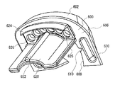
図F52において、シェル40は、吸入ポート102の中央外側に配置された単一の呼気ポート106を備えている。図A9bに示す実施形態とは異なり、本実施形態では、シェル40の呼気通路はシェルの厚さと同様の長さであるので呼気ダクトはない。呼気ポート106の外側は上方に向けられており、エアチューブ100を部分的に取り囲んでいる。図F47を参照。呼気ポート106は所望の流量に対して適切なサイズであれば単独で使用することができるが、図F65およびF66または図F59に図示されているように付加的な呼気ベント600とともに使用されることが好ましい。図F59はシェル40上に取り付けられたベント600を示している。ベント600は概してフレキシブルであり、好ましくはシリコーンから成型されるが、他の材料を用いることもできる。
【0076】
ベント600は、上側表面604と下側表面606とを有するボディ602を備えている。ボディ602は、ベント600をシェル40に固定するためにエアチューブ100を受けて握るようにサイズを決められて構成された略半円形の切り取り608を備えている。半円形の切り取り608は、一対の軸方向に伸びるスロット610を有している。スロット610は、2つのつめ部554を受け、かつベント600とエアチューブ100との間に付加的な握り力を与えるように構成されている。ボディ602はまた、一対の傾斜のついた持ち上がっているウィング612を有している。ウィング612は、エアチューブ100と接触してエアチューブ100とシェル40との間に付加的な握り力と美的な変わり目を提供するように半円形の切り取り608の外よりの端部上に配置されている。下側表面606は、シェル40に取り付けられると、シェル40の上方を向いたベントプラットフォーム614上におさまるように適合されている。
バッフル620は、ベント600の下側表面606に接続されて、そこから下方に伸びている。バッフル620は、呼気ポート106内に伸び、シェル40の内部に伸びて、マスク内の吸入流と排出流とを分離し続ける助けとなる。これにより、周期的な雑音は減少し、マスクからの排出気体の除去が向上される。バッフル620は、バッフル620に剛性および強度を付加する軸方向に伸びているリブ622を備えている。バッフル620は、平坦な外側よりの部分と有する略半円形の断面を有するものとして図示されているが、異なる流れの特徴のために望まれるのであれば、その形状を変更することもできる。図F65において、バッフル620から間隔をあけて配置されたフランジ624もベント600の下側表面606に接続されて、そこから下方に伸びている。フランジ624およびバッフル620は、呼気ポート106の内部側に接触して、シェル40および呼気ポート106に対してベント600を正しく位置決めすると同時に、シェル40にベント600を固定する助けとなるように構成されている。
【0077】
複数のベント開口部626が、呼気を大気中に出すためにバッフル620とフランジ624との間に配置されている。ベント開口部626の数、およびそれらのサイズと形状とは、異なる流れの特性を獲得するために望まれれば変更することができる。しかしながら、示されている好ましい実施形態においては、6個の開口部626があり、それぞれはベント600の内側から外側へ、開口部の長さの少なくとも一部にわたって傾斜している。つまり、ベント開口部626の内側は、開口部626の外側よりも大きい。このような構成により、呼気の流れによって生じる雑音を低減することができる。
各ベント開口部626の長さは、開口部の流れ特性に影響を与え得、ベント開口部626の領域におけるベントボディ602の厚さによって決定される。ベント開口部626の長さを好ましい3.6mmまで減少させるために、ベントボディ602は、ベントボディ602の上側表面604上にベント開口部626を囲むくぼみ628を有しており、これがベント開口部626の領域におけるベントボディ602の厚さを減少させる。くぼみ628は、他の構成を有することもでき、ベントボディ602の下側表面606に配置されることもでき、ベントボディ602の上側および下側表面の両方上に配置することさえも可能である。ベント開口部626の長さは、ベント開口部626の領域におけるベントボディ602の厚さを変えるようにベントボディ602のどちらかの側にある1以上のくぼみを用いることによって、望む通りに変更することができる。ベント開口部の長さに影響を及ぼすようにベントボディ602の全体の厚さも望む通りに変えることができるが、ベント600に必要な剛性を与えてシェル40上の所望の位置にとどまらせるためには、ある最小の厚さが一般的には好ましい。したがって、くぼみを使用することによって、所望のベント開口部の長さを提供しながら、全体のベントの厚さを所望の最小の厚さに合わせることができる。くぼみの構成は、ベント開口部626とともに働いてベント600に異なる流れ特性を与えるように変更することも可能である。ベント600を成型するために必要な材料の量を減らすために、他のくぼみ630も、ベント600の堅さがより問題とならないようなベントボディ602上のどこかに配置されることができる。
【0078】
クッション/シェル接続機構
本実施形態のマスクアセンブリは、図F44に示された機構と類似したクッション/シェル接続機構を用いている。図F47、F52、F67およびF68を参照。図F52において、シェル40はクッション側の周辺部を通るチャネル500を有している。チャネル500は、内壁502、外壁504およびシェル40の表面52によって形成されたチャネルフロア506に囲まれている。チャネル500は、シェル40の略三角形の形状に構成されている。チャネル500は、チャネルフロア506を通ってシェル40の表面52へのアクセスを可能にする2つのスロット508と、三角形の底部の外壁504に第3のスロット509とを備えている。第3のスロット509は、スロット508に対して略90°をなしてチャネル500の外壁504を貫いて伸びる。
【0079】
図F67において、この機構は、チャネル500とほぼ同様な形状を有するように構成された保持リング510を備えている。保持リング510は、2つのスプリングアーム513上にそれぞれ配置された2つのクリップ512を有している。クリップ512は、保持リング510がチャネル500内に位置しているときに各クリップ512の下側のリップ514が表面52にはまるようなスロット508をそれぞれが貫通するように配置され、構成されている。図F67において、各クリップ512の上側表面515は、スロット508を容易に通ることができるように円味をつけられている。保持リング510はまた、保持リング510の残る第3の辺上に配置された保持タブ511を有している。保持リング510の第3の辺は、クリップ512を有していない。保持タブ511は保持リング510から外側に、クリップ512がほぼ伸びている面に対して90°をなす面内をほぼ伸びている。保持タブ511は、保持スロット508にはまるように適合されている。
図F67において、保持リング510は、下側保持リップ640、上側保持リップ642およびそれらの間に設けられたチャネル644を有しており、これらは全て保持リング510の周辺部を通る。各クリップ512の側部上のノッチ646は、クリップ512のフレキシビリティを増加させるために上側リップ642を切り通してチャネル644に達している。
図F68において、クッション30は、保持チャネル520と、チャネル520から外側に伸びている保持リップ522とを備えている。保持チャネル520は、保持リング510の下側保持リップ640にぴったりと噛み合うように構成されており、保持リップ522は、クッション30が保持リング510に取り付けられたときに下側リップ640と上側リップ642との間の保持リングチャネル644にぴったりと噛み合うように構成されている。また、クッション30は一対のシーリングリップ524を有しており、これらは、クッション30の内側の周辺部全体の周りでチャネル500の内壁502に噛み合うようにクッション30から伸びており、クッション30とシェル40との間に連続した密閉された封止を提供する。シーリングリップ524は、クッション30がシェルに取り付けられるときにあると思われる位置で図示されているが、シェル40からクッション30がとりはずされるときには開放状態に戻る。このフレキシブルシーリングリップ524の変形によって、クッション/保持リング/保持クリップには取り付けられたときにテンションがかかり、接続機構とシェル40との間でしっかりした接続を維持するための助けとなる。1以上のシーリングリップ324を用いてもよい。
【0080】
本実施形態は、図F44に示されている実施形態がしているように保持リング510とチャネルフロア506との間にクッション30の一部をクランプで固定したりはせずに、クッション30とシェル40との間に密閉された封止を提供するためにはシーリングリップ524とシェル40との間の接触のみに頼る。本実施形態では、保持リング/クッションアセンブリはチャネル500内に角度をなして配置され、保持タブ511が保持スロット508に噛み合うことができるように、チャネル500内の三角形の底辺および三角形の上の2つの辺はチャネル500の外側にわずかに回動されている。そして、保持リング/クッションアセンブリ510は、保持リングの残りの部分がチャネル500内に動き、クリップ512がスロット508に噛み合って保持リング510をシェル40に対して所定の位置に配置するように、シェル40側に上方に回動される。このようにして、保持タブ511および保持スロット508は、図F44に示されている実施形態と比較して、持リング510の底辺で保持リング510とシェル40との間に付加的なクランプ力を提供する。とりはずしは、図F44に示されている実施形態と同様に、クリップ512を一緒に締め付けて、保持タブ511が保持スロット509からはずれることができ、かつ保持リング/クッションアセンブリが完全にシェル40からはずれることができるまで保持リング510をチャネル500の外側に回動させることによって行われる。
図F50において、シェル40は一対の間隔をあけて配置された下方に突出しているアクセスポート118を備えている。このアクセスポート118は、上述したように、シェル40の底部に位置するくぼみ592内に配置されている。
【0081】
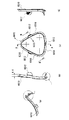
図F69(a)〜F69(d)は、本発明の他の実施形態における保持リング6010の複数の図である。図F69(c)の正面図に示されているように、保持リング6010は、略三角形の形状を有しており、2つのクリップ部6012と保持タブ6013とを備えている。保持リング6010は、ベース6014と2つの辺6016を有している。図69(c)に示されている略三角形以外の形状を用いてもよく、同様に辺6016の数は2つ以外でもよい。
図F69(b)およびF69(d)に示されているように、クリップ部6012は保持リング6010から出て伸びている。クリップ部6012は、それぞれ矢印6020または6022の方向に外側または内側に弾性的に曲がるように適合されていてもよい。図F69(b)は図F69(c)の基準線A−Aに沿った保持リング6010を示している。図F69(d)は保持リング6010の右側面図である。図F69(a)は、図F69(c)の基準線B−Bに沿った保持リング6010を示している。、
【0082】
図F70(a)〜F70(c)は保持リング6010の複数の等角図を示す。図F70(a)において、保持リング6010は、外側表面7006と内側表面7008とを有する正面に突出した壁7004を有している。図F70(b)の下側の等角図では、クリップ部6012は、ユーザの指への握り面を提供するためのうねのある表面を備えている。図F70(c)は、クリップ部6012のうねのある表面の拡大した詳細図を示している。
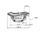
図F71はクリップ部6012の詳細図を示す。クリップ部6012は、77°〜97°の範囲の角度で、好ましくは87°の角度で保持リングから突出している。
図F72は、2つのクリップ部6012と、保持タブ6013とを有する保持リング6010の下側から見た図である。保持リング6010は、94.00mm〜114.00mmの範囲、好ましくは104.00mmの曲率半径を有している。
【0083】
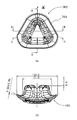
図F73(a)およびF73(b)は、それぞれ、クリップ部6012と保持タブ6013とを有する保持リング6010の上面図および裏面図である。
図F74は、図F69(c)の基準線B−Bに沿ったクッション7402の斜視図であり、クッション7402は88°〜108°の範囲、好ましくは98°の曲率半径を有している。
図F75は、図F69(c)の基準線A−Aに沿ったクッション7402の斜視図である。
図F76(a)およびF76(b)は、それぞれ、クッション7402の側面図および下面図である。
図F77(a)はガセット部7404を有するクッション7402を示す。図F77(b)は、図F77(a)の基準線C−Cに沿ったガセット部7404の詳細図である。
図F78(a)および図F78(b)は、42.0mm〜62.0mmの範囲、好ましくは52.0mmの厚さを有するクッション7402の正面図および側面図である。
図F79は、クッション7402およびクリップ部6012の断面図である。
【0084】
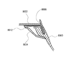
図F80は、本発明のマスクアセンブリの他の実施形態の分解側面図である。マスクアセンブリ8001は、クッション8000、保持リング8002およびシェル8004を有している。シール形成膜8006を有しているクッション8000と、ガセット部8008とは、クッション8000のショルダ部8010に保持リング8022のフランジ部8016および8032をはめ込むことによって、保持リング8002の周りに取り付けられる。クッションおよび保持リングアセンブリは、クリップ部8012をシェル8004のスロット部8020に挿入してシェル8004の下側に噛み合わせることによって、シェル8004に挿入される。スロット部8020はシェル8004の内壁内に配置されている。図F80に示されているのは1つのスロット部8012とクリップ部8012であるが、1以上のクリップ部およびスロット部を用いてもよい。
図F81は、図F80の実施形態のクッションおよびリングアセンブリ8100の正面図であり、2つのクリップ部8012と保持タブ8013とを有している。図F82は、図F81のクッションおよびリングアセンブリ8100の基準線A−Aに沿った分解断面図である。
【0085】
図F83は、図F80のシェル8004の横から見た断面図である。図F83において、シェル8004は、クッションおよびリングアセンブリのクリップ部8012がシェル8004の内壁8022と外壁8034との間でスロット8020を通って受け止められるような内壁8022および外壁8034を有している。
図F84は図F80およびF83のシェル8004の背面図を示しており、チャネル8036はシェル8004の外壁8034と内壁8022との間に配置されている。シェル8004は、クッションおよび保持リングアセンブリからのクリップ部と保持タブとを受けるための3つのスロット部8020を有している。
図F85は3つのスロット8022を有するシェル8022の正面図と、基準線B−Bとを示している。図F86は図F85の基準線B−Bに沿ったクッションおよび保持リングアセンブリならびにシェルの断面図を示す。
図F87は、図F80のマスクアセンブリ8001の側面図を示す。図F88およびF89は、フランジ部8040を有する上側および下側クリップ部8012の断面を示している。図F87において、マスクアセンブリ8001は、シェルに挿入された、完全に組み立てられたクッションおよび保持リングアセンブリだけでなく、ヘッドマウント部8701おおよびエアインレット部8705を有している。ヘッドマウント部8701は、ユーザ上でマスクアセンブリを安定させるための機構8703を備えている。
図F80〜F82は、シェルの内壁に挿入されたクッションおよびリングアセンブリの断面図を示す。クッションおよび保持リングアセンブリのクリップ部8012は、シール形成部8006によってシェルにしっかりと固定される。図F90は、図F81における基準線90−90に沿った、シェルに挿入されたクッションおよび保持リングアセンブリを示している。図F91は、図F81における基準線91−91に沿った、シェルに挿入されたクッションおよびリングアセンブリを示している。図F92は、図F81における基準線92−92に沿った、シェルに挿入されたクッションおよびリングアセンブリを示している。
【0086】
様々な上述した実施形態の構成要素、要素および特徴は、新しいマスクの実施形態を作り出すためにいかなる所望の組み合わせまたは置換の中で一緒に用いることができる。例えば、本発明は、鼻用マスクに関連して説明したが、この教示は鼻/口用マスクにも同様に適用可能である。
以上、本発明を実施の形態を用いて説明したが、本発明の技術的範囲は上記実施の形態に記載の範囲には限定されない。上記実施の形態に、多様な変更又は改良を加えることができる。その様な変更又は改良を加えた形態も本発明の技術的範囲に含まれ得ることが、特許請求の範囲の記載から明らかである。
【図面の簡単な説明】
【図A1】 本発明のマスクアセンブリの斜視図である。
【図A2】 図A1のマスクアセンブリのシェルの正面斜視図である。
【図A3】 図A1のマスクアセンブリのラッチ機構の一部の平面図である。
【図A4】 図A3のラッチ機構の一部の斜視図である。
【図A5】 図A3のラッチ機構のクリップリンクの斜視図である。
【図A6】 図A3のラッチ機構のクリップピンの斜視図である。
【図A7】 図A1のマスクアセンブリのラッチ機構のクリップ部の斜視図である。
【図A8a】 図A1のマスクアセンブリのラッチ機構に働く力を示す模式図である。
【図A8b】 図A1のマスクアセンブリのラッチ機構に働く力を示す模式図である。
【図A8c】 図A1のマスクアセンブリのラッチ機構に働く力を示す模式図である。
【図A9a】 図A2のシェルの背面斜視図である。
【図A9b】 図A2のシェルの他の実施形態の断面図である。
【図A10】 本発明のマスクアセンブリの部分切欠側面図である。
【図A11】 図A10のマスクアセンブリのヘッドマウントの一部の底背面斜視図である。
【図A12】 本発明のボール・ソケットジョイントを示す。
【図A13】 本発明のボール・ソケットジョイントを示す。
【図A14】 本発明のボール・ソケットジョイントを示す。
【図A15】 本発明のボール・ソケットジョイントを示しており、図A14の詳細図である。
【図A16】 本発明のボール・ソケットジョイントを示す。
【図A17】 本発明のシェルの他の実施形態の背面斜視図である。
【図A18】 図A17のシェルの他の実施形態および本発明のラッチ機構のほかの実施形態の正面斜視図である。
【図A19】 図A18のラッチ機構のクリップの斜視図である。
【図A20】 本発明のシェルの他の実施形態の正面斜視図である。
【図A21】 本発明のシェルの他の実施形態の上面からみた斜視図である。
【図F1】 ユーザに取り付けられた、本発明のマスクアセンブリの他の実施形態の斜視図である。
【図F2】 図F1のマスクアセンブリの側面図である。
【図F3】 図F1のマスクアセンブリの正面斜視図である。
【図F4】 図F1のマスクアセンブリのヘッドストラップの斜視図である。
【図F5】 図F1のマスクアセンブリのシェルの背面斜視図である。
【図F6】 図F5のシェルの正面斜視図である。
【図F7】 図F1のマスクアセンブリのラッチ機構のクリップ部の斜視図である。
【図F8】 図F1のマスクアセンブリのラッチ機構の単一のクリップ部の斜視図である。
【図F9a】 図F1のマスクアセンブリのソケットの斜視図である。
【図F9b】 図F1のマスクアセンブリのボールの側立面図である。
【図F10】 本発明のマスクアセンブリのヘッドマウント調節機構の他の実施形態の斜視図である。
【図F11】 図F10のヘッドマウント調節機構の側立面図である。
【図F12】 図F10のヘッドマウント調節機構の動作を示す正面図である。
【図F13】 本発明のマスクアセンブリのヘッドマウント調節機構の他の実施形態の斜視図である。
【図F14】 図F13のヘッドマウント調節機構の詳細を示す拡大斜視図である。
【図F15】 本発明のマスクアセンブリのシェルの他の実施形態に搭載された図F13のヘッドマウント調節機構の背面斜視図である。
【図F16】 図F15のヘッドマウント調節機構およびシェルの側面斜視図である。
【図F17】 図F15のヘッドマウント調節機構およびシェルの正面図である。
【図F18】 図F15のヘッドマウント調節機構およびシェルの側立面図である。
【図F19】 本発明のマスクアセンブリの他の実施形態のシェルに搭載されたヘッドマウント調節機構の他の実施形態の正面斜視図である。
【図F20】 図F19のヘッドマウント調節機構およびシェルの詳細を示す斜視図である。
【図F21】 図F19のヘッドマウント調節機構およびシェルの背面から見た分解図である。
【図F22】 図F19のヘッドマウント調節機構およびシェルの正面から見た分解図である。
【図F23】 図F19のヘッドマウント調節機構の一部の側立面図図である。
【図F24】 図F19のヘッドマウント調節機構の一部の正面斜視図である。
【図F25】 図F19のヘッドマウント調節機構の連結ブラケットの正面図である。
【図F26】 図F25の連結ブラケットの側面図である。
【図F27】 図F25の連結ブラケット背面斜視図である。
【図F28】 図F19のヘッドマウント調節機構のロックブラケットの正面斜視図である。
【図F29】 図F28のロックブラケットの正面図である。
【図F30】 図F28のロックブラケットの側面図である。
【図F31】 本発明のマスクアセンブリの他の実施形態の斜視図である。
【図F32】 図F31のマスクアセンブリの側面図である。
【図F33】 本発明のラッチ機構の他の実施形態の正面図である。
【図F34】 図F33のラッチ機構が閉止位置にある状態の底部の立面図である。
【図F35】 図F33のラッチ機構が開放位置にある状態の底部の立面図である。
【図F36】 本発明のラッチ機構の他の実施形態の正面図である。
【図F37】 図F36のラッチ機構が閉止位置および開放位置にある状態のラッチ機構の底部の立面図である。
【図F38】 本発明のマスクアセンブリの他の実施形態の斜視図である。
【図F39】 図F38のマスクアセンブリの側面図である。
【図F40】 図F38のマスクアセンブリの正面図である。
【図F41】 部分的開放位置にあるラッチ機構の他の実施形態の正面斜視図である。
【図F42】 図F41のラッチ機構の閉止位置にあるときの正面斜視図である。
【図F43】 図F41のラッチ機構の部分的開放位置にあるときの背面斜視図である。
【図F44】 クッションをシェルに固定するために用いられる機構の断面図である。
【図F45】 ユーザに取り付けられた図F38のマスクアセンブリの正面図である。
【図F46】 ユーザに取り付けられた図F38のマスクアセンブリの側面図である。
【図F47】 本発明のマスクアセンブリの他の実施形態の斜視図である。
【図F48】 図F47の実施形態の正面立面図である。
【図F49】 図F47の実施形態の側面立面図である。
【図F50】 図F47の実施形態の底部斜視図である。
【図F51】 図F47の実施形態のマスクシェルの正面斜視図である。
【図F52】 図F47の実施形態のマスクシェルの背面斜視図である。
【図F53】 図F47の実施形態のラッチ機構のクリップの正面斜視図である。
【図F54】 図F53のクリップの背面斜視図である。
【図F55】 図F47の実施形態のラッチ機構のクリップリンクの背面斜視図である。
【図F56】 図F47の実施形態のラッチ機構のハーネス噛み合わせクリップの背面斜視図である。
【図F57】 図F47の実施形態のラッチ機構のハーネス噛み合わせクリップの正面斜視図である。
【図F58】 図F47の実施形態のラッチ機構およびマスクシェルの断面図である。
【図F59】 図F47の実施形態の斜視図である。
【図F60】 図F47の実施形態のヘッドサポートの斜視図である。
【図F61】 図F47の実施形態のヘッドサポート調節機構の調節クリップの斜視図である。
【図F62】 図F47の実施形態のヘッドサポート調節機構の一部の斜視図である。
【図F63】 図F47の実施形態のヘッドサポート調節機構の一部の底部斜視図である。
【図F64】 図F47の実施形態のヘッドサポート調節機構の一部の断面図である。
【図F65】 図F47の実施形態のベントの底部斜視図である。
【図F66】 図F65のベントの上面から見た斜視図である。
【図F67】 図F47の実施形態のクッション/シェル接合機構の保持リングの斜視図である。
【図F68】 図F47の実施形態のクッション/シェル接合機構の保持リングの部分断面図である。
【図F69】 (a)〜(d)は本発明の他の実施形態における保持リングの複数の図である。
【図F70】 (a)〜(c)は図F69(a)〜(d)の保持リングの等角図である。
【図F71】 図F69(a)〜(d)の保持リングのクリップ部の詳細を示す図である。
【図F72】 図F69(a)〜(d)の保持リングおよびクリップ裏面図である。
【図F73】 (a)および(b)は図F69(a)〜(d)の保持リングの上面および背面図である。
【図F74】 本発明の他の実施形態におけるクッションの斜視図である。
【図F75】 図F74のクッションの側面図である。
【図F76】 (a)および(b)は図F74のクッションの側面立面図である。
【図F77】 (a)および(b)は図F74のクッションの正面図および斜視図である。
【図F78】 (a)および(b)は図F74のクッションのさらなる正面図および斜視図である。
【図F79】 図F74のクッションの断面図である。
【図F80】 本発明の他の実施形態の分解側面図である。
【図F81】 図F80における実施形態のクッションおよびリングアセンブリの正面図である。
【図F82】 図F81のクッションおよびリングアセンブリの分解図である。
【図F83】 図F80の他の実施形態におけるマスクの側部断面図である。
【図F84】 図F83のマスクの背面図である。
【図F85】 図F83のマスクの正面図である。
【図F86】 図F85の基準点B−Bに沿ったマスクおよびリングアセンブリを示す図である。
【図F87】 図F80の他の実施形態の側面図である。
【図F88】 図F80の実施形態における上方のつめの断面図である。
【図F89】 図F80の実施形態における下方のつめの断面図である。
【図F90】 図F80に示されているマスクアセンブリの他の実施形態の断面図である。
【図F91】 図F80に示されているマスクアセンブリの他の実施形態の断面図である。
【図F92】 図F80に示されているマスクアセンブリの他の実施形態の断面図である。
【符号の説明】
10 マスクアセンブリ
20 シェルアセンブリ
30 クッション
40 シェル
44、46 フランジアセンブリ
60 ラッチ機構
62、64 クリップリンク
70 ピボットピン
83 ピン
85 ピンアーム
88 クリップ
96 ハーネス係合部
98 フリップアーム
100 エアインレットチューブ
102 エアインレットチューブ開口ポート
104 呼気ダクト
118 アクセスポート
120 排出ポート
130 ヘッドマウント
134、136 スロット
140 ヘッドマウント高アジャスタ
142 エアコネクタチューブ
146 アジャスタ
152 フィンガーホイール
162 フランジ
200 ボール・ソケットジョイント
204 ボール
208 ソケット
214 エアコネクタチューブ
220 延長ブラケット
224 ヘッドストラップ
230、231 調節スロット
240 クリップリンク
245 延長タブ
250 ヘッドマウント調節機構
252 スプリングタブ
254 ロッキングギア
256 ロッキング歯
266 ブラケット
268 スロット
270 ロッキング歯
271 ピンアーム
282 バッフル
300 ヘッドマウント調節機構
304 ヘッドマウント部
306 ロッキングブラケット
308 保持チャネル
312 接続ブラケット
316 スプリングアーム
320 ヘッドマウント
334 ヘッドストラップ
340 接続フランジ
360 ヘッドストラップアセンブリ
362 背面ヘッドストラップ
364 頭部マウント
370 保持チャネル
380 マウントプレート
400 ラッチ機構
402 リンク
404 リンクアーム
410 ハーネスストラップ
420 ラッチ機構
450 ヘッドストラップ
452 正面ハーネスマウント
454 上部ヘッドマウント
456 上部ハーネスマウント
458 スロット
461 ハーネス
470 ハーネスエンゲージクリップ
500 チャネル
506 チャネルフロア
510 保持リング
513 スプリングアーム
516 ロッキングタブ
520 保持チャネル
524 シーリングリップ
550 ヘッドサポート調節機構
552 ヘッドサポート
600 ベント
602 ボディ
612 ウィング
620 バッフル
626 ベント開口部
6010 保持リング
7402 クッション
7404 ガセット部
8000 クッション
8001 マスクアセンブリ
8002 保持リング
8004 シェル
8008 ガセット部
8022 内壁
8034 外壁
8036 チャネル
8100 クッションおよびリングアセンブリ[0001]
BACKGROUND OF THE INVENTION
The present invention relates to a mask assembly used to deliver non-invasive positive airway pressure (NPPV) for the treatment of sleep breathing disorders (SDB).
[0002]
[Prior art]
The application of continuous positive airway pressure (CPAP) to the treatment of obstructive sleep apnea syndrome (OSA) was first reported in US Pat. No. 4,944,310 (Sullivan) by Sullivan. In CPA treatment of OSA, the pressure of pressurized air or other breathable gas raised above atmospheric pressure, typically 4-20 cmH2Supplied to the patient's airway entrance in the range of O and opens the patient's airway "with splint" to prevent obstructive apnea. An apparatus for reaching NPPV therapy typically includes a blower, a delivery conduit, and a patient interface. The blower may be programmed to deliver a range of different forms of treatment.
[0003]
In one form, a constant pressure of air or breathable gas is supplied to the patient. A form of CPAP known as self-adjusting nasal CPAP treatment, which is also known to vary the level of treatment pressure from breath to breath as needed by the patient, as described in US Pat. No. 5,245,995 (Sullivan and Lynch) Configure. In other configurations, a relatively high pressure gas may be supplied to the patient's mask during the inspiratory phase of respiration and a relatively low pressure or atmospheric pressure may be supplied to the patient's mask during the expiratory phase of respiration. In other modes, pressure is varied in a complex manner throughout the respiratory cycle. For example, the pressure of the mask during inspiration or expiration can be returned throughout the treatment period. See, for example, US Pat. No. 5,704,345 and International Patent Publication Nos. WO98 / 12965 and WO99 / 61088. All of these are incorporated herein. As used herein, the term NPPV treatment will be used to encompass all of these forms of treatment.
The patient interface may be in many shapes such as a nasal mask assembly, a nasal and mouth mask assembly or a nasal prong assembly. A mask assembly typically but not always has a hard shell, a soft face contact cushion, and a forehead support and headgear that secures the mask to the head.
[0004]
In one known mask assembly, the headgear has a cap portion having four straps. In use, the cap restrains the patient's back of the head. In use, the lower two straps extend between the cap portion and the nose mask, and the upper two straps extend between the cap portion and the forehead support.
Some patients have a quick release mechanism. Since the patient must be able to sleep with the interface on, it must be comfortable to wear. Also, the patient interface must provide a good seal to minimize any unintended air leaks that occur and to control any intended air leaks. Since the shape of the human nose, face and head varies widely, it is important to produce a patient interface that can accommodate this range of shapes without causing excess inventory from a commercial perspective. Numerous patient interfaces have been designed with the goal of patient comfort, ease of use, adjustment capabilities, and the ability to accommodate a wide range of patient face and head shapes.
[0005]
US Pat. No. 5,243,971 (Sullivan and Bruderer) provides a nasal mask suitable for use in CPAP or NPPV therapy. The mask has a face contact applied to a shell that is sized and shaped to fit over the intended wearer's nose area, and the face contact is elastomeric. It is in the form of an inflatable membrane molded from the material. The inflatable membrane and shell define a chamber and the membrane is inflated outward from the shell by a pressurized gas that is allowed to enter the chamber. When placed in contact with the wearer's face, this inflatable membrane covers the face area to be covered and conforms three-dimensionally to the contour of the covered area under the influence of pressurized gas. To do. The opening is formed in the membrane and is arranged and shaped to guide gas from the chamber to the wearer's nasal cavity. The content of this patent is incorporated as a cross reference.
[0006]
US Pat. No. 6,112,746 (Kwok and Styles) describes a nasal cushion comprising a frame having a substantially triangular shape, from which a membrane extends. The frame has a corrugated end whereby the cushion is affixed to the mask body. The membrane has an opening that receives the wearer's nose. This membrane is separated from the rim of the frame and its outer surface has substantially the same shape as the rim. Each notch receives the wearer's nose bridge. The wearer's nose enters the chamber through the opening and is received by the mask body. Thus, the seal-forming part contacts both the wearer's nose surface, between the nose root and upper lip of the wearer's face, and around the side of the nose bridge and part of the area on the bridge. The shape of the seal formation is particularly adapted to effectively seal areas with difficult facial contours, such as wrinkles between the side of the nose and the face. The contents of this patent are incorporated herein by reference.
[0007]
US Pat. No. 6,119,683 (Kwok, Matchett and Grant) describes an adjustable forehead support for a nasal mask. It is described that the adjustable forehead support for nasal or full face masks can be adjusted for facial profiles of different shapes and sizes. The forehead support employs a dual arm system that adjusts the position of the forehead support with respect to the mask and / or airflow tube. The angle of the mask relative to the face can be adjusted by the invention of the '693 patent. The contents of this patent are incorporated herein by reference.
[0008]
International patent application PCT / AU00 / 00097 (WO 00/78384) discloses a forehead support adapted to be secured to a respiratory mask. The forehead support includes a connecting member that fixes the mask and a cushion frame that is rotatably attached to the connecting member. The cushion frame is adapted to place one or more forehead cushions. The cushion frame is adapted to rotate relative to the connecting member. In one embodiment, the cushion frame can be selectively disposed at two or more predetermined angular positions with respect to the connecting member. A respiratory mask assembly having a respiratory mask and a forehead support adapted to be secured to the mask is also disclosed. The contents of this specification are hereby incorporated by reference as a cross reference.
[0009]
Pending US application Ser. No. 09 / 482,718 (Lithgow) describes a headgear for securing a respiratory mask to a patient having a quick release configuration. The headgear has at least one strap extending from each side of the mask, and the strap is releasably tightened behind the patient's face to secure the mask. The headgear further has a pull-shaped release means. The pull cord is attached to the upper strap in the area where the overlying strap is attached to the lower strap and is guided forward so that it can be grasped on the front of the patient. The contents of this application are hereby incorporated by reference as cross references.
[0010]
A mask cushion for use with a mask assembly in NPPV treatment is disclosed in US Patent Application No. 09 / 885,445 “Masseted Mask”, filed Jun. 21, 2001 and assigned to the assignee of the present application. Yes. This application is hereby incorporated by reference. The mask system disclosed herein has a suspension mechanism that allows relative movement between the cushion in contact with the face and the mask shell. The suspension mechanism also provides a predetermined force on the cushion that is a function of mask pressure, cushion displacement, or both. In one embodiment of the invention, the mask cushion assembly has an inflatable gusset that acts as a suspension mechanism.
The following documents have been found or submitted in foreign patent applications corresponding to this application.
[Patent Document 1]
US Patent Application Publication No. 2003/0075180
[Patent Document 2]
US Pat. No. 10,871,745
[Patent Document 3]
US Pat. No. 4,676,241
[Patent Document 4]
U.S. Pat. No. 4,713,844
[Patent Document 5]
US Pat. No. 4,944,310
[Patent Document 6]
US Pat. No. 5,243,971
[Patent Document 7]
US Pat. No. 5,245,995
[Patent Document 8]
US Pat. No. 5,414,046
[Patent Document 9]
US Pat. No. 5,704,345
[Patent Document 10]
US Pat. No. 5,912,239
[Patent Document 11]
US Pat. No. 6,112,746
[Patent Document 12]
US Pat. No. 6,119,693
[Patent Document 13]
US Pat. No. 6,347,631
[Patent Document 14]
US Pat. No. 6,412,487
[Patent Document 15]
US Pat. No. 6,422,238
[Patent Document 16]
US Pat. No. 6,530,373
[Patent Document 17]
US Pat. No. 6,536,435
[Patent Document 18]
US Patent Application Publication No. 2002/0029780
[Patent Document 19]
US Pat. No. 5,349,949
[Patent Document 20]
US Pat. No. 6,615,832
[Patent Document 21]
US Patent Application Publication No. 2002/0096175
[Patent Document 22]
US Pat. No. 6,467,483
[Patent Document 23]
US Pat. No. 5,724,965
[Patent Document 24]
US Pat. No. 4,905,686
[Patent Document 25]
U.S. Pat. No. 4,811,730
[Patent Document 26]
US Pat. No. 1,070,986
[Patent Document 27]
German utility model No. 29723101 specification
[Patent Document 28]
International Publication No. 98/12965 Pamphlet
[Patent Document 29]
WO99 / 61088 pamphlet
[Patent Document 30]
International Publication No. 00/78384 Pamphlet
[Patent Document 31]
International Publication No. 87/01950 Pamphlet
[Patent Document 32]
European Patent Application No. 1027905
[Patent Document 33]
European Patent Application No. 1057494
[Patent Document 34]
US Patent Application Publication No. 2004/0134497
[Patent Document 35]
US Patent Application Publication No. 2002/0023650
[Patent Document 36]
US Patent Application Publication No. 2002/0023649
[Patent Document 37]
US Pat. No. 2,029,129
[Patent Document 38]
US Pat. No. 2,359,506
[Patent Document 39]
US Pat. No. 2,371,965
[Patent Document 40]
US Pat. No. 2,823,671
[Patent Document 41]
US Pat. No. 2,893,387
[Patent Document 42]
US Pat. No. 3,189,027
[Patent Document 43]
US Pat. No. 3,474,783
[Patent Document 44]
U.S. Pat. No. 4,121,580
[Patent Document 45]
U.S. Pat. No. 4,226,234
[Patent Document 46]
US Pat. No. 4,274,404
[Patent Document 47]
US Pat. No. 4,606,340
[Patent Document 48]
US Pat. No. 4,809,692
[Patent Document 49]
U.S. Pat. No. 4,898,174
[Patent Document 50]
US Pat. No. 5,253,641
[Patent Document 51]
US Pat. No. 5,676,133
[Patent Document 52]
French Patent Application No. 2691906 Specification
[Patent Document 53]
German utility model No. 29721766
[Patent Document 54]
JP-A-61-67747
[Patent Document 55]
JP-A-7-21058
[Patent Document 56]
Japanese Patent Laid-Open No. 7-308381
[Patent Document 57]
JP-A-9-501084
[Patent Document 58]
International Publication No. 80/01645 Pamphlet
[Patent Document 59]
US Patent Application Publication No. 2004/0134497
[Patent Document 60]
U.S. Pat. No. 8,12706
[Patent Document 61]
US Pat. No. 3,824,999
[Patent Document 62]
U.S. Pat. No. 4,064,875
[Patent Document 63]
US Pat. No. 4,111,197
[Patent Document 64]
U.S. Pat. No. 4,164,942
[Patent Document 65]
U.S. Pat. No. 4,494,538
[Patent Document 66]
US Pat. No. 4,506,665
[Patent Document 67]
US Pat. No. 4,580,556
[Patent Document 68]
US Pat. No. 4,974,586
[Patent Document 69]
US Pat. No. 5,0055,681
[Patent Document 70]
US Pat. No. 5,311,862
[Patent Document 71]
US Pat. No. 5,654,049
[Patent Document 72]
US Pat. No. 5,647,355
[Patent Document 73]
US Pat. No. 5,839,436
[Patent Document 74]
US Pat. No. 5,896,857
[Patent Document 75]
US Pat. No. 6,189,532
[Patent Document 76]
US Pat. No. 6,796,308
[Patent Document 77]
JP-A-48-55696
[Patent Document 78]
JP 59-55535 A
[Patent Document 79]
International Publication No. 00/38772 Pamphlet
[Patent Document 80]
International Publication No. 95/04466
[Patent Document 81]
International Publication No. 98/26830 Pamphlet
[Patent Document 82]
International Publication No. 98/48878 Pamphlet
[Patent Document 83]
International Publication No. 99/30760 Pamphlet
[Patent Document 84]
US Pat. No. 1,653,572
[Patent Document 85]
U.S. Pat. No. 2,931,356
[Patent Document 86]
US Pat. No. 4,622,964
[Patent Document 87]
US Pat. No. 4,807,617
[Patent Document 88]
U.S. Pat. No. 4,841,953
[Patent Document 89]
US Pat. No. 4,870,963
[Patent Document 90]
U.S. Pat. No. 4,875,714
[Patent Document 91]
US Pat. No. 4,974,921
[Patent Document 92]
US Pat. No. 4,997,217
[Patent Document 93]
US Pat. No. 5,215,336
[Patent Document 94]
US Pat. No. 5,398,673
[Patent Document 95]
US Pat. No. 5,438,981
[Patent Document 96]
US Pat. No. 5,501,214
[Patent Document 97]
US Pat. No. 5,709,204
[Patent Document 98]
US Pat. No. 5,860,677
[Patent Document 99]
US Pat. No. 5,937,851
[Patent Document 100]
US Pat. No. 6,192,886
[Patent Document 101]
US Pat. No. 6,491,034
[Patent Document 102]
US Patent Application Publication No. 2002/0153012
[Patent Document 103]
US Patent Application Publication No. 2002/0174868
[Patent Document 104]
US Patent Application Publication No. 2003/0005935
[Patent Document 105]
U.S. Pat. No. 35724
[Patent Document 106]
US Patent No. 463351
[Patent Document 107]
US Pat. No. 7,156,611
[Patent Document 108]
U.S. Patent No. 716530
[Patent Document 109]
US Pat. No. 13,330,75
[Patent Document 110]
US Pat. No. 5,0036,333
[Patent Document 111]
US Pat. No. 5,533,001
[Patent Document 112]
US Pat. No. 5,794,617
[Patent Document 113]
US Pat. No. 5,909,732
[Patent Document 114]
US Pat. No. 6,082,360
[Patent Document 115]
US Pat. No. 6,196,223
[Patent Document 116]
US Pat. No. 6,463,931
[Patent Document 117]
US Pat. No. 6,520,182
[Patent Document 118]
US Pat. No. 6,532,961
[Patent Document 119]
[Patent Document 120]
DE 4 99 00 269.5
[Patent Document 121]
SE 65481
[Patent Document 122]
CA 88122
[Patent Document 123]
ES 145309
[Patent Document 124]
Japanese Patent Laid-Open No. 11-5649
[Patent Document 125]
GB 2080119
[Patent Document 126]
GB 2080120
[Patent Document 127]
GB 2080121
[Patent Document 128]
US Pat. No. 1,381,826
[Patent Document 129]
US Pat. No. 1,672,165
[Patent Document 130]
U.S. Pat. No. 1,733,020
[Patent Document 131]
U.S. Pat. No. 2,033,448
[Patent Document 132]
U.S. Pat. No. 2,141,222
[Patent Document 133]
U.S. Pat. No. 2,454,103
[Patent Document 134]
US Pat. No. 2,638,161
[Patent Document 135]
US Pat. No. 2,832,015
[Patent Document 136]
U.S. Pat. No. 3,141,213
[Patent Document 137]
US Pat. No. 3,494,072
[Patent Document 138]
US Pat. No. 3,523,534
[Patent Document 139]
U.S. Pat. No. 3,535,810
[Patent Document 140]
U.S. Pat. No. 3,555,752
[Patent Document 141]
U.S. Pat. No. 4,049,357
[Patent Document 142]
U.S. Pat. No. 4,380,102
[Patent Document 143]
US Pat. No. 4,549,334
[Patent Document 144]
US Pat. No. 4,633,972
[Patent Document 145]
US 4783029 specification
[Patent Document 146]
U.S. Pat. No. 4,835,820
[Patent Document 147]
US Pat. No. 4,899,614
[Patent Document 148]
US Pat. No. 5,136,760
[Patent Document 149]
US Pat. No. 5,997,025
[Patent Document 150]
US Pat. No. 6,240,605
[Patent Document 151]
US Pat. No. 6,250,375
[Patent Document 152]
US Pat. No. 6,256,846
[Patent Document 153]
US Pat. No. 6,272,722
[Patent Document 154]
US Pat. No. 6,321,421
[Patent Document 155]
US Pat. No. 6,381,818
[Patent Document 156]
US Pat. No. 6,449,817
[Patent Document 157]
US Pat. No. 6,513,206
[Patent Document 158]
US Patent Application Publication No. 2006/0169286
[Patent Document 159]
US Patent Application Publication No. 2006/0042629
[Patent Document 160]
US Patent Application Publication No. 2006/0076019
[Patent Document 161]
US Pat. No. 6,823,869
[Patent Document 162]
US Pat. No. 6,679,260
[Non-Patent Document 1]
European Search Report for EP 02445110.6 dated November 6, 2003 (4 pages)
[Non-Patent Document 2]
ResCare Limited, "SULLIVAN TM NASAL CPAP SYSTEM, NOSE MASK CLIP-USER INSTRUCTIONS" 5/90, 1 page
[Non-Patent Document 3]
ResMed, Mask Systems Product Brochure, 2 pages, September, 1992
[Non-Patent Document 4]
Respironics, Inc. "Nasal Mask System Silicone Contour Mask" Product Instructions, 2 pages, June, 1997
[Non-Patent Document 5]
Japanese Office Action English Translation for JP 2000-029094, 3 pages
[0011]
[Problems to be solved by the invention]
In this field, the mask frame (or shell) is stabilized at a position above the user's face so that the side of the cushion that contacts the face can move freely with respect to the side that contacts the frame while maintaining a sealed state. It was a problem. It would be desirable to solve this problem in such a way that it is comfortable for the patient and does not create excessive force applied to the user's face due to the tight strap.
Therefore, an object of the present invention is to provide a mask assembly that can solve the above-described problems. This object is achieved by a combination of features described in the independent claims. The dependent claims define further advantageous specific examples of the present invention.
[0012]
[Means for Solving the Problems]
In one aspect, the present invention discloses a head mount configuration adapted to stabilize a mask frame in a floating position without using a forehead support.
In another aspect, the present invention discloses a head mount configuration that applies very little force to the face through the mask frame until the mask is pressurized. In another aspect, the present invention discloses a mounting mechanism of the type that receives or is neutral to the force for the mask. In another aspect, a head mount configuration is disclosed that allows adjustment of the angle and / or distance between the head mount and the mask frame (or shell). In another aspect, a method is provided for stabilizing a mask assembly comprising a bendable strap and a semi-rigid head mount on a face. The method includes positioning the head mount on the patient's head, loosely adjusting the length of the strap, and then applying pressure to the mask assembly.
[0013]
Another problem in the art is that the cushion of the mask assembly is not easily attachable, removable and / or reattachable to the shell. It would be desirable for the user to be able to easily assemble, disassemble and / or reassemble the cushion and shell assembly for periodic cleaning and various other purposes.
In one aspect, the present invention discloses a retaining ring that provides a secure sealed connection between the cushion and the shell and is easily removed from the shell for cleaning or other purposes.
[0014]
Another problem in the field arises when the user of the breathing mask maintains the strap adjustment position previously set on the mask, and in particular, it takes a long time to correctly adjust the strap position on the mask. The fact is given. In particular, in some respiratory mask assemblies, there is no way to maintain a previously set position if the user needs to properly adjust the mask and remove the mask.
In another aspect, the present invention provides a low profile attachment between the mask shell and harness, allowing the mask to be quickly and accurately removed easily and latched for use. A latch mechanism is disclosed. Thus, the latching mechanism allows the user to remove and reinstall the mask assembly to maintain the same strap adjustment as previously set.
Prior art swivel and elbow configurations provide problems such as leakage around the elbow for the air connection between the pressurized air source and the mask. This configuration also suffers from dragging of the tube that can break the seal between the mask and the user's face. Some prior art swivel and elbow configurations use tight tolerances that lead to large friction when the ball moves, thus reducing the mobility and flexibility of the elbow swivel joint. In another aspect, the mask assembly of the present invention includes a ball and socket joint for breathable air connection to the mask, which reduces the effects of tube drag and provides a space between the air supply tube and the mask. Increases flexibility. In particular, the ball and socket joint of the present invention allows the air supply tube to move with an increased area of motion compared to a conventional elbow swivel joint.
[0015]
In an embodiment of the invention, the mask assembly includes a rigid shell, a cushion attached to the shell, and a cushion for the patient (or user) andshellHas a harness or headgear for mounting. The shell includes one or more latching mechanisms for attachment between the shell and the harness, which maintains the length and fit of the previously set harness against the user's head. Can be tightened and loosened quickly, accurately and repeatedly. The latch mechanism operates in an over-center manner and is quickly and easily manipulated by the user from an open (ie, unlatched) position to a closed (latched) position and vice versa.
The shell assembly further includes several features that enhance the flow of gas (including air) through the mask and reduce the noise level associated with the flow of gas. One such feature is the provision of an exhalation duct that directs exhalation flow from the interior of the mask assembly to the exterior of the mask assembly in the direction of flow along the air inlet tube to the mask. Another such feature is that one or more baffles are provided inside the shell to guide and maintain separate inspiratory and expiratory flows.
The mask assembly has several features that quickly adjust the fit of the mask assembly to a particular user to improve mask sealing and user comfort. Several different embodiments of the adjusting mechanism are disclosed, which include a mechanism that allows the height and / or angle of the head mount to be quickly and easily changed simultaneously or independently with respect to the shell, Also included is a mechanism that can change the fit of the connection between the shell assembly and the harness or headgear. In one embodiment of the present invention, the structure used to secure the shell / cushion assembly to the user's head does not include a forehead support, does not touch the user's forehead, and is similar to other known masks. It has the advantage of leaving no ugly (but usually temporary) pressure marks on the user's forehead.
[0016]
In other embodiments, the freedom of movement of the pressurized gas supply tube relative to the mask assembly is allowed so that movement of the gas supply tube can provide cushion and shell assembly stability and complete mask / face sealing. A ball-and-socket joint is provided that prevents the effect on performance. The ball and socket joint is located at some point in the air supply line to provide a very bendable joint in the line for patient comfort.
Of course, some of these aspects may constitute sub-aspects of the invention. Also, various wind aspects and / or aspects may be combined in various ways and may constitute further aspects or sub-aspects of the invention. These and other features and aspects of the present invention will be set forth in or apparent from the following description, read in conjunction with the accompanying drawings, wherein like reference numerals represent like elements. It will be.
The above summary of the invention does not enumerate all the necessary features of the present invention, and sub-combinations of these feature groups can also be the invention.
[0017]
DETAILED DESCRIPTION OF THE INVENTION
Hereinafter, the present invention will be described through embodiments of the invention. However, the following embodiments do not limit the claimed invention, and all combinations of features described in the embodiments are the solution of the invention. It is not always essential to the means.
[0018]
FIG. A1 is a perspective view of the
The
[0019]
Quick release latch mechanism
Each of the
[0020]
In FIG. A6, each
[0021]
As shown in FIG. A 7, each
[0022]
Each
[0023]
Hereinafter, the operation of the
[0024]
Therefore, the pulling force F of the harnessHIs the total force F acting on the
[0025]
In another embodiment shown in FIG. A8c, the
By using the quick
[0026]
shell
The
[0027]
The
[0028]
Alternatively, as shown in FIG. A9b, the
The
By curving the
[0029]
The
[0030]
Whole assembly
FIG. A10 is a partially missing side view of the
[0031]
The
[0032]
In a preferred embodiment, the threading is such that the distance between the
Although not preferred, all the thread portions may be formed clockwise or counterclockwise. Further, the inner and outer threads of each mated component may be reversed. The threaded connection between the
In a preferred embodiment of the invention, the
[0033]
Ball and socket
Existing swivel and elbow configurations for the air connection between the pressurized air source and the mask may have disadvantages such as leakage around the elbow and squeaking. In other embodiments of the present invention, 200 of these disadvantages can be overcome by the
[0034]
Conventional ball-and-socket joints generally prevent air leakage but have very little tolerance that can cause significant friction during ball movement and thus any mobility and flexibility that may be desired. It has gone without. However, the small gap provided between the
[0035]
During testing, the ball and socket joint of the present invention was found to leak at a rate of less than 1 ltr / min under 2-20 cm water pressure. The ball and socket joint 200 may be formed of methods and materials well known in the art, such as polypropylene. This material has the advantage of having a soft waxy surface texture, which helps to reduce noise between parts while moving. The ball is preferably formed from polycarbonate. The ball and
[0036]
Another embodiment of the
[0037]
The embodiment of FIGS. A17 and A18 also has a
[0038]
Other embodiments
Furthermore, another embodiment of
[0039]
Another embodiment of the
[0040]
Other mask assembly
F1-F9 illustrate another embodiment of the
[0041]
In FIGS. F4 and F5, the
[0042]
In FIG. F4, the
In the present embodiment, the
[0043]
In FIG. F5, the
In FIG. F8, each
[0044]
A
The
[0045]
FIG. F9 shows the
[0046]
Other mask assembly
Figures F38-F40 and F45-F46 show other embodiments of the
[0047]
The
In other embodiments, any of the
[0048]
The
[0049]
Other latch mechanisms
FIGS. F41 to F43 show another embodiment of the
[0050]
In FIG. F42, since one built
[0051]
In a modification of this embodiment, two
Each of the latch mechanisms described herein operates on the same over-center principle as described with respect to FIGS. A8a and A8b.
[0052]
Other head mount adjustment mechanism
FIGS. F10 to F11 show other embodiments of the head
[0053]
The
Because the opposing
[0054]
Thus, by selecting which
To facilitate the engagement between
[0055]
In another embodiment of FIGS. F13 and
In the present embodiment shown in FIGS. F13 and F14, the
F15 to F18 are perspective views of an
[0056]
Other head mount adjustment mechanism
FIGS. F19 to F30 show another embodiment of the head
In FIG. F20, the
[0057]
In FIG. F22, the locking
[0058]
This configuration causes the
[0059]
The
The
[0060]
In FIG. F23, the
The embodiment shown in FIGS. F10-F30 may be configured such that no part of the mask assembly touches the user's forehead, similar to the embodiments of FIGS. F1-F9 and F38-F46 described above.
[0061]
Other mask assembly
FIGS. F31 and F32 show another embodiment of the
The
[0062]
The configuration shown in FIGS. F31 and F32 allows the
[0063]
Other latch mechanisms
Figures F33-F37 disclose other embodiments of the latch mechanism described above. The
In FIG. F36, the
[0064]
Cushion connection mechanism
A further aspect of the mask assembly of the present invention is a connection mechanism for connecting the
[0065]
An improved cushion / shell connection mechanism is shown in FIG. F44 with reference to FIGS. A1 and A9a. The
The mechanism includes a retaining
[0066]
The
[0067]
To attach the
In order to remove the
[0068]
In a preferred embodiment, the retaining ring is formed from acetal, although other materials can be used. Further, the
Although a subassembly is shown between the
FIGS. F47-F68 illustrate another embodiment of the
[0069]
In FIGS. F58 and F55, the
In FIGS. F56 and F57, the
[0070]
In a preferred embodiment, the
In other embodiments, the
[0071]
Head support adjustment mechanism
In FIG. F59, the mask assembly of this embodiment also includes a head
The head
[0072]
In FIG. F61, the
In FIG. F61, each of the
[0073]
Each
[0074]
In FIG. F60, the
Although the
[0075]
Exhalation port
In FIG. F52, the
[0076]
The
The
[0077]
A plurality of
The length of each vent opening 626 can affect the flow characteristics of the opening and is determined by the thickness of the
[0078]
Cushion / shell connection mechanism
The mask assembly of this embodiment uses a cushion / shell connection mechanism similar to the mechanism shown in FIG. F44. See Figures F47, F52, F67 and F68. In FIG. F52, the
[0079]
FigureF67The mechanism includes a retaining
In FIG. F67, the retaining
In FIG. F68, the
[0080]
This embodiment does not clamp or clamp a portion of the
In FIG. F50, the
[0081]
FIGS. F69 (a) to F69 (d) are a plurality of views of a
As shown in FIGS. F69 (b) and F69 (d), the
[0082]
FIGS. F70 (a) -F70 (c) show multiple isometric views of the
FIG. F71 shows a detailed view of the
FIG. F72 is a view from the lower side of the
[0083]
FIGS. F73 (a) and F73 (b) are a top view and a back view of a
FIG. F74 is a perspective view of the
FIG. F75 is a perspective view of the
FIGS. F76 (a) and F76 (b) are a side view and a bottom view of the
FIG. F77 (a) shows a
Figures F78 (a) and F78 (b) are a front view and a side view of a
FIG. F79 is a cross-sectional view of the
[0084]
FIG. F80 is an exploded side view of another embodiment of the mask assembly of the present invention. The
FIG. F81 is a front view of the cushion and
[0085]
FIG. F83 is a cross-sectional view of the
FIG. F84 shows a rear view of the
FIG. F85 shows a front view of a
FIG. F87 shows a side view of the
Figures F80-F82 show cross-sectional views of the cushion and ring assembly inserted into the inner wall of the shell. The
[0086]
The components, elements and features of the various above-described embodiments can be used together in any desired combination or substitution to create a new mask embodiment. For example, although the present invention has been described in the context of a nasal mask, the teachings are equally applicable to nasal / mouth masks.
As mentioned above, although this invention was demonstrated using embodiment, the technical scope of this invention is not limited to the range as described in the said embodiment. Various changes or improvements can be added to the above embodiment. It is apparent from the description of the scope of claims that embodiments with such changes or improvements can be included in the technical scope of the present invention.
[Brief description of the drawings]
FIG. A1 is a perspective view of a mask assembly of the present invention.
FIG. A2 is a front perspective view of a shell of the mask assembly of FIG. A1.
FIG. A3 is a plan view of a part of the latch mechanism of the mask assembly of FIG. A1.
FIG. A4 is a perspective view of a part of the latch mechanism of FIG. A3.
FIG. A5 is a perspective view of a clip link of the latch mechanism of FIG. A3.
FIG. A6 is a perspective view of a clip pin of the latch mechanism of FIG. A3.
FIG. A7 is a perspective view of a clip portion of the latch mechanism of the mask assembly of FIG. A1.
FIG. A8a is a schematic diagram showing forces acting on a latch mechanism of the mask assembly of FIG. A1.
FIG. A8b is a schematic diagram showing forces acting on a latch mechanism of the mask assembly of FIG. A1.
FIG. A8c is a schematic diagram showing a force acting on a latch mechanism of the mask assembly of FIG. A1.
FIG. A9a is a rear perspective view of the shell of FIG. A2.
FIG. A9b is a cross-sectional view of another embodiment of the shell of FIG. A2.
FIG. A10 is a partially cutaway side view of the mask assembly of the present invention.
FIG. A11 is a bottom rear perspective view of a portion of the head mount of the mask assembly of FIG. A10.
FIG. A12 shows a ball and socket joint of the present invention.
FIG. A13 shows a ball and socket joint of the present invention.
FIG. A14 shows a ball and socket joint of the present invention.
FIG. A15 shows the ball and socket joint of the present invention, and is a detailed view of FIG. A14.
FIG. A16 shows a ball and socket joint of the present invention.
FIG. A17 is a rear perspective view of another embodiment of the shell of the present invention.
FIG. A18 is a front perspective view of another embodiment of the shell of FIG. A17 and another embodiment of the latch mechanism of the present invention.
FIG. A19 is a perspective view of a clip of the latch mechanism of FIG. A18.
FIG. A20 is a front perspective view of another embodiment of the shell of the present invention.
FIG. A21 is a perspective view of another embodiment of the shell of the present invention as seen from above.
FIG. F1 is a perspective view of another embodiment of the mask assembly of the present invention attached to a user.
FIG. F2 is a side view of the mask assembly of FIG. F1.
FIG. F3 is a front perspective view of the mask assembly of FIG. F1.
FIG. F4 is a perspective view of a head strap of the mask assembly of FIG. F1.
FIG. F5 is a rear perspective view of the shell of the mask assembly of FIG. F1.
FIG. F6 is a front perspective view of the shell of FIG. F5.
FIG. F7 is a perspective view of a clip portion of the latch mechanism of the mask assembly of FIG. F1.
FIG. F8 is a perspective view of a single clip portion of the latch mechanism of the mask assembly of FIG.
FIG. F9a is a perspective view of a socket of the mask assembly of FIG. F1.
FIG. F9b is a side elevation view of the ball of the mask assembly of FIG. F1.
FIG. F10 is a perspective view of another embodiment of the head mount adjustment mechanism of the mask assembly of the present invention.
FIG. F11 is a side elevation view of the head mount adjustment mechanism of FIG. F10.
FIG. F12 is a front view showing the operation of the head mount adjustment mechanism of FIG. F10.
FIG. F13 is a perspective view of another embodiment of the head mount adjustment mechanism of the mask assembly of the present invention.
FIG. F14 is an enlarged perspective view showing details of the head mount adjustment mechanism of FIG. F13.
FIG. F15 is a rear perspective view of the head mount adjustment mechanism of FIG. F13 mounted on another embodiment of the shell of the mask assembly of the present invention.
FIG. F16 is a side perspective view of the head mount adjusting mechanism and shell of FIG. F15.
FIG. F17 is a front view of the head mount adjustment mechanism and shell of FIG. F15.
FIG. F18 is a side elevation view of the head mount adjustment mechanism and shell of FIG. F15.
FIG. F19 is a front perspective view of another embodiment of a head mount adjustment mechanism mounted on a shell of another embodiment of the mask assembly of the present invention.
FIG. F20 is a perspective view showing details of the head mount adjustment mechanism and shell of FIG. F19.
FIG. F21 is an exploded view of the head mount adjusting mechanism and the shell of FIG.
FIG. F22 is an exploded view seen from the front of the head mount adjusting mechanism and shell of FIG. F19.
FIG. F23 is a side elevation view of a portion of the head mount adjustment mechanism of FIG. F19.
FIG. F24 is a front perspective view of a part of the head mount adjustment mechanism of FIG. F19.
FIG. F25 is a front view of a connection bracket of the head mount adjustment mechanism of FIG. F19.
FIG. F26 is a side view of the connection bracket of FIG. F25.
FIG. F27 is a rear perspective view of the connection bracket of FIG. F25.
FIG. F28 is a front perspective view of the lock bracket of the head mount adjustment mechanism of FIG. F19.
FIG. F29 is a front view of the lock bracket of FIG. F28.
FIG. F30 is a side view of the lock bracket of FIG. F28.
FIG. F31 is a perspective view of another embodiment of a mask assembly of the present invention.
FIG. F32 is a side view of the mask assembly of FIG. F31.
FIG. F33 is a front view of another embodiment of the latch mechanism of the present invention.
FIG. F34 is an elevational view of the bottom portion with the latch mechanism of FIG. F33 in the closed position.
FIG. F35 is an elevational view of the bottom with the latch mechanism of FIG. F33 in the open position.
FIG. F36 is a front view of another embodiment of the latch mechanism of the present invention.
FIG. F37 is an elevational view of the bottom of the latch mechanism with the latch mechanism of FIG. F36 in the closed and open positions.
FIG. F38 is a perspective view of another embodiment of a mask assembly of the present invention.
FIG. F39 is a side view of the mask assembly of FIG. F38.
FIG. F40 is a front view of the mask assembly of FIG. F38.
FIG. F41 is a front perspective view of another embodiment of a latch mechanism in a partially open position.
FIG. F42 is a front perspective view when the latch mechanism of FIG. F41 is in the closed position.
FIG. F43 is a rear perspective view of the latch mechanism of FIG. F41 in a partially open position.
FIG. F44 is a cross-sectional view of the mechanism used to secure the cushion to the shell.
FIG. F45 is a front view of the mask assembly of FIG. F38 attached to a user.
FIG. F46 is a side view of the mask assembly of FIG. F38 attached to a user.
FIG. F47 is a perspective view of another embodiment of a mask assembly of the present invention.
FIG. F48 is a front elevation view of the embodiment of FIG. F47.
FIG. F49 is a side elevation view of the embodiment of FIG. F47.
FIG. F50 is a bottom perspective view of the embodiment of FIG. F47.
FIG. F51 is a front perspective view of the mask shell of the embodiment of FIG. F47.
FIG. F52 is a rear perspective view of the mask shell of the embodiment of FIG. F47.
FIG. F53 is a front perspective view of the clip of the latch mechanism of the embodiment of FIG. F47.
FIG. F54 is a rear perspective view of the clip of FIG. F53.
FIG. F55 is a rear perspective view of the clip link of the latch mechanism of the embodiment of FIG. F47.
F56 is a rear perspective view of the harness engagement clip of the latch mechanism of the embodiment of FIG. F47.
FIG. F57 is a front perspective view of a harness engagement clip of the latch mechanism of the embodiment of FIG. F47.
FIG. F58 is a cross-sectional view of the latch mechanism and mask shell of the embodiment of FIG. F47.
FIG. F59 is a perspective view of the embodiment of FIG. F47.
FIG. F60 is a perspective view of the head support of the embodiment of FIG. F47.
FIG. F61 is a perspective view of an adjustment clip of the head support adjustment mechanism of the embodiment of FIG. F47.
FIG. F62 is a perspective view of a part of the head support adjusting mechanism of the embodiment of FIG. F47.
F63 is a bottom perspective view of a portion of the head support adjustment mechanism of the embodiment of FIG. F47.
FIG. F64 is a partial cross-sectional view of the head support adjusting mechanism of the embodiment of FIG. F47.
FIG. F65 is a bottom perspective view of the vent of the embodiment of FIG. F47.
FIG. F66 is a perspective view seen from the upper surface of the vent of FIG. F65.
FIG. F67 is a perspective view of the retaining ring of the cushion / shell joining mechanism of the embodiment of FIG. F47.
FIG. F68 is a partial cross-sectional view of the retaining ring of the cushion / shell joining mechanism of the embodiment of FIG. F47.
F (a) to (d) are a plurality of views of a retaining ring according to another embodiment of the present invention.
FIG. F70 is an isometric view of the retaining ring of FIGS. F69 (a)-(d).
FIG. F71 is a diagram showing details of the clip portion of the retaining ring of FIGS. F69 (a) to (d).
FIG. F72 is a rear view of the retaining ring and clip of FIGS. F69 (a) to (d).
FIGS. F73 and (b) are top and rear views of the retaining ring of FIGS. F69 (a) to (d).
FIG. F74 is a perspective view of a cushion according to another embodiment of the present invention.
FIG. F75 is a side view of the cushion of FIG. F74.
(A) and (b) are side elevational views of the cushion of FIG. F74.
(A) and (b) are a front view and a perspective view of the cushion of FIG. F74.
(A) and (b) are further front and perspective views of the cushion of FIG. F74.
FIG. F79 is a cross-sectional view of the cushion of FIG. F74.
FIG. F80 is an exploded side view of another embodiment of the present invention.
FIG. F81 is a front view of the cushion and ring assembly of the embodiment in FIG. F80.
FIG. F82 is an exploded view of the cushion and ring assembly of FIG. F81.
FIG. F83 is a side sectional view of a mask according to another embodiment of FIG. F80.
FIG. F84 is a rear view of the mask of FIG. F83.
FIG. F85 is a front view of the mask of FIG. F83.
FIG. F86 shows the mask and ring assembly along reference point BB in FIG. F85.
FIG. F87 is a side view of another embodiment of FIG. F80.
FIG. F88 is a cross-sectional view of the upper pawl in the embodiment of FIG. F80.
FIG. F89 is a cross-sectional view of the lower pawl in the embodiment of FIG. F80.
FIG. F90 is a cross-sectional view of another embodiment of the mask assembly shown in FIG. F80.
FIG. F91 is a cross-sectional view of another embodiment of the mask assembly shown in FIG. F80.
FIG. F92 is a cross-sectional view of another embodiment of the mask assembly shown in FIG. F80.
[Explanation of symbols]
10 Mask assembly
20 Shell assembly
30 cushions
40 shell
44, 46 Flange assembly
60 Latch mechanism
62, 64 clip links
70 Pivot pin
83 pins
85 pin arm
88 clips
96 Harness engaging part
98 flip arm
100 air inlet tube
102 Air inlet tube opening port
104 Exhalation duct
118 Access port
120 discharge port
130 Head Mount
134, 136 slots
140 Head Mount High Adjuster
142 Air Connector Tube
146 Adjuster
152 finger wheel
162 Flange
200 ball and socket joint
204 balls
208 socket
214 Air connector tube
220 Extension bracket
224 head strap
230, 231 adjustment slot
240 clip links
245 Extension tab
250 Head Mount Adjustment Mechanism
252 Spring tab
254 Rocking gear
256 locking teeth
266 bracket
268 slots
270 locking teeth
271 pin arm
282 Baffle
300 Head Mount Adjustment Mechanism
304 Head mount
306 Locking bracket
308 Retention channel
312 Connection bracket
316 Spring arm
320 head mount
334 head strap
340 Connection flange
360 head strap assembly
362 Rear head strap
364 head mount
370 retention channel
380 Mount plate
400 Latch mechanism
402 links
404 link arm
410 Harness strap
420 Latch mechanism
450 head strap
452 Front harness mount
454 Upper head mount
456 Upper harness mount
458 slots
461 harness
470 Harness Engagement Clip
500 channels
506 channel floor
510 retaining ring
513 Spring arm
516 Locking tab
520 retention channel
524 Sealing Lip
550 Head support adjustment mechanism
552 head support
600 Vent
602 body
612 Wing
620 baffle
626 Vent opening
6010 retaining ring
7402 cushion
7404 Gusset part
8000 cushion
8001 Mask assembly
8002 Retaining ring
8004 shell
8008 Gusset Club
8022 inner wall
8034 outer wall
8036 channels
8100 Cushion and ring assembly
Claims (14)
内壁、外壁およびチャネルフロアによって規定されるチャネル部を有する実質的に硬いシェルであって、前記チャネルフロアは前記チャネル部から前記チャネルフロアに対向する前記シェルの表面へのアクセスを可能にする少なくとも1つのスロット部を有している、シェルと、
前記ユーザの顔から前記シェルを離して配置するように働く、保持チャネルと前記保持チャネルに隣接する保持リップとシーリングリップとを有する顔接触用クッションであって、前記シーリングリップは前記クッションと前記シェルとの間に連続的な密閉された封止を提供するために前記シェルの一部にはめ込まれるように前記クッションから伸びている、クッションと、
前記クッションを前記シェルに固定するように構成されており、少なくとも1つのクリップを備えた第1の部分を有する保持リングであって、前記保持リングが前記チャネル部内に位置しているときに前記少なくとも1つのクリップの下側表面が前記シェルの一部分に噛み合うような前記少なくとも1つのスロット部を通り抜けるように前記少なくとも1つのクリップが構成されている、保持リングと
を備えている呼吸用マスクアセンブリ。A respiratory mask assembly used to deliver non-invasive airway pressure to a user,
A substantially rigid shell having a channel portion defined by an inner wall, an outer wall and a channel floor, wherein the channel floor allows access from the channel portion to a surface of the shell opposite the channel floor; A shell having two slot portions;
A face contact cushion having a retention channel, a retention lip adjacent to the retention channel, and a sealing lip that serves to position the shell away from the user's face, the sealing lip comprising the cushion and the shell Extending from the cushion to fit into a portion of the shell to provide a continuous hermetic seal therebetween;
A retaining ring configured to secure the cushion to the shell and having a first portion with at least one clip when the retaining ring is located in the channel portion A respiratory mask assembly comprising: a retaining ring, wherein the at least one clip is configured to pass through the at least one slot such that a lower surface of the at least one clip engages a portion of the shell.
ベースと、
前記ベースから上方に伸びており、ラッチ機構に対するサポートを提供するように構成された一対のフランジアセンブリと、
前記シェルの上側中央部に接続されており、加圧された供給源から呼吸用マスクアセンブリの内部に呼吸可能な気体を供給するための内部に向けて開いているエアインレットチューブ開口ポートを有しているエアインレットチューブと、
呼吸用マスクアセンブリからの気体を排出するために前記エアインレットチューブのそれぞれの側部上に配置された少なくとも1つの気体排出チャネルと、
薬および酸素の少なくとも一方の流れを呼吸用マスクアセンブリの内部に導くために少なくとも1つのエアインレットチューブに接続されるように構成された少なくとも1つのアクセスポートと
をさらに備えている、請求項1から5のいずれかに記載の呼吸用マスクアセンブリ。The shell is
Base and
A pair of flange assemblies extending upward from the base and configured to provide support for the latch mechanism;
Connected to the upper central portion of the shell and having an air inlet tube opening port open to the interior for supplying breathable gas from a pressurized source into the interior of the respiratory mask assembly An air inlet tube,
At least one gas exhaust channel disposed on each side of the air inlet tube for exhausting gas from the respiratory mask assembly;
And at least one access port configured to be connected to at least one air inlet tube for directing at least one flow of drug and oxygen into the interior of the respiratory mask assembly. The respiratory mask assembly according to any one of claims 5 to 6.
クッションを保持リング上に設ける工程と、
前記保持リングのフランジ部を前記クッションの保持チャネルと保持リップとの間にはめ込み、クッションおよび保持リングアセンブリを提供する工程と、
シェルのチャネル部内に前記クッションおよび保持リングアセンブリを位置合わせする工程と、
前記保持リングが前記シェルのチャネル部内に位置しているときに、前記クッションおよび保持リングアセンブリの少なくとも1つのクリップが前記シェルのチャネルフロアを通り抜けて前記シェルの少なくとも1つのクリップの下側表面にはめ込まれるように、前記シェルの前記チャネル部に前記クッションおよび保持リングアセンブリを挿入する工程と
を包含する方法。A method of securing a cushion and shell to a respiratory mask assembly comprising:
Providing a cushion on the retaining ring;
Fitting the flange portion of the retaining ring between the retaining channel and retaining lip of the cushion to provide a cushion and retaining ring assembly;
Aligning the cushion and retaining ring assembly within the channel portion of the shell;
When the retaining ring is located in the channel portion of the shell, at least one clip of the cushion and retaining ring assembly passes through the channel floor of the shell and engages a lower surface of the at least one clip of the shell. Inserting the cushion and retaining ring assembly into the channel portion of the shell.
Applications Claiming Priority (4)
| Application Number | Priority Date | Filing Date | Title |
|---|---|---|---|
| US31748601P | 2001-09-07 | 2001-09-07 | |
| US60/317,486 | 2001-09-07 | ||
| US34285401P | 2001-12-28 | 2001-12-28 | |
| US60/342,854 | 2001-12-28 |
Related Child Applications (1)
| Application Number | Title | Priority Date | Filing Date |
|---|---|---|---|
| JP2008318985A Division JP5053247B2 (en) | 2001-09-07 | 2008-12-15 | Mask assembly |
Publications (3)
| Publication Number | Publication Date |
|---|---|
| JP2003175106A JP2003175106A (en) | 2003-06-24 |
| JP2003175106A5 JP2003175106A5 (en) | 2010-01-14 |
| JP4467875B2 true JP4467875B2 (en) | 2010-05-26 |
Family
ID=26980981
Family Applications (2)
| Application Number | Title | Priority Date | Filing Date |
|---|---|---|---|
| JP2002301109A Expired - Fee Related JP4467875B2 (en) | 2001-09-07 | 2002-09-06 | Mask assembly |
| JP2008318985A Expired - Fee Related JP5053247B2 (en) | 2001-09-07 | 2008-12-15 | Mask assembly |
Family Applications After (1)
| Application Number | Title | Priority Date | Filing Date |
|---|---|---|---|
| JP2008318985A Expired - Fee Related JP5053247B2 (en) | 2001-09-07 | 2008-12-15 | Mask assembly |
Country Status (6)
| Country | Link |
|---|---|
| US (6) | US6823869B2 (en) |
| EP (1) | EP1334742B1 (en) |
| JP (2) | JP4467875B2 (en) |
| AT (1) | ATE390945T1 (en) |
| AU (2) | AU2002301370B2 (en) |
| DE (1) | DE60225895T2 (en) |
Families Citing this family (203)
| Publication number | Priority date | Publication date | Assignee | Title |
|---|---|---|---|---|
| US6789541B2 (en) * | 2000-06-14 | 2004-09-14 | Fisher & Paykel Healthcare Limited | Breathing assistance apparatus |
| US6986352B2 (en) | 2000-06-22 | 2006-01-17 | Resmed Limited | Mask with gusset |
| DE20017940U1 (en) | 2000-10-19 | 2000-12-28 | MAP Medizintechnik für Arzt und Patient GmbH & Co KG, 82152 Planegg | Breathing mask for supplying a breathing gas to a mask user and a derivation device for deriving breathing gas |
| US6823869B2 (en) * | 2001-09-07 | 2004-11-30 | Resmed Limited | Mask assembly |
| US7753050B2 (en) | 2001-09-07 | 2010-07-13 | Resmed Limited | Headgear connection assembly for a respiratory mask assembly |
| CA2370995C (en) | 2001-09-13 | 2010-08-17 | Fisher & Paykel Healthcare Limited | Breathing assistance apparatus |
| ATE473774T1 (en) | 2001-10-22 | 2010-07-15 | Map Medizin Technologie Gmbh | MEDICAL MASK |
| DE10201682A1 (en) | 2002-01-17 | 2003-07-31 | Map Medizin Technologie Gmbh | The breathing mask arrangement |
| DE10151984C5 (en) | 2001-10-22 | 2008-07-17 | Map Medizin-Technologie Gmbh | Application device for a breathing mask arrangement |
| AU2002341458B2 (en) * | 2001-11-05 | 2007-04-05 | Fisher & Paykel Healthcare Limited | Nasal masks |
| US6892729B2 (en) | 2001-11-20 | 2005-05-17 | Fisher & Paykel Healthcare Limited | Patient interfaces |
| AU2003225926B2 (en) * | 2002-03-22 | 2006-09-28 | Invacare Corporation | Nasal mask |
| US7743767B2 (en) | 2002-04-23 | 2010-06-29 | Resmed Limited | Ergonomic and adjustable respiratory mask assembly with frame |
| AUPS192602A0 (en) | 2002-04-23 | 2002-05-30 | Resmed Limited | Nasal mask |
| US8997742B2 (en) | 2002-04-23 | 2015-04-07 | Resmed Limited | Ergonomic and adjustable respiratory mask assembly with cushion |
| USD485905S1 (en) | 2002-08-09 | 2004-01-27 | Resmed Limited | Nasal mask |
| US7089941B2 (en) | 2002-08-20 | 2006-08-15 | Bordewick Steven S | Face mask support |
| US7845353B2 (en) | 2002-08-20 | 2010-12-07 | Aeiomed, Inc. | Face mask support |
| EP1545675B1 (en) | 2002-09-06 | 2014-03-05 | ResMed Limited | Elbow for mask assembly |
| US7069932B2 (en) * | 2002-09-06 | 2006-07-04 | Ric Investments, Llc. | Patient interface with forehead support system |
| EP2913079B1 (en) * | 2002-09-06 | 2017-10-25 | ResMed Limited | Cushion for respiratory mask assembly |
| DE20321882U1 (en) | 2002-09-06 | 2011-12-09 | Resmed Ltd. | Forehead pad for breathing mask |
| EP1558321B1 (en) | 2002-11-06 | 2016-07-13 | ResMed Limited | Mask and components thereof |
| USD567935S1 (en) | 2002-11-08 | 2008-04-29 | Resmed Limited | Portion of forehead pad |
| US9155855B2 (en) | 2002-12-06 | 2015-10-13 | Fisher & Paykel Healthcare Limited | Mouthpiece |
| NZ562413A (en) | 2003-02-21 | 2009-02-28 | Resmed Ltd | Headgear assembly for nasal pillows mask |
| US7621274B2 (en) * | 2003-03-22 | 2009-11-24 | Invacare Corporation | Nasal mask |
| JP4734229B2 (en) | 2003-05-02 | 2011-07-27 | レスメド・リミテッド | Mask system |
| AU2004201915B2 (en) * | 2003-05-05 | 2011-06-02 | Resmed Limited | Forehead Support for Facial Mask |
| WO2005004963A2 (en) * | 2003-07-09 | 2005-01-20 | Map Medizin-Technologie Gmbh | Respiratory mask arrangement as well as head band arrangement and respiratory gas evacuation device for a respiratory mask |
| US7270123B2 (en) * | 2003-08-13 | 2007-09-18 | Trudell Medical International | Nebulizer apparatus and method |
| US7357136B2 (en) | 2003-08-18 | 2008-04-15 | Ric Investments, Llc | Patient interface assembly and system using same |
| CN1859940B (en) | 2003-09-25 | 2010-06-16 | 雷斯梅德有限公司 | Ventilator mask and system |
| DE10348532A1 (en) * | 2003-10-18 | 2005-05-19 | Gottlieb Weinmann - Geräte für Medizin und Arbeitsschutz - GmbH + Co. | breathing mask |
| CN102008774B (en) * | 2003-11-11 | 2014-06-11 | 雷斯麦德研究及发展德国有限责任公司 | Applying apparatus for respiratory mask |
| US9119929B2 (en) * | 2003-12-08 | 2015-09-01 | Fisher & Paykel Healthcare Limited | Breathing assistance apparatus |
| WO2005063326A1 (en) * | 2003-12-31 | 2005-07-14 | Resmed Limited | Mask system |
| ES2530393T3 (en) | 2003-12-31 | 2015-03-02 | Resmed Ltd | Nozzle for a buconasal patient interface |
| DE102004002125B4 (en) * | 2004-01-14 | 2017-11-16 | Löwenstein Medical Technology S.A. | Apparatus for ventilation |
| CN101810903B (en) * | 2004-01-16 | 2015-08-05 | 瑞思迈有限公司 | For the head-shield coupling assembling of respiratory mask assembly |
| DE102004002870B4 (en) * | 2004-01-19 | 2017-01-19 | Löwenstein Medical Technology S.A. | Respiratory mask with forehead support |
| WO2005079726A1 (en) | 2004-02-23 | 2005-09-01 | Fisher & Paykel Healthcare Limited | Breathing assistance apparatus |
| US9072852B2 (en) | 2004-04-02 | 2015-07-07 | Fisher & Paykel Healthcare Limited | Breathing assistance apparatus |
| US9295799B2 (en) | 2004-04-02 | 2016-03-29 | Fisher & Paykel Healthcare Limited | Breathing assistance apparatus |
| NZ595133A (en) | 2004-04-15 | 2013-06-28 | Resmed Ltd | Headgear for positive air pressure treatment with a bifurcated conduit which compensates for occusion in one side if a patient rolls in their sleep |
| US8807135B2 (en) | 2004-06-03 | 2014-08-19 | Resmed Limited | Cushion for a patient interface |
| AU2012201085B2 (en) * | 2004-06-16 | 2014-04-17 | ResMed Pty Ltd | Cushion for a Respiratory Mask Assembly |
| AU2005253641B2 (en) * | 2004-06-16 | 2011-12-01 | ResMed Pty Ltd | Cushion for a respiratory mask assembly |
| US7934501B2 (en) * | 2004-07-23 | 2011-05-03 | Resmed Limited | Swivel elbow for a patient interface |
| US8496004B2 (en) * | 2004-08-02 | 2013-07-30 | Resmed R&D Germany Gmbh | Device for evacuating breathing gas from the interior of a breathing mask, and breathing mask arrangement comprising said device |
| US7353827B2 (en) * | 2004-09-01 | 2008-04-08 | Vitol Signs, Inc. | Mask, mask shell and seal with improved mounting, mask seal, method of mask manufacture and mask with reduced exhalation noise |
| US8887726B2 (en) * | 2004-09-03 | 2014-11-18 | Weinmann Gerate Fur Medizin Gmbh & Co. Kg | Respiratory mask |
| US7819119B2 (en) * | 2004-10-08 | 2010-10-26 | Ric Investments, Llc | User interface having a pivotable coupling |
| US7320722B2 (en) * | 2004-10-29 | 2008-01-22 | 3M Innovative Properties Company | Respiratory protection device that has rapid threaded clean air source attachment |
| AU2006206044B2 (en) | 2005-01-12 | 2012-01-19 | ResMed Pty Ltd | Forehead supports for facial masks |
| NZ556251A (en) * | 2005-01-12 | 2010-05-28 | Resmed Ltd | Reinforcing member for a patient interface |
| CN114534052A (en) | 2005-01-12 | 2022-05-27 | 瑞思迈私人有限公司 | Cushion for patient interface |
| US7665465B2 (en) * | 2005-03-25 | 2010-02-23 | Ric Investments, Llc | Headgear assembly for a respiratory support system |
| US7287528B2 (en) | 2005-04-13 | 2007-10-30 | Ric Investments, Llc | Cushion inside a cushion patient interface |
| US8662079B2 (en) | 2005-04-13 | 2014-03-04 | Koninklijke Philips N.V. | Cushion inside a cushion patient interface |
| US7513255B2 (en) * | 2005-06-03 | 2009-04-07 | Ric Investments, Llc | Patient interface device with universal headgear mounting member |
| CN115089833A (en) | 2005-06-06 | 2022-09-23 | 瑞思迈私人有限公司 | Mask system |
| US7900630B2 (en) * | 2005-06-17 | 2011-03-08 | Nellcor Puritan Bennett Llc | Gas delivery mask with flexible bellows |
| US7455063B2 (en) * | 2005-06-17 | 2008-11-25 | Nellcor Puritan Bennett Llc | Adjustable gas delivery mask having a flexible gasket |
| US7827987B2 (en) | 2005-06-17 | 2010-11-09 | Nellcor Puritan Bennett Llc | Ball joint for providing flexibility to a gas delivery pathway |
| US7849855B2 (en) | 2005-06-17 | 2010-12-14 | Nellcor Puritan Bennett Llc | Gas exhaust system for a gas delivery mask |
| DE102005033650B4 (en) | 2005-07-19 | 2017-06-14 | Resmed R&D Germany Gmbh | Respiratory mask device and method of making the same |
| AU2012244359B2 (en) * | 2005-07-19 | 2013-09-19 | Resmed Limited | Respiratory Mask and Method for Manufacturing a Respiratory Mask |
| US7762254B2 (en) * | 2005-08-02 | 2010-07-27 | Ric Investments, Llc | Mask mounting mechanism |
| WO2007041751A1 (en) * | 2005-10-14 | 2007-04-19 | Resmed Limited | Cushion to frame assembly mechanism |
| NZ612787A (en) | 2005-10-25 | 2015-01-30 | Resmed Ltd | Interchangeable mask assembly |
| WO2007053878A1 (en) | 2005-11-08 | 2007-05-18 | Resmed Ltd | Nasal assembly |
| US7931026B2 (en) * | 2006-01-20 | 2011-04-26 | Ric Investments, Llc | Adjustable conduit coupling assembly |
| US20080053446A1 (en) * | 2006-03-31 | 2008-03-06 | Tiara Medical Systems, Inc. | Adjustable cpap mask assembly |
| WO2007117716A2 (en) | 2006-04-10 | 2007-10-18 | Aeiomed, Inc. | Apparatus and methods for administration of positive airway pressure therapies |
| AU2007273324A1 (en) | 2006-07-14 | 2008-01-17 | Fisher & Paykel Healthcare Limited | Breathing assistance apparatus |
| ES2441595T3 (en) * | 2006-07-18 | 2014-02-05 | Teijin Pharma Limited | Nasal respiratory mask system |
| WO2008011682A1 (en) | 2006-07-28 | 2008-01-31 | Resmed Ltd | Delivery of respiratory therapy |
| EP2051760B1 (en) | 2006-07-28 | 2014-03-12 | ResMed Limited | Patient interface |
| US8146595B2 (en) * | 2006-08-31 | 2012-04-03 | Nellcor Puritan Bennett Llc | Adjustable patient interface for a breathing assistance system |
| US20080053450A1 (en) * | 2006-08-31 | 2008-03-06 | Nellcor Puritan Bennett Incorporated | Patient interface assembly for a breathing assistance system |
| US8109271B2 (en) * | 2006-09-07 | 2012-02-07 | Nellcor Puritan Bennett Llc | Method and apparatus for securing a patient interface to a patient's face |
| CA2602005A1 (en) * | 2006-09-18 | 2008-03-18 | Invacare Corporation | Breathing mask |
| US7810499B2 (en) * | 2006-09-19 | 2010-10-12 | Nellcor Puritan Bennett Llc | Gas exhaust system for a mask apparatus for use in a breathing assistance system |
| US7823589B2 (en) * | 2006-09-19 | 2010-11-02 | Nellcor Puritan Bennett Llc | Ball joint for a mask apparatus for use in a breathing assistance system |
| US7861718B2 (en) * | 2006-09-19 | 2011-01-04 | Nellcor Puritan Bennett Llc | Adjustment system for a mask apparatus for use in a breathing assistance system |
| AU2007306913A1 (en) * | 2006-10-09 | 2008-04-17 | Australian Centre For Advanced Medical Technology Pty Ltd | Gas mask assembly with swivel connector |
| US9254370B2 (en) * | 2006-11-14 | 2016-02-09 | Resmed Limited | Frame and vent assembly for mask assembly |
| EP2101855B1 (en) | 2006-12-15 | 2013-08-21 | ResMed Limited | Respiratory Mask |
| US8517023B2 (en) | 2007-01-30 | 2013-08-27 | Resmed Limited | Mask system with interchangeable headgear connectors |
| US20080289633A1 (en) * | 2007-04-11 | 2008-11-27 | Resmed Limited | Mask with gel component |
| NZ589685A (en) | 2007-04-19 | 2012-06-29 | Resmed Ltd | Cushion for patient breathing interface with variable density foam supported membrane |
| US8875709B2 (en) * | 2007-05-10 | 2014-11-04 | Resmed Limited | Mask assembly |
| NZ569153A (en) * | 2007-06-22 | 2010-02-26 | Resmed Ltd | Strap forms forehead support cushion for a facial mask |
| NZ570059A (en) | 2007-07-30 | 2010-08-27 | Resmed Ltd | Nostril prong elastic support for gas breathing mask |
| WO2009062010A2 (en) * | 2007-11-07 | 2009-05-14 | Mergenet Solutions, Inc. | Cushion for ventilation interface |
| US20110000492A1 (en) | 2008-03-04 | 2011-01-06 | Resmed Ltd | Foam respiratory mask |
| JP5518748B2 (en) * | 2008-03-04 | 2014-06-11 | レスメド・リミテッド | Interface including foam cushion element |
| NZ783425A (en) | 2008-03-04 | 2022-12-23 | ResMed Pty Ltd | Mask system |
| US11331447B2 (en) | 2008-03-04 | 2022-05-17 | ResMed Pty Ltd | Mask system with snap-fit shroud |
| US10258757B2 (en) | 2008-05-12 | 2019-04-16 | Fisher & Paykel Healthcare Limited | Patient interface and aspects thereof |
| AU2010241390A1 (en) * | 2008-05-12 | 2010-12-02 | Fisher & Paykel Healthcare Limited | Patient Interface and Aspects thereof |
| US10792451B2 (en) | 2008-05-12 | 2020-10-06 | Fisher & Paykel Healthcare Limited | Patient interface and aspects thereof |
| JP5844958B2 (en) | 2008-06-04 | 2016-01-20 | レスメド・リミテッドResMedLimited | Patient interface system |
| US8905031B2 (en) | 2008-06-04 | 2014-12-09 | Resmed Limited | Patient interface systems |
| US10350379B2 (en) | 2008-06-05 | 2019-07-16 | ResMed Pty Ltd | Treatment of respiratory conditions |
| DE102008030789A1 (en) * | 2008-06-28 | 2009-12-31 | Dräger Medical AG & Co. KG | ventilation system |
| US11660413B2 (en) | 2008-07-18 | 2023-05-30 | Fisher & Paykel Healthcare Limited | Breathing assistance apparatus |
| NZ738034A (en) | 2008-09-12 | 2019-06-28 | ResMed Pty Ltd | A foam-based interfacing structure method and apparatus |
| EP2349428B1 (en) | 2008-10-10 | 2017-09-20 | Fisher & Paykel Healthcare Limited | Nasal pillows for a patient interface |
| US8151797B2 (en) * | 2008-10-30 | 2012-04-10 | Hsiner Company, Ltd. | Respiration mask assembly |
| DE102008053852A1 (en) * | 2008-10-30 | 2010-05-06 | Hsiner Co., Ltd. | Breathing mask arrangement, particularly pressure-supported breathing mask arrangement, has mask body with front part which defines front opening suitable for streaming communication with gas supply |
| CN112642039A (en) | 2008-12-10 | 2021-04-13 | 瑞思迈私人有限公司 | Headband for face mask |
| US9272109B2 (en) * | 2008-12-12 | 2016-03-01 | Koninklijke Philips N.V. | Cushion coupling assembly |
| US8434485B2 (en) * | 2008-12-30 | 2013-05-07 | Carefusion 2200, Inc. | Respiratory mask |
| EP2213324B1 (en) | 2009-01-30 | 2016-07-27 | ResMed R&D Germany GmbH | Patient interface structure and method/tool for manufacturing same |
| CN102458547B (en) * | 2009-05-29 | 2016-05-11 | 瑞思迈有限公司 | Nasal mask system |
| NZ774985A (en) | 2009-06-02 | 2022-10-28 | ResMed Pty Ltd | Unobtrusive nasal mask |
| US20100319105A1 (en) * | 2009-06-23 | 2010-12-23 | Cody Fairbanks | Facial Spacer Device and Associated Methods |
| EP2281597A1 (en) | 2009-08-06 | 2011-02-09 | Air Liquide Medical Systems | Respiratory nasal mask with a rotatable gas connector having one or several venting ports |
| EP2295105A1 (en) | 2009-08-06 | 2011-03-16 | Air Liquide Medical Systems | Respiratory nasal mask with an oxygen port protected by a mobile flap |
| PT2281596E (en) | 2009-08-06 | 2013-01-07 | Air Liquide Medical Systems | Respiratory nasal mask with improved headgear connections |
| TW201106999A (en) | 2009-08-26 | 2011-03-01 | Hsiner Co Ltd | Breathing mask |
| US8276588B1 (en) | 2009-10-23 | 2012-10-02 | Sleepnea | Respiratory mask with adjustable shape |
| JP4976478B2 (en) * | 2009-11-17 | 2012-07-18 | 新廣業股▲フン▼有限公司 | Respiratory mask |
| EP3741418B1 (en) | 2009-11-18 | 2024-05-08 | Fisher & Paykel Healthcare Limited | Nasal interface |
| WO2011060479A1 (en) | 2009-11-20 | 2011-05-26 | Resmed Ltd | Mask system |
| EP2329858B1 (en) | 2009-12-02 | 2013-07-10 | Air Liquide Medical Systems | Respiratory nasal mask with pivotable arm for holding and orientating the forehead support |
| AU2010335069B2 (en) * | 2009-12-23 | 2016-01-21 | Fisher & Paykel Healthcare Limited | An interface |
| WO2011110968A2 (en) * | 2010-03-12 | 2011-09-15 | Koninklijke Philips Electronics N.V. | Patient interface device with dynamic mask adjustment |
| US8327851B2 (en) | 2010-03-15 | 2012-12-11 | Sleepnea Llc | Respiratory mask with user interface |
| WO2011121463A1 (en) * | 2010-03-31 | 2011-10-06 | Koninklijke Philips Electronics N.V. | Respiratory mask with ribbed contacting surface |
| US10265492B2 (en) | 2010-04-30 | 2019-04-23 | Resmed Limited | Respiratory mask |
| US11628267B2 (en) | 2010-08-04 | 2023-04-18 | Medline Industries, Lp | Universal medical gas delivery system |
| EP2608835A4 (en) * | 2010-08-27 | 2018-03-28 | ResMed Limited | Pap system |
| JP6096662B2 (en) | 2010-09-30 | 2017-03-15 | レスメド・リミテッドResMed Limited | Patient interface system |
| AU2011308095B2 (en) | 2010-09-30 | 2014-10-09 | Resmed Limited | Mask system |
| WO2012047121A1 (en) | 2010-10-08 | 2012-04-12 | Fisher & Paykel Healthcare Limited | Breathing assistance apparatus |
| US9955616B2 (en) | 2010-11-08 | 2018-04-24 | Chatsworth Products, Inc. | Header panel assembly for preventing air circulation above electronic equipment enclosure |
| EP2465564B1 (en) | 2010-12-14 | 2017-02-08 | Air Liquide Medical Systems | Facial mask for treating sleep disorders with locking means for blocking the rotatable gas connector |
| US20130019374A1 (en) * | 2011-01-04 | 2013-01-24 | Schwartz Alan N | Gel-based seals and fixation devices and associated systems and methods |
| EP2474335B1 (en) | 2011-01-05 | 2015-10-14 | Air Liquide Medical Systems | Improved cushion for facial mask for treating sleep disorders |
| ES2481792T3 (en) | 2011-01-20 | 2014-07-31 | Air Liquide Medical Systems | Enhanced membrane pad for facial mask to treat sleep disorders |
| EP2478926A1 (en) | 2011-01-20 | 2012-07-25 | Air Liquide Medical Systems | Connector element for headgear of respiratory mask |
| US10137269B2 (en) | 2011-02-14 | 2018-11-27 | Resmed Limited | Cushion-to-frame component for an interfacing structure |
| EP2510823B1 (en) | 2011-04-11 | 2014-10-01 | Air Liquide Medical Systems | Assembly for connecting a headgear to a respiratory mask |
| US10603456B2 (en) | 2011-04-15 | 2020-03-31 | Fisher & Paykel Healthcare Limited | Interface comprising a nasal sealing portion |
| ES2963086T3 (en) | 2011-04-15 | 2024-03-25 | Fisher & Paykel Healthcare Ltd | Interface comprising a roll-up nose bridge portion |
| US8695602B2 (en) * | 2011-05-11 | 2014-04-15 | Carefusion 207, Inc. | Corrugated flexible seal of a ventilation mask |
| EP3566736B1 (en) * | 2011-07-01 | 2020-12-09 | Fisher & Paykel Healthcare Limited | Nasal mask interface assembly |
| US9308341B2 (en) | 2011-08-04 | 2016-04-12 | Travis Ray NEELY | Oxygen delivery apparatus, system, and method |
| US10369316B2 (en) | 2011-10-04 | 2019-08-06 | Koninklijke Philips N.V. | Forhead gas supply assembly for a patient interface system |
| CN102553051B (en) * | 2011-12-14 | 2015-11-18 | 李丹青 | Airbag-type integrated anaesthetic mask and processing method thereof |
| CN102553044B (en) * | 2011-12-14 | 2015-11-18 | 李丹青 | Integral type respiratory bag and preparation method thereof |
| USD722003S1 (en) | 2012-03-20 | 2015-02-03 | Wald Llc | Swivel bracket |
| USD706203S1 (en) | 2012-03-20 | 2014-06-03 | Wald Llc | Bracket |
| NZ716698A (en) | 2012-03-30 | 2017-09-29 | Resmed Ltd | Patient interface |
| CN114191673B (en) * | 2012-05-18 | 2024-04-26 | 瑞思迈私人有限公司 | Nasal mask system |
| CN104334224B (en) * | 2012-05-23 | 2017-04-12 | 皇家飞利浦有限公司 | Headgear and patient interface device employing same |
| JP6588333B2 (en) | 2012-07-27 | 2019-10-09 | レスメド・プロプライエタリー・リミテッド | Patient interface and method for forming the patient interface |
| US9974915B2 (en) | 2012-07-27 | 2018-05-22 | Resmed Limited | Elastic headgear |
| US20150165152A1 (en) * | 2012-08-01 | 2015-06-18 | Koninklijke Philips N.V. | Articulating headgear attachment |
| AU2013300237B2 (en) | 2012-08-08 | 2018-05-31 | Fisher & Paykel Healthcare Limited | Headgear for patient interface |
| AU2013313717B2 (en) | 2012-09-04 | 2018-04-12 | Fisher & Paykel Healthcare Limited | Valsalva mask |
| US20140196394A1 (en) * | 2013-01-11 | 2014-07-17 | Chatsworth Products, Inc. | Modular thermal isolation barrier for data processing equipment structure |
| EP2945678B1 (en) | 2013-01-16 | 2021-07-07 | ResMed Pty Ltd | Cushion member for a patient interface |
| JP6336575B2 (en) | 2013-04-26 | 2018-06-06 | フィッシャー アンド ペイケル ヘルスケア リミテッド | Respirator headgear |
| WO2015006826A1 (en) | 2013-07-17 | 2015-01-22 | Resmed Limited | A patient interface system for treatment of respiratory disorders |
| USD743535S1 (en) | 2013-07-26 | 2015-11-17 | Resmed Limited | Headgear for patient interface |
| USD737953S1 (en) | 2013-07-26 | 2015-09-01 | Resmed Limited | Patient interface |
| AU2014305231B2 (en) | 2013-08-05 | 2019-04-18 | Fisher & Paykel Healthcare Limited | Seal for a patient interface, interface assemblies and aspects thereof |
| NZ631446A (en) | 2013-10-03 | 2016-05-27 | Resmed Ltd | Mask vent with side wall |
| EP4378507A3 (en) | 2013-11-15 | 2024-09-18 | ResMed Pty Ltd | Patient interface and method for making same |
| AU2014360894B2 (en) | 2013-12-11 | 2019-09-12 | Fisher & Paykel Healthcare Limited | Respiratory interface |
| EP3119462B1 (en) | 2014-03-18 | 2020-12-09 | Fisher & Paykel Healthcare Limited | Gel resuscitation mask |
| EP3939645B1 (en) | 2014-03-27 | 2023-09-20 | Fisher & Paykel Healthcare Limited | Pressurizing mask |
| US10232137B2 (en) | 2014-05-22 | 2019-03-19 | Resmed Limited | Patient interface |
| CN110876827B (en) | 2014-06-17 | 2022-08-02 | 费雪派克医疗保健有限公司 | Patient interface |
| WO2016009393A1 (en) * | 2014-07-18 | 2016-01-21 | Fisher & Paykel Healthcare Limited | Headgear clip arrangement |
| CN111939417B (en) | 2014-08-25 | 2023-07-04 | 费雪派克医疗保健有限公司 | Respiratory mask and related parts, components or subassemblies thereof |
| TW202332392A (en) | 2014-09-16 | 2023-08-16 | 紐西蘭商費雪 & 佩凱爾關心健康有限公司 | Intramold headgear |
| TWI544947B (en) * | 2014-11-03 | 2016-08-11 | Hsiner Co Ltd | Breathing mask |
| AU2015347003C1 (en) | 2014-11-14 | 2021-04-01 | Fisher & Paykel Healthcare Limited | Patient interface |
| EP3736009B8 (en) * | 2015-03-04 | 2023-01-25 | Fisher & Paykel Healthcare Limited | Headgear top strap connector |
| US10898668B2 (en) | 2015-03-04 | 2021-01-26 | ResMed Pty Ltd | Plastic to textile coupling for a patient interface and methods of manufacturing same |
| EP4186548A1 (en) | 2015-04-02 | 2023-05-31 | Hill-Rom Services PTE. LTD. | Mask leakage detection for a respiratory device |
| AU2016275565B2 (en) * | 2015-06-11 | 2021-04-01 | Ventific Holdings Pty Ltd | Respiratory mask |
| EP3429669B1 (en) | 2016-03-16 | 2022-11-16 | Fisher & Paykel Healthcare Limited | Method for manufacturing a headgear assembly for a respiratory interface |
| SG10202009038XA (en) | 2016-03-16 | 2020-10-29 | Fisher & Paykel Healthcare Ltd | Strap assembly, strap connector, headgear, headgear assembly, method of forming headgear, tubular connector, patient interface and method of joining straps |
| CN107297007B (en) * | 2016-04-16 | 2020-01-10 | 湖南明康中锦医疗科技发展有限公司 | Method and device for measuring operating parameters of breathing machine |
| USD882066S1 (en) | 2016-05-13 | 2020-04-21 | Fisher & Paykel Healthcare Limited | Frame for a breathing mask |
| TWM536550U (en) * | 2016-09-30 | 2017-02-11 | Galemed Corp | Baby hat covering |
| USD823454S1 (en) | 2017-02-23 | 2018-07-17 | Fisher & Paykel Healthcare Limited | Cushion assembly for breathing mask assembly |
| USD823455S1 (en) | 2017-02-23 | 2018-07-17 | Fisher & Paykel Healthcare Limited | Cushion assembly for breathing mask assembly |
| USD824020S1 (en) | 2017-02-23 | 2018-07-24 | Fisher & Paykel Healthcare Limited | Cushion assembly for breathing mask assembly |
| AU2018273458B2 (en) * | 2017-05-22 | 2024-02-15 | Fisher & Paykel Healthcare Limited | A respiratory user interface |
| US12005191B2 (en) * | 2017-06-19 | 2024-06-11 | Loewenstein Medical Technology S.A. | Breathing mask interface with small required operating force |
| EP3773933A4 (en) | 2018-03-27 | 2022-01-12 | Naturs Design, Inc. | Liner and retaining member for use with respiratory mask |
| CN110292694B (en) * | 2019-07-04 | 2021-04-06 | 四川大学 | ICU assisted respiration device with adjustable |
| KR102494576B1 (en) * | 2020-06-05 | 2023-02-02 | 엘지전자 주식회사 | Mask apparatus |
| KR102491511B1 (en) * | 2020-06-05 | 2023-01-25 | 엘지전자 주식회사 | Mask apparatus |
| KR102512047B1 (en) * | 2020-06-05 | 2023-03-20 | 엘지전자 주식회사 | Mask apparatus |
| KR102418314B1 (en) * | 2020-06-30 | 2022-07-07 | 엘지전자 주식회사 | Mask apparatus |
Family Cites Families (182)
| Publication number | Priority date | Publication date | Assignee | Title |
|---|---|---|---|---|
| US35724A (en) | 1862-06-24 | Island | ||
| SE65481C1 (en) | ||||
| US2638161A (en) | 1953-05-12 | Air shutter for gas burners | ||
| US463351A (en) | 1891-11-17 | Oscar a | ||
| US715611A (en) | 1901-06-06 | 1902-12-09 | Francis E Schenker | Clasp. |
| US716530A (en) | 1902-02-21 | 1902-12-23 | Dudley Brown Ryland | Watch-protector. |
| CA88122A (en) | 1903-09-28 | 1904-07-05 | Henry Hess | Ore separator |
| US812706A (en) | 1904-08-03 | 1906-02-13 | Joseph Warbasse | Respirator. |
| FR9916E (en) | 1908-07-31 | 1909-03-06 | Georges Dubreucq | Mechanical component overheating warning |
| US1070986A (en) * | 1910-10-17 | 1913-08-19 | Hamilton William H | Anesthesia-mask. |
| US1081745A (en) | 1912-05-03 | 1913-12-16 | White S Dental Mfg Co | Nasal inhaler. |
| US1381826A (en) | 1918-10-22 | 1921-06-14 | Anton G Hansen | Auto-wheel shoe |
| US1333075A (en) | 1918-10-28 | 1920-03-09 | Smith Assignor | Clasp-suspender for trousers and the like |
| US1653572A (en) | 1922-12-30 | 1927-12-20 | Dennis E Jackson | Combined face piece and automatic valve |
| US1672165A (en) | 1927-05-10 | 1928-06-05 | Auto Smock And Clamp Company | Apron holder |
| US1733020A (en) | 1929-04-17 | 1929-10-22 | David R Jones | Hose supporter |
| US2033448A (en) | 1932-11-15 | 1936-03-10 | Paul Zinser | Panel fastener |
| US2029129A (en) | 1935-07-26 | 1936-01-28 | Schwartz Nathan | Means for and method of connecting an exhalation valve, separator, or similar element with the face piece of a respirator, gas mask, or the like |
| US2141222A (en) | 1938-10-06 | 1938-12-27 | Ford Motor Co | Fastener |
| ES145309A1 (en) | 1939-04-25 | 1940-06-16 | Mena Martinez Ricardo | A continuous process for obtaining tin, starting from minerals or materials that contain it. |
| US2371965A (en) | 1941-11-03 | 1945-03-20 | American Optical Corp | Respirator |
| US2359506A (en) | 1942-09-26 | 1944-10-03 | Joseph F Battley | Fully molded gas mask facepiece |
| US2454103A (en) | 1946-06-28 | 1948-11-16 | Stanley T Swidersky | Fastener |
| US2823671A (en) | 1954-03-29 | 1958-02-18 | Pulmosan Safety Equipment Corp | Respirator |
| US2832015A (en) | 1956-01-03 | 1958-04-22 | Morris Bookstein | Rectifier device |
| US2893387A (en) | 1958-04-23 | 1959-07-07 | Electric Storage Battery Co | Respirator |
| US2931356A (en) | 1958-08-25 | 1960-04-05 | Puritan Compressed Gas Corp | Oxygen mask having detachable face seal cushion |
| US3189027A (en) | 1962-11-29 | 1965-06-15 | Jr Roscoe G Bartlett | Anti-suffocant apparatus for oxygen supply systems |
| US3141213A (en) | 1962-12-04 | 1964-07-21 | Scovill Manufacturing Co | Pass case binder |
| FR1475015A (en) | 1966-02-18 | 1967-03-31 | Commissariat Energie Atomique | Exhalation device for respiratory masks |
| US3523534A (en) | 1967-04-05 | 1970-08-11 | Hollister Inc | Closure for drainage pouch |
| US3494072A (en) | 1967-07-10 | 1970-02-10 | Famco Inc | Devices for supporting plants |
| BE709859A (en) | 1968-01-25 | 1968-07-25 | ||
| US3535810A (en) | 1968-06-27 | 1970-10-27 | William A Baehrle Jr | Tag fastener |
| ES145309Y (en) | 1969-02-05 | 1974-12-01 | Martinez Lopez | TOY TRANSPORTATION PLATFORM. |
| JPS48538Y1 (en) * | 1969-02-27 | 1973-01-09 | ||
| JPS5129678Y2 (en) | 1971-10-27 | 1976-07-26 | ||
| JPS4855696A (en) | 1971-11-12 | 1973-08-04 | ||
| US3726275A (en) * | 1971-12-14 | 1973-04-10 | I Jackson | Nasal cannulae |
| US3824999A (en) | 1972-09-18 | 1974-07-23 | Sandoz Ag | Tracheotomy mask |
| JPS5135393A (en) * | 1974-09-19 | 1976-03-25 | Olympus Optical Co | Denkieidoniokeru ketsuseitofusochi |
| DE2609034B2 (en) | 1976-03-05 | 1981-04-30 | Drägerwerk AG, 2400 Lübeck | Connection for breathing apparatus |
| US4049357A (en) | 1976-04-30 | 1977-09-20 | Monarch Marking Systems, Inc. | Sliding coupling device for a lanyard or the like |
| US4064875A (en) | 1976-07-02 | 1977-12-27 | The Bendix Corporation | Anti-suffocation means for aircraft breathing mask |
| GB1553437A (en) | 1976-09-21 | 1979-09-26 | Dca Design Consultants Ltd | Face mask and facepiece therefor |
| US4121580A (en) | 1977-02-07 | 1978-10-24 | Robertshaw Controls Company | Squeeze bag resuscitator with air-oxygen proportionating control |
| JPS5610172Y2 (en) * | 1978-10-06 | 1981-03-06 | ||
| US4226234A (en) | 1979-02-12 | 1980-10-07 | Rescuetech Corporation | Respiratory valve face mask structure |
| US4274404A (en) | 1979-04-13 | 1981-06-23 | American Safety Flight Systems, Inc. | Oxygen supply system controlled by user exhalation |
| US4275908A (en) * | 1979-08-16 | 1981-06-30 | Teledyne Industries, Inc. | Fluid coupling assembly |
| US4274406A (en) * | 1979-09-04 | 1981-06-23 | Bartholomew Victor L | Tracheotomy mask |
| US4380102A (en) | 1980-06-02 | 1983-04-19 | Hansson Erik G | Clasping device |
| GB2080120A (en) | 1980-07-04 | 1982-02-03 | Secr Defence | Respirator for use in a toxic environment |
| US4460354A (en) | 1980-07-08 | 1984-07-17 | Snyder Laboratories, Inc. | Closed wound suction evacuator |
| GB2080121A (en) | 1980-07-24 | 1982-02-03 | Drake Benjamin Charles | A golf tee |
| SE8008962L (en) | 1980-12-18 | 1982-06-19 | Erik Allan Lindkvist | DEVICE FOR ANCESTIC MASK |
| WO1982003548A1 (en) | 1981-04-24 | 1982-10-28 | Sullivan Colin Edward | Device for treating snoring sickness |
| US4506665A (en) | 1981-06-01 | 1985-03-26 | Andrews E Trent | Anesthetic supply valve and adapter for masks |
| US4538146A (en) | 1982-09-17 | 1985-08-27 | National Semiconductor Corporation | Integrated circuit output pins used for input signals |
| JPS5955535U (en) | 1982-10-01 | 1984-04-11 | 株式会社羽生田鉄工所 | Oxygen inhalation valve for hyperbaric chamber |
| US4549334A (en) | 1982-11-16 | 1985-10-29 | Lloyd Miller | Fabric mounting track system |
| US4494538A (en) | 1983-04-06 | 1985-01-22 | Figgie International Inc. | Mask assembly |
| US4606340A (en) | 1983-07-14 | 1986-08-19 | Figgie International Inc. | Combined pressure compensating exhalation and anti-suffocation valve |
| US4622964A (en) | 1983-09-28 | 1986-11-18 | O-Two Systems International Inc. | Valve for breathing device |
| US4676241A (en) | 1984-01-16 | 1987-06-30 | W.L.G. Technology | Ventilation tube swivel |
| US4580556A (en) | 1984-04-13 | 1986-04-08 | Kondur Prabhakar R | Adaptor for endotracheal intubation |
| JPS6167747A (en) | 1984-09-07 | 1986-04-07 | Tokuriki Honten Co Ltd | Dental kneading and restoring metallic material |
| US4633972A (en) | 1985-09-03 | 1987-01-06 | General Motors Corporation | Speaker retainer |
| GB8523795D0 (en) * | 1985-09-26 | 1985-10-30 | Protector Safety Ltd | Respirator |
| US4809692A (en) | 1986-01-31 | 1989-03-07 | Trudell Medical | Pediatric asthmatic medication inhaler |
| DE3611534A1 (en) | 1986-04-05 | 1987-10-15 | Rasmussen Gmbh | SCREWLESS TUBE HOLDER |
| US4713844A (en) | 1986-07-16 | 1987-12-22 | Gentex Corporation | Protective helmet with face mask sealing means |
| EP0266456A1 (en) | 1986-11-06 | 1988-05-11 | Moldex-Metric AG & Co.KG | Respiratory face mask |
| US4841953A (en) | 1986-11-07 | 1989-06-27 | Dodrill Gregg W | Auxiliary supply system for a portable self-contained breathing apparatus |
| US5199424A (en) | 1987-06-26 | 1993-04-06 | Sullivan Colin E | Device for monitoring breathing during sleep and control of CPAP treatment that is patient controlled |
| US4779902A (en) | 1987-07-06 | 1988-10-25 | Mid-Continent Pipe & Supply Co., Inc. | Plastic pipe with integral end connection |
| US5005568A (en) | 1987-10-07 | 1991-04-09 | Hudson Respiratory Care Inc. | Isolation valve |
| JPH0639369Y2 (en) | 1987-10-28 | 1994-10-12 | 富士機工株式会社 | Vehicle pedal pad |
| US4974921A (en) | 1987-11-10 | 1990-12-04 | Minolta Camera Kabushiki Kaisha | Light beam scanning apparatus |
| US4905686A (en) * | 1988-01-12 | 1990-03-06 | Simulators Limited, Inc. | Cold weather breathing mask |
| US4807617A (en) | 1988-02-01 | 1989-02-28 | Massachusetts Eye And Ear Infirmary | Scavenging mask |
| US4835820A (en) | 1988-02-01 | 1989-06-06 | Robbins Edward S Iii | Bag closure device |
| US4898174A (en) | 1988-05-03 | 1990-02-06 | Life Support Products, Inc. | Automatic ventilator |
| US4870963A (en) | 1988-05-06 | 1989-10-03 | Carol Bussell | Respiratory aid device |
| US4811730A (en) * | 1988-07-18 | 1989-03-14 | Seitz Corporation | CPR face mask and method of using same |
| US5311862A (en) | 1988-11-14 | 1994-05-17 | Blasdell Richard J | Inhalation apparatus |
| US4875718A (en) * | 1988-12-02 | 1989-10-24 | Marken Robert E | Swivel connector for preventing kinking of flexible medical hoses |
| US4938209A (en) * | 1989-01-12 | 1990-07-03 | Fry William J | Mask for a nebulizer |
| US4946202A (en) * | 1989-04-14 | 1990-08-07 | Vincent Perricone | Offset coupling for electrical conduit |
| JP2700490B2 (en) | 1989-06-02 | 1998-01-21 | 伊藤精機株式会社 | Sealing device for face protection device, face protection device, and method of forming sealing device |
| US5253641A (en) | 1989-12-01 | 1993-10-19 | Choate Thomas V | Respiratory filter apparatus and method |
| JPH0625688Y2 (en) | 1990-04-23 | 1994-07-06 | 旭光学工業株式会社 | Structure for sandwiching multiple plates |
| US4997217A (en) | 1990-05-10 | 1991-03-05 | Mine Safety Appliances Company | Breathing mask-hose coupling |
| US5243971A (en) | 1990-05-21 | 1993-09-14 | The University Of Sydney | Nasal mask for CPAP having ballooning/moulding seal with wearer's nose and facial contours |
| US5259376A (en) | 1990-09-26 | 1993-11-09 | Bales Joseph H | Tracheostomy tube assembly |
| US5054482A (en) * | 1990-09-26 | 1991-10-08 | Bales Joseph H | Rotatable tracheostomy tube assembly |
| US5215336A (en) | 1991-06-28 | 1993-06-01 | Shur-Lok Corporation | Coupling joint assembly with integral retention mechanism |
| FR2682043A1 (en) * | 1991-10-03 | 1993-04-09 | Intertechnique Sa | RESPIRATORY EQUIPMENT WITH ORO-NASAL MASK. |
| DE69232480T2 (en) * | 1991-12-20 | 2002-11-21 | Resmed Ltd., North Ryde | Ventilator for generating continuous positive airway pressure (CPAP) |
| US5288110A (en) * | 1992-05-21 | 1994-02-22 | Aeroquip Corporation | Flexible connector assembly |
| FR2691906B1 (en) | 1992-06-03 | 1994-08-19 | Comasec International Sa | Intermediate snap-in connection with ejector for snout of respiratory mask. |
| GB2267648A (en) | 1992-06-12 | 1993-12-15 | Mel | A face mask incorporating breathing equipment for aircrew |
| WO1994006514A1 (en) | 1992-09-11 | 1994-03-31 | Life Support Products, Inc. | Demand valve with reduced manual flow control |
| NZ250105A (en) | 1992-11-09 | 1996-07-26 | Monaghan Canadian Ltd | Inhalator mask; one-way valve opens upon exhalation |
| US6027041A (en) * | 1992-11-10 | 2000-02-22 | Evnx Technologies, Inc. | Sprayer with swiveling spray head |
| EP0634186B1 (en) * | 1993-06-18 | 2000-08-23 | Resmed Limited | Facial breathing mask |
| JP2546157B2 (en) | 1993-06-30 | 1996-10-23 | 日本電気株式会社 | Program test method |
| US5390669A (en) | 1993-08-09 | 1995-02-21 | Mallinckrodt Medical, Inc. | Device using connector tube to lock inner cannula inside outer cannula |
| US5441046A (en) | 1993-09-29 | 1995-08-15 | Respironics, Inc. | Quick release mechanism for nasal and/or oral gas delivery mask |
| US5647355A (en) | 1993-09-30 | 1997-07-15 | Respironics, Inc. | Automatic safety valve for respiratory equipment which is counter-balanced and self-adjusting |
| US5438981A (en) | 1993-09-30 | 1995-08-08 | Respironics, Inc. | Automatic safety valve and diffuser for nasal and/or oral gas delivery mask |
| EP2305116A1 (en) | 1993-11-05 | 2011-04-06 | ResMed Ltd. | Control of CPAP Treatment |
| US5398673A (en) | 1993-12-10 | 1995-03-21 | Environmental Support Systems, Inc. | Resuscitator-snorkel for land or water use |
| JP3429364B2 (en) | 1994-05-18 | 2003-07-22 | 株式会社モリタ製作所 | Medical spray syringe |
| US5501214A (en) | 1994-09-26 | 1996-03-26 | Respironics, Inc. | Non-rebreathing valve and valve element therefor |
| US6082360A (en) | 1995-05-04 | 2000-07-04 | Hans Rudolph, Inc. | Mask with gel seal |
| US5724965A (en) * | 1995-06-06 | 1998-03-10 | Respironics Inc. | Nasal mask |
| US5676133A (en) | 1995-06-14 | 1997-10-14 | Apotheus Laboratories, Inc. | Expiratory scavenging method and apparatus and oxygen control system for post anesthesia care patients |
| FR2736135B1 (en) | 1995-06-28 | 1997-08-29 | Valeo Climatisation | DEVICE FOR QUICK CONNECTION BETWEEN A TUBING AND A NOZZLE, PARTICULARLY FOR A HEAT EXCHANGER, AND A HEAT EXCHANGER PROVIDED WITH SUCH A DEVICE |
| US5794617A (en) | 1995-10-19 | 1998-08-18 | Louis M. Gerson Co., Inc. | Face mask and retainer |
| US5662101A (en) * | 1995-12-07 | 1997-09-02 | Respironics, Inc. | Respiratory facial mask |
| US6254535B1 (en) | 1996-04-26 | 2001-07-03 | Genzyme Corporation | Ball and socket coronary stabilizer |
| AUPO126596A0 (en) | 1996-07-26 | 1996-08-22 | Resmed Limited | A nasal mask and mask cushion therefor |
| US6513526B2 (en) | 1996-07-26 | 2003-02-04 | Resmed Limited | Full-face mask and mask cushion therefor |
| AUPO247496A0 (en) | 1996-09-23 | 1996-10-17 | Resmed Limited | Assisted ventilation to match patient respiratory need |
| US6192886B1 (en) | 1996-10-17 | 2001-02-27 | Hans Rudolph, Inc. | Nasal mask |
| US6019101A (en) * | 1996-10-31 | 2000-02-01 | Sleepnet Corporation | Nasal air mask |
| US5709204A (en) | 1996-11-04 | 1998-01-20 | Lester; Richard | Aircraft passenger oxygen, survival and escape mask |
| AUPO422996A0 (en) | 1996-12-16 | 1997-01-16 | Resmed Limited | A valve |
| US5896857A (en) | 1996-12-20 | 1999-04-27 | Resmed Limited | Valve for use in a gas delivery system |
| US5921239A (en) | 1997-01-07 | 1999-07-13 | Sunrise Medical Hhg Inc. | Face mask for patient breathing |
| JP2001507605A (en) * | 1997-01-13 | 2001-06-12 | モントレ ロレックス エス.アー. | Tri-fold folding clasp |
| AUPQ104099A0 (en) | 1999-06-18 | 1999-07-08 | Resmed Limited | Forehead support for facial mask |
| US6412487B1 (en) | 1997-01-31 | 2002-07-02 | Resmed Limited | Mask cushion and frame assembly |
| AUPP855099A0 (en) | 1999-02-09 | 1999-03-04 | Resmed Limited | Gas delivery connection assembly |
| US5937851A (en) | 1997-02-27 | 1999-08-17 | Respironics, Inc. | Swivel device utilizing bearing clearance to allow carbon dioxide laden exhaust |
| DE29723101U1 (en) | 1997-04-05 | 1998-05-28 | Gottlieb Weinmann Geräte für Medizin und Arbeitsschutz GmbH + Co. KG, 22525 Hamburg | Device for coupling to ventilation masks |
| DE19817332C2 (en) * | 1997-04-29 | 2002-11-14 | Georg Haushalter | oxygen mask |
| JPH115649A (en) | 1997-06-13 | 1999-01-12 | Canon Inc | Image forming apparatus |
| JPH1181522A (en) | 1997-09-08 | 1999-03-26 | Katsuhiko Satoki | Structural block |
| US5979025A (en) | 1997-10-07 | 1999-11-09 | Motor-One Electronics, Inc. | Engagement devices with disengaging means for heat dissipating devices |
| DE29721766U1 (en) | 1997-12-10 | 1998-02-05 | Scheu, Rolf Rainer, 60488 Frankfurt | Connector for a patient's breathing gas supply |
| SE9704643D0 (en) | 1997-12-12 | 1997-12-12 | Astra Ab | Inhalation apparatus and method |
| US5975490A (en) * | 1998-01-07 | 1999-11-02 | Essman Screw Products, Inc. | Swivel coupling for hose |
| US6119693A (en) | 1998-01-16 | 2000-09-19 | Resmed Limited | Forehead support for facial mask |
| US6196223B1 (en) | 1998-04-10 | 2001-03-06 | William A. Belfer | Strapless respiratory facial mask for customizing to the wearer's face |
| US5909732A (en) | 1998-05-04 | 1999-06-08 | The United States Of America As Represented By The Secretary Of The Air Force | Insert to provide conformal support for the reflective seal of an oxygen mask |
| JPH11318522A (en) * | 1998-05-14 | 1999-11-24 | Zanon:Kk | Fastener for band member |
| AUPP366398A0 (en) | 1998-05-22 | 1998-06-18 | Resmed Limited | Ventilatory assistance for treatment of cardiac failure and cheyne-stokes breathing |
| US6796308B2 (en) | 1998-12-09 | 2004-09-28 | Resmed Limited | Mask cushion and frame assembly |
| AUPP794598A0 (en) | 1998-12-24 | 1999-01-28 | Resmed Limited | An anti-asphyxia valve |
| AUPP812199A0 (en) | 1999-01-12 | 1999-02-04 | Resmed Limited | Headgear |
| US6338342B1 (en) | 1999-02-22 | 2002-01-15 | Cabot Safety Intermediate Corporation | Respirator headpiece and release mechanism |
| US6347631B1 (en) | 1999-11-09 | 2002-02-19 | Mallinckrodt, Inc. | Cantilever device and method for breathing devices and the like |
| WO2001000266A2 (en) * | 1999-03-26 | 2001-01-04 | Mallinckrodt Inc. | Device for positioning a breathing apparatus |
| AUPP949999A0 (en) | 1999-03-29 | 1999-04-22 | Resmed Limited | Forehead support for facial mask II |
| US6412488B1 (en) * | 1999-05-12 | 2002-07-02 | Respironics, Inc. | Low contact nasal mask and system using same |
| US6631718B1 (en) | 1999-06-08 | 2003-10-14 | Sleepnet Corporation | Air mask with seal |
| TW435752U (en) | 1999-06-15 | 2001-05-16 | Foxconn Prec Components Co Ltd | Buckling device of heat sink |
| US6615832B1 (en) * | 1999-06-22 | 2003-09-09 | Bragel International, Inc. | Wear article with detachable interface assembly |
| KR100329509B1 (en) | 1999-06-26 | 2002-03-23 | 이계안 | Clip for vehicle |
| US6467483B1 (en) * | 1999-07-28 | 2002-10-22 | Respironics, Inc. | Respiratory mask |
| US6240605B1 (en) | 1999-09-03 | 2001-06-05 | Static Control Components, Inc. | Reinforcing clip for laser toner cartridges |
| TW444880U (en) | 1999-10-08 | 2001-07-01 | Lai Yau Huei | Clipping device for computer CPU cooling slice |
| TW477515U (en) | 2000-05-19 | 2002-02-21 | Yau-Huei Lai | Improved heat sink holding device |
| US6986352B2 (en) | 2000-06-22 | 2006-01-17 | Resmed Limited | Mask with gusset |
| TW531146U (en) | 2000-07-01 | 2003-05-01 | Foxconn Prec Components Co Ltd | Heat sink fastening device |
| US6530373B1 (en) | 2000-08-04 | 2003-03-11 | Mallinckrodt Inc. | Respirator mask |
| US6619288B2 (en) * | 2000-11-15 | 2003-09-16 | Deka Products Limited Partnership | Breathing mask with incomplete headband |
| US6705647B1 (en) * | 2000-11-22 | 2004-03-16 | Strahman Valves, Inc. | Fluid coupling device |
| US6679260B2 (en) * | 2001-01-25 | 2004-01-20 | Ching-Ling Her | Apparatus and method for forming a ventilation mask |
| US6449817B1 (en) | 2001-06-08 | 2002-09-17 | Hsien-Keng Hsu | Equipment for securing a heat dissipator of CPU |
| US6513206B1 (en) | 2001-07-20 | 2003-02-04 | International Business Machines Corporation | Retaining clip for panel mounted input/output connector |
| US6823869B2 (en) | 2001-09-07 | 2004-11-30 | Resmed Limited | Mask assembly |
| AUPS192602A0 (en) * | 2002-04-23 | 2002-05-30 | Resmed Limited | Nasal mask |
| US8997742B2 (en) * | 2002-04-23 | 2015-04-07 | Resmed Limited | Ergonomic and adjustable respiratory mask assembly with cushion |
| DE10348532A1 (en) * | 2003-10-18 | 2005-05-19 | Gottlieb Weinmann - Geräte für Medizin und Arbeitsschutz - GmbH + Co. | breathing mask |
| US7353827B2 (en) * | 2004-09-01 | 2008-04-08 | Vitol Signs, Inc. | Mask, mask shell and seal with improved mounting, mask seal, method of mask manufacture and mask with reduced exhalation noise |
| US7819119B2 (en) * | 2004-10-08 | 2010-10-26 | Ric Investments, Llc | User interface having a pivotable coupling |
| JP4855696B2 (en) | 2005-03-08 | 2012-01-18 | Jfeケミカル株式会社 | Negative electrode material for lithium ion secondary battery, method for producing the same, negative electrode for lithium ion secondary battery, and lithium ion secondary battery |
| CN115089833A (en) * | 2005-06-06 | 2022-09-23 | 瑞思迈私人有限公司 | Mask system |
| US7827987B2 (en) * | 2005-06-17 | 2010-11-09 | Nellcor Puritan Bennett Llc | Ball joint for providing flexibility to a gas delivery pathway |
-
2002
- 2002-09-06 US US10/235,846 patent/US6823869B2/en not_active Expired - Lifetime
- 2002-09-06 DE DE60225895T patent/DE60225895T2/en not_active Expired - Lifetime
- 2002-09-06 EP EP02445110A patent/EP1334742B1/en not_active Expired - Lifetime
- 2002-09-06 JP JP2002301109A patent/JP4467875B2/en not_active Expired - Fee Related
- 2002-09-06 AT AT02445110T patent/ATE390945T1/en not_active IP Right Cessation
- 2002-09-06 AU AU2002301370A patent/AU2002301370B2/en not_active Ceased
-
2004
- 2004-10-12 US US10/961,091 patent/US7318439B2/en not_active Expired - Fee Related
-
2007
- 2007-12-03 US US11/987,616 patent/US8230855B2/en active Active
-
2008
- 2008-12-15 JP JP2008318985A patent/JP5053247B2/en not_active Expired - Fee Related
- 2008-12-16 AU AU2008258157A patent/AU2008258157B2/en not_active Ceased
-
2012
- 2012-03-19 US US13/423,817 patent/US8839789B2/en not_active Expired - Lifetime
- 2012-05-08 US US13/466,385 patent/US20120216819A1/en not_active Abandoned
-
2016
- 2016-08-04 US US15/228,111 patent/US10500363B2/en not_active Expired - Lifetime
Also Published As
| Publication number | Publication date |
|---|---|
| JP2003175106A (en) | 2003-06-24 |
| US6823869B2 (en) | 2004-11-30 |
| JP2009112825A (en) | 2009-05-28 |
| EP1334742A2 (en) | 2003-08-13 |
| US20160339195A1 (en) | 2016-11-24 |
| AU2008258157B2 (en) | 2011-06-02 |
| DE60225895T2 (en) | 2009-04-09 |
| US8839789B2 (en) | 2014-09-23 |
| US20080178885A1 (en) | 2008-07-31 |
| EP1334742B1 (en) | 2008-04-02 |
| EP1334742A3 (en) | 2004-03-03 |
| US20050081858A1 (en) | 2005-04-21 |
| ATE390945T1 (en) | 2008-04-15 |
| US20120174928A1 (en) | 2012-07-12 |
| JP5053247B2 (en) | 2012-10-17 |
| US20030075180A1 (en) | 2003-04-24 |
| US20120216819A1 (en) | 2012-08-30 |
| US8230855B2 (en) | 2012-07-31 |
| AU2008258157A1 (en) | 2009-01-15 |
| DE60225895D1 (en) | 2008-05-15 |
| AU2002301370B2 (en) | 2008-09-25 |
| US7318439B2 (en) | 2008-01-15 |
| US10500363B2 (en) | 2019-12-10 |
Similar Documents
| Publication | Publication Date | Title |
|---|---|---|
| JP4467875B2 (en) | Mask assembly | |
| EP1621225B1 (en) | Forehead support for facial mask | |
| EP1475118B1 (en) | Forehead support for facial mask | |
| AU2006252221B2 (en) | Facial Mask and Forehead Support | |
| AU2012203522B2 (en) | Facial Mask with Forehead Support |
Legal Events
| Date | Code | Title | Description |
|---|---|---|---|
| A621 | Written request for application examination |
Free format text: JAPANESE INTERMEDIATE CODE: A621 Effective date: 20050831 |
|
| A521 | Request for written amendment filed |
Free format text: JAPANESE INTERMEDIATE CODE: A523 Effective date: 20061109 |
|
| A521 | Request for written amendment filed |
Free format text: JAPANESE INTERMEDIATE CODE: A523 Effective date: 20070309 |
|
| A131 | Notification of reasons for refusal |
Free format text: JAPANESE INTERMEDIATE CODE: A131 Effective date: 20080916 |
|
| A521 | Request for written amendment filed |
Free format text: JAPANESE INTERMEDIATE CODE: A523 Effective date: 20081215 |
|
| A131 | Notification of reasons for refusal |
Free format text: JAPANESE INTERMEDIATE CODE: A131 Effective date: 20090623 |
|
| A601 | Written request for extension of time |
Free format text: JAPANESE INTERMEDIATE CODE: A601 Effective date: 20090918 |
|
| A602 | Written permission of extension of time |
Free format text: JAPANESE INTERMEDIATE CODE: A602 Effective date: 20090928 |
|
| RD13 | Notification of appointment of power of sub attorney |
Free format text: JAPANESE INTERMEDIATE CODE: A7433 Effective date: 20091021 |
|
| A601 | Written request for extension of time |
Free format text: JAPANESE INTERMEDIATE CODE: A601 Effective date: 20091023 |
|
| A521 | Request for written amendment filed |
Free format text: JAPANESE INTERMEDIATE CODE: A821 Effective date: 20091021 |
|
| A524 | Written submission of copy of amendment under article 19 pct |
Free format text: JAPANESE INTERMEDIATE CODE: A524 Effective date: 20091120 |
|
| A602 | Written permission of extension of time |
Free format text: JAPANESE INTERMEDIATE CODE: A602 Effective date: 20091126 |
|
| A521 | Request for written amendment filed |
Free format text: JAPANESE INTERMEDIATE CODE: A523 Effective date: 20091225 |
|
| A072 | Dismissal of procedure [no reply to invitation to correct request for examination] |
Free format text: JAPANESE INTERMEDIATE CODE: A073 Effective date: 20100119 |
|
| TRDD | Decision of grant or rejection written | ||
| A01 | Written decision to grant a patent or to grant a registration (utility model) |
Free format text: JAPANESE INTERMEDIATE CODE: A01 Effective date: 20100202 |
|
| A01 | Written decision to grant a patent or to grant a registration (utility model) |
Free format text: JAPANESE INTERMEDIATE CODE: A01 |
|
| A61 | First payment of annual fees (during grant procedure) |
Free format text: JAPANESE INTERMEDIATE CODE: A61 Effective date: 20100224 |
|
| R150 | Certificate of patent or registration of utility model |
Ref document number: 4467875 Country of ref document: JP Free format text: JAPANESE INTERMEDIATE CODE: R150 Free format text: JAPANESE INTERMEDIATE CODE: R150 |
|
| FPAY | Renewal fee payment (event date is renewal date of database) |
Free format text: PAYMENT UNTIL: 20130305 Year of fee payment: 3 |
|
| FPAY | Renewal fee payment (event date is renewal date of database) |
Free format text: PAYMENT UNTIL: 20130305 Year of fee payment: 3 |
|
| FPAY | Renewal fee payment (event date is renewal date of database) |
Free format text: PAYMENT UNTIL: 20140305 Year of fee payment: 4 |
|
| R250 | Receipt of annual fees |
Free format text: JAPANESE INTERMEDIATE CODE: R250 |
|
| R250 | Receipt of annual fees |
Free format text: JAPANESE INTERMEDIATE CODE: R250 |
|
| R250 | Receipt of annual fees |
Free format text: JAPANESE INTERMEDIATE CODE: R250 |
|
| R250 | Receipt of annual fees |
Free format text: JAPANESE INTERMEDIATE CODE: R250 |
|
| R250 | Receipt of annual fees |
Free format text: JAPANESE INTERMEDIATE CODE: R250 |
|
| R250 | Receipt of annual fees |
Free format text: JAPANESE INTERMEDIATE CODE: R250 |
|
| R250 | Receipt of annual fees |
Free format text: JAPANESE INTERMEDIATE CODE: R250 |
|
| S533 | Written request for registration of change of name |
Free format text: JAPANESE INTERMEDIATE CODE: R313533 |
|
| R350 | Written notification of registration of transfer |
Free format text: JAPANESE INTERMEDIATE CODE: R350 |
|
| R250 | Receipt of annual fees |
Free format text: JAPANESE INTERMEDIATE CODE: R250 |
|
| LAPS | Cancellation because of no payment of annual fees |