EP1545675B1 - Elbow for mask assembly - Google Patents
Elbow for mask assembly Download PDFInfo
- Publication number
- EP1545675B1 EP1545675B1 EP03793492.4A EP03793492A EP1545675B1 EP 1545675 B1 EP1545675 B1 EP 1545675B1 EP 03793492 A EP03793492 A EP 03793492A EP 1545675 B1 EP1545675 B1 EP 1545675B1
- Authority
- EP
- European Patent Office
- Prior art keywords
- elbow
- mask
- baffle
- view
- swivel elbow
- Prior art date
- Legal status (The legal status is an assumption and is not a legal conclusion. Google has not performed a legal analysis and makes no representation as to the accuracy of the status listed.)
- Expired - Lifetime
Links
- 230000000241 respiratory effect Effects 0.000 claims description 33
- 230000029058 respiratory gaseous exchange Effects 0.000 claims description 7
- 230000010352 nasal breathing Effects 0.000 claims description 2
- 230000013011 mating Effects 0.000 claims 3
- 239000012858 resilient material Substances 0.000 claims 1
- 239000007789 gas Substances 0.000 description 22
- 210000001331 nose Anatomy 0.000 description 11
- 230000000712 assembly Effects 0.000 description 5
- 238000000429 assembly Methods 0.000 description 5
- 208000030984 MIRAGE syndrome Diseases 0.000 description 4
- 238000004891 communication Methods 0.000 description 4
- 239000012530 fluid Substances 0.000 description 4
- TVLSRXXIMLFWEO-UHFFFAOYSA-N prochloraz Chemical compound C1=CN=CN1C(=O)N(CCC)CCOC1=C(Cl)C=C(Cl)C=C1Cl TVLSRXXIMLFWEO-UHFFFAOYSA-N 0.000 description 4
- QVGXLLKOCUKJST-UHFFFAOYSA-N atomic oxygen Chemical compound [O] QVGXLLKOCUKJST-UHFFFAOYSA-N 0.000 description 3
- 230000007246 mechanism Effects 0.000 description 3
- 239000012528 membrane Substances 0.000 description 3
- 208000001797 obstructive sleep apnea Diseases 0.000 description 3
- 239000001301 oxygen Substances 0.000 description 3
- 229910052760 oxygen Inorganic materials 0.000 description 3
- 238000013022 venting Methods 0.000 description 3
- IJGRMHOSHXDMSA-UHFFFAOYSA-N Atomic nitrogen Chemical compound N#N IJGRMHOSHXDMSA-UHFFFAOYSA-N 0.000 description 2
- 230000000694 effects Effects 0.000 description 2
- 210000003128 head Anatomy 0.000 description 2
- 239000000203 mixture Substances 0.000 description 2
- 230000002829 reductive effect Effects 0.000 description 2
- 239000000725 suspension Substances 0.000 description 2
- 101000666896 Homo sapiens V-type immunoglobulin domain-containing suppressor of T-cell activation Proteins 0.000 description 1
- 102100038282 V-type immunoglobulin domain-containing suppressor of T-cell activation Human genes 0.000 description 1
- 238000004026 adhesive bonding Methods 0.000 description 1
- 230000002411 adverse Effects 0.000 description 1
- 238000005452 bending Methods 0.000 description 1
- 238000010276 construction Methods 0.000 description 1
- 238000011513 continuous positive airway pressure therapy Methods 0.000 description 1
- 230000003247 decreasing effect Effects 0.000 description 1
- 238000006073 displacement reaction Methods 0.000 description 1
- IJJVMEJXYNJXOJ-UHFFFAOYSA-N fluquinconazole Chemical compound C=1C=C(Cl)C=C(Cl)C=1N1C(=O)C2=CC(F)=CC=C2N=C1N1C=NC=N1 IJJVMEJXYNJXOJ-UHFFFAOYSA-N 0.000 description 1
- 230000004941 influx Effects 0.000 description 1
- 230000000670 limiting effect Effects 0.000 description 1
- 210000000214 mouth Anatomy 0.000 description 1
- 210000003928 nasal cavity Anatomy 0.000 description 1
- 229910052757 nitrogen Inorganic materials 0.000 description 1
- 230000036961 partial effect Effects 0.000 description 1
- 230000000153 supplemental effect Effects 0.000 description 1
- 238000002560 therapeutic procedure Methods 0.000 description 1
- 238000009423 ventilation Methods 0.000 description 1
- 230000000007 visual effect Effects 0.000 description 1
Images


Classifications
-
- A—HUMAN NECESSITIES
- A61—MEDICAL OR VETERINARY SCIENCE; HYGIENE
- A61M—DEVICES FOR INTRODUCING MEDIA INTO, OR ONTO, THE BODY; DEVICES FOR TRANSDUCING BODY MEDIA OR FOR TAKING MEDIA FROM THE BODY; DEVICES FOR PRODUCING OR ENDING SLEEP OR STUPOR
- A61M16/00—Devices for influencing the respiratory system of patients by gas treatment, e.g. ventilators; Tracheal tubes
- A61M16/06—Respiratory or anaesthetic masks
-
- A—HUMAN NECESSITIES
- A61—MEDICAL OR VETERINARY SCIENCE; HYGIENE
- A61M—DEVICES FOR INTRODUCING MEDIA INTO, OR ONTO, THE BODY; DEVICES FOR TRANSDUCING BODY MEDIA OR FOR TAKING MEDIA FROM THE BODY; DEVICES FOR PRODUCING OR ENDING SLEEP OR STUPOR
- A61M16/00—Devices for influencing the respiratory system of patients by gas treatment, e.g. ventilators; Tracheal tubes
- A61M16/08—Bellows; Connecting tubes ; Water traps; Patient circuits
- A61M16/0875—Connecting tubes
-
- A—HUMAN NECESSITIES
- A61—MEDICAL OR VETERINARY SCIENCE; HYGIENE
- A61M—DEVICES FOR INTRODUCING MEDIA INTO, OR ONTO, THE BODY; DEVICES FOR TRANSDUCING BODY MEDIA OR FOR TAKING MEDIA FROM THE BODY; DEVICES FOR PRODUCING OR ENDING SLEEP OR STUPOR
- A61M16/00—Devices for influencing the respiratory system of patients by gas treatment, e.g. ventilators; Tracheal tubes
- A61M16/06—Respiratory or anaesthetic masks
- A61M16/0605—Means for improving the adaptation of the mask to the patient
- A61M16/0611—Means for improving the adaptation of the mask to the patient with a gusset portion
-
- A—HUMAN NECESSITIES
- A61—MEDICAL OR VETERINARY SCIENCE; HYGIENE
- A61M—DEVICES FOR INTRODUCING MEDIA INTO, OR ONTO, THE BODY; DEVICES FOR TRANSDUCING BODY MEDIA OR FOR TAKING MEDIA FROM THE BODY; DEVICES FOR PRODUCING OR ENDING SLEEP OR STUPOR
- A61M16/00—Devices for influencing the respiratory system of patients by gas treatment, e.g. ventilators; Tracheal tubes
- A61M16/06—Respiratory or anaesthetic masks
- A61M16/0605—Means for improving the adaptation of the mask to the patient
- A61M16/0616—Means for improving the adaptation of the mask to the patient with face sealing means comprising a flap or membrane projecting inwards, such that sealing increases with increasing inhalation gas pressure
- A61M16/0622—Means for improving the adaptation of the mask to the patient with face sealing means comprising a flap or membrane projecting inwards, such that sealing increases with increasing inhalation gas pressure having an underlying cushion
-
- A—HUMAN NECESSITIES
- A61—MEDICAL OR VETERINARY SCIENCE; HYGIENE
- A61M—DEVICES FOR INTRODUCING MEDIA INTO, OR ONTO, THE BODY; DEVICES FOR TRANSDUCING BODY MEDIA OR FOR TAKING MEDIA FROM THE BODY; DEVICES FOR PRODUCING OR ENDING SLEEP OR STUPOR
- A61M16/00—Devices for influencing the respiratory system of patients by gas treatment, e.g. ventilators; Tracheal tubes
- A61M16/06—Respiratory or anaesthetic masks
- A61M16/0605—Means for improving the adaptation of the mask to the patient
- A61M16/0633—Means for improving the adaptation of the mask to the patient with forehead support
- A61M16/0638—Means for improving the adaptation of the mask to the patient with forehead support in the form of a pivot
-
- A—HUMAN NECESSITIES
- A61—MEDICAL OR VETERINARY SCIENCE; HYGIENE
- A61M—DEVICES FOR INTRODUCING MEDIA INTO, OR ONTO, THE BODY; DEVICES FOR TRANSDUCING BODY MEDIA OR FOR TAKING MEDIA FROM THE BODY; DEVICES FOR PRODUCING OR ENDING SLEEP OR STUPOR
- A61M16/00—Devices for influencing the respiratory system of patients by gas treatment, e.g. ventilators; Tracheal tubes
- A61M16/06—Respiratory or anaesthetic masks
- A61M16/0683—Holding devices therefor
-
- A—HUMAN NECESSITIES
- A61—MEDICAL OR VETERINARY SCIENCE; HYGIENE
- A61M—DEVICES FOR INTRODUCING MEDIA INTO, OR ONTO, THE BODY; DEVICES FOR TRANSDUCING BODY MEDIA OR FOR TAKING MEDIA FROM THE BODY; DEVICES FOR PRODUCING OR ENDING SLEEP OR STUPOR
- A61M16/00—Devices for influencing the respiratory system of patients by gas treatment, e.g. ventilators; Tracheal tubes
- A61M16/08—Bellows; Connecting tubes ; Water traps; Patient circuits
- A61M16/0816—Joints or connectors
- A61M16/0825—Joints or connectors with ball-sockets
-
- A—HUMAN NECESSITIES
- A61—MEDICAL OR VETERINARY SCIENCE; HYGIENE
- A61M—DEVICES FOR INTRODUCING MEDIA INTO, OR ONTO, THE BODY; DEVICES FOR TRANSDUCING BODY MEDIA OR FOR TAKING MEDIA FROM THE BODY; DEVICES FOR PRODUCING OR ENDING SLEEP OR STUPOR
- A61M39/00—Tubes, tube connectors, tube couplings, valves, access sites or the like, specially adapted for medical use
- A61M39/10—Tube connectors; Tube couplings
-
- A—HUMAN NECESSITIES
- A62—LIFE-SAVING; FIRE-FIGHTING
- A62B—DEVICES, APPARATUS OR METHODS FOR LIFE-SAVING
- A62B9/00—Component parts for respiratory or breathing apparatus
- A62B9/04—Couplings; Supporting frames
-
- A—HUMAN NECESSITIES
- A61—MEDICAL OR VETERINARY SCIENCE; HYGIENE
- A61M—DEVICES FOR INTRODUCING MEDIA INTO, OR ONTO, THE BODY; DEVICES FOR TRANSDUCING BODY MEDIA OR FOR TAKING MEDIA FROM THE BODY; DEVICES FOR PRODUCING OR ENDING SLEEP OR STUPOR
- A61M2206/00—Characteristics of a physical parameter; associated device therefor
- A61M2206/10—Flow characteristics
- A61M2206/14—Static flow deviators in tubes disturbing laminar flow in tubes, e.g. archimedes screws
Definitions
- the invention relates to a mask frame and elbow for use with a mask system for Non-invasive Positive Pressure Ventilation (NPPV) and for continuous positive airway pressure (CPAP) therapy of sleep disordered breathing (SDB) conditions such as obstructive sleep apnea (OSA).
- NPPV Non-invasive Positive Pressure Ventilation
- CPAP continuous positive airway pressure
- SDB sleep disordered breathing
- OSA obstructive sleep apnea
- NPPV for treatment of SDB, such as OSA was pioneered by Sullivan (see, for example, U.S. Pat. No. 4,944,310 ).
- Apparatus for this treatment involves a blower which delivers a supply of air at positive pressure to a patient interface via an air delivery conduit.
- the patient interface may take several forms such as nasal masks and nose and mouth masks. Patients must wear a mask all night while sleeping to receive the therapy.
- Masks typically comprise a rigid shell or frame and a soft face-contacting cushion that spaces the frame away from the face and forms a seal with the patient's face.
- the frame and cushion define a cavity which receives the nose, or nose and mouth.
- the mask is held in position by headgear, which usually comprises an arrangement of straps that passes along the side of the face to the back or crown of the head.
- Kwok et al. (U.S. Pat. No. 6,112,746 ) describe a nasal mask and mask cushion.
- the mask cushion is a substantially triangularly shaped frame from which extends a membrane.
- the mask frame has a scalloped edge by which the mask cushion is affixed to a mask frame.
- the membrane has an aperture into which the user's nose is received.
- the membrane is spaced away from the rim of the frame, and its outer surface has substantially the same shape as the rim.
- Frater et al. (PCT Patent Application AU01/00746 , published as WO 01/97893 ) describes a mask system for delivering air to a user includes a suspension mechanism to allow relative movement between a face-contacting cushion and a mask frame.
- the suspension mechanism also provides a predetermined force to the cushion that is a function of mask pressure, displacement of the cushion, or both.
- the mask is typically joined to the air delivery conduit using a friction fit. Since the blower is typically placed beside a patient's bed, it is typical that the air delivery conduit be at least 1 meter long. Occasionally, movement of the air delivery conduit can disrupt the seal. Furthermore, some patients prefer to have the conduit in one position (for example passing over their heads), whereas other patients prefer to have it in another position (for example to the left or right side). Hence swivel elbows were developed for some masks.
- Swivel elbows typically include: (i) a cylindrical first portion, having an axis aligned in a first direction and being adapted for connection to an air delivery conduit; and (ii) a cylindrical second portion, having an axis aligned in a second direction and being adapted for connection to a frame of a mask.
- the first and second directions typically are at right angles to one another.
- the first portion has an outer diameter slightly smaller than the inner diameter of typical air delivery conduit tubing, so that the tubing can overfit the first portion and be held in position by friction.
- a free end of the second portion is adapted to pass through an orifice in the mask frame.
- Such known swivel elbows typically include a vent. While some vents are simply holes, such as those in the Puritan-Bennett SOFTFIT mask ( Figure 10a ), others are more sophisticated, such as those used with the ResMed ULTRA MIRAGE® mask.
- a problem with the prior art swivel elbows incorporating a simple vent such as the Puritan-Bennett SOFTFIT ( Figure 10a ), the Respironics CONTOUR-DELUXE ( Figure 10c ) and the related art Tiara ADVANTAGE elbows ( Figure 10b ), is that air from the blower can simply short-circuit the mask and pass straight out of the vent. This is a particular problem when a patient is being given supplemental oxygen, which is expensive. A significant portion of the oxygen being fed to the elbow simply passes out the vent without entering the mask.
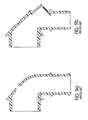
- Figures 8a, 8b , 9a, and 9b show prior art elbows manufactured by ResMed Limited for the STANDARD and MODULAR masks respectively.
- Figures 8c, 8d , 9c, and 9d show related art elbows manufactured by ResMed Limited for the ULTRA MIRAGE ® and MIRAGE ® VISTA masks respectively.
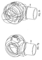
- Figures 11a to 11f show prior art elbows in the WHISPER swivel I and swivel II masks manufactured by Respironics.
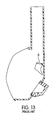
- Figures 12 and 13 show a prior art mask SERENITY mask manufactured by DeVilbiss in which the interior of the nasal cavity includes a baffle B for redirecting incoming gas.
- a mask that includes a cushion with a gusset will have a larger cavity, and hence more dead-space than a mask without a gusset, everything else being equal.
- the mask Since the mask is to be used by sleeping users, it is also desirable to reduce or eliminate noise from all sources, including those caused by the venting of gases from the mask.
- Kwok (PCT/AU98/00067 , published as WO 98/34665 ) describes a mask and a vent.
- the vent comprises a soft flexible insert piece with a series of orifices.
- Drew et al. (PCT/AU00/00636 published as WO 00/78381 ) disclose a connector that comprises a mask end for connecting, in fluid communication, with the interior of a respiratory mask and a supply conduit end disposed at an angle to the mask end for connecting, in fluid communication, with the outlet of a breathable gas supply conduit.
- the connector also includes a gas washout vent passage having an inlet adjacent to, or forming part of, the mask end in fluid communication with the interior of the respiratory mask and an outlet in fluid communication with the atmosphere.
- the outlet includes an interior surface that forms a smooth prolongation with an adjacent exterior surface of the connector.
- the vent outlet is disposed on the side of the connector remote the mask end, has a generally part-annular cross section and is adapted to direct the washout gas in a direction substantially perpendicular to the longitudinal axis of the mask end and substantially parallel to the longitudinal axis of the supply conduit end towards the supply conduit end.
- Moore et al. (co-pending provisional application serial no. 60/502.509, filed August 12, 2002 ) describe a mask system including a swivel elbow with a vent.
- Correa et al. discloses a nasal mask assembly with a miniature nare seal.
- the mask assembly includes a conduit receptor that attaches to a gas delivery tube. Downstream of the conduit receptor is a bore that receives a stem having opposed flanges. The flanges separate the incoming gas into a plurality of channel, such that the gas is provided to one of a plurality of spatial regions in the interior of the nare seal.
- vents and connectors described in the previous preferences provide adequate intake of breathable air/gas and venting for masks that have a small amount of dead-space, e.g., without gussets, they may be inadequate to provide air intake and CO 2 removal in masks that have larger amounts of dead-space, e.g., with gussets. Therefore, there exists a need in the art for a swivel elbow and mask assembly that overcome the problems listed above.
- a first aspect of the invention is directed towards providing an elbow for a mask which provides improved flow patterns for inlet and exhaust flows.
- a second aspect of the invention is directed towards providing an elbow, comprising a baffle.
- a third aspect of the invention is directed towards providing an elbow for a mask that includes an exhaust port for a mask and a baffle that extends from the elbow into the mask cavity.
- Another aspect of the invention is directed towards providing a swivel elbow including an exhaust port for a mask, wherein the swivel elbow includes structure for ensuring that fresh air from the blower does not directly reach the vent.
- Another aspect of the invention is directed towards a swivel elbow assembly that is easy to assemble and disassemble:
- Another aspect of the invention is directed towards a mask assembly using an elbow assembly that is quieter for the user and/or bed partner.
- an elbow assembly for a respiratory mask comprising an elbow, including a portion adapted to engage a gas delivery tube and another portion that is detachable and is coupled to the mask.
- the elbow further defines an inlet port to deliver incoming gas into a nasal breathing cavity defined by the mask and an exhaust port separated from the inlet port by a curved baffle.
- Another aspect of the invention is directed towards providing an elbow for a mask comprising: (i) a portion for connecting to a gas delivery tube; (ii) a portion that is connected to a mask cavity; (iii) an inlet port to deliver incoming gas into the breathing cavity; (iv) an exhaust port to washout CO 2 ; and (v) a baffle that separates the inlet and exhaust ports.
- Another aspect of the invention is directed towards a baffle for use with an elbow and mask assembly, for directing the inlet and outlet flows of the mask assembly.
- a further aspect of the invention is directed towards a mask assembly comprising a mask frame, a mask cushion, and an elbow assembly.
- Figure 1 shows an exploded cross-sectional view of a mask assembly 5 according to one embodiment of the present invention.
- the mask assembly 5 is intended to be worn by a user 1 and substantially surrounds the nose 3 of the user 1.
- the mask assembly 5 includes, for example, a mask frame 10, a swivel elbow assembly 20 connected to the mask frame 10, and a cushion 30 connected to the mask frame 10.
- the swivel elbow assembly is adapted to be connected to an air tube 168 that delivers breathable gas to the user 1.
- the cushion 30 is designed to substantially surround the user's nose 3 and apply pressure around the cushion's 30 perimeter while minimizing and/or avoiding contact with pressure sensitive regions on the user's face. Some parts of the user's face, for example, the nasal bridge region, require special attention to achieve a balance between pressure and seal. It is also desirable to provide a low profile mask to improve the comfort level of the user 1 by improving stability, and to reduce the forces which may tend to pivot the mask assembly 5 relative to the user's face. While the cushion 30 is shown as being used with a nasal mask assembly, it can also be designed for use with a full face mask or a nasal/oro mask assembly.
- the cushion 30 has a face-contacting side 38 and a non face-contacting side 39.
- the non-face contacting side 39 of the cushion 30 engages the mask frame 10 at points 34a and 34b.
- Any type of connection system can be used for connecting the cushion 30 to the mask frame 10 in the mask assembly 5.
- Some examples include interior cushion clips or exterior cushion clips, which are used in ResMed's Ultra Mirage ® mask, which is described in U.S. Patent No. 6,412,487 .
- the cushion 30 can be permanently or detachably and/or reattachably connected to the mask frame 10.
- Other forms of cushion connection may be used such as friction fits, gluing and tongue and groove mechanisms.
- the mask frame 10 includes at least one aperture 42, adapted to fit the elbow assembly 20.
- the aperture 42 has a diameter in its broadest aspect between about 20 mm to about 40 mm, more preferably a diameter between about 25 mm to about 30 mm, and most preferably a diameter of about 28 mm.
- the aperture 42 preferably has a generally circular shape. However, the aperture 42 may have a non-circular shape.
- the mask frame 10 may have a plurality of apertures therethrough with the elbow assembly 20 coupled to the mask frame 10 such that it surrounds the plurality of apertures.
- Figure 2 is a cross-sectional view of the mask assembly 5, showing one embodiment of the mask frame 10, one embodiment of the cushion 30, and one embodiment of the elbow assembly 20, connected together according to one embodiment of the present invention.
- Figure 2 also shows a vent cover 180 attached to the swivel elbow 160.
- the vent cover 180 directs exhaust air along the air tube therefore avoiding disturbance of a bed partner and minimizing noise.
- the aperture 42 may optionally include a ring 400.
- Figure 3a is a perspective view of the ring 400.
- Ring 400 includes an outer ring 310 and an inner ring 307 defining a passage 306 which directs exhaust through the vent cover 180, e.g., via a vent cavity 308.
- the outer ring 310 is attached to the inner ring 307 by at least one connecting arm 304.
- ring 400 has three connecting arms 304. It would be evident to a person skilled in the art that different numbers of connecting arms 304 can be used.
- the ring 400 is fabricated as one piece with the mask frame 10.
- the inner diameter of the aperture 42 is co-incident with the outer ring 310 (i.e., the outer ring 310 is the inner diameter of the aperture 42).
- the ring 400 is fabricated separately and adapted to be detachable engaged with the mask frame 10.
- Each connecting arm 304 can be essentially straight or can include depressions, notches, and/or projections.
- the connecting arm 304 includes one notch 303 and a projection 305.
- the profile of the ring 400 is shown in Figure 3b .
- Figure 3b is a cross-sectional view of the area surrounding the aperture 42 in the mask frame 10.
- the aperture 42 is surrounded by a flange 301 and a lip 300.
- the mask frame 10 in this embodiment also includes a bump 302.
- the flange 301, lip 300, and bump 302 are adapted to engage the elbow assembly 20.
- the outer ring 310 of the ring 400 is integrated with the flange 301. This causes a through channel defined by the aperture 42 in the mask frame 10 and the passage 306 in the ring 400.
- the outer ring 310 has a diameter in its broadest aspect between about 20 mm to about 40 mm, more preferably a diameter between about 25 mm to about 30 mm, and most preferably a diameter about 24 mm.
- the passage 306 has a diameter in its broadest aspect between about 4 mm to about 12 mm, more preferably a diameter between about 6 mm to about 10 mm, and most preferably a diameter about 8 mm.
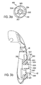
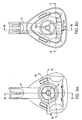
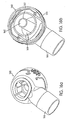
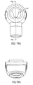
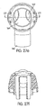
- FIGS 4a and 4b show one embodiment of a swivel elbow 160 in greater detail.
- the swivel elbow 160 is rotationally connected to the mask frame 10 and includes a stem 166 which is adapted to receive the air tube 168 to supply pressurized breathable air or gas from a blower (not shown).
- the stem 166 includes an element 165.
- a top of element 165 is adapted to engage a bottom of the vent cover 180.
- Figure 4a is a cross-sectional view of one embodiment of the swivel elbow 160. It shows that the swivel elbow 160 includes a collar 173 that surrounds the end portion 169 of the elbow 160. The end portion 169 of the elbow 160 extends beyond the collar 173 to improve alignment when assembled into the mask frame 10. In particular, the end portion 169 is adapted to engage notch 303 in the ring 400 (if used). The collar 173 is spaced away from the end portion 169 in concentric relation so as to form a receiving space 183 between the collar 173 and the end portion 169. Collar 173 is adapted to engage bump 302 when the swivel elbow assembly 20 is attached to the mask frame 10.
- a detachable swivel elbow connection is described in U.S. Patent Application No. 60/402,509, filed August 12, 2002 , the contents of which are incorporated in their entirety by reference herein.
- a baffle 161 to separate inlet port 162 from the exhaust port 164 has been developed.
- the exhaust cavity 308 is shown in Fig. 4a as well.
- the exhaust cavity 308 directs gas washout to the vent cover 180, which is not shown in Fig. 4a .
- the depth of the baffle 161 is one design parameter that has been manipulated to improve CO 2 washout.
- a number of different forms of the elbow 160 and the mask frame 10 can be produced to create the desired baffle depth.
- the mask frame 10 does not form the baffle 161, but the whole baffle depth is formed by the elbow 160.
- the ring 400 increases the depth of the baffle 161, which also improves CO 2 washout in mask assemblies 5 with large breathing cavities 35.
- the swivel elbow 160 includes an intake port 162 and an exhaust port 164.
- the exhaust port 164 is separated from the intake port 162 by the baffle 161 provided within the interior portion of the elbow 160, as shown in Figures 4a and 4b .
- the orientation of the intake 162 and exhaust 164 ports is selected such that the incoming gas, indicated by the directional arrow A in the intake port 162, less directly impacts the flow of gas washout indicated by the directional arrow B, along the exhaust port 164. Further, the air/gas entering the elbow 160 is less likely to flow directly into the exhaust port 164 since the baffle 161 forces the incoming air to take a tortuous path, e.g., turn around about 180°, before being able to exit through the exhaust port 164.
- the baffle 161 is generally curved.
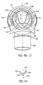
- Figure 4b shows the baffle 161 according to one embodiment of the present invention.
- the baffle 161 is generally sinusoidally-shaped and disposed about a center line 100 in a generally symmetric manner.
- the baffle 161 includes two points 150a and 150b of attachment to the end portion 169, a central portion 152, and a bottom 155.
- the center line 100 intersects the bottom 155 of the baffle 161.
- the baffle 161 has an inner surface 153 and an outer surface 154, shown in greater detail in Figure 4c .
- the baffle 161 includes at least one protrusion 163 that extends from the outer surface 154.
- the baffle 161 is disposed in a manner such that when the elbow assembly 20 is engaged with the mask frame 10, the inner ring 305 of the ring 400 is situated such that the inner surface 153 is in close proximity with the inner ring 305.
- the shape of the baffle 161 has several advantages, some of which are: (i) the incoming gas/air supply in the inlet port 162 is directed by the bottom 155 and/or the protrusion 163, which provides a more even flow to the user 1; (ii) the bottom 155 is generally situated under the user's nostrils such that the exhaust air (rich in CO 2 ) vented out the exhaust port 164 efficiently; and/or (iii) the noise produced by the user 1 is reduced.
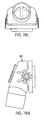
- FIGS 4d and 4e Other embodiments of the baffle 161 are shown in Figures 4d and 4e .
- the baffle 161 does not contain the protrusion 163.
- the baffle 161 is inverted with respect to Figures 4b and 4d .
- the center line 100 is disposed vertically. However, it is within the scope of this invention that additional center lines be disposed horizontally or at any angle between vertical and horizontal.
- baffle 161 may be M-, C-, or V-shaped.
- a further advantage of a baffle 161 in accordance with an embodiment of the invention is that the cross-sectional area of the exhaust flow path increases from a first end in the interior of the mask to a second end, near the exhaust port 164. In this way, the velocity of the air exhausted via the exhaust port 164 is slowed down, or at least not increased, as it flows out of the elbow 160. This contributes to decreasing the noise of the vent. It is also within the scope of the invention for the elbow 160 to be or be devoid of a vent cavity.
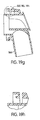
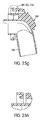
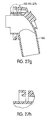
- FIG. 18a to 19j An embodiment of the invention with an M-shaped baffle and increasing vent cavity is shown in Figures 18a to 19j .
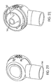
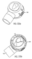
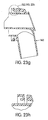
- An embodiment of the invention with a V-shaped baffle and no vent cavity is shown in Figures 22a to 23j .
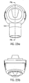
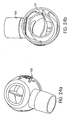
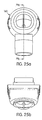
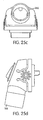
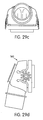
- An embodiment of the invention with a C-shaped baffle and increasing vent cavity is shown in Figures 24a to 25j .
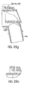
- An embodiment of the invention with a V-shaped baffle and increasing vent cavity is shown in Figures 28a to 29j .
- All the baffle shapes described provide noise reduction, increased CO 2 washout, and/or optimized and/or low flow impedance. Additional baffle 161 shapes and orientations are possible and within the scope of the present invention.
- the baffle 161 defines an inlet port 162, through which air from a blower can enter, and an exhaust port 164 within the elbow 160. Air from the blower passes through the air tube 168 to the elbow 160, where it passes through the inlet port 161 and is "injected” into the cavity 35 of the mask 10. Air continually flows from the mask cavity 35 out to atmosphere via the ring 400 to the exhaust port 164 of the elbow 160.
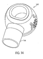
- FIGS 14a to 15j While the embodiment shown in Figures 14a to 15j does not include a baffle 161, it does incorporate other advantages of the invention, including its low profile.
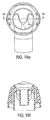
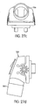
- FIGs 30a-30d show a swivel elbow in accordance with an alternative embodiment of the invention similar to the embodiment shown in Figures 26a, 26b , 27a-27j .
- this embodiment there are two "C"-shaped baffles 161 ( Figure 30c ). Air enters the elbow from a blower via a stem 166 and is directed to turn through approximately 90 degrees and passes into the mask cavity via the intake port 162 which is located in the center of the elbow. ( Figures 30b and 30d ). Air from the mask cavity passes out through the exhaust ports 164 which are located on the sides of the elbow and into vent cavity 308 ( Figures 30a and 30d ).
- the exhaust port 164 In order to provide sufficient exhaust flow, it is desirable that the exhaust port 164 have a low flow impedance.
- One way to achieve this is to have as large a cross-sectional area for the exhaust port 164 as possible.
- increasing the cross-sectional area of the exhaust port 164 comes at the expense of the inlet port 162.
- the baffle 161 of the elbow 160 extends into the mask frame 10 and is molded in one piece.
- the baffle 161 is split between the swivel elbow 160 and the mask frame 10, and the combination of the two provides a baffle 161 of sufficient length.
- the swivel elbow 160 is suitable for use with shallow mask frames 10 that do not require a long overall baffle 161.
- the baffle 161 is partly formed by the elbow 160 and partly by the frame 10. This configuration can be created in different forms or baffle shapes.
- the baffle 161 is formed from the combination of elbow 160 and frame 10, it is possible to create a modular elbow design which can be used with a variety of different mask systems.
- a circular ring 400 is added to the frame.
- the ring 400 extends the depth of a baffle 161 into the cavity 35 of the mask frame 10. In this way, the likelihood that fresh inlet air short circuits the mask cavity 35 is reduced. An end of the ring is close to the edge of the user's nose and hence this configuration assists to direct exhaled air from the nose towards the exhaust port 164.
- the use of a ring 400 molded into the frame 10 obviates the need to extend the baffle 161 of the swivel elbow 160 into the mask frame 10. While a long baffled elbow is suitable for mask assemblies with large cavities, it may not be suitable for mask assemblies with shallow cavities, since it may interfere with a patient's nose. Hence by the use of the combination of mask frame 10 with ring 400 and an elbow 160 with a short baffle, the same elbow 160 can be used on both shallow and large cavitied mask assemblies.
- the baffle 161 is formed within a cylindrical portion of the elbow 160 adapted for connection to the frame.
- the baffle 161 defines a centrally located exhaust port 164. Air from the blower passes around the outside of the exhaust port 164.
- the construction of the elbow 160 in combination with the angle between the two generally cylindrical portions of the elbow 160 leads to a potential dead spot within the blower airflow path.
- Potential dead spots within the blower flow path represent an opportunity for an exhaust flow path.
- the exhaust flow path is positioned within the elbow 160 in what would otherwise be a dead spot for blower flow.
- the cross-sectional area of the exhaust flow path can be increased without having a significant impact on the impedance of the blower flow path and/or an adverse effect on the undesirable noise that may be produced during washout.
- baffle 161 in accordance with the invention does not present a significant flow impedance for the blower flow. While a variety of different baffle designs are possible, those which impede the flow path create a resistance to flow from the blower, causing a large pressure drop along the elbow 160 than would otherwise be the case. The larger the pressure drop in the elbow, the harder the blower must work in order to provide air at a given positive pressure. The harder the blower must work, the more noise is created by the blower, which makes it more difficult for a patient to sleep.
- the elbow 160 comprises two cylindrical portions, a first portion adapted for connection to an air delivery tube 168 and having a first axis; and a second portion adapted for connection to the mask frame 10 and having a second axis, wherein the two axes are disposed at an interior angle of about 100 degrees.
- a further advantage of a swivel elbow 160 in accordance with the invention is that it has a low height (the perpendicular distance it extends from the frame). This reduces the visual impact of the swivel elbow 160, reduces the bending moment of the swivel elbow 160 and reduces the "lever arm” effect of the swivel elbow 160.
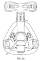
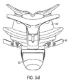
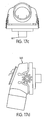
- Figures 5a to 5d show various views of the respiratory mask assembly 10 according to one embodiment of the present invention.
- Figure 6a to 6m show several views of the respiratory mask assembly 10.
- Figures 7a to 7i show several views of the swivel elbow 160.
- the dimensions shown in Figures 5a to 7i are preferred illustrative embodiments that may be varied up to ⁇ 20%, and preferably ⁇ 10%, in embodiments.
- a swivel elbow and mask frame 10 in accordance with a preferred embodiment of the invention include providing: (i) sufficient inlet area and optimized shape such that flow into the mask assembly 5 is not impeded; and (ii) sufficient outlet flow area that has, in addition, a smooth profile and no restrictions other than a final smooth tapered exit to provide a quiet vent.
- the latter advantage has been difficult to achieve prior to the present invention.
Landscapes
- Health & Medical Sciences (AREA)
- General Health & Medical Sciences (AREA)
- Pulmonology (AREA)
- Heart & Thoracic Surgery (AREA)
- Life Sciences & Earth Sciences (AREA)
- Biomedical Technology (AREA)
- Anesthesiology (AREA)
- Hematology (AREA)
- Engineering & Computer Science (AREA)
- Animal Behavior & Ethology (AREA)
- Public Health (AREA)
- Veterinary Medicine (AREA)
- Emergency Medicine (AREA)
- Business, Economics & Management (AREA)
- Emergency Management (AREA)
- Respiratory Apparatuses And Protective Means (AREA)
Description
- The present application claims priority to
U.S. Provisional Application Serial No. 60/424,695 filed November 8, 2002 U.S. Provisional Application Serial No. 60/474,928 filed June 3, 2003 U.S. Non-Provisional Application Serial No. 10/235,846 filed September 6, 2002 U.S. Provisional Application No. 60/317,486 filed September 7, 2001 U.S. Provisional Application Serial No. 60/342,854 filed December 28, 2001 - The invention relates to a mask frame and elbow for use with a mask system for Non-invasive Positive Pressure Ventilation (NPPV) and for continuous positive airway pressure (CPAP) therapy of sleep disordered breathing (SDB) conditions such as obstructive sleep apnea (OSA).
- The use of NPPV for treatment of SDB, such as OSA was pioneered by Sullivan (see, for example,
U.S. Pat. No. 4,944,310 ). Apparatus for this treatment involves a blower which delivers a supply of air at positive pressure to a patient interface via an air delivery conduit. The patient interface may take several forms such as nasal masks and nose and mouth masks. Patients must wear a mask all night while sleeping to receive the therapy. - Masks typically comprise a rigid shell or frame and a soft face-contacting cushion that spaces the frame away from the face and forms a seal with the patient's face. The frame and cushion define a cavity which receives the nose, or nose and mouth. The mask is held in position by headgear, which usually comprises an arrangement of straps that passes along the side of the face to the back or crown of the head.
-
Kwok et al. (U.S. Pat. No. 6,112,746 ) describe a nasal mask and mask cushion. The mask cushion is a substantially triangularly shaped frame from which extends a membrane. The mask frame has a scalloped edge by which the mask cushion is affixed to a mask frame. The membrane has an aperture into which the user's nose is received. The membrane is spaced away from the rim of the frame, and its outer surface has substantially the same shape as the rim. -
Frater et al. (PCT Patent Application AU01/00746 WO 01/97893 - During the course of the respiratory cycle patients inhale air, largely comprising a mixture of nitrogen and oxygen, and exhale a mixture of gases including a relatively higher fraction of CO2. In a nasal mask system where the patient breathes through the nose, there can be a build-up of CO2 in the mask cavity which can lead to undesirable CO2 re-breathing. Hence a variety of vents have been developed for use with masks. The amount of CO2 in the mask cavity is a function of vent geometry, mask geometry, flow patterns within the mask and the amount of dead-space within the mask cavity.
- The mask is typically joined to the air delivery conduit using a friction fit. Since the blower is typically placed beside a patient's bed, it is typical that the air delivery conduit be at least 1 meter long. Occasionally, movement of the air delivery conduit can disrupt the seal. Furthermore, some patients prefer to have the conduit in one position (for example passing over their heads), whereas other patients prefer to have it in another position (for example to the left or right side). Hence swivel elbows were developed for some masks.
- Swivel elbows typically include: (i) a cylindrical first portion, having an axis aligned in a first direction and being adapted for connection to an air delivery conduit; and (ii) a cylindrical second portion, having an axis aligned in a second direction and being adapted for connection to a frame of a mask.
- The first and second directions typically are at right angles to one another. The first portion has an outer diameter slightly smaller than the inner diameter of typical air delivery conduit tubing, so that the tubing can overfit the first portion and be held in position by friction. A free end of the second portion is adapted to pass through an orifice in the mask frame. Such known swivel elbows typically include a vent. While some vents are simply holes, such as those in the Puritan-Bennett SOFTFIT mask (
Figure 10a ), others are more sophisticated, such as those used with the ResMed ULTRA MIRAGE® mask. - A problem with the prior art swivel elbows incorporating a simple vent, such as the Puritan-Bennett SOFTFIT (
Figure 10a ), the Respironics CONTOUR-DELUXE (Figure 10c ) and the related art Tiara ADVANTAGE elbows (Figure 10b ), is that air from the blower can simply short-circuit the mask and pass straight out of the vent. This is a particular problem when a patient is being given supplemental oxygen, which is expensive. A significant portion of the oxygen being fed to the elbow simply passes out the vent without entering the mask. -
Figures 8a, 8b ,9a, and 9b show prior art elbows manufactured by ResMed Limited for the STANDARD and MODULAR masks respectively.Figures 8c, 8d ,9c, and 9d show related art elbows manufactured by ResMed Limited for the ULTRA MIRAGE® and MIRAGE® VISTA masks respectively.Figures 11a to 11f show prior art elbows in the WHISPER swivel I and swivel II masks manufactured by Respironics.Figures 12 and13 show a prior art mask SERENITY mask manufactured by DeVilbiss in which the interior of the nasal cavity includes a baffle B for redirecting incoming gas. - A mask that includes a cushion with a gusset will have a larger cavity, and hence more dead-space than a mask without a gusset, everything else being equal. Hence in a mask assembly with a gusset, particular attention needs to be paid to venting the mask to ensure that sufficient CO2 is washed out by a continuous influx of fresh air.
- Since the mask is to be used by sleeping users, it is also desirable to reduce or eliminate noise from all sources, including those caused by the venting of gases from the mask.
-
Kwok (PCT/AU98/00067 WO 98/34665 -
Drew et al. (PCT/AU00/00636 WO 00/78381 - Moore et al. (co-pending provisional application serial no.
60/502.509, filed August 12, 2002 -
Correa et al. (U.S. Pat. No. 6,119,694 ) discloses a nasal mask assembly with a miniature nare seal. The mask assembly includes a conduit receptor that attaches to a gas delivery tube. Downstream of the conduit receptor is a bore that receives a stem having opposed flanges. The flanges separate the incoming gas into a plurality of channel, such that the gas is provided to one of a plurality of spatial regions in the interior of the nare seal. - Further connectors and supply conduits for respiratory masks having a gas washout vent passage are disclosed in
WO 00/78381 A1 - While the vents and connectors described in the previous preferences provide adequate intake of breathable air/gas and venting for masks that have a small amount of dead-space, e.g., without gussets, they may be inadequate to provide air intake and CO2 removal in masks that have larger amounts of dead-space, e.g., with gussets. Therefore, there exists a need in the art for a swivel elbow and mask assembly that overcome the problems listed above.
- A first aspect of the invention is directed towards providing an elbow for a mask which provides improved flow patterns for inlet and exhaust flows.
- A second aspect of the invention is directed towards providing an elbow, comprising a baffle.
- A third aspect of the invention is directed towards providing an elbow for a mask that includes an exhaust port for a mask and a baffle that extends from the elbow into the mask cavity.
- Another aspect of the invention is directed towards providing a swivel elbow including an exhaust port for a mask, wherein the swivel elbow includes structure for ensuring that fresh air from the blower does not directly reach the vent.
- Another aspect of the invention is directed towards a swivel elbow assembly that is easy to assemble and disassemble:
- Another aspect of the invention is directed towards a mask assembly using an elbow assembly that permits better intake of breathable air and/or better removal of exhaust air.
- Another aspect of the invention is directed towards a mask assembly using an elbow assembly that is quieter for the user and/or bed partner.
- Another aspect of the invention is directed towards an elbow assembly for a respiratory mask comprising an elbow, including a portion adapted to engage a gas delivery tube and another portion that is detachable and is coupled to the mask. The elbow further defines an inlet port to deliver incoming gas into a nasal breathing cavity defined by the mask and an exhaust port separated from the inlet port by a curved baffle.
- Another aspect of the invention is directed towards providing an elbow for a mask comprising: (i) a portion for connecting to a gas delivery tube; (ii) a portion that is connected to a mask cavity; (iii) an inlet port to deliver incoming gas into the breathing cavity; (iv) an exhaust port to washout CO2; and (v) a baffle that separates the inlet and exhaust ports.
- Another aspect of the invention is directed towards a baffle for use with an elbow and mask assembly, for directing the inlet and outlet flows of the mask assembly.
- A further aspect of the invention is directed towards a mask assembly comprising a mask frame, a mask cushion, and an elbow assembly.
- Other aspects, features and advantages of this invention will become apparent from the following detailed description when taken in conjunction with the accompanying drawings, which are a part of this disclosure and which illustrate, by way of example, principles of this invention.
-
-
Figure 1 is an exploded cross-sectional view of a respiratory mask assembly according to one embodiment of the present invention; -
Figure 2 is an assembled cross-sectional view of the respiratory mask assembly shown inFigure 1 ; -
Figure 3 a is a perspective view of a ring according to one embodiment of the present invention; -
Figure 3b is a cross-sectional view of a frame portion of the respiratory mask assembly shown inFigure 2 ; -
Figure 4a is a cross-sectional view of one embodiment of the swivel elbow according to the present invention; -
Figure 4b is a front view of the swivel elbow shown inFigure 4a ; -
Figure 4c is a detailed cross-sectional view of the lower portion of the baffle shown in the swivel elbow ofFigure 4b ; -
Figure 4d is a perspective view of a swivel elbow according to another embodiment of the present invention; -
Figure 4e is a perspective view of a swivel elbow according to another embodiment of the present invention; -
Figure 5a is a front view of the respiratory mask assembly shown inFigure 2 ; -
Figure 5b is a left side view of the respiratory mask assembly shown inFigure 5a ; -
Figure 5c is a right side view of the respiratory mask assembly shown inFigure 5a ; -
Figure 5d is a top view of the respiratory mask assembly shown inFigure 5a ; -
Figure 6a is a front view of the respiratory mask frame shown inFigure 5a ; -
Figure 6b is a rear view of the respiratory mask frame shown inFigure 6a ; -
Figure 6c is a front perspective view of the respiratory mask frame shown inFigure 6a ; -
Figure 6d is a rear perspective view of the respiratory mask frame shown inFigure 6a ; -
Figure 6e is a cross-sectional view alongline 6e-6e of the respiratory mask frame shown inFigure 6a ; -
Figure 6f is a right side view of the respiratory mask frame shown inFigure 6a ; -
Figure 6g is a cross-sectional view alongline 6g-6g of the respiratory mask frame shown inFigure 6b ; -
Figure 6h is a cross-sectional view alongline 6h-6h of the respiratory mask frame shown inFigure 6a ; -
Figure 6i is a cross-sectional view alongline 6i-6i of the respiratory mask frame shown inFigure 6b ; -
Figure 6j is a cross-sectional view alongline 6j-6j of the respiratory mask frame shown inFigure 6g ; -
Figure 6k is a cross-sectional view alongline 6k-6k of the respiratory mask frame shown inFigure 6a ; -
Figure 6I is a bottom view of the respiratory mask frame shown inFigure 6b ; -
Figure 6m is a detailed cross-sectional view of an exhaust port according to the embodiment of the respiratory mask frame shown inFigure 6g ; -
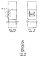
Figure 7a is a front view of the front of the swivel elbow shown inFigure 4a ; -
Figure 7b is an alternative front view of the swivel elbow shown inFigure 7a ; -
Figure 7c is a cross-sectional view alongline 7c-7c of the swivel elbow shown inFigure 7a ; -
Figure 7d is a right side view of the swivel elbow shown inFigure 7a ; -
Figure 7e is a top view of the top of the swivel elbow shown inFigure 7a ; -
Figure 7f a cross-sectional view alongline 7f-7f of the swivel elbow shown inFigure 7b ; -
Figure 7g is a rear perspective view of the swivel elbow shown inFigure 7a ; -
Figure 7h is a front perspective view of the swivel elbow shown inFigure 7a ; -
Figure 7i is a bottom view of the swivel elbow shown inFigure 7a ; -
Figure 8a is a rear view of a prior art swivel elbow; -
Figure 8b is a rear view of a prior art swivel elbow; -
Figure 8c is a rear view of a related art swivel elbow; -
Figure 8d is a rear view of a related art swivel elbow; -
Figure 9a is a cross-sectional view of the front of the swivel elbow shown inFigure 8a ; -
Figure 9b is a cross-sectional view of the front of the swivel elbow shown inFigure 8b ; -
Figure 9c is a cross-sectional view of the front of the swivel elbow shown inFigure 8c ; -
Figure 9d is a cross-sectional view of the front of the swivel elbow shown inFigure 8d ; -
Figure 10a is a cross-sectional view of a prior art swivel elbow; -
Figure 10b is a cross-sectional view of a related art swivel elbow; -
Figure 10c is a cross-sectional view of a prior art swivel elbow; -
Figure 11a is a front view of a side of a part of a prior art swivel elbow; -
Figure 11b is a left side view of the swivel elbow shown inFigure 11a ; -
Figure 11c is a detailed cross-sectional view of vents on the swivel elbow shown inFigure 11a ; -
Figure 11d is an exploded view of a part of another prior art swivel elbow; -
Figure 11e is a cross-sectional view of the swivel elbow shown inFigure 11 d in an assembled state; -
Figure 11f is a bottom view of the swivel elbow shown inFigure 11e ; -
Figure 12 is a rear view of a prior art respiratory mask assembly; -
Figure 13 is a cross-sectional view along line 13-13 of the respiratory mask assembly shown inFigure 12 ; -
Figure 14 is a front perspective view of a swivel elbow according to another embodiment of the invention; -
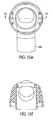
Figure 15a is a front view of the swivel elbow shown inFigure 14 ; -
Figure 15b is a top view of the swivel elbow shown inFigure 15a ; -
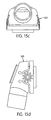
Figure 15c is a bottom view of the swivel elbow shown inFigure 15a ; -
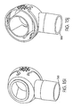
Figure 15d is a right side view of the swivel elbow shown inFigure 15a ; -
Figure 15e is a right side view of the swivel elbow shown inFigure 15d ; -
Figure 15f is a cross-sectional view alongline 15f-15f of the swivel elbow shown inFigure 15e ; -
Figure 15g is a cross-sectional view alongline 15g-15g of the swivel elbow shown inFigure 15a ; -
Figure 15h is a detailed view of a portion of the swivel elbow shown inFigure 15g ; -
Figure 15i is a front perspective view of the swivel elbow shown inFigure 15a ; -
Figure 15j is a rear perspective view of the swivel elbow shown inFigure 15a ; -
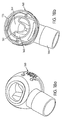
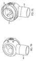
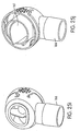
Figure 16a is a front perspective view of a swivel elbow according to another embodiment of the invention; -
Figure 16b is a rear perspective view of the swivel elbow shown inFigure 16a ; -
Figure 17a is a front view of the swivel elbow shown inFigure 16a ; -
Figure 17b is a top view of the swivel elbow shown inFigure 17a ; -
Figure 17c is a bottom view of the swivel elbow shown inFigure 17a ; -
Figure 17d is a right side view of the swivel elbow shown inFigure 17a ; -
Figure 17e is a rear view of the swivel elbow shown inFigure 17a ; -
Figure 17f is a cross-sectional view alongline 17fFigure 17e ; -
Figure 17g is a cross-sectional view alongline 17g-17g of the swivel elbow shown inFigure 17a ; -
Figure 17h is a detailed view of a portion of the swivel elbow shown inFigure 17g ; -
Figure 17i is another front perspective view of the swivel elbow shown inFigure 16a at a slightly different angle; -
Figure 17j is a rear perspective view of the swivel elbow shown inFigure 16b at a slightly different angle; -
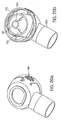
Figure 18a is a front perspective view of a swivel elbow according to another embodiment of the invention; -
Figure 18b is a rear perspective view of the swivel elbow shown inFigure 18a ; -
Figure 19a is a front view of the swivel elbow shown inFigure 18a ; -
Figure 19b is a top view of the swivel elbow shown inFigure 19a ; -
Figure 19c is a bottom view of the swivel elbow shown inFigure 19a ; -
Figure 19d is a right side view of the swivel elbow shown inFigure 19a ; -
Figure 19e is a rear view of the swivel elbow shown inFigure 19a ; -
Figure 19f is a cross-sectional view alongline 19fFigure 19e ; -
Figure 19g is a cross-sectional view alongline 19g-19g of the swivel elbow shown inFigure 19a ; -
Figure 19h is a detailed view of a portion of the swivel elbow shown inFigure 19g ; -
Figure 19i is another front perspective view of the swivel elbow shown inFigure 18a at a slightly different angle; -
Figure 19j is another rear perspective view of the swivel elbow shown inFigure 18b at a slightly different angle; -
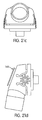
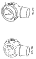
Figure 20a is a front perspective view of a swivel elbow according to another embodiment of the invention; -
Figure 20b is a rear perspective view of the swivel elbow shown inFigure 20a ; -
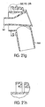
Figure 21a is a front view of the swivel elbow shown inFigure 20a ; -
Figure 21b is a top view of the swivel elbow shown inFigure 21a ; -
Figure 21 c is a bottom view of the swivel elbow shown inFigure 21 a; -
Figure 21d is a right side view of the swivel elbow shown inFigure 21a ; -
Figure 21 e is a rear view of the swivel elbow shown inFigure 21 a; -
Figure 21f is a cross-sectional view alongline 21fFigure 2 1 e; -
Figure 21 g is a cross-sectional view alongline 21g-21g of the swivel elbow shown inFigure 21 a; -
Figure 21h is a detailed view of a portion of the swivel elbow shown inFigure 2 1 g; -
Figure 21i is another front perspective view of the swivel elbow shown inFigure 20a at a slightly different angle; -
Figure 21j is another rear perspective view of the swivel elbow shown inFigure 20b at a slightly different angle; -
Figure 22a is a front perspective view of a swivel elbow according to another embodiment of the invention; -
Figure 22b is a rear perspective view of the swivel elbow shown inFigure 22a ; -
Figure 23a is a front view of the swivel elbow shown inFigure 22a ; -
Figure 23b is a top view of the swivel elbow shown inFigure 23a ; -
Figure 23c is a bottom view of the swivel elbow shown inFigure 23a ; -
Figure 23d is a right side view of the swivel elbow shown inFigure 23a ; -
Figure 23e is a rear view of the swivel elbow shown inFigure 23a ; -
Figure 23f is a cross-sectional view alongline 23fFigure 23e ; -
Figure 23g is a cross-sectional view alongline 23g-23g of the swivel elbow shown inFigure 23a ; -
Figure 23h is a detailed view of a portion of the swivel elbow shown inFigure 23g ; -
Figure 23i is another front perspective view of the swivel elbow shown inFigure 22a at a slightly different angle; -
Figure 23j is another rear perspective view of the swivel elbow shown inFigure 22b at a slightly different angle; -
Figure 24a is a front perspective view of a swivel elbow according to another embodiment of the invention; -
Figure 24b is a rear perspective view of the swivel elbow shown inFigure 24a ; -
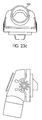
Figure 25a is a front view of the swivel elbow shown inFigure 24a ; -
Figure 25b is a top view of the swivel elbow shown inFigure 25a ; -
Figure 25c is a bottom view of the swivel elbow shown inFigure 25a ; -
Figure 25d is a right side view of the swivel elbow shown inFigure 25a ; -
Figure 25e is a rear view of the swivel elbow shown inFigure 25a ; -
Figure 25f is a cross-sectional view alongline 25fFigure 25e ; -
Figure 25g is a cross-sectional view alongline 25g-25g of the swivel elbow shown inFigure 25a ; -
Figure 25h is a detailed view of a portion of the swivel elbow shown inFigure 25g ; -
Figure 25i is another front perspective view of the swivel elbow shown inFigure 24a at a slightly different angle; -
Figure 25j is another rear perspective view of the swivel elbow shown inFigure 24b at a slightly different angle; -
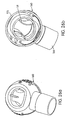
Figure 26a is a front perspective view of a swivel elbow according to another embodiment of the invention; -
Figure 26b is a rear perspective view of the swivel elbow shown inFigure 26a ; -
Figure 27a is a front view of the swivel elbow shown inFigure 26a ; -
Figure 27b is a top view of the swivel elbow shown inFigure 27a ; -
Figure 27c is a bottom view of the swivel elbow shown inFigure 27a ; -
Figure 27d is a right side view of the swivel elbow shown inFigure 27a ; -
Figure 27e is a rear view of the swivel elbow shown inFigure 27a ; -
Figure 27f is a cross-sectional view alongline 27fFigure 27e ; -
Figure 27g is a cross-sectional view alongline 27g-27g of the swivel elbow shown inFigure 27a ; -
Figure 27h is a detailed view of a portion of the swivel elbow shown inFigure 27g ; -
Figure 27i is another front perspective view of the swivel elbow shown inFigure 26a at a slightly different angle; -
Figure 27j is another rear perspective view of the swivel elbow shown inFigure 26b at a slightly different angle; -
Figure 28a is a front perspective view of a swivel elbow according to another embodiment of the invention; -
Figure 28b is a rear perspective view of the swivel elbow shown inFigure 28a ; -
Figure 29a is a front view of the swivel elbow shown inFigure 28a ; -
Figure 29b is a top view of the swivel elbow shown inFigure 29a ; -
Figure 29c is a bottom view of the swivel elbow shown inFigure 29a ; -
Figure 29d is a right side view of the swivel elbow shown inFigure 29a ; -
Figure 29e is a rear view of the swivel elbow shown inFigure 29a ; -
Figure 29f is a cross-sectional view alongline 29fFigure 29e ; -
Figure 29g is a cross-sectional view alongline 29g-29g of the swivel elbow shown inFigure 29a ; -
Figure 29h is a detailed view of a portion of the swivel elbow shown inFigure 29g ; -
Figure 29i is another front perspective view of the swivel elbow shown inFigure 28a at a slightly different angle; -
Figure 29j is another rear perspective view of the swivel elbow shown inFigure 28b at a slightly different angle; -
Figure 30a is a side view of a swivel elbow according to another embodiment of the invention; -
Figure 30b is a right side view of the swivel elbow shown inFigure 30a ; -
Figure 30c is a top view of the swivel elbow shown inFigure 30a ; and -
Figure 30d is a partial bottom view of the swivel elbow shown inFigure 30a . -
Figure 1 shows an exploded cross-sectional view of amask assembly 5 according to one embodiment of the present invention. Themask assembly 5 is intended to be worn by auser 1 and substantially surrounds thenose 3 of theuser 1. Themask assembly 5 includes, for example, amask frame 10, aswivel elbow assembly 20 connected to themask frame 10, and acushion 30 connected to themask frame 10. The swivel elbow assembly is adapted to be connected to anair tube 168 that delivers breathable gas to theuser 1. - The
cushion 30 is designed to substantially surround the user'snose 3 and apply pressure around the cushion's 30 perimeter while minimizing and/or avoiding contact with pressure sensitive regions on the user's face. Some parts of the user's face, for example, the nasal bridge region, require special attention to achieve a balance between pressure and seal. It is also desirable to provide a low profile mask to improve the comfort level of theuser 1 by improving stability, and to reduce the forces which may tend to pivot themask assembly 5 relative to the user's face. While thecushion 30 is shown as being used with a nasal mask assembly, it can also be designed for use with a full face mask or a nasal/oro mask assembly. - The
cushion 30 has a face-contactingside 38 and a non face-contactingside 39. Thenon-face contacting side 39 of thecushion 30 engages themask frame 10 atpoints cushion 30 to themask frame 10 in themask assembly 5. Some examples include interior cushion clips or exterior cushion clips, which are used in ResMed's Ultra Mirage® mask, which is described inU.S. Patent No. 6,412,487 . Thecushion 30 can be permanently or detachably and/or reattachably connected to themask frame 10. Other forms of cushion connection may be used such as friction fits, gluing and tongue and groove mechanisms. - The
mask frame 10 includes at least oneaperture 42, adapted to fit theelbow assembly 20. Theaperture 42 has a diameter in its broadest aspect between about 20 mm to about 40 mm, more preferably a diameter between about 25 mm to about 30 mm, and most preferably a diameter of about 28 mm. Theaperture 42 preferably has a generally circular shape. However, theaperture 42 may have a non-circular shape. Further, themask frame 10 may have a plurality of apertures therethrough with theelbow assembly 20 coupled to themask frame 10 such that it surrounds the plurality of apertures. -
Figure 2 is a cross-sectional view of themask assembly 5, showing one embodiment of themask frame 10, one embodiment of thecushion 30, and one embodiment of theelbow assembly 20, connected together according to one embodiment of the present invention.Figure 2 also shows avent cover 180 attached to theswivel elbow 160. Thevent cover 180 directs exhaust air along the air tube therefore avoiding disturbance of a bed partner and minimizing noise. - The
aperture 42 may optionally include aring 400.Figure 3a is a perspective view of thering 400.Ring 400 includes anouter ring 310 and aninner ring 307 defining apassage 306 which directs exhaust through thevent cover 180, e.g., via avent cavity 308. Theouter ring 310 is attached to theinner ring 307 by at least one connectingarm 304. In the embodiment show inFigure 3a ,ring 400 has three connectingarms 304. It would be evident to a person skilled in the art that different numbers of connectingarms 304 can be used. - In one embodiment, the
ring 400 is fabricated as one piece with themask frame 10. In this embodiment, the inner diameter of theaperture 42 is co-incident with the outer ring 310 (i.e., theouter ring 310 is the inner diameter of the aperture 42). In another embodiment, thering 400 is fabricated separately and adapted to be detachable engaged with themask frame 10. - Each connecting
arm 304 can be essentially straight or can include depressions, notches, and/or projections. In the embodiment shown inFigure 3a , the connectingarm 304 includes onenotch 303 and aprojection 305. The profile of thering 400 is shown inFigure 3b . -
Figure 3b is a cross-sectional view of the area surrounding theaperture 42 in themask frame 10. Theaperture 42 is surrounded by aflange 301 and alip 300. Themask frame 10 in this embodiment also includes abump 302. Theflange 301,lip 300, and bump 302 are adapted to engage theelbow assembly 20. - In the embodiment shown in
Figure 3b , theouter ring 310 of thering 400 is integrated with theflange 301. This causes a through channel defined by theaperture 42 in themask frame 10 and thepassage 306 in thering 400. Theouter ring 310 has a diameter in its broadest aspect between about 20 mm to about 40 mm, more preferably a diameter between about 25 mm to about 30 mm, and most preferably a diameter about 24 mm. Thepassage 306 has a diameter in its broadest aspect between about 4 mm to about 12 mm, more preferably a diameter between about 6 mm to about 10 mm, and most preferably a diameter about 8 mm. -
Figures 4a and4b show one embodiment of aswivel elbow 160 in greater detail. Theswivel elbow 160 is rotationally connected to themask frame 10 and includes astem 166 which is adapted to receive theair tube 168 to supply pressurized breathable air or gas from a blower (not shown). In the embodiment shown, thestem 166 includes anelement 165. A top ofelement 165 is adapted to engage a bottom of thevent cover 180. -
Figure 4a is a cross-sectional view of one embodiment of theswivel elbow 160. It shows that theswivel elbow 160 includes acollar 173 that surrounds theend portion 169 of theelbow 160. Theend portion 169 of theelbow 160 extends beyond thecollar 173 to improve alignment when assembled into themask frame 10. In particular, theend portion 169 is adapted to engagenotch 303 in the ring 400 (if used). Thecollar 173 is spaced away from theend portion 169 in concentric relation so as to form a receivingspace 183 between thecollar 173 and theend portion 169.Collar 173 is adapted to engagebump 302 when theswivel elbow assembly 20 is attached to themask frame 10. One example of a detachable swivel elbow connection is described inU.S. Patent Application No. 60/402,509, filed August 12, 2002 - In order to improve CO2 washout in a
mask assembly 5, especially with a large breathing cavity 35 such as a full-face mask or a cushion with gusset, abaffle 161 toseparate inlet port 162 from theexhaust port 164 has been developed. Theexhaust cavity 308 is shown inFig. 4a as well. Theexhaust cavity 308 directs gas washout to thevent cover 180, which is not shown inFig. 4a . The depth of thebaffle 161 is one design parameter that has been manipulated to improve CO2 washout. A number of different forms of theelbow 160 and themask frame 10 can be produced to create the desired baffle depth. In one embodiment of the invention, themask frame 10 does not form thebaffle 161, but the whole baffle depth is formed by theelbow 160. In another embodiment, thering 400 increases the depth of thebaffle 161, which also improves CO2 washout inmask assemblies 5 with large breathing cavities 35. - The
swivel elbow 160 includes anintake port 162 and anexhaust port 164. Theexhaust port 164 is separated from theintake port 162 by thebaffle 161 provided within the interior portion of theelbow 160, as shown inFigures 4a and4b . The orientation of theintake 162 andexhaust 164 ports is selected such that the incoming gas, indicated by the directional arrow A in theintake port 162, less directly impacts the flow of gas washout indicated by the directional arrow B, along theexhaust port 164. Further, the air/gas entering theelbow 160 is less likely to flow directly into theexhaust port 164 since thebaffle 161 forces the incoming air to take a tortuous path, e.g., turn around about 180°, before being able to exit through theexhaust port 164. - The
baffle 161 is generally curved.Figure 4b shows thebaffle 161 according to one embodiment of the present invention. Thebaffle 161 is generally sinusoidally-shaped and disposed about acenter line 100 in a generally symmetric manner. Thebaffle 161 includes twopoints end portion 169, acentral portion 152, and a bottom 155. Thecenter line 100 intersects the bottom 155 of thebaffle 161. Thebaffle 161 has aninner surface 153 and anouter surface 154, shown in greater detail inFigure 4c . - The
baffle 161 includes at least oneprotrusion 163 that extends from theouter surface 154. Thebaffle 161 is disposed in a manner such that when theelbow assembly 20 is engaged with themask frame 10, theinner ring 305 of thering 400 is situated such that theinner surface 153 is in close proximity with theinner ring 305. - The shape of the
baffle 161 has several advantages, some of which are: (i) the incoming gas/air supply in theinlet port 162 is directed by the bottom 155 and/or theprotrusion 163, which provides a more even flow to theuser 1; (ii) the bottom 155 is generally situated under the user's nostrils such that the exhaust air (rich in CO2) vented out theexhaust port 164 efficiently; and/or (iii) the noise produced by theuser 1 is reduced. - Other embodiments of the
baffle 161 are shown inFigures 4d and 4e . In the embodiment shown inFigure 4d , thebaffle 161 does not contain theprotrusion 163. In the embodiment shown inFigure 4e , thebaffle 161 is inverted with respect toFigures 4b and4d . In the embodiments shown inFigures 4b ,4d, and 4e , thecenter line 100 is disposed vertically. However, it is within the scope of this invention that additional center lines be disposed horizontally or at any angle between vertical and horizontal. - A variety of other baffle shapes are possible. For example, the
baffle 161 may be M-, C-, or V-shaped. A further advantage of abaffle 161 in accordance with an embodiment of the invention is that the cross-sectional area of the exhaust flow path increases from a first end in the interior of the mask to a second end, near theexhaust port 164. In this way, the velocity of the air exhausted via theexhaust port 164 is slowed down, or at least not increased, as it flows out of theelbow 160. This contributes to decreasing the noise of the vent. It is also within the scope of the invention for theelbow 160 to be or be devoid of a vent cavity. - An embodiment of the invention with an M-shaped baffle and increasing vent cavity is shown in
Figures 18a to 19j . An embodiment of the invention with a V-shaped baffle and no vent cavity is shown inFigures 22a to 23j . An embodiment of the invention with a C-shaped baffle and increasing vent cavity is shown inFigures 24a to 25j . An embodiment of the invention with a V-shaped baffle and increasing vent cavity is shown inFigures 28a to 29j . All the baffle shapes described provide noise reduction, increased CO2 washout, and/or optimized and/or low flow impedance.Additional baffle 161 shapes and orientations are possible and within the scope of the present invention. - As mentioned earlier the
baffle 161 defines aninlet port 162, through which air from a blower can enter, and anexhaust port 164 within theelbow 160. Air from the blower passes through theair tube 168 to theelbow 160, where it passes through theinlet port 161 and is "injected" into the cavity 35 of themask 10. Air continually flows from the mask cavity 35 out to atmosphere via thering 400 to theexhaust port 164 of theelbow 160. - While the embodiment shown in
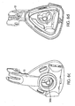
Figures 14a to 15j does not include abaffle 161, it does incorporate other advantages of the invention, including its low profile. An embodiment of the present invention, a "deep"baffle 161 for use inmask assemblies 5 with large breathing cavities 35, is shown inFigures 16a and 16b . -
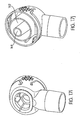
Figures 30a-30d show a swivel elbow in accordance with an alternative embodiment of the invention similar to the embodiment shown inFigures 26a, 26b ,27a-27j . In this embodiment there are two "C"-shaped baffles 161 (Figure 30c ). Air enters the elbow from a blower via astem 166 and is directed to turn through approximately 90 degrees and passes into the mask cavity via theintake port 162 which is located in the center of the elbow. (Figures 30b and 30d ). Air from the mask cavity passes out through theexhaust ports 164 which are located on the sides of the elbow and into vent cavity 308 (Figures 30a and 30d ). - In order to provide sufficient exhaust flow, it is desirable that the
exhaust port 164 have a low flow impedance. One way to achieve this is to have as large a cross-sectional area for theexhaust port 164 as possible. However, within a given elbow design, increasing the cross-sectional area of theexhaust port 164 comes at the expense of theinlet port 162. It is also desirable to have as low a flow impedance in theinlet port 162 as possible. Hence in designing theelbow 160, one must take into account the two apparently conflicting design goals. - In one embodiment the
baffle 161 of theelbow 160 extends into themask frame 10 and is molded in one piece. In another embodiment, thebaffle 161 is split between theswivel elbow 160 and themask frame 10, and the combination of the two provides abaffle 161 of sufficient length. In the latter embodiment, theswivel elbow 160 is suitable for use with shallow mask frames 10 that do not require a longoverall baffle 161. - In another form, the
baffle 161 is partly formed by theelbow 160 and partly by theframe 10. This configuration can be created in different forms or baffle shapes. When thebaffle 161 is formed from the combination ofelbow 160 andframe 10, it is possible to create a modular elbow design which can be used with a variety of different mask systems. In order to form abaffle 161 from the combination offrame 10 andelbow 160, acircular ring 400 is added to the frame. - The
ring 400 extends the depth of abaffle 161 into the cavity 35 of themask frame 10. In this way, the likelihood that fresh inlet air short circuits the mask cavity 35 is reduced. An end of the ring is close to the edge of the user's nose and hence this configuration assists to direct exhaled air from the nose towards theexhaust port 164. The use of aring 400 molded into theframe 10 obviates the need to extend thebaffle 161 of theswivel elbow 160 into themask frame 10. While a long baffled elbow is suitable for mask assemblies with large cavities, it may not be suitable for mask assemblies with shallow cavities, since it may interfere with a patient's nose. Hence by the use of the combination ofmask frame 10 withring 400 and anelbow 160 with a short baffle, thesame elbow 160 can be used on both shallow and large cavitied mask assemblies. - In one form of the invention, the
baffle 161 is formed within a cylindrical portion of theelbow 160 adapted for connection to the frame. In the embodiment of the invention, shown inFigures 20a and21 a to 21 j, thebaffle 161 defines a centrally locatedexhaust port 164. Air from the blower passes around the outside of theexhaust port 164. - The construction of the
elbow 160 in combination with the angle between the two generally cylindrical portions of theelbow 160 leads to a potential dead spot within the blower airflow path. Potential dead spots within the blower flow path represent an opportunity for an exhaust flow path. Hence in one form of the invention, e.g., seeFigs. 4a-4c , the exhaust flow path is positioned within theelbow 160 in what would otherwise be a dead spot for blower flow. Thus the cross-sectional area of the exhaust flow path can be increased without having a significant impact on the impedance of the blower flow path and/or an adverse effect on the undesirable noise that may be produced during washout. In this way, it is possible to increase the cross-sectional area of the exhaust flow path from 40% to 60% of the total cross-sectional area (equal to the area of the exhaust flow path and the area of blower flow path) at the entrance to the mask cavity 35. - Another advantage of the
baffle 161 in accordance with the invention is that it does not present a significant flow impedance for the blower flow. While a variety of different baffle designs are possible, those which impede the flow path create a resistance to flow from the blower, causing a large pressure drop along theelbow 160 than would otherwise be the case. The larger the pressure drop in the elbow, the harder the blower must work in order to provide air at a given positive pressure. The harder the blower must work, the more noise is created by the blower, which makes it more difficult for a patient to sleep. - In one form of the invention, the
elbow 160 comprises two cylindrical portions, a first portion adapted for connection to anair delivery tube 168 and having a first axis; and a second portion adapted for connection to themask frame 10 and having a second axis, wherein the two axes are disposed at an interior angle of about 100 degrees. This contrasts with prior art elbows where two corresponding axes are disposed at an interior angle of 90 degrees. - A further advantage of a
swivel elbow 160 in accordance with the invention is that it has a low height (the perpendicular distance it extends from the frame). This reduces the visual impact of theswivel elbow 160, reduces the bending moment of theswivel elbow 160 and reduces the "lever arm" effect of theswivel elbow 160. -
Figures 5a to 5d show various views of therespiratory mask assembly 10 according to one embodiment of the present invention.Figure 6a to 6m show several views of therespiratory mask assembly 10.Figures 7a to 7i show several views of theswivel elbow 160. The dimensions shown inFigures 5a to 7i are preferred illustrative embodiments that may be varied up to ± 20%, and preferably ± 10%, in embodiments. - Other advantages of a swivel elbow and
mask frame 10 in accordance with a preferred embodiment of the invention include providing: (i) sufficient inlet area and optimized shape such that flow into themask assembly 5 is not impeded; and (ii) sufficient outlet flow area that has, in addition, a smooth profile and no restrictions other than a final smooth tapered exit to provide a quiet vent. The latter advantage has been difficult to achieve prior to the present invention. - While the invention has been described with reference to a nasal mask, it is applicable to a nose and mouth mask, or mouth mask. Furthermore, while the invention has been described with reference to a
swivel elbow 160, it is applicable to fixed elbows. In addition, while one form of the invention is applicable to acushion 30 which includes agusset portion 32, other forms of the invention can be used withcushions 30 that do not include agusset portion 32. - It can thus be appreciated that the aspects of the present invention have been fully and effectively described. The foregoing specific embodiments have been provided to illustrate the structural and functional principles of the present invention, and are not intended to be limiting.
Claims (28)
- An elbow (160), for a respiratory mask, comprising:(a) a first portion, having a first axis and being adapted for connection to the air delivery conduit;(b) a second portion, having a second axis and being adapted for connection to a frame (10) of the respiratory mask; and(c) a vent constructed and arranged to allow the passage of air from an interior of the respiratory mask to atmosphere;wherein the elbow further defines:(i) an inlet port (162) to deliver incoming gas in a first direction to a breathing cavity (35) defined by the mask, and(ii) an exhaust port (164) separated from the inlet port (162) by at least one baffle (161),characterised in that the baffle 161 has at least one curved portion, as viewed along an end of the second portion provided to the frame (10) of the mask, and
wherein the baffle (161) is configured to direct exhaust gas away from the nasal breathing cavity (35) via the vent in a second direction that is substantially opposite to the first direction and substantially parallel to the second axis. - The elbow (160) according to claim 1, wherein the at least one baffle (161) comprises a first and a second baffle situated across from one another.
- The elbow (160) according to any one of claims 1 or 2, wherein the baffle (161) is oriented in the elbow about a center line passing from a top of the elbow (160) to a bottom of the elbow (160) such that a bottom of the baffle (161) is aligned with the bottom of the elbow (160).
- The elbow (160) according to any one of claims 1-3, wherein the exhaust port (164) is completely surrounded by the inlet port (162).
- The elbow (160) according to any one of claims 1-4, wherein the baffle (161) is substantially circular.
- The elbow (160) according to any one of claims 1-5, wherein the baffle (161) is oriented in the elbow (160) about a center line passing from a right side of the elbow (160) to a left side of the elbow (160).
- The elbow (160) according to any one of claims 1-6, wherein the baffle (161) further comprises a protrusion adapted to protrude into a breathing cavity of the mask.
- The elbow (160) according to any one of claims 1-7, wherein the end of the second portion of the elbow (160) further comprises:iii) a resilient collar that substantially surrounds a mating portion to define a receiving space between the collar and the mating portion, and wherein the collar is configured to flex outwardly upon entry of a flange, formed on the mask, into the receiving space until the second end portion reaches an operative position in which the collar flexes inwardly by virtue of the resiliency thereof so as to lock the flange with respect to the collar and thereby detachably couple the elbow (160) to the mask.
- The elbow (160) according to claim 8, wherein the mating portion extends beyond the collar to facilitate alignment of the end of the second portion of the elbow (160) with respect to the mask.
- The elbow (160) according to any one of claims 8 or 9, wherein the elbow (160) further comprises release portions on each side of the collar that are flexed towards one another to move the collar outwardly so as to allow the flange to move out of the receiving space to detach the elbow (160) from the mask.
- The elbow (160) according to any one of claims 1-10, further comprising:c) a removable vent cover detachably connected to the elbow (160), wherein the vent cover includes a main body and at least one vent aperture for gas washout
- The elbow (160) according to claim 11, wherein the vent cover is made of a resilient material.
- The elbow (160) according to any one of claims 1-12, wherein the at least one baffle (161) is M-shaped, V-shaped or C-shaped.
- The elbow according to any one of claims 1-12, wherein the exhaust port (164) increases in area along the second direction.
- A respiratory mask assembly (5) comprising:a) a mask frame (10) further comprising at least one aperture (42);b) a cushion (30), andc) an elbow (160) according to any one of claims 1-14.
- The mask assembly according to claim 15, wherein the aperture has a diameter between about 20 mm to about 40 mm, preferably between about 25 mm to about 30 mm, and more preferably about 28 mm.
- The mask assembly according to any one of claims 15-16, wherein the aperture has a generally circular shape.
- The mask assembly according to any one of claims 16-17, wherein the aperture further comprises a ring.
- The mask assembly according to claim 18, wherein the ring further comprises an inner ring.
- The mask assembly according to claim 19, wherein the inner ring is linked to an inner diameter of the aperture by at least one connector.
- The mask assembly according to claim 20, wherein the at least one connector comprises at least one notch adapted to engage the elbow (160).
- The mask assembly according to claim 19, wherein the ring further comprises an outer ring surrounding the inner ring.
- The mask assembly according to claim 22, wherein the outer ring has a diameter between about 20 mm to about 40 mm preferably between about 25 mm to about 30 mm, and most preferably about 24 mm.
- The mask assembly according to claim 19, wherein the inner ring defines a cavity.
- The mask assembly according to claim 24, wherein the cavity has a diameter between about 4 mm to about 12 mm.
- The mask assembly according to claim 25, wherein the cavity has a diameter between about 6 mm to about 10 mm, preferably about 8 mm.
- The mask assembly according to any one of claims 15-26, wherein the cushion is adapted to be inserted into the mask frame to define a cavity surrounding a user's nose.
- The mask assembly according to claim 15, further comprising a ring provided adjacent the aperture, the ring defining a passage that communicates between an inside of the frame and a second passage defined at least in part by the baffle (161) of the elbow (160), to thereby define a combined passage leading from the inside of the frame towards the exhaust port (164).
Applications Claiming Priority (7)
| Application Number | Priority Date | Filing Date | Title |
|---|---|---|---|
| US10/235,846 US6823869B2 (en) | 2001-09-07 | 2002-09-06 | Mask assembly |
| US235846 | 2002-09-06 | ||
| US42469502P | 2002-11-08 | 2002-11-08 | |
| US424695P | 2002-11-08 | ||
| US47492803P | 2003-06-03 | 2003-06-03 | |
| US474928P | 2003-06-03 | ||
| PCT/AU2003/001162 WO2004022147A1 (en) | 2002-09-06 | 2003-09-05 | Elbow for mask assembly |
Publications (3)
| Publication Number | Publication Date |
|---|---|
| EP1545675A1 EP1545675A1 (en) | 2005-06-29 |
| EP1545675A4 EP1545675A4 (en) | 2010-07-14 |
| EP1545675B1 true EP1545675B1 (en) | 2014-03-05 |
Family
ID=31982281
Family Applications (1)
| Application Number | Title | Priority Date | Filing Date |
|---|---|---|---|
| EP03793492.4A Expired - Lifetime EP1545675B1 (en) | 2002-09-06 | 2003-09-05 | Elbow for mask assembly |
Country Status (6)
| Country | Link |
|---|---|
| US (4) | US7011090B2 (en) |
| EP (1) | EP1545675B1 (en) |
| JP (3) | JP4741248B2 (en) |
| AU (1) | AU2003257273A1 (en) |
| NZ (2) | NZ573226A (en) |
| WO (1) | WO2004022147A1 (en) |
Families Citing this family (146)
| Publication number | Priority date | Publication date | Assignee | Title |
|---|---|---|---|---|
| AUPQ104099A0 (en) * | 1999-06-18 | 1999-07-08 | Resmed Limited | Forehead support for facial mask |
| DE20017940U1 (en) | 2000-10-19 | 2000-12-28 | MAP Medizintechnik für Arzt und Patient GmbH & Co KG, 82152 Planegg | Breathing mask for supplying a breathing gas to a mask user and a derivation device for deriving breathing gas |
| ATE532548T1 (en) | 2000-12-22 | 2011-11-15 | Resmed Ltd | BREATHER VALVE FOR FLOW REGULATION |
| US7523754B2 (en) * | 2001-09-07 | 2009-04-28 | Resmed Limited | Cushion for a respiratory mask assembly |
| DE50214539D1 (en) | 2001-10-22 | 2010-08-26 | Map Medizin Technologie Gmbh | Medical mask |
| DE10201682A1 (en) | 2002-01-17 | 2003-07-31 | Map Medizin Technologie Gmbh | The breathing mask arrangement |
| DE10151984C5 (en) | 2001-10-22 | 2008-07-17 | Map Medizin-Technologie Gmbh | Application device for a breathing mask arrangement |
| US6892729B2 (en) | 2001-11-20 | 2005-05-17 | Fisher & Paykel Healthcare Limited | Patient interfaces |
| US8997742B2 (en) | 2002-04-23 | 2015-04-07 | Resmed Limited | Ergonomic and adjustable respiratory mask assembly with cushion |
| AUPS192602A0 (en) | 2002-04-23 | 2002-05-30 | Resmed Limited | Nasal mask |
| US7743767B2 (en) | 2002-04-23 | 2010-06-29 | Resmed Limited | Ergonomic and adjustable respiratory mask assembly with frame |
| USD485905S1 (en) | 2002-08-09 | 2004-01-27 | Resmed Limited | Nasal mask |
| NZ573226A (en) | 2002-09-06 | 2010-07-30 | Resmed Ltd | Elbow for respiratory mask assembly |
| EP3009159B1 (en) | 2002-09-06 | 2020-02-19 | ResMed Pty Ltd | Forehead pad for respiratory mask |
| NZ553302A (en) * | 2002-11-06 | 2008-10-31 | Resmed Ltd | Mask assembly with frame that can be flexed about longitudinal axis |
| USD496098S1 (en) | 2002-11-08 | 2004-09-14 | Resmed Limited | Swivel elbow for mask assembly |
| US9155855B2 (en) | 2002-12-06 | 2015-10-13 | Fisher & Paykel Healthcare Limited | Mouthpiece |
| NZ589793A (en) | 2003-02-21 | 2011-12-22 | Resmed Ltd | Nozzle configuration of nasal cushion for respiratory assistance mask |
| WO2004096332A1 (en) | 2003-05-02 | 2004-11-11 | Resmed Limited | A mask system |
| CN1901961B (en) | 2003-12-31 | 2010-12-22 | 雷斯梅德有限公司 | Small-sized mouth-nose patient interface |
| DE102004002125B4 (en) * | 2004-01-14 | 2017-11-16 | Löwenstein Medical Technology S.A. | Apparatus for ventilation |
| WO2005079726A1 (en) | 2004-02-23 | 2005-09-01 | Fisher & Paykel Healthcare Limited | Breathing assistance apparatus |
| US9072852B2 (en) | 2004-04-02 | 2015-07-07 | Fisher & Paykel Healthcare Limited | Breathing assistance apparatus |
| WO2005094928A1 (en) | 2004-04-02 | 2005-10-13 | Fisher & Paykel Healthcare Limited | Breathing assistance apparatus |
| JP2007532205A (en) | 2004-04-15 | 2007-11-15 | レスメド リミテッド | Positive pressure breathing device conduit |
| US8807135B2 (en) * | 2004-06-03 | 2014-08-19 | Resmed Limited | Cushion for a patient interface |
| CN106110464B (en) * | 2004-06-16 | 2019-03-12 | 瑞思迈有限公司 | The cushion of respiratory mask assembly |
| AU2012201085B2 (en) * | 2004-06-16 | 2014-04-17 | ResMed Pty Ltd | Cushion for a Respiratory Mask Assembly |
| US7845352B2 (en) * | 2004-07-20 | 2010-12-07 | Carefusion 205, Inc. | Flexible CPAP mask |
| AU2005263206A1 (en) * | 2004-07-23 | 2006-01-26 | Resmed Limited | A swivel elbow for a patient interface |
| US8496004B2 (en) * | 2004-08-02 | 2013-07-30 | Resmed R&D Germany Gmbh | Device for evacuating breathing gas from the interior of a breathing mask, and breathing mask arrangement comprising said device |
| EP2388037B8 (en) * | 2004-09-03 | 2016-09-21 | Löwenstein Medical Technology GmbH + Co. KG | Respiratory mask |
| US7624735B2 (en) * | 2004-09-21 | 2009-12-01 | Respironics Respiratory Drug Delivery (Uk) Ltd | Cheek-mounted patient interface |
| US7237551B2 (en) | 2004-12-22 | 2007-07-03 | Ric Investments, Llc. | Cushion for a patient interface |
| ES2556590T3 (en) | 2005-01-12 | 2016-01-19 | Resmed Limited | Patient interface cushion |
| AU2016204360B2 (en) * | 2005-01-12 | 2018-08-23 | ResMed Pty Ltd | Cushion for Patient Interface |
| EP1841484A4 (en) | 2005-01-12 | 2009-12-02 | Resmed Ltd | Respiratory mask having gas washout vent and method for making the mask |
| US7546837B2 (en) * | 2005-03-16 | 2009-06-16 | Ric Investments, Llc | Interface with rolling diaphragm |
| US9901703B2 (en) * | 2005-04-01 | 2018-02-27 | Resmed Limited | Mask pressure regulation in CPAP treatment and assisted respiration by dynamic control of mask vent flow |
| EP1883455A4 (en) * | 2005-05-20 | 2011-03-02 | Resmed Ltd | Elbow for mask system |
| US20060266365A1 (en) * | 2005-05-31 | 2006-11-30 | Resmed Limited | Vent cover for a mask assembly |
| EP1890755B1 (en) | 2005-06-06 | 2019-12-25 | ResMed Pty Ltd | Mask system |
| US7827987B2 (en) | 2005-06-17 | 2010-11-09 | Nellcor Puritan Bennett Llc | Ball joint for providing flexibility to a gas delivery pathway |
| US7849855B2 (en) | 2005-06-17 | 2010-12-14 | Nellcor Puritan Bennett Llc | Gas exhaust system for a gas delivery mask |
| US7900630B2 (en) | 2005-06-17 | 2011-03-08 | Nellcor Puritan Bennett Llc | Gas delivery mask with flexible bellows |
| US7490608B2 (en) | 2005-06-17 | 2009-02-17 | Nellcorr Puritan Bennett Llc | System and method for adjusting a gas delivery mask |
| USD557408S1 (en) | 2005-10-07 | 2007-12-11 | Resmed Limited | Mask assembly |
| NZ565507A (en) | 2005-10-14 | 2011-06-30 | Resmed Ltd | Mask with cushion having lip which in use deflects against frame of mask |
| WO2007045008A1 (en) * | 2005-10-17 | 2007-04-26 | Resmed Limited | Anti-asphyxia valve assembly for respiratory mask |
| NZ612787A (en) | 2005-10-25 | 2015-01-30 | Resmed Ltd | Interchangeable mask assembly |
| WO2007053878A1 (en) * | 2005-11-08 | 2007-05-18 | Resmed Ltd | Nasal assembly |
| US20080053446A1 (en) * | 2006-03-31 | 2008-03-06 | Tiara Medical Systems, Inc. | Adjustable cpap mask assembly |
| FR2899483B1 (en) * | 2006-04-06 | 2008-05-30 | Georges Boussignac | ARTIFICIAL BREATHING DEVICE FOR PATIENTS WITH HYPOXEMIA OR ANOXEMIA |
| WO2007143792A1 (en) | 2006-06-16 | 2007-12-21 | Resmed Ltd | Elbow assembly |
| DE202007019687U1 (en) | 2006-07-14 | 2015-07-14 | Fisher & Paykel Healthcare Ltd. | Respiratory support device |
| EP2042209B1 (en) | 2006-07-18 | 2013-10-16 | Teijin Pharma Limited | Respiratory nose mask system |
| EP2046430B1 (en) | 2006-07-28 | 2016-04-20 | ResMed Ltd. | Delivery of respiratory therapy |
| NZ612086A (en) * | 2006-07-28 | 2014-12-24 | Resmed Ltd | Delivery of respiratory therapy |
| EP2101855B1 (en) * | 2006-12-15 | 2013-08-21 | ResMed Limited | Respiratory Mask |
| ES2569880T3 (en) * | 2006-12-15 | 2016-05-12 | Resmed Ltd. | Administration of respiratory therapy |
| US8517023B2 (en) | 2007-01-30 | 2013-08-27 | Resmed Limited | Mask system with interchangeable headgear connectors |
| NZ567460A (en) | 2007-04-19 | 2010-02-26 | Resmed Ltd | Cushion and cushion to frame assembly mechanism for patient interface |
| JP5912250B2 (en) * | 2007-05-02 | 2016-04-27 | アールアイシー・インベストメンツ・エルエルシー | Cushion for patient interface |
| US8875709B2 (en) * | 2007-05-10 | 2014-11-04 | Resmed Limited | Mask assembly |
| JP2008310110A (en) * | 2007-06-15 | 2008-12-25 | Konica Minolta Business Technologies Inc | Image forming apparatus |
| EP2452715B1 (en) | 2007-07-30 | 2021-12-29 | ResMed Pty Ltd | Patient interface |
| EP3858411B1 (en) * | 2007-08-24 | 2024-05-29 | ResMed Pty Ltd | Mask vent |
| US8573201B2 (en) | 2007-10-22 | 2013-11-05 | Resmed Limited | Patient interface systems |
| WO2011014931A1 (en) | 2009-08-07 | 2011-02-10 | Resmed Ltd | Patient interface systems |
| US11331447B2 (en) | 2008-03-04 | 2022-05-17 | ResMed Pty Ltd | Mask system with snap-fit shroud |
| WO2009109004A1 (en) * | 2008-03-04 | 2009-09-11 | Resmed Ltd | An interface including a foam cushioning element |
| EP2837398B1 (en) | 2008-03-04 | 2018-08-22 | ResMed Limited | Mask system |
| WO2009108994A1 (en) * | 2008-03-04 | 2009-09-11 | Resmed Ltd | A foam respiratory mask |
| CN102015000B (en) | 2008-05-07 | 2014-05-14 | 皇家飞利浦电子股份有限公司 | Exhaust assembly |
| US10792451B2 (en) | 2008-05-12 | 2020-10-06 | Fisher & Paykel Healthcare Limited | Patient interface and aspects thereof |
| US10258757B2 (en) | 2008-05-12 | 2019-04-16 | Fisher & Paykel Healthcare Limited | Patient interface and aspects thereof |
| CN106039505A (en) | 2008-06-04 | 2016-10-26 | 瑞思迈有限公司 | Patient interface systems |
| US8905031B2 (en) | 2008-06-04 | 2014-12-09 | Resmed Limited | Patient interface systems |
| EP3053623B1 (en) | 2008-06-05 | 2019-08-14 | ResMed Pty Ltd | Treatment of respiratory conditions |
| US11660413B2 (en) | 2008-07-18 | 2023-05-30 | Fisher & Paykel Healthcare Limited | Breathing assistance apparatus |
| EP2145645B1 (en) * | 2008-07-18 | 2012-01-04 | Fisher & Paykel Healthcare Limited | Breathing assistance apparatus |
| AU2014202233B2 (en) * | 2008-07-18 | 2015-09-17 | Fisher & Paykel Healthcare Limited | Breathing assistance apparatus |
| NZ770159A (en) * | 2008-09-12 | 2022-07-01 | ResMed Pty Ltd | A foam-based interfacing structure method and apparatus |
| EP2349428B1 (en) | 2008-10-10 | 2017-09-20 | Fisher & Paykel Healthcare Limited | Nasal pillows for a patient interface |
| US9095673B2 (en) | 2008-12-15 | 2015-08-04 | Resmed Limited | Unobtrusive nasal mask |
| EP2213324B1 (en) | 2009-01-30 | 2016-07-27 | ResMed R&D Germany GmbH | Patient interface structure and method/tool for manufacturing same |
| US20100282264A1 (en) * | 2009-05-05 | 2010-11-11 | Hsiner Company, Ltd. | Respiratory mask having a damping ring |
| CN105944209B (en) | 2009-05-29 | 2019-04-19 | 瑞思迈有限公司 | nasal mask system |
| US10137271B2 (en) | 2009-11-18 | 2018-11-27 | Fisher & Paykel Healthcare Limited | Nasal interface |
| NZ713055A (en) | 2010-09-30 | 2017-04-28 | Resmed Ltd | Mask system |
| EP2621572B1 (en) | 2010-09-30 | 2019-11-06 | ResMed Pty Ltd | Patient interface systems |
| EP2624903B1 (en) | 2010-10-08 | 2018-05-16 | Fisher & Paykel Healthcare Limited | Breathing assistance apparatus |
| JP2013540032A (en) * | 2010-10-22 | 2013-10-31 | コーニンクレッカ フィリップス エヌ ヴェ | Exhaust gas assembly for patient interface devices cross-referenced with related applications |
| CA2814785A1 (en) * | 2010-12-01 | 2012-07-19 | Southmedic Incorporated | Gas delivery mask for medical use |
| US20120234326A1 (en) * | 2011-01-14 | 2012-09-20 | Resmed Limited | Mask system |
| DE112012007300B4 (en) | 2011-04-15 | 2024-04-25 | Fisher & Paykel Healthcare Ltd. | Interface with a movable nose bridge |
| US10603456B2 (en) | 2011-04-15 | 2020-03-31 | Fisher & Paykel Healthcare Limited | Interface comprising a nasal sealing portion |
| US9687620B2 (en) | 2011-11-07 | 2017-06-27 | Koninklijke Philips N.V. | Patient interface with snap-fit connector |
| US8434589B1 (en) * | 2011-11-14 | 2013-05-07 | Xerox Corporation | Obstruction device for reducing noise emitted from a blower |
| US9333318B2 (en) | 2012-04-13 | 2016-05-10 | Fresca Medical, Inc. | Sleep apnea device |
| US9492086B2 (en) | 2012-03-21 | 2016-11-15 | Fresca Medical, Inc. | Apparatus, systems, and methods for treating obstructive sleep apnea |
| CN104203324B (en) * | 2012-03-27 | 2017-07-14 | 皇家飞利浦有限公司 | There is provided improved skin nice and cool user interface device |
| US9889267B2 (en) | 2012-07-27 | 2018-02-13 | Resmed Limited | Patient interface |
| US12390612B2 (en) | 2012-07-27 | 2025-08-19 | ResMed Pty Ltd | Patient interface with elastic headgear |
| US9974915B2 (en) | 2012-07-27 | 2018-05-22 | Resmed Limited | Elastic headgear |
| GB2553475B8 (en) | 2012-08-08 | 2019-01-02 | Fisher & Paykel Healthcare Ltd | Headgear for patient interface |
| EP2892596B1 (en) | 2012-09-04 | 2023-07-26 | Fisher&Paykel Healthcare Limited | Valsalva mask |
| DE102012020917A1 (en) * | 2012-10-25 | 2014-04-30 | Dräger Medical GmbH | Elbow for a respiratory mask |
| WO2014091370A1 (en) * | 2012-12-14 | 2014-06-19 | Koninklijke Philips N.V. | Respiratory interface device customization utilizing a generic cushion template |
| CN118807059A (en) | 2013-01-16 | 2024-10-22 | 瑞思迈私人有限公司 | Patient interface and method of making the same |
| EP2945680B1 (en) | 2013-01-18 | 2019-10-09 | ResMed Pty Ltd | Patient interface |
| EP2953538B1 (en) * | 2013-02-11 | 2018-10-17 | Monitor Mask Inc. | Oxygen face mask and component system |
| US20140238401A1 (en) * | 2013-02-22 | 2014-08-28 | Walter Jent Paschall | Cpap system |
| CA2844454C (en) | 2013-03-08 | 2017-07-11 | Teleflex Medical Incorporated | Exhalation scavenging therapy mask |
| USD749205S1 (en) | 2013-03-08 | 2016-02-09 | Fresca Medical, Inc. | Sleep apnea device |
| US10662408B2 (en) | 2013-03-14 | 2020-05-26 | Inguran, Llc | Methods for high throughput sperm sorting |
| US10371622B2 (en) | 2013-03-14 | 2019-08-06 | Inguran, Llc | Device for high throughput sperm sorting |
| US9757726B2 (en) | 2013-03-14 | 2017-09-12 | Inguran, Llc | System for high throughput sperm sorting |
| FR3004953A1 (en) * | 2013-04-29 | 2014-10-31 | Louis Pradin | DEVICE FOR AVOIDING THE TRANSMISSION OF CONTAGIOUS DISEASES WITH THE EXTRACTION OF RESPIRATORY BREATHING AIR EXHAUSTION FOR A PERSON IN A BED WITH A SIDE OF A PATIENT UNDER TREATMENT OF RESPIRATORY ASSISTANCE FOR THE APNEA OF SLEEP AND TO AVOID THIS SICK FROM ULCERATIONS TO THE CORNE OF HIS EYES. |
| USD742501S1 (en) | 2013-07-18 | 2015-11-03 | Fresca Medical, Inc. | Sleep apnea device |
| USD742502S1 (en) | 2013-07-18 | 2015-11-03 | Fresca Medical, Inc. | Sleep apnea device |
| USD743021S1 (en) | 2013-07-18 | 2015-11-10 | Fresca Medical, Inc. | Sleep apnea device |
| USD745139S1 (en) | 2013-08-16 | 2015-12-08 | Fresca Medical, Inc. | Sleep apnea device |
| JP6629726B2 (en) | 2013-11-15 | 2020-01-15 | レスメド・プロプライエタリー・リミテッド | Patient interface and method for forming a patient interface |
| US10058672B2 (en) | 2014-05-21 | 2018-08-28 | Atom Medical Corporation | Gas supply mask apparatus |
| JP6271346B2 (en) * | 2014-06-12 | 2018-01-31 | アトムメディカル株式会社 | Gas supply mask device |
| USD759230S1 (en) | 2014-05-30 | 2016-06-14 | Fresca Medical, Inc. | Airflow generator for a sleep apnea system |
| EP2954919A1 (en) * | 2014-06-11 | 2015-12-16 | Air Liquide Medical Systems | Respiratory mask with venting holes |
| WO2016009393A1 (en) | 2014-07-18 | 2016-01-21 | Fisher & Paykel Healthcare Limited | Headgear clip arrangement |
| CN111939417B (en) | 2014-08-25 | 2023-07-04 | 费雪派克医疗保健有限公司 | Respiratory masks and related parts, components or subassemblies |
| CN104872864A (en) * | 2014-12-10 | 2015-09-02 | 深圳市三恩科技有限公司 | Protective air supply mask with air purifying function |
| US11173270B2 (en) | 2015-03-04 | 2021-11-16 | Fisher & Paykel Healthcare Limited | Mask system headgear |
| JP6283325B2 (en) * | 2015-03-09 | 2018-02-21 | アトムメディカル株式会社 | Gas supply mask device |
| CN107921229A (en) * | 2015-07-20 | 2018-04-17 | 瑞思迈有限公司 | Patient Interface with Volume Reduced Members |
| US10675430B2 (en) | 2015-09-23 | 2020-06-09 | ResMed Pty Ltd | Elbow assembly |
| USD882066S1 (en) | 2016-05-13 | 2020-04-21 | Fisher & Paykel Healthcare Limited | Frame for a breathing mask |
| USD863545S1 (en) * | 2016-11-30 | 2019-10-15 | ResMed Pty Ltd | Air delivery adapter for respiratory mask |
| USD895102S1 (en) | 2016-11-30 | 2020-09-01 | ResMed Pty Ltd | Air delivery adapter for respiratory mask |
| USD823455S1 (en) | 2017-02-23 | 2018-07-17 | Fisher & Paykel Healthcare Limited | Cushion assembly for breathing mask assembly |
| USD823454S1 (en) | 2017-02-23 | 2018-07-17 | Fisher & Paykel Healthcare Limited | Cushion assembly for breathing mask assembly |
| USD824020S1 (en) | 2017-02-23 | 2018-07-24 | Fisher & Paykel Healthcare Limited | Cushion assembly for breathing mask assembly |
| TWI737934B (en) * | 2018-09-14 | 2021-09-01 | 雃博股份有限公司 | Respiratory mask |
| CN109568756A (en) * | 2018-12-29 | 2019-04-05 | 天津觉明科技有限公司 | Breathing mask and ventilation therapy equipment |
| USD999368S1 (en) * | 2019-12-02 | 2023-09-19 | Primed Halberstadt Medizintechnik Gmbh | Speaking valve with breathing filter for a tracheal tube |
| TWI770844B (en) * | 2021-02-26 | 2022-07-11 | 雃博股份有限公司 | Patient interface |
| US20250161620A1 (en) * | 2023-11-21 | 2025-05-22 | Dcstar Inc. | Frame assembly directly connected to a frame and a short tube |
Family Cites Families (78)
| Publication number | Priority date | Publication date | Assignee | Title |
|---|---|---|---|---|
| US1081745A (en) * | 1912-05-03 | 1913-12-16 | White S Dental Mfg Co | Nasal inhaler. |
| US2313999A (en) * | 1942-06-30 | 1943-03-16 | Air Reduction | Apparatus for administering oxygen |
| DE1102976B (en) * | 1954-01-16 | 1961-03-23 | Chirana Praha Np | Valve piece with an inhalation valve and an exhalation valve intended for anesthesia devices or devices for artificial respiration |
| US3724499A (en) * | 1971-06-03 | 1973-04-03 | Fmc Corp | Anti-cavitation system for fluid loading arms |
| US4266540A (en) * | 1978-10-13 | 1981-05-12 | Donald Panzik | Nasal oxygen therapy mask |
| US4446864A (en) * | 1980-07-10 | 1984-05-08 | Watson Robert L | Emergency ventilation tube |
| SE8008962L (en) * | 1980-12-18 | 1982-06-19 | Erik Allan Lindkvist | DEVICE FOR ANCESTIC MASK |
| WO1982003548A1 (en) * | 1981-04-24 | 1982-10-28 | Sullivan Colin Edward | Device for treating snoring sickness |
| US4655213A (en) * | 1983-10-06 | 1987-04-07 | New York University | Method and apparatus for the treatment of obstructive sleep apnea |
| US4676241A (en) * | 1984-01-16 | 1987-06-30 | W.L.G. Technology | Ventilation tube swivel |
| US4713844A (en) * | 1986-07-16 | 1987-12-22 | Gentex Corporation | Protective helmet with face mask sealing means |
| US5199424A (en) * | 1987-06-26 | 1993-04-06 | Sullivan Colin E | Device for monitoring breathing during sleep and control of CPAP treatment that is patient controlled |
| US5065756A (en) * | 1987-12-22 | 1991-11-19 | New York University | Method and apparatus for the treatment of obstructive sleep apnea |
| US5243971A (en) * | 1990-05-21 | 1993-09-14 | The University Of Sydney | Nasal mask for CPAP having ballooning/moulding seal with wearer's nose and facial contours |
| FR2682043A1 (en) * | 1991-10-03 | 1993-04-09 | Intertechnique Sa | RESPIRATORY EQUIPMENT WITH ORO-NASAL MASK. |
| EP0634186B1 (en) * | 1993-06-18 | 2000-08-23 | Resmed Limited | Facial breathing mask |
| US5441046A (en) * | 1993-09-29 | 1995-08-15 | Respironics, Inc. | Quick release mechanism for nasal and/or oral gas delivery mask |
| EP1900324B1 (en) * | 1993-11-05 | 2009-06-03 | ResMed Limited | Apparatus for determining patency of the airway |
| US5735271A (en) * | 1994-05-18 | 1998-04-07 | Ballard Medical Products | Multiple access adaptors for monitoring, sampling, medicating, aspirating, and ventilating the respiratory tract of a patient |
| US5694922A (en) * | 1994-05-18 | 1997-12-09 | Ballard Medical Products | Swivel tube connections with hermetic seals |
| US5662101A (en) * | 1995-12-07 | 1997-09-02 | Respironics, Inc. | Respiratory facial mask |
| US5857460A (en) | 1996-03-14 | 1999-01-12 | Beth Israel Deaconess Medical Center, Inc. | Gas-sensing mask |
| US5657752A (en) * | 1996-03-28 | 1997-08-19 | Airways Associates | Nasal positive airway pressure mask and method |
| AUPO126596A0 (en) * | 1996-07-26 | 1996-08-22 | Resmed Limited | A nasal mask and mask cushion therefor |
| AUPO247496A0 (en) | 1996-09-23 | 1996-10-17 | Resmed Limited | Assisted ventilation to match patient respiratory need |
| US6192886B1 (en) * | 1996-10-17 | 2001-02-27 | Hans Rudolph, Inc. | Nasal mask |
| US5921239A (en) * | 1997-01-07 | 1999-07-13 | Sunrise Medical Hhg Inc. | Face mask for patient breathing |
| US5746201A (en) * | 1997-01-23 | 1998-05-05 | Nellcor Puritan-Bennett | CPAP nose mask |
| AUPP855099A0 (en) * | 1999-02-09 | 1999-03-04 | Resmed Limited | Gas delivery connection assembly |
| AUPQ104099A0 (en) | 1999-06-18 | 1999-07-08 | Resmed Limited | Forehead support for facial mask |
| US6412487B1 (en) * | 1997-01-31 | 2002-07-02 | Resmed Limited | Mask cushion and frame assembly |
| AUPO504597A0 (en) | 1997-02-10 | 1997-03-06 | Resmed Limited | A mask and a vent assembly therefor |
| US5937851A (en) * | 1997-02-27 | 1999-08-17 | Respironics, Inc. | Swivel device utilizing bearing clearance to allow carbon dioxide laden exhaust |
| DE29723101U1 (en) | 1997-04-05 | 1998-05-28 | Gottlieb Weinmann Geräte für Medizin und Arbeitsschutz GmbH + Co. KG, 22525 Hamburg | Device for coupling to ventilation masks |
| US6119694A (en) * | 1997-07-24 | 2000-09-19 | Respironics Georgia, Inc. | Nasal mask and headgear |
| US5947121A (en) * | 1997-11-28 | 1999-09-07 | Marshall; Patrick | Tracheotomy tube water blocking system |
| US6119693A (en) * | 1998-01-16 | 2000-09-19 | Resmed Limited | Forehead support for facial mask |
| US5918598A (en) * | 1998-04-10 | 1999-07-06 | Belfer; William A. | Strapless respiratory facial mask for customizing to the wearer's face |
| AUPP366398A0 (en) | 1998-05-22 | 1998-06-18 | Resmed Limited | Ventilatory assistance for treatment of cardiac failure and cheyne-stokes breathing |
| DE19840760C2 (en) * | 1998-09-07 | 2000-07-20 | Map Medizintechnik Gmbh | Ventilator silencer |
| AUPQ102999A0 (en) | 1999-06-18 | 1999-07-08 | Resmed Limited | A connector for a respiratory mask and a respiratory mask |
| AUPP812199A0 (en) * | 1999-01-12 | 1999-02-04 | Resmed Limited | Headgear |
| JP2000233024A (en) * | 1999-02-12 | 2000-08-29 | Shigeo Chikui | Respirator valve device of bellows-shaped artificial respirator |
| US6338342B1 (en) * | 1999-02-22 | 2002-01-15 | Cabot Safety Intermediate Corporation | Respirator headpiece and release mechanism |
| US6347631B1 (en) * | 1999-11-09 | 2002-02-19 | Mallinckrodt, Inc. | Cantilever device and method for breathing devices and the like |
| US6412488B1 (en) * | 1999-05-12 | 2002-07-02 | Respironics, Inc. | Low contact nasal mask and system using same |
| US6505623B1 (en) * | 1999-06-04 | 2003-01-14 | Mallinckrodt Inc. | Hat-held respiratory mask |
| US6631718B1 (en) * | 1999-06-08 | 2003-10-14 | Sleepnet Corporation | Air mask with seal |
| US6467483B1 (en) * | 1999-07-28 | 2002-10-22 | Respironics, Inc. | Respiratory mask |
| US6435181B1 (en) * | 1999-08-30 | 2002-08-20 | Sunrise Medical Hhg Inc. | Respiratory mask with adjustable exhaust vent |
| US20010032648A1 (en) | 2000-03-03 | 2001-10-25 | Bernadette Jestrabek-Hart | Exhaust airway for nasal continuous positive airway pressure mask |
| US6595212B1 (en) * | 2000-04-17 | 2003-07-22 | Richard J. Arnott | Method and apparatus for maintaining airway patency |
| US6581594B1 (en) * | 2000-05-15 | 2003-06-24 | Resmed Limited | Respiratory mask having gas washout vent and gas washout vent for respiratory mask |
| US6450166B1 (en) * | 2000-05-17 | 2002-09-17 | Southmedic Incorporated | Patient oxygen delivery system |
| ES2657501T3 (en) * | 2000-06-14 | 2018-03-05 | Fisher & Paykel Healthcare Limited | Nasal mask |
| US6986352B2 (en) | 2000-06-22 | 2006-01-17 | Resmed Limited | Mask with gusset |
| US6530373B1 (en) * | 2000-08-04 | 2003-03-11 | Mallinckrodt Inc. | Respirator mask |
| US6595207B1 (en) | 2000-09-11 | 2003-07-22 | Southmedic Incorporated | Oxygen diffuser for patient oxygen delivery system |
| US6418928B1 (en) * | 2000-09-25 | 2002-07-16 | Mallinckrodt Inc. | Multi-seal respirator mask |
| US6508249B2 (en) * | 2000-10-05 | 2003-01-21 | Vital Signs, Inc. | Connecting apparatus for placing fluid flow paths in fluid communication |
| ATE532548T1 (en) | 2000-12-22 | 2011-11-15 | Resmed Ltd | BREATHER VALVE FOR FLOW REGULATION |
| US7007696B2 (en) * | 2001-05-18 | 2006-03-07 | Tiara Medical Systems, Inc. | Mask cushion and method of using same |
| US6851425B2 (en) * | 2001-05-25 | 2005-02-08 | Respironics, Inc. | Exhaust port assembly for a pressure support system |
| GB0114368D0 (en) * | 2001-06-07 | 2001-08-08 | Smiths Industries Plc | Face masks |
| ATE390945T1 (en) * | 2001-09-07 | 2008-04-15 | Resmed Ltd | MASK ARRANGEMENT |
| US6675796B2 (en) * | 2001-10-12 | 2004-01-13 | Southmedic Incorporated | Lightweight oxygen delivery device for patients |
| US6679265B2 (en) * | 2001-10-25 | 2004-01-20 | Worldwide Medical Technologies | Nasal cannula |
| US6892729B2 (en) | 2001-11-20 | 2005-05-17 | Fisher & Paykel Healthcare Limited | Patient interfaces |
| DE10158066A1 (en) * | 2001-11-27 | 2003-06-05 | Weinmann G Geraete Med | breathing mask |
| US7743767B2 (en) * | 2002-04-23 | 2010-06-29 | Resmed Limited | Ergonomic and adjustable respiratory mask assembly with frame |
| US8997742B2 (en) | 2002-04-23 | 2015-04-07 | Resmed Limited | Ergonomic and adjustable respiratory mask assembly with cushion |
| AUPS192602A0 (en) | 2002-04-23 | 2002-05-30 | Resmed Limited | Nasal mask |
| USD485905S1 (en) | 2002-08-09 | 2004-01-27 | Resmed Limited | Nasal mask |
| NZ573226A (en) * | 2002-09-06 | 2010-07-30 | Resmed Ltd | Elbow for respiratory mask assembly |
| US6874502B1 (en) * | 2003-05-02 | 2005-04-05 | Ramses Nashed | Breathing circuit disconnect warning system and method for using a disconnect system |
| AU2005263206A1 (en) * | 2004-07-23 | 2006-01-26 | Resmed Limited | A swivel elbow for a patient interface |
| EP1883455A4 (en) * | 2005-05-20 | 2011-03-02 | Resmed Ltd | Elbow for mask system |
| US8875709B2 (en) * | 2007-05-10 | 2014-11-04 | Resmed Limited | Mask assembly |
-
2003
- 2003-09-05 NZ NZ573226A patent/NZ573226A/en not_active IP Right Cessation
- 2003-09-05 AU AU2003257273A patent/AU2003257273A1/en not_active Abandoned
- 2003-09-05 US US10/655,621 patent/US7011090B2/en not_active Expired - Lifetime
- 2003-09-05 EP EP03793492.4A patent/EP1545675B1/en not_active Expired - Lifetime
- 2003-09-05 NZ NZ595537A patent/NZ595537A/en not_active IP Right Cessation
- 2003-09-05 JP JP2004569778A patent/JP4741248B2/en not_active Expired - Fee Related
- 2003-09-05 WO PCT/AU2003/001162 patent/WO2004022147A1/en not_active Ceased
-
2005
- 2005-12-30 US US11/320,633 patent/US7316230B2/en not_active Expired - Lifetime
-
2007
- 2007-12-14 US US12/000,601 patent/US8826908B2/en not_active Expired - Lifetime
-
2010
- 2010-05-06 JP JP2010106600A patent/JP5373694B2/en not_active Expired - Lifetime
-
2011
- 2011-08-25 JP JP2011183475A patent/JP5466213B2/en not_active Expired - Fee Related
-
2014
- 2014-09-05 US US14/477,973 patent/US9821134B2/en not_active Expired - Fee Related
Also Published As
| Publication number | Publication date |
|---|---|
| JP2005537905A (en) | 2005-12-15 |
| JP2010162411A (en) | 2010-07-29 |
| JP5373694B2 (en) | 2013-12-18 |
| US9821134B2 (en) | 2017-11-21 |
| NZ595537A (en) | 2013-05-31 |
| WO2004022147A1 (en) | 2004-03-18 |
| US20080099014A1 (en) | 2008-05-01 |
| NZ573226A (en) | 2010-07-30 |
| US7011090B2 (en) | 2006-03-14 |
| JP4741248B2 (en) | 2011-08-03 |
| US7316230B2 (en) | 2008-01-08 |
| JP5466213B2 (en) | 2014-04-09 |
| US20140373848A1 (en) | 2014-12-25 |
| US8826908B2 (en) | 2014-09-09 |
| US20040112385A1 (en) | 2004-06-17 |
| JP2011229997A (en) | 2011-11-17 |
| US20060102185A1 (en) | 2006-05-18 |
| EP1545675A4 (en) | 2010-07-14 |
| EP1545675A1 (en) | 2005-06-29 |
| AU2003257273A1 (en) | 2004-03-29 |
Similar Documents
| Publication | Publication Date | Title |
|---|---|---|
| EP1545675B1 (en) | Elbow for mask assembly | |
| US11478597B2 (en) | Nasal assembly | |
| US20240342423A1 (en) | Conduit connector assembly of a patient interface, an anti-asphyxia valve for a conduit connector assembly and a connector | |
| US10842957B2 (en) | Nasal assembly | |
| US8333199B2 (en) | High flow therapy artificial airway interfaces and related methods | |
| NZ585826A (en) | Elbow with gas diversion baffle for respiratory mask | |
| US20060266365A1 (en) | Vent cover for a mask assembly | |
| JP5795024B2 (en) | Elbow for mask assembly | |
| NZ567374A (en) | Nasal assembly including frame with vent holes |
Legal Events
| Date | Code | Title | Description |
|---|---|---|---|
| PUAI | Public reference made under article 153(3) epc to a published international application that has entered the european phase |
Free format text: ORIGINAL CODE: 0009012 |
|
| 17P | Request for examination filed |
Effective date: 20050405 |
|
| AK | Designated contracting states |
Kind code of ref document: A1 Designated state(s): AT BE BG CH CY CZ DE DK EE ES FI FR GB GR HU IE IT LI LU MC NL PT RO SE SI SK TR |
|
| AX | Request for extension of the european patent |
Extension state: AL LT LV MK |
|
| DAX | Request for extension of the european patent (deleted) | ||
| RAP1 | Party data changed (applicant data changed or rights of an application transferred) |
Owner name: RESMED LIMITED |
|
| A4 | Supplementary search report drawn up and despatched |
Effective date: 20100615 |
|
| RIC1 | Information provided on ipc code assigned before grant |
Ipc: A61M 16/06 20060101AFI20100609BHEP |
|
| 17Q | First examination report despatched |
Effective date: 20101014 |
|
| GRAP | Despatch of communication of intention to grant a patent |
Free format text: ORIGINAL CODE: EPIDOSNIGR1 |
|
| INTG | Intention to grant announced |
Effective date: 20130923 |
|
| GRAS | Grant fee paid |
Free format text: ORIGINAL CODE: EPIDOSNIGR3 |
|
| GRAA | (expected) grant |
Free format text: ORIGINAL CODE: 0009210 |
|
| AK | Designated contracting states |
Kind code of ref document: B1 Designated state(s): AT BE BG CH CY CZ DE DK EE ES FI FR GB GR HU IE IT LI LU MC NL PT RO SE SI SK TR |
|
| REG | Reference to a national code |
Ref country code: GB Ref legal event code: FG4D |
|
| REG | Reference to a national code |
Ref country code: CH Ref legal event code: EP |
|
| REG | Reference to a national code |
Ref country code: AT Ref legal event code: REF Ref document number: 654417 Country of ref document: AT Kind code of ref document: T Effective date: 20140315 |
|
| REG | Reference to a national code |
Ref country code: SE Ref legal event code: TRGR |
|
| REG | Reference to a national code |
Ref country code: IE Ref legal event code: FG4D |
|
| REG | Reference to a national code |
Ref country code: DE Ref legal event code: R096 Ref document number: 60345812 Country of ref document: DE Effective date: 20140410 |
|
| REG | Reference to a national code |
Ref country code: CH Ref legal event code: NV Representative=s name: VOSSIUS AND PARTNER, CH |
|
| REG | Reference to a national code |
Ref country code: AT Ref legal event code: MK05 Ref document number: 654417 Country of ref document: AT Kind code of ref document: T Effective date: 20140305 |
|
| REG | Reference to a national code |
Ref country code: NL Ref legal event code: VDEP Effective date: 20140305 |
|
| PG25 | Lapsed in a contracting state [announced via postgrant information from national office to epo] |
Ref country code: AT Free format text: LAPSE BECAUSE OF FAILURE TO SUBMIT A TRANSLATION OF THE DESCRIPTION OR TO PAY THE FEE WITHIN THE PRESCRIBED TIME-LIMIT Effective date: 20140305 Ref country code: FI Free format text: LAPSE BECAUSE OF FAILURE TO SUBMIT A TRANSLATION OF THE DESCRIPTION OR TO PAY THE FEE WITHIN THE PRESCRIBED TIME-LIMIT Effective date: 20140305 Ref country code: CY Free format text: LAPSE BECAUSE OF FAILURE TO SUBMIT A TRANSLATION OF THE DESCRIPTION OR TO PAY THE FEE WITHIN THE PRESCRIBED TIME-LIMIT Effective date: 20140305 |
|
| PG25 | Lapsed in a contracting state [announced via postgrant information from national office to epo] |
Ref country code: BE Free format text: LAPSE BECAUSE OF FAILURE TO SUBMIT A TRANSLATION OF THE DESCRIPTION OR TO PAY THE FEE WITHIN THE PRESCRIBED TIME-LIMIT Effective date: 20140305 Ref country code: BG Free format text: LAPSE BECAUSE OF FAILURE TO SUBMIT A TRANSLATION OF THE DESCRIPTION OR TO PAY THE FEE WITHIN THE PRESCRIBED TIME-LIMIT Effective date: 20140605 Ref country code: EE Free format text: LAPSE BECAUSE OF FAILURE TO SUBMIT A TRANSLATION OF THE DESCRIPTION OR TO PAY THE FEE WITHIN THE PRESCRIBED TIME-LIMIT Effective date: 20140305 Ref country code: NL Free format text: LAPSE BECAUSE OF FAILURE TO SUBMIT A TRANSLATION OF THE DESCRIPTION OR TO PAY THE FEE WITHIN THE PRESCRIBED TIME-LIMIT Effective date: 20140305 Ref country code: CZ Free format text: LAPSE BECAUSE OF FAILURE TO SUBMIT A TRANSLATION OF THE DESCRIPTION OR TO PAY THE FEE WITHIN THE PRESCRIBED TIME-LIMIT Effective date: 20140305 Ref country code: RO Free format text: LAPSE BECAUSE OF FAILURE TO SUBMIT A TRANSLATION OF THE DESCRIPTION OR TO PAY THE FEE WITHIN THE PRESCRIBED TIME-LIMIT Effective date: 20140305 |
|
| PG25 | Lapsed in a contracting state [announced via postgrant information from national office to epo] |
Ref country code: SK Free format text: LAPSE BECAUSE OF FAILURE TO SUBMIT A TRANSLATION OF THE DESCRIPTION OR TO PAY THE FEE WITHIN THE PRESCRIBED TIME-LIMIT Effective date: 20140305 Ref country code: ES Free format text: LAPSE BECAUSE OF FAILURE TO SUBMIT A TRANSLATION OF THE DESCRIPTION OR TO PAY THE FEE WITHIN THE PRESCRIBED TIME-LIMIT Effective date: 20140305 |
|
| REG | Reference to a national code |
Ref country code: DE Ref legal event code: R097 Ref document number: 60345812 Country of ref document: DE |
|
| PG25 | Lapsed in a contracting state [announced via postgrant information from national office to epo] |
Ref country code: PT Free format text: LAPSE BECAUSE OF FAILURE TO SUBMIT A TRANSLATION OF THE DESCRIPTION OR TO PAY THE FEE WITHIN THE PRESCRIBED TIME-LIMIT Effective date: 20140707 |
|
| PLBE | No opposition filed within time limit |
Free format text: ORIGINAL CODE: 0009261 |
|
| STAA | Information on the status of an ep patent application or granted ep patent |
Free format text: STATUS: NO OPPOSITION FILED WITHIN TIME LIMIT |
|
| PG25 | Lapsed in a contracting state [announced via postgrant information from national office to epo] |
Ref country code: DK Free format text: LAPSE BECAUSE OF FAILURE TO SUBMIT A TRANSLATION OF THE DESCRIPTION OR TO PAY THE FEE WITHIN THE PRESCRIBED TIME-LIMIT Effective date: 20140305 |
|
| 26N | No opposition filed |
Effective date: 20141208 |
|
| REG | Reference to a national code |
Ref country code: DE Ref legal event code: R097 Ref document number: 60345812 Country of ref document: DE Effective date: 20141208 |
|
| PG25 | Lapsed in a contracting state [announced via postgrant information from national office to epo] |
Ref country code: IT Free format text: LAPSE BECAUSE OF FAILURE TO SUBMIT A TRANSLATION OF THE DESCRIPTION OR TO PAY THE FEE WITHIN THE PRESCRIBED TIME-LIMIT Effective date: 20140305 |
|
| PG25 | Lapsed in a contracting state [announced via postgrant information from national office to epo] |
Ref country code: MC Free format text: LAPSE BECAUSE OF FAILURE TO SUBMIT A TRANSLATION OF THE DESCRIPTION OR TO PAY THE FEE WITHIN THE PRESCRIBED TIME-LIMIT Effective date: 20140305 Ref country code: LU Free format text: LAPSE BECAUSE OF FAILURE TO SUBMIT A TRANSLATION OF THE DESCRIPTION OR TO PAY THE FEE WITHIN THE PRESCRIBED TIME-LIMIT Effective date: 20140905 |
|
| PG25 | Lapsed in a contracting state [announced via postgrant information from national office to epo] |
Ref country code: SI Free format text: LAPSE BECAUSE OF FAILURE TO SUBMIT A TRANSLATION OF THE DESCRIPTION OR TO PAY THE FEE WITHIN THE PRESCRIBED TIME-LIMIT Effective date: 20140305 |
|
| REG | Reference to a national code |
Ref country code: IE Ref legal event code: MM4A |
|
| REG | Reference to a national code |
Ref country code: FR Ref legal event code: PLFP Year of fee payment: 13 |
|
| PG25 | Lapsed in a contracting state [announced via postgrant information from national office to epo] |
Ref country code: IE Free format text: LAPSE BECAUSE OF NON-PAYMENT OF DUE FEES Effective date: 20140905 |
|
| PGFP | Annual fee paid to national office [announced via postgrant information from national office to epo] |
Ref country code: SE Payment date: 20150911 Year of fee payment: 13 |
|
| PG25 | Lapsed in a contracting state [announced via postgrant information from national office to epo] |
Ref country code: GR Free format text: LAPSE BECAUSE OF FAILURE TO SUBMIT A TRANSLATION OF THE DESCRIPTION OR TO PAY THE FEE WITHIN THE PRESCRIBED TIME-LIMIT Effective date: 20140606 |
|
| REG | Reference to a national code |
Ref country code: CH Ref legal event code: PFA Owner name: RESMED LIMITED, AU Free format text: FORMER OWNER: RESMED LIMITED, AU |
|
| PG25 | Lapsed in a contracting state [announced via postgrant information from national office to epo] |
Ref country code: HU Free format text: LAPSE BECAUSE OF FAILURE TO SUBMIT A TRANSLATION OF THE DESCRIPTION OR TO PAY THE FEE WITHIN THE PRESCRIBED TIME-LIMIT; INVALID AB INITIO Effective date: 20030905 Ref country code: TR Free format text: LAPSE BECAUSE OF FAILURE TO SUBMIT A TRANSLATION OF THE DESCRIPTION OR TO PAY THE FEE WITHIN THE PRESCRIBED TIME-LIMIT Effective date: 20140305 |
|
| REG | Reference to a national code |
Ref country code: FR Ref legal event code: PLFP Year of fee payment: 14 |
|
| PGFP | Annual fee paid to national office [announced via postgrant information from national office to epo] |
Ref country code: CH Payment date: 20160914 Year of fee payment: 14 |
|
| PG25 | Lapsed in a contracting state [announced via postgrant information from national office to epo] |
Ref country code: SE Free format text: LAPSE BECAUSE OF NON-PAYMENT OF DUE FEES Effective date: 20160906 |
|
| REG | Reference to a national code |
Ref country code: SE Ref legal event code: EUG |
|
| REG | Reference to a national code |
Ref country code: FR Ref legal event code: PLFP Year of fee payment: 15 |
|
| REG | Reference to a national code |
Ref country code: CH Ref legal event code: PL |
|
| PG25 | Lapsed in a contracting state [announced via postgrant information from national office to epo] |
Ref country code: CH Free format text: LAPSE BECAUSE OF NON-PAYMENT OF DUE FEES Effective date: 20170930 Ref country code: LI Free format text: LAPSE BECAUSE OF NON-PAYMENT OF DUE FEES Effective date: 20170930 |
|
| REG | Reference to a national code |
Ref country code: FR Ref legal event code: PLFP Year of fee payment: 16 |
|
| REG | Reference to a national code |
Ref country code: DE Ref legal event code: R082 Ref document number: 60345812 Country of ref document: DE Representative=s name: VOSSIUS & PARTNER PATENTANWAELTE RECHTSANWAELT, DE Ref country code: DE Ref legal event code: R081 Ref document number: 60345812 Country of ref document: DE Owner name: RES MED PTY LTD, BELLA VISTA, AU Free format text: FORMER OWNER: RESMED LTD., BELLA VISTA, NEW SOUTH WALES, AU |
|
| PGFP | Annual fee paid to national office [announced via postgrant information from national office to epo] |
Ref country code: FR Payment date: 20200812 Year of fee payment: 18 Ref country code: DE Payment date: 20200826 Year of fee payment: 18 Ref country code: GB Payment date: 20200826 Year of fee payment: 18 |
|
| REG | Reference to a national code |
Ref country code: DE Ref legal event code: R119 Ref document number: 60345812 Country of ref document: DE |
|
| GBPC | Gb: european patent ceased through non-payment of renewal fee |
Effective date: 20210905 |
|
| PG25 | Lapsed in a contracting state [announced via postgrant information from national office to epo] |
Ref country code: GB Free format text: LAPSE BECAUSE OF NON-PAYMENT OF DUE FEES Effective date: 20210905 Ref country code: FR Free format text: LAPSE BECAUSE OF NON-PAYMENT OF DUE FEES Effective date: 20210930 Ref country code: DE Free format text: LAPSE BECAUSE OF NON-PAYMENT OF DUE FEES Effective date: 20220401 |