JP4465710B2 - Piezoelectric vibrating piece and piezoelectric device - Google Patents
Piezoelectric vibrating piece and piezoelectric device Download PDFInfo
- Publication number
- JP4465710B2 JP4465710B2 JP2004157710A JP2004157710A JP4465710B2 JP 4465710 B2 JP4465710 B2 JP 4465710B2 JP 2004157710 A JP2004157710 A JP 2004157710A JP 2004157710 A JP2004157710 A JP 2004157710A JP 4465710 B2 JP4465710 B2 JP 4465710B2
- Authority
- JP
- Japan
- Prior art keywords
- piezoelectric
- long groove
- base
- vibrating
- vibrating piece
- Prior art date
- Legal status (The legal status is an assumption and is not a legal conclusion. Google has not performed a legal analysis and makes no representation as to the accuracy of the status listed.)
- Expired - Fee Related
Links
Images


Description
本発明は、圧電振動片と、パッケージやケース内に圧電振動片を収容した圧電デバイスの改良に関する。 The present invention relates to an improvement of a piezoelectric vibrating piece and a piezoelectric device in which the piezoelectric vibrating piece is accommodated in a package or a case.
HDD(ハード・ディスク・ドライブ)、モバイルコンピュータ、あるいはICカード等の小型の情報機器や、携帯電話、自動車電話、またはページングシステム等の移動体通信機器や圧電ジャイロセンサー等において、圧電振動子や圧電発振器等の圧電デバイスが広く使用されている。
図9は、圧電デバイスに従来より用いられている圧電振動片の一例を示す概略平面図であり、図10は図9のA−A線切断端面図である。
図において、圧電振動片1は、水晶などの圧電材料をエッチングすることにより、図示する外形を形成するもので、パッケージ(図示せず)等に取付けられる矩形の基部2と、基部2から図において右方に延長された一対の振動腕3,4を備えており、これら振動腕の主面(表裏面)に長溝3a,4aを形成するとともに、必要な励振用の電極を形成したものである(特許文献1参照)。
このような圧電振動片1においては、励振用の電極を介して駆動電圧が印加されると、各振動腕3,4の先端部を近接・離間するようにして、屈曲振動することにより、所定の周波数の信号が取り出されるようになっている。
Piezoelectric vibrators and piezoelectrics in small information devices such as HDDs (hard disk drives), mobile computers, IC cards, mobile communication devices such as mobile phones, car phones, and paging systems, and piezoelectric gyro sensors Piezoelectric devices such as oscillators are widely used.
FIG. 9 is a schematic plan view showing an example of a piezoelectric vibrating piece conventionally used in a piezoelectric device, and FIG. 10 is an end view taken along line AA in FIG.
In the figure, a piezoelectric vibrating
In such a
ところで、このような圧電振動片1は、これを利用した圧電デバイスが取付けられる上記した種々の製品の小型化にともない、小型に形成することがもとめられており、このため、圧電振動片1もできる限り小型に形成しなければならず、特にその全長AL1を小さくすることがもとめられる。そして、製品の小型化は不断に進展していることから、圧電振動片1においては、より小型に形成していくことができる構造がもとめられている。
ここで、図示のような音叉型圧電振動片である圧電振動片1の周波数fは、振動腕3,4の長さをl、腕幅をwとした場合、w/l2に比例する。
このことは、一方向に長い圧電振動片1を小型化しようとして、図9における全長AL1の大きさを小さくしようとする場合、振動腕の長さlを短くすると、周波数が高くなることを意味する。また、振動腕の幅wが小さくなると、周波数は下がる。このことから、従来の周波数を維持して、小型化を図るためには、振動腕の長さをある程度短くしつつ腕幅wを小さくしなければならない。
By the way, such a piezoelectric vibrating
Here, the frequency f of the piezoelectric vibrating
This means that when the piezoelectric vibrating
ところで、圧電振動片1を小型化する上では、これまでの周波数である例えば32kHz(32.768kHz)を維持するために、振動腕3,4の長さlを短くし、腕幅wを小さくすることがもとめられるが、小型の圧電振動片1を加工する上では、その特性を維持しながら、特に腕幅wを小さく加工しようとすると、以下のような困難がある。
By the way, in reducing the size of the piezoelectric vibrating
具体的には、振動腕3,4には、図10に示すような溝3a,4aを加工する必要がある。図10のtの寸法は、例えば水晶ウエハなどの加工材料の条件に拘束されるため変化しないので、これまでのものが例えば100μmである場合においては、小型化する場合にも100μmである。
これに対して、腕幅wが、これまでのものが100μmであったものを、小型化により50μm程度とする場合を考える。腕幅100μmの際に、溝幅C1が70μm程度、側壁厚みS1,S1がそれぞれ15μm程度づつあったものが、腕幅wを50μm程度とすると、溝幅C1が40μm程度、側壁厚みS1,S1はそれぞれ5μm程度づつとしなければならない。
Specifically, it is necessary to process
On the other hand, consider a case where the arm width w is 100 μm so that the arm width w is about 50 μm by downsizing. When the arm width is 100 μm, the groove width C1 is about 70 μm and the side wall thicknesses S1 and S1 are about 15 μm. If the arm width w is about 50 μm, the groove width C1 is about 40 μm and the side wall thicknesses S1 and S1. Must be about 5 μm each.
このような圧電振動片を作った場合には、振動腕3,4の剛性は大きく低下し、駆動電圧の印加による上述の屈曲振動の際には、図10におけるZ方向の振幅が加わり、振動腕3,4のX方向に沿った屈曲振動が、矢印SF,SFで誇張して示すような屈曲振動になってしまう。
図11は、従来構造のまま圧電振動片を小型化した場合の振動特性を示すグラフであり、図の横軸に沿って、駆動電圧のレベルを徐々に増大させると、縦軸の周波数変化がマイナス方向に生じる。このことは、図10のZ方向振動の成分が多くなって、エネルギーロスの多い振動となってしまうことを示しており、CI(クリスタルインピーダンス)値の増大の原因となる。
When such a piezoelectric vibrating piece is made, the rigidity of the vibrating
FIG. 11 is a graph showing the vibration characteristics when the piezoelectric vibrating piece is miniaturized with the conventional structure. When the drive voltage level is gradually increased along the horizontal axis of the figure, the frequency change on the vertical axis changes. It occurs in the negative direction. This indicates that the component of the Z direction vibration in FIG. 10 increases, resulting in vibration with a lot of energy loss, which causes an increase in CI (crystal impedance) value.
また、CI値を抑制するための効果的な対策としては、図9で説明した長溝3a,4aを長くして、励振用の電極を形成する面積を増やす方法がある。しかしながら、圧電振動片には、複数の振動モードがあり、通常使用される基本波は、例えば32.768kHzで、これに対して、圧電振動片1の2次の高調波は、250kHz付近にある。長溝3a,4aを長くして、基本波のCI値を低くできたとしても、2次の高調波のCI値も低くなることで、高調波のCI値/基本波のCI値、である「CI値比」が小さくなると、基本波ではなく高調波での発振の可能性が出てくる。
As an effective measure for suppressing the CI value, there is a method in which the
本発明は、以上の課題を解決するためになされたもので、CI値を抑え、かつ振動特性を悪化させることなく小型化が可能な圧電振動片と、このような圧電振動片を利用した圧電デバイスを提供することを目的とする。 The present invention has been made to solve the above-described problems. A piezoelectric vibrating piece that can be reduced in size without suppressing the CI value and without deteriorating the vibration characteristics, and a piezoelectric element using such a piezoelectric vibrating piece. The purpose is to provide a device.
上述の目的は、本発明の圧電振動片は、圧電材料により形成された基部と、前記基部と一体に形成され、互いに平行に延びる複数の振動腕と前記各振動腕の長手方向に沿って形成された長溝と、前記長溝に形成した励振用の電極とを備えており、前記各振動腕が、前記長溝が形成された領域において、前記基部側から先端側にいくに従って剛性が低下する構成とされていて、前記長溝には、溝幅の方向に設けたリブ状もしくは壁状の補強部が、長溝の長さ方向に沿って複数設けられており、前記複数の補強部が、長溝の長さ方向に沿って、先端側にいく程大きな間隔をおいて形成されている達成される。
第1の発明の構成によれば、振動腕の根本部分が先端側と比較してその剛性を強化されることにより、2次の高調波における振動の際の大きく歪む位置をより先端側に位置させることができると考えられる。このことにより、長溝を長くして圧電材料の電界効率を上げて、基本波のCI値を低くしつつも、このことが、2次の高調波のCI値の低下を招くことがないようにすることができる。かくして、小型化しても、基本波のCI値だけを低く抑えることができる。
The above-described object is that the piezoelectric vibrating piece according to the present invention is formed along a longitudinal direction of a base portion formed of a piezoelectric material , a plurality of vibrating arms formed integrally with the base portion, and extending in parallel with each other. And a structure in which each vibrating arm has a rigidity that decreases as it goes from the base side to the distal end side in the region where the long groove is formed, and an electrode for excitation formed in the long groove. The long groove is provided with a plurality of rib-like or wall-like reinforcing portions provided in the groove width direction along the length direction of the long groove, and the plurality of reinforcing portions are provided with the length of the long groove. It is achieved that it is formed with a larger distance along the length direction toward the tip side .
According to the configuration of the first aspect of the present invention, the base portion of the vibrating arm is strengthened in rigidity as compared with the tip side, so that the position where the second harmonic wave is greatly distorted is located closer to the tip side. It is thought that it can be made. As a result, the long groove is lengthened to increase the electric field efficiency of the piezoelectric material, and the CI value of the fundamental wave is lowered, so that this does not cause a decrease in the CI value of the second harmonic. can do. Thus, even if the size is reduced, only the CI value of the fundamental wave can be kept low.
好ましくは、前記各振動腕は、前記基部側から前記先端側にいくに従って腕幅が小さくなるように構成されていることを特徴とする。
上記構成によれば、振動腕に関して基部側の剛性が高く、先端にいくにしたがって剛性が低くなる構造を容易に実現できる。
好ましくは、前記各振動腕は、該振動腕の側面と前記長溝との間の壁部の厚みが、先端側の領域よりも前記基部側の領域において厚く形成されていることを特徴とする。
Preferably, each of the vibrating arms is configured such that the arm width decreases from the base side toward the tip side.
According to the above configuration, it is possible to easily realize a structure in which the rigidity on the base side is high with respect to the vibrating arm and the rigidity is lowered toward the tip.
Preferably, each of the vibrating arms is formed such that a thickness of a wall portion between a side surface of the vibrating arm and the long groove is thicker in a region on the base side than a region on a distal end side.
好ましくは、前記長溝が前記基部側において、溝幅が狭くなるように構成されていることを特徴とする。
上記構成によれば、長溝が設けられる振動腕においては、この長溝が前記基部側のその溝幅が小さくなるようにされることにより、長溝の両側の側壁の壁厚が増大するので、その領域の剛性は高くなる。このため、振動腕の基部側の剛性を高くし、先端側の剛性をこれより低くする構造を実現することができる。
Preferably, the long groove is configured to have a groove width narrower on the base side.
According to the above configuration, in the vibrating arm provided with the long groove, the wall thickness of the side walls on both sides of the long groove is increased by reducing the groove width of the long groove on the base side. The rigidity becomes higher. Therefore, it is possible to realize a structure in which the rigidity on the base side of the vibrating arm is increased and the rigidity on the distal end side is lowered.
好ましくは、前記基部の前記振動腕の基端部に近接した箇所には、部分的に幅方向に切り込んだ切り込み部が形成されていることを特徴とする。
上記構成によれば、振動腕側からの振動が基部側へ漏れ込むことを防止し、一層、CI値を低く抑えることができる。
Preferably, a cut portion that is partially cut in the width direction is formed at a location near the base end portion of the vibrating arm of the base portion.
According to the above configuration, vibration from the vibrating arm side can be prevented from leaking to the base side, and the CI value can be further reduced.
また、本発明の圧電デバイスは、圧電材料により形成された基部と、前記基部と一体に形成され、互いに平行に延びる複数の振動腕と前記各振動腕の長手方向に沿って形成された長溝と、前記長溝に形成した励振用の電極とを備えており、前記各振動腕が、前記長溝が形成された領域において、前記基部側から先端側にいくに従って剛性が低下する構成とされていて、前記長溝には、溝幅の方向に設けたリブ状もしくは壁状の補強部が、長溝の長さ方向に沿って複数設けられており、前記複数の補強部が、長溝の長さ方向に沿って、先端側にいく程大きな間隔をおいて形成されていることを特徴とする。
The piezoelectric device of the present invention includes a base formed of a piezoelectric material, a plurality of vibrating arms formed integrally with the base and extending in parallel to each other, and long grooves formed along the longitudinal direction of the vibrating arms. And an electrode for excitation formed in the long groove, each of the vibrating arms is configured such that the rigidity decreases in the region where the long groove is formed from the base side toward the distal end side, The long groove is provided with a plurality of rib-like or wall-like reinforcing portions provided in the groove width direction along the length direction of the long groove, and the plurality of reinforcing portions are provided along the length direction of the long groove. Thus, it is characterized by being formed with a larger interval toward the tip side .
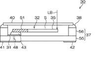
図1ないし図3は、本発明の圧電デバイスの実施形態を示しており、図1はその概略平面図、図2は図1のB−B線概略断面図、図3は図1のC−C線切断端面図である。
これらの図において、圧電デバイス30は、圧電振動子を構成した例を示しており、この圧電デバイス30は、図1および図2に示すように、パッケージ37内に圧電振動片32を収容している。パッケージ37は、図2に示すように、第1の基板55と第2の基板56とを積層して形成されており、例えば、絶縁材料として、酸化アルミニウム質のセラミックグリーンシートを成形して図示の形状とした後で、焼結して形成されている。
1 to 3 show an embodiment of a piezoelectric device of the present invention, FIG. 1 is a schematic plan view thereof, FIG. 2 is a schematic sectional view taken along line BB of FIG. 1, and FIG. It is a C-line cut end view.
In these drawings, the
パッケージ37は、図2に示すように、第2の基板56の内側の材料を除去することで、内部空間Sのスペースを形成している。この内部空間Sが圧電振動片32を収容するための収容空間である。そして、第1の基板55に形成した電極部31,31の上に、導電性接着剤43,43を用いて、圧電振動片32の基部に設けた引出し電極33a,34aの箇所を載置して接合している。なお、電極部31,31はパッケージ裏面の実装端子41,42と導電スルーホールなどで接続されている。パッケージ37は、圧電振動片32を収容した後で、透明なガラス製の蓋体40が封止材38を用いて接合されることにより、気密に封止されている。これにより、蓋体40を封止した後で、外部からレーザ光LBを照射して圧電振動片32の電極(図示せず)などをトリミングして、周波数調整できるようになっている。
As shown in FIG. 2, the
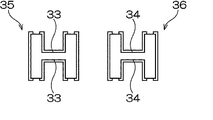
圧電振動片32は、例えば水晶で形成されており、水晶以外にもタンタル酸リチウム,ニオブ酸リチウム等の圧電材料を利用することができる。この圧電振動片32は、図1に示すように、パッケージ37側と固定される基部51と、この基部51を基端として、図において右に向けて、二股に別れて平行に延びる一対の振動腕35,36を備えている。
各振動腕35,36の主面には、好ましくは、それぞれ長さ方向に延びる長溝33,34を形成し、図3に示すように、この長溝内に励振用の電極が設けられている(符号省略)。このような圧電振動片32の音叉状の外形と、各振動腕に設ける長溝は、それぞれ例えば水晶ウエハなどの材料をフッ酸溶液などでウエットエッチングしたり、ドライエッチングすることにより精密に形成することができる。
The piezoelectric vibrating
The main surfaces of the vibrating
励振電極は、この長溝内と、各振動腕の側面とに形成され、各振動腕について長溝内の電極と、側面に設けた電極が対となるようにされ、各電極は、図1で説明した引出し電極33a,34aにそれぞれ引き回されている。これにより、圧電デバイス30を実装基板などに実装した場合に、外部からの駆動電圧が、各実装端子41,42から、電極部31,31を介して圧電振動片32の各引出し電極33a,34aに伝えられ、上記した各励振電極に伝えられるようになっている。
The excitation electrode is formed in the long groove and on the side surface of each vibrating arm, and for each vibrating arm, the electrode in the long groove and the electrode provided on the side surface are paired. Each electrode is described in FIG. The drawn
これにより、長溝33,34内の励振電極に駆動電圧が印加されることによって、駆動時に、各振動腕の長溝が形成された領域の内部の電界効率を高めることができるようになっている。長溝33,34が長い程、振動腕35,36を形成する材料について電界効率が向上し、振動腕の全長Lに対して、長溝33,34の基部51からの長さPLが、少なくともPL/L=0.7程度までは、長くするほど圧電振動片32のCI値は下がることがわかっている。
また、好ましくは、基部51には、この基部51の幅方向の寸法に関して部分的に縮幅して形成した凹部もしくは切り込み部44,44が形成されている。この切り込み部44,44は、基部51の各振動腕35,36の付け根に近接した箇所である。これにより、各振動腕35,36の屈曲振動による振動の基部51側への漏れ込みを大きく低減することができ、CI値の抑制効果を得ることができる。
Thereby, by applying a driving voltage to the excitation electrodes in the
Preferably, the
さらに、圧電振動片32においては、図1に示されている形状に各振動腕35,36が形成されている。各振動腕は同じ形状であるから、振動腕35について説明する。この実施形態では、基部51から延びる振動腕35の腕幅はW1で、その全長にわたって変化がない。
ところが、長溝33は、その基部51寄りの基端部で、溝幅MW1が小さく、先端にいくに従って溝幅MW2が次第に大きくなるようにされている。
Further, in the piezoelectric vibrating
However, the
これにより、振動腕35の根本部分が先端側と比較してその剛性を強化される。すなわち、振動腕35の長溝33において、溝幅が小さくされている符号MW1の箇所では、長溝33の両側の壁部(図3参照)の厚みが、振動腕35のより先端側の領域よりも厚くされることによって、剛性が強化されている。
このため、後述するように、2次の高調波における振動の際に大きく歪む位置を、振動腕35のより先端側に位置させることができると考えられ、このことにより、長溝33を長くして圧電材料の電界効率を上げて、基本波のCI値を低くしつつも、2次の高調波のCI値の低下を招くことがないようにすることができる。かくして、小型化しても、基本波のCI値を低く抑えることができる圧電振動片を提供することができる。
As a result, the rigidity of the root portion of the vibrating
For this reason, as will be described later, it is considered that a position that is greatly distorted at the time of vibration at the second harmonic can be positioned closer to the distal end side of the vibrating
この点について、さらに詳しく説明する。
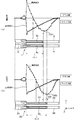
図4は、従来の圧電振動片1と、本実施形態の圧電振動片32について、駆動電圧を印加して屈曲振動させる場合、横軸に示した圧電振動片の長さ方向に関して、各部の歪み量を縦軸に示したグラフであり、図4(a)は従来の圧電振動片1、図4(b)は本実施形態の圧電振動片32を示し、Aは基本波による振動時の歪み量、Bは2次の高調波による振動時の歪み量をそれぞれ表している。なお、これらの図において、圧電振動片の基部の切り込み部または凹部は図が複雑になるので、記載を省略している。
This point will be described in more detail.
FIG. 4 shows the distortion of each part of the conventional piezoelectric vibrating
図4のグラフで示す歪み量に関して、基本波Aは、振動腕の先端になるに従い歪みは小さくなっていくが、高調波Bでは振動腕先端側に大きな歪みを持っているところがある。こうした歪み方の違いにより、励振電極を長くして行った時の基本波のCI値低下に比べ高調波のCI値低下は大きくなる。 また、図4(a)の従来の圧電振動片1においては、長溝3a,4aの長さPL1は、図9の振動腕の全長lを1としたとき、例えば0.5程度になるようにされている。これに対して、図4(b)の本実施形態の圧電振動片32では、長溝33,34の長さPL2は、図1の振動腕の全長Lを1としたとき、たとえば0.6程度としている。これによって、CI値が抑制されるようになっている。
Regarding the distortion amount shown in the graph of FIG. 4, the distortion of the fundamental wave A becomes smaller as it reaches the tip of the vibrating arm, but the harmonic B has a large distortion on the tip side of the vibrating arm. Due to the difference in the distortion method, the reduction in the CI value of the harmonics becomes larger than the reduction in the CI value of the fundamental wave when the excitation electrode is made longer. Further, in the conventional piezoelectric vibrating
ここで、圧電振動片の振動腕に関して、従来と同じ構造を採用すると、形成されている励振電極位置における2次高調波Bのマイナス歪み量が急激に増大する。
そうすると、基本波のCI値を低くできたとしても、2次の高調波のCI値はさらに低くなり、高調波のCI値/基本波のCI値であるCI値比が小さくなり、「1」を下回る。そうなると基本波ではなく高調波での発振の可能性がでてくる。
Here, if the same structure as the conventional structure is adopted for the vibrating arm of the piezoelectric vibrating piece, the amount of negative distortion of the second-order harmonic B at the position of the excitation electrode formed increases abruptly.
Then, even if the CI value of the fundamental wave can be lowered, the CI value of the second harmonic becomes further lower, and the CI value ratio that is the CI value of the harmonic / the CI value of the fundamental wave becomes small. Below. Then, there is a possibility of oscillation with harmonics instead of fundamental waves.
そこで、長溝33について、図1で説明したように、その基部51寄りの基端部で、溝幅MW1が小さく、先端にいくに従って溝幅MW2が次第に大きくなるようにしたことで、図4(a)と、図4(b)とを比較して理解されるように、2次の高調波の歪み量Bにおけるマイナス方向のピーク位置が、符号CM1と符号CM2とでそれぞれ示すように、距離MBで示す分だけ、圧電振動片の振動腕の長さ方向(図示のY方向)に沿って、先端側に移動する。
Therefore, as described in FIG. 1, the groove width MW1 is small at the base end portion near the
このことにより、形成されている励振電極位置における2次高調波Bのマイナス歪み量は低く抑えることができるようになる。こうして、基本波のCI値を低くしつつも、高調波のCI値の低下は抑えられることになる。 図5は、本実施形態の圧電振動片32についてのドライブ特性を示すグラフであり、図の横軸に沿って、駆動電圧のレベルを徐々に増大させると、縦軸の周波数変化がプラス方向に生じている。このことは、図10で説明したZ方向振動の成分を抑制でき、エネルギーロスが僅かであって、CI値が抑制できることを示している。
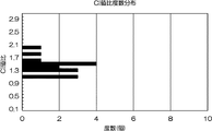
また、図6は、圧電振動片32のCI値比(高調波のCI値/基本波のCI値)を示しており、CI値比は全体として1よりも大きい。
かくして、圧電振動片32では、各振動腕35,36の電界効率を向上させて、CI値を低くすることができ、しかも2次の高調波のCI値は低くならないので、基本波での良好な振動特性を維持できる。
As a result, the amount of negative distortion of the second harmonic B at the position of the excitation electrode formed can be kept low. In this way, it is possible to suppress a decrease in the harmonic CI value while lowering the CI value of the fundamental wave. FIG. 5 is a graph showing the drive characteristics of the piezoelectric vibrating
FIG. 6 shows the CI value ratio of the piezoelectric vibrating piece 32 (CI value of harmonic / CI value of fundamental wave), and the CI value ratio is larger than 1 as a whole.
Thus, in the piezoelectric vibrating
図7は、圧電振動片の変形例1を示す概略平面図であり、図1の圧電振動片32と同じ符号を付した箇所は共通する構成であるから、重複した説明は省略し、以下、相違点を中心に説明する。
圧電振動片60の各振動腕35,36の長溝33,34には、溝幅の方向に設けたリブ状もしくは壁状の補強部61が形成されている。各振動腕35,36は同じ構造であるから、振動腕36についてだけ説明すると、補強部61は、複数個が、長溝34の長さ方向にY沿って複数設けられている。
FIG. 7 is a schematic plan view showing Modification Example 1 of the piezoelectric vibrating piece, and the portions denoted by the same reference numerals as those of the piezoelectric vibrating
Rib-shaped or wall-shaped reinforcing
そして、これら複数の補強部61,61,61は、長溝の長さ方向に沿って、先端側にいく程、その間隔t1,t2,t3が次第に大きな間隔となるように設けられている。
このように、長溝34に設けた各補強部61,61,61が、長溝の長さ方向に沿って、先端側にいく程大きな間隔をおいて形成されているので、基部51側で振動腕36の剛性が高く、先端側にいくにしたがい剛性が低下する構造とされている。
これによって、上述の実施形態と同様、図4で説明したように、2次の高調波の歪み量Bにおけるマイナス方向のピーク位置が、符号CM1と符号CM2とでそれぞれ示すように、距離MBで示す分だけ、圧電振動片60の振動腕36の長さ方向(Y方向)に沿って、先端側に移動されているので、第1の実施形態と同様の作用効果を発揮することができる。
And these some
In this way, the reinforcing
Accordingly, as described in FIG. 4, the peak positions in the negative direction of the second-order harmonic distortion amount B are represented by the distance MB as indicated by the reference symbols CM1 and CM2, as described in FIG. Since it is moved to the tip side along the length direction (Y direction) of the vibrating
図8は、圧電振動片の変形例2を示す概略平面図であり、図1の圧電振動片32と同じ符号を付した箇所は共通する構成であるから、重複した説明は省略し、以下、相違点を中心に説明する。
変形例2の圧電振動片70においては、各振動腕35,36が、先端にいくに従って徐々に腕幅が小さくなるように構成されている。各振動腕35,36は同じ構造であるから、振動腕36についてだけ説明すると、振動腕36の基端部側の腕幅W3は、先端側の腕幅W2よりも大きく、腕幅は、基端部から先端側にいくに従って、徐々に小さくなるようにされている。
これにより、基部51側で振動腕36の剛性が高く、先端側にいくにしたがい剛性が低下する構造とされている。
FIG. 8 is a schematic plan view showing Modification Example 2 of the piezoelectric vibrating piece, and the portions denoted by the same reference numerals as those of the piezoelectric vibrating
In the piezoelectric vibrating
Thereby, the rigidity of the vibrating
さらに好ましくは、長溝34に関して、その基部51寄りの領域である領域Rtの箇所において、溝幅が小さく形成されている。
このため、長溝34の領域Rtに関しては、溝をはさむ両側の壁部の厚みが大きいことから、振動腕36の基部51に近接した領域の剛性は、その領域より先端側と比べると、より高い剛性となるようにされている。
これによって、上述の実施形態と同様、図4で説明したように、2次の高調波の歪み量Bにおけるマイナス方向のピーク位置が、符号CM1と符号CM2とでそれぞれ示すように、距離MBで示す分だけ、圧電振動片70の振動腕36の長さ方向(Y方向)に沿って、先端側に移動されているので、第1の実施形態と同様の作用効果を発揮することができる。
More preferably, with respect to the
For this reason, with respect to the region Rt of the
Accordingly, as described in FIG. 4, the peak positions in the negative direction of the second-order harmonic distortion amount B are represented by the distance MB as indicated by the reference symbols CM1 and CM2, as described in FIG. Since it is moved to the tip side along the length direction (Y direction) of the vibrating
本発明は上述の実施形態に限定されない。所謂音叉型の圧電振動片において、その振動腕の根本付近の剛性が高くされる構成を備えていれば、上述の実施形態や変形例以外の構造を備えるものも本発明の範囲である。
また、各実施形態の各構成はこれらを適宜組み合わせたり、省略し、図示しない他の構成と組み合わせることができる。
また、この発明は、箱状のパッケージに圧電振動片を収容したものに限らず、シリンダー状の容器に圧電振動片を収容したもの、圧電振動片をジャイロセンサとして機能するようにしたもの、さらには、圧電振動子、圧電発振器等の名称にかかわらず、圧電振動片を利用したあらゆる圧電デバイスに適用することができる。
The present invention is not limited to the above-described embodiment. A so-called tuning-fork type piezoelectric vibrating piece is within the scope of the present invention if it has a configuration in which the rigidity near the root of the vibrating arm is increased.
In addition, each configuration of each embodiment can be appropriately combined or omitted, and can be combined with other configurations not shown.
The present invention is not limited to the case where the piezoelectric vibrating piece is accommodated in the box-shaped package, the case where the piezoelectric vibrating piece is accommodated in the cylindrical container, the piezoelectric vibrating piece functioning as a gyro sensor, Can be applied to any piezoelectric device using a piezoelectric vibrating piece regardless of the name of a piezoelectric vibrator, a piezoelectric oscillator, or the like.
30・・・圧電デバイス、32,60,70・・・圧電振動片、33,34・・・長溝、35,36・・・振動腕。 30 ... Piezoelectric device, 32, 60, 70 ... Piezoelectric vibrating piece, 33, 34 ... Long groove, 35, 36 ... Vibrating arm.
Claims (6)
前記基部と一体に形成され、互いに平行に延びる複数の振動腕と
前記各振動腕の長手方向に沿って形成された長溝と、
前記長溝に形成した励振用の電極と
を備えており、
前記各振動腕が、前記長溝が形成された領域において、前記基部側から先端側にいくに従って剛性が低下する構成とされていて、
前記長溝には、溝幅の方向に設けたリブ状もしくは壁状の補強部が、長溝の長さ方向に沿って複数設けられており、前記複数の補強部が、長溝の長さ方向に沿って、先端側にいく程大きな間隔をおいて形成されている
ことを特徴とする、圧電振動片。 A base formed of piezoelectric material;
A plurality of vibrating arms formed integrally with the base and extending in parallel with each other; and a long groove formed along the longitudinal direction of each vibrating arm;
An excitation electrode formed in the long groove, and
Each of the vibrating arms is configured such that in the region where the long groove is formed, the rigidity decreases as going from the base side to the tip side,
The long groove is provided with a plurality of rib-like or wall-like reinforcing portions provided in the groove width direction along the length direction of the long groove, and the plurality of reinforcing portions are provided along the length direction of the long groove. The piezoelectric vibrating piece is formed with a larger distance toward the tip side .
前記圧電振動片が、
圧電材料により形成された基部と、
前記基部と一体に形成され、互いに平行に延びる複数の振動腕と
前記各振動腕の長手方向に沿って形成された長溝と、
前記長溝に形成した励振用の電極と
を備えており、
前記各振動腕が、前記長溝が形成された領域において、前記基部側から先端側にいくに従って剛性が低下する構成とされていて、
前記長溝には、溝幅の方向に設けたリブ状もしくは壁状の補強部が、長溝の長さ方向に沿って複数設けられており、前記複数の補強部が、長溝の長さ方向に沿って、先端側にいく程大きな間隔をおいて形成されている
ことを特徴とする、圧電デバイス。 A piezoelectric device containing a piezoelectric vibrating piece in a package or case,
The piezoelectric vibrating piece is
A base formed of piezoelectric material;
A plurality of vibrating arms formed integrally with the base and extending in parallel with each other; and a long groove formed along the longitudinal direction of each vibrating arm;
An excitation electrode formed in the long groove, and
Each of the vibrating arms is configured such that in the region where the long groove is formed, the rigidity decreases as going from the base side to the tip side,
The long groove is provided with a plurality of rib-like or wall-like reinforcing portions provided in the groove width direction along the length direction of the long groove, and the plurality of reinforcing portions are provided along the length direction of the long groove. The piezoelectric device is characterized in that the piezoelectric device is formed with a larger distance toward the tip side .
Priority Applications (1)
| Application Number | Priority Date | Filing Date | Title |
|---|---|---|---|
| JP2004157710A JP4465710B2 (en) | 2004-05-27 | 2004-05-27 | Piezoelectric vibrating piece and piezoelectric device |
Applications Claiming Priority (1)
| Application Number | Priority Date | Filing Date | Title |
|---|---|---|---|
| JP2004157710A JP4465710B2 (en) | 2004-05-27 | 2004-05-27 | Piezoelectric vibrating piece and piezoelectric device |
Related Child Applications (1)
| Application Number | Title | Priority Date | Filing Date |
|---|---|---|---|
| JP2009298771A Division JP5182281B2 (en) | 2009-12-28 | 2009-12-28 | Vibrating piece and device |
Publications (3)
| Publication Number | Publication Date |
|---|---|
| JP2005341251A JP2005341251A (en) | 2005-12-08 |
| JP2005341251A5 JP2005341251A5 (en) | 2007-07-05 |
| JP4465710B2 true JP4465710B2 (en) | 2010-05-19 |
Family
ID=35494299
Family Applications (1)
| Application Number | Title | Priority Date | Filing Date |
|---|---|---|---|
| JP2004157710A Expired - Fee Related JP4465710B2 (en) | 2004-05-27 | 2004-05-27 | Piezoelectric vibrating piece and piezoelectric device |
Country Status (1)
| Country | Link |
|---|---|
| JP (1) | JP4465710B2 (en) |
Families Citing this family (14)
| Publication number | Priority date | Publication date | Assignee | Title |
|---|---|---|---|---|
| JP4839800B2 (en) | 2005-11-25 | 2011-12-21 | パナソニック電工株式会社 | Ultrasonic hair set |
| JP2007274610A (en) * | 2006-03-31 | 2007-10-18 | Nippon Dempa Kogyo Co Ltd | Quartz-crystal vibrator, and package thereof |
| JP5155275B2 (en) | 2008-10-16 | 2013-03-06 | 日本電波工業株式会社 | Tuning fork type piezoelectric vibrating piece, piezoelectric frame and piezoelectric device |
| JP5130502B2 (en) * | 2009-06-25 | 2013-01-30 | 有限会社ピエデック技術研究所 | Piezoelectric vibrator and piezoelectric oscillator |
| JP5565154B2 (en) | 2009-09-11 | 2014-08-06 | セイコーエプソン株式会社 | Vibrating piece, vibrator, oscillator, and electronic device |
| JP5057122B2 (en) * | 2010-06-25 | 2012-10-24 | セイコーエプソン株式会社 | Piezoelectric vibrating piece and piezoelectric vibrator |
| JP2012039509A (en) * | 2010-08-10 | 2012-02-23 | Seiko Instruments Inc | Piezoelectric vibrating piece, piezoelectric resonator, oscillator, electronic device, and radio-controlled timepiece |
| JP5592812B2 (en) * | 2011-01-27 | 2014-09-17 | エスアイアイ・クリスタルテクノロジー株式会社 | Piezoelectric vibrating piece, piezoelectric vibrator, oscillator, electronic device, and radio clock |
| JP5819151B2 (en) * | 2011-09-28 | 2015-11-18 | エスアイアイ・クリスタルテクノロジー株式会社 | Piezoelectric vibrator, piezoelectric vibrator, oscillator, electronic device and radio clock |
| JPWO2014002892A1 (en) * | 2012-06-27 | 2016-05-30 | 株式会社村田製作所 | Tuning fork crystal unit |
| JP5526312B2 (en) * | 2012-10-03 | 2014-06-18 | 有限会社ピエデック技術研究所 | Piezoelectric vibrator, piezoelectric unit, piezoelectric oscillator and electronic equipment |
| JP5762608B2 (en) * | 2014-07-31 | 2015-08-12 | エスアイアイ・クリスタルテクノロジー株式会社 | Piezoelectric vibrating piece, piezoelectric vibrator, oscillator, electronic device, and radio clock |
| JP6587389B2 (en) * | 2015-01-20 | 2019-10-09 | エスアイアイ・クリスタルテクノロジー株式会社 | Piezoelectric vibrating piece and piezoelectric vibrator |
| JP6987623B2 (en) * | 2017-11-27 | 2022-01-05 | 京セラ株式会社 | Piezoelectric element, piezoelectric device and method of manufacturing piezoelectric element |
-
2004
- 2004-05-27 JP JP2004157710A patent/JP4465710B2/en not_active Expired - Fee Related
Also Published As
| Publication number | Publication date |
|---|---|
| JP2005341251A (en) | 2005-12-08 |
Similar Documents
| Publication | Publication Date | Title |
|---|---|---|
| JP4548148B2 (en) | Piezoelectric vibrating piece and piezoelectric device | |
| JP4415389B2 (en) | Piezoelectric device | |
| JP4442521B2 (en) | Piezoelectric vibrating piece and piezoelectric device | |
| JP4301200B2 (en) | Piezoelectric vibrating piece and piezoelectric device | |
| KR100712758B1 (en) | Piezoelectric resonator element and piezoelectric device | |
| JP4207873B2 (en) | Piezoelectric vibrating piece and piezoelectric device | |
| JP4465710B2 (en) | Piezoelectric vibrating piece and piezoelectric device | |
| JP4301201B2 (en) | Piezoelectric oscillator | |
| JP2007096900A (en) | Piezoelectric vibrating piece and piezoelectric device | |
| JP2006352771A (en) | Piezoelectric oscillating piece, piezoelectric device, electronic equipment and portable telephone set | |
| JP4985960B2 (en) | Vibrating piece and vibrator | |
| JP4265499B2 (en) | Piezoelectric vibrating piece and piezoelectric device | |
| JP2008048274A (en) | Piezo-electric vibrating piece and piezo-electric device | |
| JP2011166325A (en) | Tuning fork type piezoelectric vibration piece and piezoelectric device | |
| JP4784168B2 (en) | Piezoelectric vibrating piece and piezoelectric device | |
| JP2008022413A (en) | Piezoelectric vibration chip and piezoelectric device | |
| JP5182281B2 (en) | Vibrating piece and device | |
| JP5370471B2 (en) | Vibrating piece and device | |
| JP5533984B2 (en) | Vibrating piece, vibrator, oscillator, sensor and device | |
| JP5565448B2 (en) | Vibrating piece, vibrator, oscillator, sensor and device | |
| JP4301140B2 (en) | Piezoelectric vibrating piece and piezoelectric device | |
| JP5761399B2 (en) | Vibrating piece, vibrator, oscillator, sensor and device | |
| JP4222288B2 (en) | Piezoelectric vibrating piece and piezoelectric device | |
| JP2005123828A (en) | Tuning-fork piezo-electric oscillation piece and piezo-electric device | |
| JP2015149751A (en) | Piezoelectric vibration piece and piezoelectric device |
Legal Events
| Date | Code | Title | Description |
|---|---|---|---|
| A521 | Written amendment |
Free format text: JAPANESE INTERMEDIATE CODE: A523 Effective date: 20070523 |
|
| A621 | Written request for application examination |
Free format text: JAPANESE INTERMEDIATE CODE: A621 Effective date: 20070523 |
|
| A131 | Notification of reasons for refusal |
Free format text: JAPANESE INTERMEDIATE CODE: A131 Effective date: 20091102 |
|
| A521 | Written amendment |
Free format text: JAPANESE INTERMEDIATE CODE: A523 Effective date: 20091228 |
|
| TRDD | Decision of grant or rejection written | ||
| A01 | Written decision to grant a patent or to grant a registration (utility model) |
Free format text: JAPANESE INTERMEDIATE CODE: A01 Effective date: 20100201 |
|
| A01 | Written decision to grant a patent or to grant a registration (utility model) |
Free format text: JAPANESE INTERMEDIATE CODE: A01 |
|
| A61 | First payment of annual fees (during grant procedure) |
Free format text: JAPANESE INTERMEDIATE CODE: A61 Effective date: 20100214 |
|
| R150 | Certificate of patent or registration of utility model |
Free format text: JAPANESE INTERMEDIATE CODE: R150 |
|
| FPAY | Renewal fee payment (event date is renewal date of database) |
Free format text: PAYMENT UNTIL: 20130305 Year of fee payment: 3 |
|
| FPAY | Renewal fee payment (event date is renewal date of database) |
Free format text: PAYMENT UNTIL: 20140305 Year of fee payment: 4 |
|
| LAPS | Cancellation because of no payment of annual fees |