JP4464796B2 - Heat exchanger and manufacturing method thereof - Google Patents
Heat exchanger and manufacturing method thereof Download PDFInfo
- Publication number
- JP4464796B2 JP4464796B2 JP2004329987A JP2004329987A JP4464796B2 JP 4464796 B2 JP4464796 B2 JP 4464796B2 JP 2004329987 A JP2004329987 A JP 2004329987A JP 2004329987 A JP2004329987 A JP 2004329987A JP 4464796 B2 JP4464796 B2 JP 4464796B2
- Authority
- JP
- Japan
- Prior art keywords
- heat exchanger
- hydrophilic layer
- antibacterial material
- deodorizing antibacterial
- protective layer
- Prior art date
- Legal status (The legal status is an assumption and is not a legal conclusion. Google has not performed a legal analysis and makes no representation as to the accuracy of the status listed.)
- Expired - Fee Related
Links
- 238000004519 manufacturing process Methods 0.000 title claims description 18
- 239000000463 material Substances 0.000 claims description 104
- 239000010410 layer Substances 0.000 claims description 95
- 230000001877 deodorizing effect Effects 0.000 claims description 85
- 230000000844 anti-bacterial effect Effects 0.000 claims description 77
- 229910052782 aluminium Inorganic materials 0.000 claims description 65
- XAGFODPZIPBFFR-UHFFFAOYSA-N aluminium Chemical compound [Al] XAGFODPZIPBFFR-UHFFFAOYSA-N 0.000 claims description 65
- 239000011241 protective layer Substances 0.000 claims description 50
- RYGMFSIKBFXOCR-UHFFFAOYSA-N Copper Chemical compound [Cu] RYGMFSIKBFXOCR-UHFFFAOYSA-N 0.000 claims description 31
- 229910052802 copper Inorganic materials 0.000 claims description 31
- 239000010949 copper Substances 0.000 claims description 31
- GWEVSGVZZGPLCZ-UHFFFAOYSA-N Titan oxide Chemical compound O=[Ti]=O GWEVSGVZZGPLCZ-UHFFFAOYSA-N 0.000 claims description 26
- OGIDPMRJRNCKJF-UHFFFAOYSA-N titanium oxide Inorganic materials [Ti]=O OGIDPMRJRNCKJF-UHFFFAOYSA-N 0.000 claims description 25
- XLYOFNOQVPJJNP-UHFFFAOYSA-N water Substances O XLYOFNOQVPJJNP-UHFFFAOYSA-N 0.000 claims description 14
- HCHKCACWOHOZIP-UHFFFAOYSA-N Zinc Chemical compound [Zn] HCHKCACWOHOZIP-UHFFFAOYSA-N 0.000 claims description 13
- 239000000243 solution Substances 0.000 claims description 13
- 229910052725 zinc Inorganic materials 0.000 claims description 13
- 239000011701 zinc Substances 0.000 claims description 13
- 239000002245 particle Substances 0.000 claims description 12
- 239000002105 nanoparticle Substances 0.000 claims description 10
- 239000007864 aqueous solution Substances 0.000 claims description 7
- 239000002202 Polyethylene glycol Substances 0.000 claims description 5
- 239000000203 mixture Substances 0.000 claims description 5
- 229920001223 polyethylene glycol Polymers 0.000 claims description 5
- 239000007788 liquid Substances 0.000 claims description 3
- 238000010304 firing Methods 0.000 claims description 2
- 239000002994 raw material Substances 0.000 claims description 2
- 230000000845 anti-microbial effect Effects 0.000 claims 1
- 239000002781 deodorant agent Substances 0.000 claims 1
- QGZKDVFQNNGYKY-UHFFFAOYSA-N Ammonia Chemical compound N QGZKDVFQNNGYKY-UHFFFAOYSA-N 0.000 description 26
- 229910021529 ammonia Inorganic materials 0.000 description 13
- 239000003054 catalyst Substances 0.000 description 8
- 238000009833 condensation Methods 0.000 description 7
- 230000005494 condensation Effects 0.000 description 7
- 238000005260 corrosion Methods 0.000 description 6
- 230000007797 corrosion Effects 0.000 description 6
- 238000004332 deodorization Methods 0.000 description 6
- 238000000034 method Methods 0.000 description 6
- 239000011259 mixed solution Substances 0.000 description 6
- 239000011941 photocatalyst Substances 0.000 description 5
- 239000003507 refrigerant Substances 0.000 description 5
- 238000009423 ventilation Methods 0.000 description 5
- 238000001816 cooling Methods 0.000 description 3
- 230000001678 irradiating effect Effects 0.000 description 3
- 230000001699 photocatalysis Effects 0.000 description 3
- 238000011045 prefiltration Methods 0.000 description 3
- 239000000126 substance Substances 0.000 description 3
- CURLTUGMZLYLDI-UHFFFAOYSA-N Carbon dioxide Chemical compound O=C=O CURLTUGMZLYLDI-UHFFFAOYSA-N 0.000 description 2
- XLOMVQKBTHCTTD-UHFFFAOYSA-N Zinc monoxide Chemical compound [Zn]=O XLOMVQKBTHCTTD-UHFFFAOYSA-N 0.000 description 2
- 230000003197 catalytic effect Effects 0.000 description 2
- 239000000084 colloidal system Substances 0.000 description 2
- 239000002826 coolant Substances 0.000 description 2
- 238000010586 diagram Methods 0.000 description 2
- 238000007598 dipping method Methods 0.000 description 2
- 238000010438 heat treatment Methods 0.000 description 2
- 238000003754 machining Methods 0.000 description 2
- 229910052751 metal Inorganic materials 0.000 description 2
- 239000002184 metal Substances 0.000 description 2
- 239000000843 powder Substances 0.000 description 2
- 230000008569 process Effects 0.000 description 2
- 229910052709 silver Inorganic materials 0.000 description 2
- 239000004332 silver Substances 0.000 description 2
- 238000005245 sintering Methods 0.000 description 2
- 241000894006 Bacteria Species 0.000 description 1
- JPVYNHNXODAKFH-UHFFFAOYSA-N Cu2+ Chemical compound [Cu+2] JPVYNHNXODAKFH-UHFFFAOYSA-N 0.000 description 1
- 229910000831 Steel Inorganic materials 0.000 description 1
- PTFCDOFLOPIGGS-UHFFFAOYSA-N Zinc dication Chemical compound [Zn+2] PTFCDOFLOPIGGS-UHFFFAOYSA-N 0.000 description 1
- 238000004378 air conditioning Methods 0.000 description 1
- 239000011230 binding agent Substances 0.000 description 1
- 238000007664 blowing Methods 0.000 description 1
- 229910002092 carbon dioxide Inorganic materials 0.000 description 1
- 239000001569 carbon dioxide Substances 0.000 description 1
- 230000008859 change Effects 0.000 description 1
- 238000004140 cleaning Methods 0.000 description 1
- 230000001143 conditioned effect Effects 0.000 description 1
- 229910001431 copper ion Inorganic materials 0.000 description 1
- 239000002537 cosmetic Substances 0.000 description 1
- 238000007865 diluting Methods 0.000 description 1
- 239000000428 dust Substances 0.000 description 1
- 239000010954 inorganic particle Substances 0.000 description 1
- 238000000465 moulding Methods 0.000 description 1
- 239000005416 organic matter Substances 0.000 description 1
- 230000001590 oxidative effect Effects 0.000 description 1
- 238000004080 punching Methods 0.000 description 1
- 239000010959 steel Substances 0.000 description 1
- 230000007704 transition Effects 0.000 description 1
- 239000011787 zinc oxide Substances 0.000 description 1
Images


Classifications
-
- F—MECHANICAL ENGINEERING; LIGHTING; HEATING; WEAPONS; BLASTING
- F28—HEAT EXCHANGE IN GENERAL
- F28F—DETAILS OF HEAT-EXCHANGE AND HEAT-TRANSFER APPARATUS, OF GENERAL APPLICATION
- F28F19/00—Preventing the formation of deposits or corrosion, e.g. by using filters or scrapers
- F28F19/02—Preventing the formation of deposits or corrosion, e.g. by using filters or scrapers by using coatings, e.g. vitreous or enamel coatings
-
- F—MECHANICAL ENGINEERING; LIGHTING; HEATING; WEAPONS; BLASTING
- F28—HEAT EXCHANGE IN GENERAL
- F28F—DETAILS OF HEAT-EXCHANGE AND HEAT-TRANSFER APPARATUS, OF GENERAL APPLICATION
- F28F13/00—Arrangements for modifying heat-transfer, e.g. increasing, decreasing
- F28F13/18—Arrangements for modifying heat-transfer, e.g. increasing, decreasing by applying coatings, e.g. radiation-absorbing, radiation-reflecting; by surface treatment, e.g. polishing
-
- F—MECHANICAL ENGINEERING; LIGHTING; HEATING; WEAPONS; BLASTING
- F28—HEAT EXCHANGE IN GENERAL
- F28F—DETAILS OF HEAT-EXCHANGE AND HEAT-TRANSFER APPARATUS, OF GENERAL APPLICATION
- F28F21/00—Constructions of heat-exchange apparatus characterised by the selection of particular materials
- F28F21/08—Constructions of heat-exchange apparatus characterised by the selection of particular materials of metal
- F28F21/081—Heat exchange elements made from metals or metal alloys
- F28F21/084—Heat exchange elements made from metals or metal alloys from aluminium or aluminium alloys
-
- F—MECHANICAL ENGINEERING; LIGHTING; HEATING; WEAPONS; BLASTING
- F28—HEAT EXCHANGE IN GENERAL
- F28F—DETAILS OF HEAT-EXCHANGE AND HEAT-TRANSFER APPARATUS, OF GENERAL APPLICATION
- F28F2245/00—Coatings; Surface treatments
- F28F2245/02—Coatings; Surface treatments hydrophilic
Description
本発明は、熱交換器及びその製造方法に係り、特にエアコン、冷蔵庫、除湿機、自動車等の機器に用いられるアルミフィンを有する熱交換器及びその製造方法に好適なものである。 The present invention relates to a heat exchanger and a method for manufacturing the same, and is particularly suitable for a heat exchanger having aluminum fins used in devices such as an air conditioner, a refrigerator, a dehumidifier, and an automobile, and a method for manufacturing the same.
エアコン、冷蔵庫等に用いられる一般的な熱交換器は、内部に冷媒を流す銅パイプと、表面に親水層を有するアルミフィンとを組み合わせて構成されている。かかる熱交換器において、粒子径が数μmの粉末の非溶出型の酸化チタンを親水層に添加し、400nm以下の波長の紫外線を照射することにより酸化チタンを励起して臭気成分を酸化分解する光触媒機能を持たせるようにすることが考えられている。この酸化チタンを添加した親水層は銅パイプとアルミフィンとを組み合わせた後にディッピングなどにより形成されている。さらには、光触媒機能を持たせた熱交換器において、酸化チタンに銀を担持させて抗菌性能を向上することも考えられている。 A general heat exchanger used in an air conditioner, a refrigerator, or the like is configured by combining a copper pipe for flowing a refrigerant therein and an aluminum fin having a hydrophilic layer on the surface. In such a heat exchanger, powdered non-eluting titanium oxide having a particle size of several μm is added to the hydrophilic layer, and the titanium oxide is excited by irradiating ultraviolet rays having a wavelength of 400 nm or less to oxidize and decompose odor components. It is considered to have a photocatalytic function. The hydrophilic layer to which titanium oxide is added is formed by dipping or the like after combining a copper pipe and an aluminum fin. Furthermore, in a heat exchanger having a photocatalytic function, it is also considered that silver is supported on titanium oxide to improve antibacterial performance.
なお、従来技術に関連する特許文献としては、特開平8−296992号公報(特許文献1)及び特開2001−201288号公報(特許文献2)が挙げられる。 Patent documents related to the prior art include JP-A-8-269992 (Patent Document 1) and JP-A-2001-201288 (Patent Document 2).
しかし、従来の熱交換器では、光触媒として用いる酸化チタンは粒子径が数μmの粉末で非溶出型であるため、光触媒粒子を親水層の表面に多く露出させることが難しく、しかも親水層を厚くして光触媒のバインダーとする必要があった。このため、例えば特許文献1にも示されているように、エアコン内部に熱交換器に紫外線を照射するライトを設けたり、ライトの代わりに室内光を取入れて熱交換器に照射するための光透過窓を設けたりして、光を強く熱交換器に照射しないと十分な脱臭性能を得ることができず、しかも、厚い親水層による熱交換性能の低下を招いていた。 However, in conventional heat exchangers, titanium oxide used as a photocatalyst is a powder with a particle size of several μm and is non-eluting, so it is difficult to expose many photocatalyst particles on the surface of the hydrophilic layer, and the hydrophilic layer is thick. Therefore, it was necessary to use it as a binder for the photocatalyst. For this reason, for example, as disclosed in Patent Document 1, a light for irradiating the heat exchanger with ultraviolet rays is provided inside the air conditioner, or light for taking in indoor light instead of the light and irradiating the heat exchanger. A sufficient deodorizing performance cannot be obtained unless a transmissive window is provided to irradiate the heat exchanger strongly with light, and the heat exchange performance is reduced due to the thick hydrophilic layer.
また、親水層に数μmの無機粒子である光触媒が存在することになるため、親水層のアルミフィンへの密着性の低下を招くと共に、親水層の本来の機能である親水性の低下を招き、信頼性や熱交換性能が低下してしまうという問題が発生していた。 In addition, since the photocatalyst that is an inorganic particle of several μm exists in the hydrophilic layer, the adhesion of the hydrophilic layer to the aluminum fins is reduced, and the hydrophilicity that is the original function of the hydrophilic layer is also reduced. There has been a problem that reliability and heat exchange performance deteriorate.
さらには、エアコンの熱交換器においては、熱交換器が完成するまでの保護を目的として、アルミフィンの親水層の上に保護層を形成している。この保護層は、例えばエアコンに組み込んで運転したときに熱交換器表面に生成される結露水で洗い流されるものである。従来、この親水層と保護層は、混合液でフィン表面に塗布され、焼結の際に保護層の成分が表面側に溶出され、その結果として2層となるように製造されている。しかし、粒子径が数μmの粉末で非溶出型の酸化チタンを添加しているため、従来の混合液による製造方法では、酸化チタンが親水層と保護層に均等に分散され、親水層の方にのみ多くの酸化チタンを添加することはできない。このため、親水層の方にのみ多くの酸化チタンを添加するには、親水層に酸化チタンを多く添加して形成した後に、さらに保護層を形成するようにしなければならず、工程が増えてコストアップを招いてしまうという問題が発生していた。 Furthermore, in the heat exchanger of an air conditioner, a protective layer is formed on the hydrophilic layer of the aluminum fin for the purpose of protection until the heat exchanger is completed. This protective layer is washed away with dew condensation water generated on the surface of the heat exchanger when it is operated by being incorporated in an air conditioner, for example. Conventionally, the hydrophilic layer and the protective layer are applied to the fin surface with a mixed solution, and the components of the protective layer are eluted to the surface side during sintering, and as a result, the two layers are manufactured. However, since non-eluting titanium oxide is added in a powder with a particle size of several μm, titanium oxide is evenly dispersed in the hydrophilic layer and the protective layer in the conventional mixed liquid manufacturing method. It is not possible to add a large amount of titanium oxide alone. For this reason, in order to add a large amount of titanium oxide only to the hydrophilic layer, it is necessary to form a protective layer after adding a large amount of titanium oxide to the hydrophilic layer, which increases the number of processes. There has been a problem of increasing costs.
さらには、従来の熱交換器において、脱臭機能を有しない一般的な親水層を形成する場合には、親水層を予め形成したアルミフィンと銅パイプとを組み合わせることにより、生産性の高いものとしている。しかし、粒子径が数μmの酸化チタンを添加した親水層を予め形成したアルミフィンでは、アルミフィンに銅パイプを通すための穴等を加工する際に、この酸化チタンにより加工金型が直ぐに磨耗してしまう。このため、銅パイプとアルミフィンとを組み合わせた後に、親水層をディッピングなどにより形成しなければならず、生産性の低下を招くという問題が発生していた。 Furthermore, in the case of forming a general hydrophilic layer that does not have a deodorizing function in a conventional heat exchanger, a combination of aluminum fins previously formed with a hydrophilic layer and a copper pipe is considered to be highly productive. Yes. However, with aluminum fins that have been previously formed with a hydrophilic layer to which titanium oxide with a particle size of several μm is added, when machining holes for passing copper pipes through the aluminum fins, the machining die is immediately worn by this titanium oxide. Resulting in. For this reason, after combining a copper pipe and an aluminum fin, the hydrophilic layer has to be formed by dipping or the like, which causes a problem of reducing productivity.
さらには、銅パイプよりもイオン化傾向の小さい金属である銀を酸化チタンに担持して光触媒機能を向上しようとすると、熱交換器に結露水が発生したときに、局部電流腐食が起こり、銅パイプから銅イオンが溶出され腐食してしまうという問題が発生していた。 In addition, when silver, which is a metal that has a lower ionization tendency than copper pipes, is supported on titanium oxide to improve the photocatalytic function, local water corrosion occurs when condensed water is generated in the heat exchanger, and the copper pipes. There was a problem that copper ions were eluted from the steel and corroded.
本発明の目的は、安価に、結露による局部電流腐食を防止できると共に親水層の密着性及び親水性を良好なものとしつつ、僅かな光で十分な脱臭性能を得ることができる熱交換器及びその製造方法を提供することにある。 An object of the present invention is to provide a heat exchanger that can prevent local current corrosion due to condensation at a low cost and can obtain sufficient deodorizing performance with little light while improving the adhesion and hydrophilicity of the hydrophilic layer, and It is in providing the manufacturing method.
前記目的を達成するために、本発明は、内部に冷媒を流す銅パイプと、多数枚並べて前記銅パイプを貫通させ且つアルミ素材の上に親水層を形成し、前記親水層の表面上に結露水で洗い流される保護層を形成したアルミフィンとを備えた熱交換器において、前記親水層及び前記保護層は酸化チタンに亜鉛を担持させたナノ粒子の脱臭抗菌材を分布して有し、前記親水層は前記脱臭抗菌材を前記アルミ素材側よりも表面側が密に分布し、前記脱臭抗菌材は前記保護層の方よりも前記親水層の方に多く分布された構成にしたことにある。 In order to achieve the above object, the present invention provides a copper pipe through which a coolant flows, a large number of copper pipes that are lined up through the copper pipe and a hydrophilic layer is formed on an aluminum material, and dew condensation is formed on the surface of the hydrophilic layer. In a heat exchanger provided with an aluminum fin formed with a protective layer washed away with water, the hydrophilic layer and the protective layer have a nanoparticle deodorizing antibacterial material in which zinc is supported on titanium oxide , the hydrophilic layer is densely distributed surface side of the aluminum material side the deodorizing antibacterial material, that the deodorizing antibacterial material is that the arrangement is distributed more towards the hydrophilic layer than towards the protective layer is there.
係る本発明のより好ましい具体的な構成例は次の通りである。
(1)前記保護層は主にポリエチレングリコールからなること。
(2)前記親水層及び前記保護層に添加した前記脱臭抗菌材の80%以上を前記親水層に分布させたこと。
(3)前記脱臭抗菌材の平均粒径を約10nmとしたこと。
(4)前記脱臭抗菌材を前記親水層に2〜40重量%添加したこと。
A more preferable specific configuration example of the present invention is as follows.
(1) The protective layer is mainly composed of polyethylene glycol .
(2) 80% or more of the deodorizing antibacterial material added to the hydrophilic layer and the protective layer is distributed in the hydrophilic layer.
(3) The average particle diameter of the deodorizing antibacterial material was about 10 nm.
(4) 2 to 40% by weight of the deodorizing antibacterial material is added to the hydrophilic layer.
前記目的を達成するために、本発明は、内部に冷媒を流す銅パイプと、多数枚並べて前記銅パイプを貫通させ且つアルミ素材の上に親水層を形成し、前記親水層の表面上に結露水で洗い流される保護層を形成したアルミフィンとを備える熱交換器の製造方法において、酸化チタンに亜鉛を担持させたナノ粒子の脱臭抗菌材を含む水溶液と親水層溶液と保護層溶液とを混合した混合液を前記アルミ素材の表面に塗布して焼成することにより、前記脱臭抗菌材を多く含む前記親水層と前記脱臭抗菌材を少なく含む前記保護層とを形成し、前記脱臭抗菌材がアルミ素材側より表面側が密に分布した前記親水層を形成するようにしたことにある。 In order to achieve the above object, the present invention provides a copper pipe through which a coolant flows, a large number of copper pipes that are lined up through the copper pipe and a hydrophilic layer is formed on an aluminum material, and dew condensation is formed on the surface of the hydrophilic layer. In a method of manufacturing a heat exchanger comprising an aluminum fin having a protective layer washed away with water, an aqueous solution containing a nanoparticle deodorizing antibacterial material in which zinc is supported on titanium oxide , a hydrophilic layer solution, and a protective layer solution. by firing the mixed mixture was applied to the surface of the aluminum material to form said protective layer comprising less the deodorizing antibacterial material and the hydrophilic layer containing a large amount of the deodorizing antibacterial material, the deodorizing antibacterial material there is in that so as to form the hydrophilic layer surface is densely distributed than the aluminum material side.
係る本発明のより好ましい具体的な構成例は次の通りである。
(1)前記保護層は主にポリエチレングリコールからなること。
(2)前記脱臭抗菌材として平均粒経が約10nmの脱臭抗菌材を用いること。
(3)前記脱臭抗菌材が前記保護層溶液よりも分散しやすい成分からなる前記親水層溶液を用いた前記混合液により前記アルミ素材の上に親水層及び保護層を形成した後、前記アルミフィンに前記銅パイプを貫通して組立てること。
A more preferable specific configuration example of the present invention is as follows.
(1) The protective layer is mainly composed of polyethylene glycol .
(2) Use a deodorizing antibacterial material having an average particle size of about 10 nm as the deodorizing antibacterial material.
(3) After forming the hydrophilic layer and the protective layer on the aluminum material by the mixed solution using the hydrophilic layer solution composed of the component in which the deodorizing antibacterial material is more easily dispersed than the protective layer solution , the aluminum fin And assembling through the copper pipe.
本発明によれば、安価に、結露による局部電流腐食を防止できると共に親水層の密着性及び親水性を良好なものとしつつ、僅かな光で十分な脱臭性能を得ることができる熱交換器及びその製造方法を提供することができる。 According to the present invention, a heat exchanger that can prevent local current corrosion due to condensation at low cost and can obtain sufficient deodorization performance with little light while improving the adhesion and hydrophilicity of the hydrophilic layer, and A manufacturing method thereof can be provided.
以下、本発明の一実施例の熱交換器及びその製造法について図を用いて説明する。 Hereinafter, a heat exchanger according to an embodiment of the present invention and a manufacturing method thereof will be described with reference to the drawings.
まず、本実施例の熱交換器5を適用したエアコンを図1を参照しながら説明する。図1は本実施例の熱交換器を適用したエアコンの室内ユニットの縦断面図である。
First, an air conditioner to which the
エアコンの室内ユニット50は、筐体1、熱交換器5及び通風ファン6を主要構成要素として構成されている。
The
筐体1は、化粧枠2と台枠3とから構成され、上下に吸込み口1a、吹出し口1bを有している。通風ファン6は筐体1内の中央部に配置され、白抜き矢印で示すように、室内空気を吸込み口1aから吸込んで吹出し口1bから吹出すように動作する。熱交換器5は、内部に冷媒を流す銅パイプ5aと、多数枚並べて銅パイプ5aを貫通させ且つアルミ素材の上に脱臭抗菌機能を持った親水層11(図2参照)を有するアルミフィン5bとを備えて構成され、室内空気と熱交換するように通風ファン6の吸込み側に配置されている。この熱交換器5は室内空気を冷却または加熱するための冷媒が内部を流れる。熱交換器5は概略逆V字状に形成され、熱交換器5の前後の両下端部には露受け皿4a、4bが設置されている。
The housing 1 is composed of a
エアフィルター7及びプレフィルター8は、室内空気の除塵や空気清浄を行なうためのものであり、熱交換器5の吸込み側に配置されている。空気調和された室内空気は吹出し口1bから室内へ吹出される。風向羽根9は冷房時と暖房時でその吹出し方向を変更するものである。
The
エアコンの冷房運転時には、室内空気は、吸込み口1aより筐体1内に吸込まれ、プレフィルター8及びエアフィルター7で除塵及び空気清浄され、さらには熱交換器5で冷却された後、通風ファン6から吹出し口1bを通して室内へ吹出される。この室内空気は、表面積の大きい脱臭抗菌機能付き熱交換器5と接触するため、効率よく空気中の臭気成分を除去することが出来る。
During the cooling operation of the air conditioner, the indoor air is sucked into the housing 1 from the
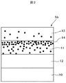
次に、熱交換器5のアルミフィン5bの詳細を図2を参照しながら説明する。図2は本実施例の熱交換器5の表面部分の断面拡大模式図である。
Next, details of the
熱交換器5のアルミフィン5bは、アルミ素材10の表面上に、下地処理層12、親水層11、保護層13の順に形成して構成されている。親水層11及び保護層13の中には脱臭抗菌材14が添加されている。
The aluminum fins 5 b of the
親水層11は、アルミフィン5bの表面を親水性にするためのものであり、下地処理層12を介してアルミ素材10上に形成されている。下地処理層12は親水層11をアルミ素材10上に形成できるように処理するためのものである。保護層13は、熱交換器が完成するまでの保護を目的とするものであり、主にポリエチレングリコールからなり、エアコンを運転したときに熱交換器表面に生成される結露水で洗い流されてしまうものである。従って、エアコンの運転が開始された後は、親水層11が露出されて室内空気と接触することとなる。
The
脱臭抗菌材14は、酸化チタンに亜鉛を担持させたナノ粒子の脱臭抗菌材であり、親水層11の中にアルミ素材側よりも表面側が密に分布されるように添加されている。本実施例では、平均粒径が約10nmであるナノ粒子の脱臭抗菌材14が添加されている。
The deodorizing
上述したように、脱臭抗菌材14が表面側に密に分布されていることにより、僅かな光でも表面に吸着される臭気成分を十分に酸化分解して除去することができ、高い脱臭性能を得ることができる。また、ナノ粒子の脱臭抗菌材14を親水層11に添加したものであるので、従来のように数μmの粒子を添加したものと比較して、親水層11の密着性及び親水性の低下を抑制できると共に、薄い親水層11の表面側に脱臭抗菌材14を密に分布して添加することができる。これによって、熱交換器としての信頼性の向上及び熱交換性能の向上を図ることができる。更には、銅よりイオン化傾向が大きい亜鉛を酸化チタンに担持させているので、結露時に亜鉛と銅パイプとの間で局部電流腐食が発生することを防止できると共に、担持させた亜鉛による脱臭性能の向上を図ることができる。
As described above, since the deodorizing
そして、脱臭抗菌材14は、保護層13の方よりも親水層11の方に多く添加されている。具体的には、親水層11及び保護層13に添加した脱臭抗菌材14の80%以上が親水層11に分布されている。これによって、保護層13を用いた場合に、脱臭抗菌材14の使用量を抑制して安価なものとしつつ、高い脱臭性能を確保することができる。
And the deodorizing
次に、親水層11及び保護層13の成形方法を含む熱交換器5の製造方法について図1及び図2を参照しながら説明する。
Next, a method for manufacturing the
まず、親水層溶液と保護層溶液と脱臭抗菌材14を含む水溶液とを混合し、この混合液をアルミ素材10の表面に焼成して、脱臭抗菌材14がアルミ素材側より表面側に密に分布し且つ保護層13よりも多く含む親水層12と脱臭抗菌材14を少なく含む保護層13とを形成する。脱臭抗菌材14を含む水溶液として、酸化チタンに亜鉛を担持した触媒を使用した。この使用した触媒は、無機コロイド水分散タイプの安定性が高いナノ粒子で構成されており、銅よりイオン化傾向が大きい亜鉛を酸化チタンに担持したものである。
First, a hydrophilic layer solution, a protective layer solution, and an aqueous solution containing the deodorizing
ここで、この触媒作用について簡単に説明する。酸化チタン(Tio2)に熱、光等のエネルギーが加わると、酸化チタンが励起して電子が放出される。すると、この近傍に存在する亜鉛から電子が酸化チタンに移動する。この結果、亜鉛は酸化力の強い亜鉛イオンとなる。ここに臭気成分や菌などの有機物が接触すると、この有機物から電子が取られることで酸化する。分子量の大きい有機物は、最終的に主に水と二酸化炭素になるまで反応が続く。これにより、熱交換器に付着した有機物が分解されるので抗菌・脱臭されることとなる。 Here, this catalytic action will be briefly described. When energy such as heat and light is applied to titanium oxide (Tio2), titanium oxide is excited and electrons are emitted. Then, electrons move from zinc existing in the vicinity to titanium oxide. As a result, zinc becomes a zinc ion having a strong oxidizing power. When organic substances such as odor components and bacteria come into contact therewith, they are oxidized by taking electrons from the organic substances. The organic matter having a large molecular weight continues to react until it finally becomes mainly water and carbon dioxide. Thereby, since the organic substance adhering to the heat exchanger is decomposed, it is antibacterial and deodorized.
この親水層及び保護層の成形に関してさらに具体的に述べる。従来の親水層と保護層は、両者を成形するための混合液を水で薄めてアルミ素材表面に塗布し、焼結の際に保護層の成分を表面に溶出させ、その結果として2層とする作り方をしている。そこで、本実施例では、この水の代わりに、触媒水溶液で親水層及び保護層の混合液を薄めてアルミ素材表面に塗布し、この混合液をアルミ素材10の上に焼成して脱臭抗菌材14を多く含む親水層11と脱臭抗菌材14を少なく含む保護層13とを形成する。このように従来と基本的に同じ工程で親水層11と保護層13とを成形することにより、良好な生産性を維持することができる。そして、触媒水溶液を加えた混合液としてアルミ素材表面に塗布して焼成した結果、図2に示すように親水層に80%以上の脱臭抗菌材14が残存すると共に、表面側に密に分布することを確認した。これは、触媒が保護層13の成分よりも親水層11の成分に分散しやすく、アルミ素材表面に塗布した後に焼成すると、蒸発する水分とともに親水層13の上層に移動するためである。従って、加工工程を増やすことなく効率よく親水層11に脱臭抗菌材14を添加することができる。
This molding of the hydrophilic layer and the protective layer will be described more specifically. The conventional hydrophilic layer and protective layer are prepared by diluting a mixture solution for forming both with water and applying it to the surface of the aluminum material, and eluting the protective layer components on the surface during sintering. How to make Therefore, in this embodiment, instead of this water, the mixed solution of the hydrophilic layer and the protective layer is diluted with an aqueous catalyst solution and applied to the surface of the aluminum material, and this mixed solution is baked on the
図2に示すように触媒の粒子は、親水層11と保護層13の境界近傍に多く分布する。そして、前述したように、熱交換器5を空気調和機に組み込み実際に使用すると、この熱交換器5が蒸発器として作用する時に生成される露によって洗い流される。保護層13が流された後に残った親水層11の表面は、両層の境界であるので、親水層11の表面には、比較的多くの触媒が露出することとなり、結果として触媒が空気と触れる面積が多くなるので、触媒作用を十分に働かせることができる。
As shown in FIG. 2, many catalyst particles are distributed in the vicinity of the boundary between the
アルミ素材10の上に親水層12及び保護層13を形成したアルミフィン5bとした後、そのアルミフィン5bにパイプ貫通孔や段部などをプレス成形する。このアルミフィン5bに銅パイプ5aを貫通させて熱交換器5として組立てる。光触媒を塗布する場合、熱交換器完成品に塗布するよりもフィン素材にあらかじめ塗布しておいたほうが製造しやすい。
After forming the
次に、親水層11の本来の性能である親水性能と脱臭抗菌材14の添加量との関係を図3を参照しながら説明する。図3は本実施例に用いる脱臭抗菌材の添加量と接触角との関係を示す図である。
Next, the relationship between the hydrophilic performance, which is the original performance of the
図3の関係を得るために、本実施例で用いる脱臭抗菌材14の添加量を変えたアルミフィンを試作し、その親水性能を水滴の接触角で評価した。図3において、15(実線)は作製したアルミフィンの初期の親水性能を示し、16(点線)は作製したアルミフィンを24時間流水浸漬する耐久試験後の親水性を示す。その結果、初期の親水性能15は脱臭抗菌材15の添加に影響のないことが確認できた。また、耐久試験後の親水性16では親水性能が向上する傾向があることが判った。従って、本実施例の脱臭抗菌材14は親水性能向上材であるともいえる。これは脱臭抗菌材14が水溶液中でコロイドを形成できることに由来する。すなわち、脱臭抗菌材14がコロイドを形成できるということは、非常に水との相溶性が高いということであり、本実施例の脱臭抗菌材14の表面は親水性なのである。
In order to obtain the relationship shown in FIG. 3, aluminum fins having different amounts of addition of the deodorizing
次に、脱臭性能と脱臭抗菌材14の添加量との関係を図4を参照しながら説明する。図4は本実施例に用いる脱臭抗菌材の添加量とアンモニア脱臭率との関係を示す図である。
Next, the relationship between the deodorizing performance and the addition amount of the deodorizing
図4の関係を得るために、本実施例で用いる脱臭抗菌材14の添加量を変えた10cm角のアルミフィンを試作し、市販の40Lのデシケーター中にこれらのアルミフィンと悪臭の代表であるアンモニア30ppmを入れ、60分経過後の容器内の濃度変化を脱臭率として算出した。図4より、脱臭抗菌材14の添加量が増加するとともに脱臭性能も向上するが、40%以上では脱臭性能は殆ど変わらないことが判った。
In order to obtain the relationship shown in FIG. 4, 10 cm square aluminum fins with different amounts of addition of the deodorizing
次に、金型への影響を確認するために実施したアルミフィン抜き型試験後の金型の磨耗状態の推移を図5に示す。これは、脱臭抗菌材14の添加量を変えたアルミフィンを試作し、銅パイプを通す穴を抜いてみて、このときの金型の磨耗状態を確認したものである。図5において、○は磨耗は見られず、×は金型の磨耗が見られ、金型の寿命が短くなると判断したものである。図5より、脱臭抗菌機能を付加するには、脱臭抗菌材14の添加量を20%以下とすることがアルミフィンを加工後処理する上で好ましいことが判った。
Next, FIG. 5 shows the transition of the wear state of the mold after the aluminum fin punching mold test conducted to confirm the influence on the mold. This is a prototype of an aluminum fin in which the amount of deodorizing
次に、脱臭抗菌材14を10%添加したエアコン用熱交換器を製作し、1m3の密閉容器中でエアコンを運転したときのアンモニアの脱臭性能を確認した結果を図6に示す。18は密閉容器内の自然減衰によるアンモニア残存率特性、19は脱臭抗菌材なしのアンモニア残存率特性、20は脱臭抗菌材14を10%添加した熱交換器を搭載したエアコンによるアンモニア残存率特性を示す。
Next, FIG. 6 shows a result of producing a heat exchanger for an air conditioner to which 10% of the deodorizing
図6から明らかなように、脱臭抗菌材なしの熱交換器を用いたアンモニア残存率特性19が60分で残存率40%になるのに対し、脱臭抗菌材14を10%添加した熱交換器を用いたアンモニア残存率特性20は10分で残存率40%に到達したことが判り、脱臭抗菌材を10%添加することにより、高い脱臭機能をエアコンに付加できることが確認できた。
As can be seen from FIG. 6, the ammonia remaining rate characteristic 19 using the heat exchanger without deodorizing antibacterial material becomes 40% after 60 minutes, whereas the heat exchanger having 10% added deodorizing
本実施例によれば、内部に冷媒を流す銅パイプ5Aと、多数枚並べて銅パイプ5aを貫通させ且つアルミ素材10の上に親水層12を形成したアルミフィン5bとを備えた熱交換器5において、酸化チタンに亜鉛を担持させたナノ粒子の脱臭抗菌材14を親水層12の中にアルミ素材側よりも表面側が密に分布するように添加した構成であるので、安価に、結露による局部電流腐食を防止できると共に親水層12の密着性及び親水性を良好なものとしつつ、僅かな光で十分な脱臭性能を得ることができる。
According to the present embodiment, the
また、本発明によれば、内部に冷媒を流す銅パイプ5aと、多数枚並べて銅パイプ5aを貫通させ且つアルミ素材10の上に親水層12を形成したアルミフィン5bとを備える熱交換器5の製造方法において、酸化チタンに亜鉛を担持させたナノ粒子の脱臭抗菌材14を含む水溶液を親水層溶液に混合し、この混合液をアルミ素材10の表面に焼成して脱臭抗菌材14がアルミ素材側より表面側に密に分布した親水層12を形成するようにしているので、安価に、結露による局部電流腐食を防止できると共に親水層12の密着性及び親水性を良好なものとしつつ、僅かな光で十分な脱臭性能を得ることができる。
In addition, according to the present invention, the
1…筐体、1a…吸込み口、1b…吹出し口、2…化粧枠、3…台枠、4…露受け皿、5…熱交換器、5a…銅パイプ、5b…アルミフィン、6…通風ファン、7…エアフィルター、8…プレフィルター、9…風向羽根、10…アルミ素材、11…親水層、12…下地処理層、13…保護層、14…脱臭抗菌材、15…初期接触角、16…耐久試験終了後の接触角、17…脱臭試験開始60分後のアンモニア脱臭率、18…自然減衰のアンモニア残存率特性、19…脱臭抗菌材なしのアンモニア残存率特性、20…脱臭抗菌加工材ありのアンモニア残存率特性、50…室内ユニット。
DESCRIPTION OF SYMBOLS 1 ... Housing, 1a ... Suction inlet, 1b ... Outlet, 2 ... Cosmetic frame, 3 ... Base frame, 4 ... Dew tray, 5 ... Heat exchanger, 5a ... Copper pipe, 5b ... Aluminum fin, 6 ... Ventilation fan , 7 ... Air filter, 8 ... Pre-filter, 9 ... Wind direction blade, 10 ... Aluminum material, 11 ... Hydrophilic layer, 12 ... Ground treatment layer, 13 ... Protective layer, 14 ... Deodorizing antibacterial material, 15 ... Initial contact angle, 16 ... contact angle after end of durability test, 17 ...
Claims (9)
前記親水層及び前記保護層は酸化チタンに亜鉛を担持させたナノ粒子の脱臭抗菌材を分布して有し、
前記親水層は前記脱臭抗菌材を前記アルミ素材側よりも表面側が密に分布し、
前記脱臭抗菌材は前記保護層の方よりも前記親水層の方に多く分布されたことを特徴とする熱交換器。 Aluminum fins in which a large number of copper pipes flow through the inside, and the copper pipes are arranged side by side and a hydrophilic layer is formed on the aluminum material, and a protective layer is formed on the surface of the hydrophilic layer to be washed away with condensed water. In a heat exchanger with
The hydrophilic layer and the protective layer have a nanoparticle deodorizing antibacterial material in which zinc is supported on titanium oxide ,
The hydrophilic layer surface side densely distributed than the aluminum material side the deodorizing antibacterial material,
The heat exchanger according to claim 1, wherein the deodorizing antibacterial material is distributed more in the hydrophilic layer than in the protective layer .
酸化チタンに亜鉛を担持させたナノ粒子の脱臭抗菌材を含む水溶液と親水層溶液と保護層溶液とを混合した混合液を前記アルミ素材の表面に塗布して焼成することにより、
前記脱臭抗菌材を多く含む前記親水層と前記脱臭抗菌材を少なく含む前記保護層とを形成し、
前記脱臭抗菌材がアルミ素材側より表面側が密に分布した前記親水層を形成することを特徴とする熱交換器の製造方法。 Aluminum fins in which a large number of copper pipes flow through the inside, and the copper pipes are arranged side by side and a hydrophilic layer is formed on the aluminum material, and a protective layer is formed on the surface of the hydrophilic layer to be washed away with condensed water. In a method of manufacturing a heat exchanger comprising:
By applying a mixture of an aqueous solution containing a nanoparticle deodorizing antibacterial material in which zinc is supported on titanium oxide , a hydrophilic layer solution, and a protective layer solution to the surface of the aluminum material and firing ,
Forming the hydrophilic layer containing a lot of the deodorizing antibacterial material and the protective layer containing a small amount of the deodorizing antibacterial material
Method of manufacturing a heat exchanger, characterized in that the deodorizing antibacterial material to form the hydrophilic layer surface side densely distributed than the aluminum material side.
Priority Applications (3)
| Application Number | Priority Date | Filing Date | Title |
|---|---|---|---|
| JP2004329987A JP4464796B2 (en) | 2004-11-15 | 2004-11-15 | Heat exchanger and manufacturing method thereof |
| CNB2005100932505A CN100442003C (en) | 2004-11-15 | 2005-08-19 | Heat-exchanger and making method |
| KR1020050076011A KR100721080B1 (en) | 2004-11-15 | 2005-08-19 | Heat exchanger and method of making the same |
Applications Claiming Priority (1)
| Application Number | Priority Date | Filing Date | Title |
|---|---|---|---|
| JP2004329987A JP4464796B2 (en) | 2004-11-15 | 2004-11-15 | Heat exchanger and manufacturing method thereof |
Publications (3)
| Publication Number | Publication Date |
|---|---|
| JP2006138567A JP2006138567A (en) | 2006-06-01 |
| JP2006138567A5 JP2006138567A5 (en) | 2009-11-05 |
| JP4464796B2 true JP4464796B2 (en) | 2010-05-19 |
Family
ID=36619498
Family Applications (1)
| Application Number | Title | Priority Date | Filing Date |
|---|---|---|---|
| JP2004329987A Expired - Fee Related JP4464796B2 (en) | 2004-11-15 | 2004-11-15 | Heat exchanger and manufacturing method thereof |
Country Status (3)
| Country | Link |
|---|---|
| JP (1) | JP4464796B2 (en) |
| KR (1) | KR100721080B1 (en) |
| CN (1) | CN100442003C (en) |
Families Citing this family (13)
| Publication number | Priority date | Publication date | Assignee | Title |
|---|---|---|---|---|
| JP5010206B2 (en) * | 2006-08-09 | 2012-08-29 | 住友軽金属工業株式会社 | Aluminum fin material for heat exchanger and heat exchanger using the same |
| JP4745193B2 (en) * | 2006-10-19 | 2011-08-10 | 日立アプライアンス株式会社 | Heat exchanger |
| JP5358087B2 (en) * | 2007-12-12 | 2013-12-04 | 住友軽金属工業株式会社 | Aluminum fin material for heat exchanger and heat exchanger using the same |
| JP2010223520A (en) * | 2009-03-24 | 2010-10-07 | Kobe Steel Ltd | Aluminum fin material for heat exchanger |
| US9701177B2 (en) * | 2009-04-02 | 2017-07-11 | Henkel Ag & Co. Kgaa | Ceramic coated automotive heat exchanger components |
| KR20120082278A (en) * | 2011-01-13 | 2012-07-23 | 삼성전자주식회사 | Surface coating layer and heat exchanger including the surface coating layer |
| CN102305573A (en) * | 2011-07-01 | 2012-01-04 | Tcl空调器(中山)有限公司 | Titanium air conditioner and processing method thereof |
| CN102192620B (en) * | 2011-07-01 | 2013-02-13 | Tcl空调器(中山)有限公司 | Titanium heat exchanger for air conditioner and processing method thereof |
| HUE038076T2 (en) * | 2011-07-28 | 2018-09-28 | Nestec Sa | Methods and devices for heating or cooling viscous materials |
| CN103673738A (en) * | 2012-09-17 | 2014-03-26 | 株式会社神户制钢所 | Aluminum radiating sheet for heat exchangers |
| CN103333571B (en) * | 2013-06-24 | 2015-12-02 | 广州慧谷化学有限公司 | For the waterborne antibacterial mildew-proof hydrophilic coating of heat exchanger fin surfaces process |
| WO2019017647A1 (en) * | 2017-07-19 | 2019-01-24 | 엘지전자 주식회사 | Heat exchanger |
| CN111692741B (en) * | 2019-08-01 | 2021-09-28 | 浙江三花智能控制股份有限公司 | Heat exchanger, preparation method thereof and heat exchange system |
Family Cites Families (14)
| Publication number | Priority date | Publication date | Assignee | Title |
|---|---|---|---|---|
| JPS6372592A (en) * | 1986-09-17 | 1988-04-02 | Nitto Electric Ind Co Ltd | Thermal transfer body |
| JPH01240688A (en) * | 1988-03-18 | 1989-09-26 | Kobe Steel Ltd | Aluminum fin material for heat exchanger |
| JP2683812B2 (en) * | 1988-10-05 | 1997-12-03 | 昭和アルミニウム株式会社 | Heat exchanger with aluminum fins |
| JPH02103133A (en) * | 1988-10-13 | 1990-04-16 | Sumitomo Light Metal Ind Ltd | Aluminum fin material for heat exchanger |
| US6300395B1 (en) * | 1994-12-07 | 2001-10-09 | Nikon Parkerizing, Co., Ltd. | Aqueous hydrophilization treatment composition and method for aluminum-containing metal material |
| JPH08261495A (en) * | 1995-03-24 | 1996-10-11 | Mitsui Mining & Smelting Co Ltd | Air cleaning and conditioning apparatus |
| JPH10185357A (en) | 1996-12-20 | 1998-07-14 | Mitsubishi Motors Corp | Heat exchanger |
| JP3689751B2 (en) | 1997-03-12 | 2005-08-31 | シャープ株式会社 | Photocatalyst and air conditioner using the same |
| KR100301262B1 (en) * | 1998-12-04 | 2001-11-22 | 사또미 유따까 | Aluminum alloy fin material with excellent antibacterial and antifungal properties, heat exchanger for air conditioner and fin material for heat exchanger |
| DE19940627A1 (en) * | 1999-08-27 | 2001-03-01 | Abb Patent Gmbh | Heating element for a regenerative heat exchanger and method for producing a heating element |
| CN1133863C (en) * | 2001-04-25 | 2004-01-07 | 北京金基业工贸集团 | Anticorrosion heat sink made of steel |
| KR20030007200A (en) * | 2001-07-16 | 2003-01-23 | 마츠시타 덴끼 산교 가부시키가이샤 | Air conditioner |
| CN1381706A (en) * | 2002-04-26 | 2002-11-27 | 龙口市金穗铜铝材厂 | Nano anticrossion technology for heat radiator by spraying on its inner surface |
| JP2004211936A (en) * | 2002-12-27 | 2004-07-29 | Matsushita Electric Ind Co Ltd | Air conditioner |
-
2004
- 2004-11-15 JP JP2004329987A patent/JP4464796B2/en not_active Expired - Fee Related
-
2005
- 2005-08-19 CN CNB2005100932505A patent/CN100442003C/en not_active Expired - Fee Related
- 2005-08-19 KR KR1020050076011A patent/KR100721080B1/en active IP Right Grant
Also Published As
| Publication number | Publication date |
|---|---|
| CN1776345A (en) | 2006-05-24 |
| KR20060053988A (en) | 2006-05-22 |
| JP2006138567A (en) | 2006-06-01 |
| KR100721080B1 (en) | 2007-05-22 |
| CN100442003C (en) | 2008-12-10 |
Similar Documents
| Publication | Publication Date | Title |
|---|---|---|
| KR100721080B1 (en) | Heat exchanger and method of making the same | |
| US10928083B2 (en) | Air conditioner having air purifying module | |
| US20190030202A1 (en) | Air purifier using ultraviolet rays | |
| JP5948020B2 (en) | HAZARDOUS SUBSTANCE REMOVING DEVICE, AIR PURIFICATION DEVICE USING THE SAME, AND TOXIC SUBSTANCE REMOVING METHOD | |
| DE112015000098T5 (en) | Photocatalyst and vehicle air conditioner having such | |
| JP2001041485A (en) | Air-conditioning device | |
| JP2011056155A (en) | Air cleaner | |
| JP2020506769A (en) | Air filter and air purification module including the same | |
| CN103221117A (en) | A filter and device for treating air | |
| CN100360859C (en) | Embedded into ceiling or suspended on ceiling type air conditioner and air cleaning unit | |
| JP3093953B2 (en) | Heat exchanger with deodorizing function | |
| KR101914451B1 (en) | Air purification module and manufacturing method for the same | |
| JP3280587B2 (en) | Indoor unit of air conditioner | |
| KR101690538B1 (en) | Air Purifier | |
| JP2000317269A (en) | Deodorizing device | |
| KR101877373B1 (en) | Air filter for vehicles | |
| KR200296828Y1 (en) | Air purifying filter device for vehicle air conditioner using photocatalytic filters and adsorbent photocatalytic filters | |
| JP4745193B2 (en) | Heat exchanger | |
| JP4058210B2 (en) | Photocatalyst member | |
| JP2008142427A (en) | Filter, air cleaner using it and air cleaning method | |
| JP5172087B2 (en) | Deodorizing body and deodorizing apparatus using the deodorizing body | |
| US20210221200A1 (en) | Air purification device for vehicle ventilation systems | |
| JP2002071297A (en) | Photocatalytic heat exchanger | |
| JP2001324212A (en) | Air cleaner | |
| JP2005321128A (en) | Cleaning device and air-conditioner |
Legal Events
| Date | Code | Title | Description |
|---|---|---|---|
| A711 | Notification of change in applicant |
Free format text: JAPANESE INTERMEDIATE CODE: A712 Effective date: 20060911 |
|
| A621 | Written request for application examination |
Free format text: JAPANESE INTERMEDIATE CODE: A621 Effective date: 20070202 |
|
| A977 | Report on retrieval |
Free format text: JAPANESE INTERMEDIATE CODE: A971007 Effective date: 20090917 |
|
| A521 | Request for written amendment filed |
Free format text: JAPANESE INTERMEDIATE CODE: A523 Effective date: 20090917 |
|
| A131 | Notification of reasons for refusal |
Free format text: JAPANESE INTERMEDIATE CODE: A131 Effective date: 20091104 |
|
| A521 | Request for written amendment filed |
Free format text: JAPANESE INTERMEDIATE CODE: A523 Effective date: 20100104 |
|
| TRDD | Decision of grant or rejection written | ||
| A01 | Written decision to grant a patent or to grant a registration (utility model) |
Free format text: JAPANESE INTERMEDIATE CODE: A01 Effective date: 20100202 |
|
| A01 | Written decision to grant a patent or to grant a registration (utility model) |
Free format text: JAPANESE INTERMEDIATE CODE: A01 |
|
| A61 | First payment of annual fees (during grant procedure) |
Free format text: JAPANESE INTERMEDIATE CODE: A61 Effective date: 20100219 |
|
| FPAY | Renewal fee payment (event date is renewal date of database) |
Free format text: PAYMENT UNTIL: 20130226 Year of fee payment: 3 |
|
| R150 | Certificate of patent or registration of utility model |
Ref document number: 4464796 Country of ref document: JP Free format text: JAPANESE INTERMEDIATE CODE: R150 Free format text: JAPANESE INTERMEDIATE CODE: R150 |
|
| FPAY | Renewal fee payment (event date is renewal date of database) |
Free format text: PAYMENT UNTIL: 20130226 Year of fee payment: 3 |
|
| FPAY | Renewal fee payment (event date is renewal date of database) |
Free format text: PAYMENT UNTIL: 20140226 Year of fee payment: 4 |
|
| R250 | Receipt of annual fees |
Free format text: JAPANESE INTERMEDIATE CODE: R250 |
|
| S111 | Request for change of ownership or part of ownership |
Free format text: JAPANESE INTERMEDIATE CODE: R313113 |
|
| S531 | Written request for registration of change of domicile |
Free format text: JAPANESE INTERMEDIATE CODE: R313531 |
|
| R350 | Written notification of registration of transfer |
Free format text: JAPANESE INTERMEDIATE CODE: R350 |
|
| R250 | Receipt of annual fees |
Free format text: JAPANESE INTERMEDIATE CODE: R250 |
|
| R250 | Receipt of annual fees |
Free format text: JAPANESE INTERMEDIATE CODE: R250 |
|
| S111 | Request for change of ownership or part of ownership |
Free format text: JAPANESE INTERMEDIATE CODE: R313113 |
|
| R350 | Written notification of registration of transfer |
Free format text: JAPANESE INTERMEDIATE CODE: R350 |
|
| R250 | Receipt of annual fees |
Free format text: JAPANESE INTERMEDIATE CODE: R250 |
|
| R250 | Receipt of annual fees |
Free format text: JAPANESE INTERMEDIATE CODE: R250 |
|
| LAPS | Cancellation because of no payment of annual fees |