JP4459863B2 - Vehicle lighting - Google Patents
Vehicle lighting Download PDFInfo
- Publication number
- JP4459863B2 JP4459863B2 JP2005160984A JP2005160984A JP4459863B2 JP 4459863 B2 JP4459863 B2 JP 4459863B2 JP 2005160984 A JP2005160984 A JP 2005160984A JP 2005160984 A JP2005160984 A JP 2005160984A JP 4459863 B2 JP4459863 B2 JP 4459863B2
- Authority
- JP
- Japan
- Prior art keywords
- optical axis
- fan
- shaped reflection
- light
- light distribution
- Prior art date
- Legal status (The legal status is an assumption and is not a legal conclusion. Google has not performed a legal analysis and makes no representation as to the accuracy of the status listed.)
- Expired - Fee Related
Links
Images


Classifications
-
- F—MECHANICAL ENGINEERING; LIGHTING; HEATING; WEAPONS; BLASTING
- F21—LIGHTING
- F21S—NON-PORTABLE LIGHTING DEVICES; SYSTEMS THEREOF; VEHICLE LIGHTING DEVICES SPECIALLY ADAPTED FOR VEHICLE EXTERIORS
- F21S41/00—Illuminating devices specially adapted for vehicle exteriors, e.g. headlamps
- F21S41/30—Illuminating devices specially adapted for vehicle exteriors, e.g. headlamps characterised by reflectors
- F21S41/32—Optical layout thereof
- F21S41/322—Optical layout thereof the reflector using total internal reflection
Landscapes
- Engineering & Computer Science (AREA)
- General Engineering & Computer Science (AREA)
- Non-Portable Lighting Devices Or Systems Thereof (AREA)
Description
本願発明は、透光部材からなるリフレクタを備えた車両用灯具に関するものである。 The present invention relates to a vehicular lamp provided with a reflector made of a translucent member.
多くの車両用灯具は、灯具前後方向に延びる光軸上に配置された光源からの光をリフレクタにより灯具前方へ向けて反射させるように構成されているが、例えば「特許文献1」に記載されているように、リフレクタが透光部材で構成されたものも知られている。
Many vehicular lamps are configured to reflect light from a light source disposed on an optical axis extending in the front-rear direction of the lamps by a reflector toward the front of the lamps. For example, it is described in “
この「特許文献1」に記載された車両用灯具においては、透光部材からなるリフレクタの外側表面が、複数の全反射プリズムで構成されており、これら各全反射プリズムにおける全反射を利用して光源からの光を灯具前方へ向けて反射させるようになっている。
In the vehicular lamp described in “
また「特許文献2」には、車両用灯具ではないが、透光部材からなるリフレクタの外側表面が、光軸に関して放射状に延びる複数の突条部で構成されるとともに、これら各突条部が、その光軸と直交する平面に沿った断面形状が略V字形状に設定された全反射プリズムで構成されたものが記載されている。 Further, in “Patent Document 2”, although not a vehicle lamp, an outer surface of a reflector made of a translucent member is composed of a plurality of protrusions extending radially with respect to the optical axis, and each of these protrusions is , And a total reflection prism having a substantially V-shaped cross section along a plane perpendicular to the optical axis is described.
上記「特許文献1」および「特許文献2」に記載されているように、リフレクタを透光部材で構成するとともに、その外側表面を複数の全反射プリズムで構成すれば、リフレクタに鏡面処理を施す必要をなくすことができ、灯具製造コスト低減を図ることができる。
As described in the above-mentioned “
その際、車両用灯具として、上記「特許文献2」に記載されているようなリフレクタを備えた構成とすれば、リフレクタの略全領域にわたってその外側表面での全反射を実現することができ、また、この全反射光の向きを内側表面での反射光の向きと略同じ向きに揃えることができるので、光源からの光の多くを灯具前方への照射光として有効に利用することができる。 At that time, as a vehicular lamp, if it is configured to include a reflector as described in the above-mentioned "Patent Document 2", total reflection on the outer surface of the reflector can be realized over substantially the entire region, In addition, since the direction of the totally reflected light can be made to be substantially the same as the direction of the reflected light on the inner surface, much of the light from the light source can be effectively used as irradiation light forward of the lamp.
しかしながら、この「特許文献2」に記載されたリフレクタは、その外側表面が光軸に関して放射状に延びる複数の突条部で構成されているので、このリフレクタからの反射光によって形成される配光パターンは円形の配光パターンとなってしまい、このため車両用灯具として形成すべき配光パターンである横長の配光パターンを形成することができない、という問題がある。 However, since the reflector described in “Patent Document 2” is composed of a plurality of protrusions whose outer surfaces extend radially with respect to the optical axis, a light distribution pattern formed by reflected light from the reflector. Becomes a circular light distribution pattern, and therefore, there is a problem that a horizontally long light distribution pattern that is a light distribution pattern to be formed as a vehicular lamp cannot be formed.
その際、複数の突条部のうちの一部について、その突条部を構成する1対の斜面の傾斜角度を適当に変化させるようにすれば、該突条部からの反射光を、光軸に関して円周接線方向に多少拡散させることが可能となる。その際、各斜面の傾斜角度を大きく変化させると、突条部での全反射を維持できなくなってしまうので、光源光束の有効利用を図るという観点からは、各斜面の傾斜角度の許容変化量は極僅かなものとなってしまう。したがって、このような構成を採用することにより、円形の配光パターンの形状を多少変化させることは可能であるが、横長の配光パターンを形成することはできない、という問題がある。 At that time, if the inclination angle of the pair of slopes constituting the ridge portion is appropriately changed with respect to a part of the plurality of ridge portions, the reflected light from the ridge portion is converted into light. It is possible to diffuse somewhat in the circumferential tangential direction with respect to the axis. At that time, if the inclination angle of each slope is greatly changed, total reflection at the ridges cannot be maintained. From the viewpoint of effective use of the light source luminous flux, the allowable change amount of the inclination angle of each slope. Will be negligible. Therefore, by adopting such a configuration, it is possible to slightly change the shape of the circular light distribution pattern, but there is a problem that a horizontally long light distribution pattern cannot be formed.
本願発明は、このような事情に鑑みてなされたものであって、透光部材からなるリフレクタを備えた車両用灯具において、光源からの光の多くを灯具前方への照射光として有効に利用可能とした上で、横長の配光パターンを形成することができる車両用灯具を提供することを目的とするものである。 The present invention has been made in view of such circumstances, and in a vehicular lamp provided with a reflector made of a translucent member, much of the light from the light source can be effectively used as irradiation light forward of the lamp. Then, it aims at providing the vehicular lamp which can form a horizontally long light distribution pattern.
本願発明は、透光部材からなるリフレクタの外側表面を、光軸に関して放射状に延びる複数の突条部で構成した上で、これを複数の扇形反射領域に区分けするとともに、その構成を扇形反射領域の位置によって異なったものとすることにより、上記目的達成を図るようにしたものである。 In the present invention, the outer surface of the reflector made of a translucent member is configured with a plurality of ridges extending radially with respect to the optical axis, and is divided into a plurality of fan-shaped reflection areas, and the configuration is divided into fan-shaped reflection areas. The above-mentioned purpose is achieved by making it different depending on the position.
すなわち、本願発明に係る車両用灯具は、
灯具前後方向に延びる光軸上に配置された光源と、この光源からの光を灯具前方へ向けて反射させる透光部材からなるリフレクタと、を備えてなる車両用灯具において、
上記リフレクタの外側表面が、上記光軸に関して放射状に延びる複数の突条部で構成されており、
これら各突条部が、上記光軸と直交する平面に沿った断面形状が略V字形状に設定された全反射プリズムで構成されており、
上記リフレクタが、所定本数の上記突条部毎に複数の扇形反射領域に区分けされており、
これら複数の扇形反射領域のうち、上記光軸の左右方向に位置する扇形反射領域が、上記光軸の上下方向に位置する扇形反射領域よりも、上記光源からの光を、上記光軸を含む平面内において該光軸に沿った方向から離れる方向へ反射させるように構成されている、ことを特徴とするものである。
That is, the vehicular lamp according to the present invention is
In a vehicular lamp comprising: a light source disposed on an optical axis extending in the front-rear direction of the lamp; and a reflector made of a translucent member that reflects light from the light source toward the front of the lamp.
The outer surface of the reflector is composed of a plurality of protrusions extending radially with respect to the optical axis,
Each of these protrusions is composed of a total reflection prism whose cross-sectional shape along a plane orthogonal to the optical axis is set to a substantially V-shape,
The reflector is divided into a plurality of fan-shaped reflection areas for each predetermined number of the protrusions,
Of the plurality of fan-shaped reflection areas, the fan-shaped reflection area located in the left-right direction of the optical axis includes light from the light source more than the fan-shaped reflection area located in the vertical direction of the optical axis. In the plane, the light is reflected in a direction away from the direction along the optical axis.
上記「車両用灯具」の種類は特に限定されるものではなく、例えば、ヘッドランプ、フォグランプ、コーナリングランプ、テールランプ、ストップランプ、バックアップランプ、ターンシグナルランプ、デイタイムランニングランプ等が採用可能である。 The type of the “vehicle lamp” is not particularly limited. For example, a head lamp, a fog lamp, a cornering lamp, a tail lamp, a stop lamp, a backup lamp, a turn signal lamp, a daytime running lamp, and the like can be employed.
上記「灯具前後方向」は、車両前後方向と同じ方向であってもよいし、車両前後方向とは異なる方向であってもよい。 The “lamp front-rear direction” may be the same direction as the vehicle front-rear direction, or may be a direction different from the vehicle front-rear direction.
上記「光源」の種類は特に限定されるものではなく、例えば、放電バルブやハロゲンバルブの発光部あるいは発光ダイオード等の発光素子の発光チップ等が採用可能である。 The type of the “light source” is not particularly limited, and for example, a light emitting chip of a light emitting element such as a light emitting portion of a discharge bulb or a halogen bulb or a light emitting diode can be employed.
上記「リフレクタ」は、必ずしも光軸を全周にわたって囲むように形成されていなくてもよい。また、この「リフレクタ」を構成する「透光部材」は、透光性を有する部材であれば、その材質は特に限定されるものではなく、例えば合成樹脂やガラス等が採用可能である。 The “reflector” is not necessarily formed so as to surround the entire optical axis. The “translucent member” constituting the “reflector” is not particularly limited as long as it is a translucent member. For example, synthetic resin or glass can be employed.
上記「突条部」とは、線状に延びる突起部を意味するものである。 The “projection portion” means a projection portion extending linearly.
上記各「扇形反射領域」に含まれる「突条部」の「所定本数」の具体的な値は、特に限定されるものではなく、1本であってもよいし複数本であってもよく、また、各扇形反射領域相互間で同じ本数であってもよいし異なる本数であってもよい。 The specific value of the “predetermined number” of the “projections” included in each of the “fan-shaped reflection areas” is not particularly limited, and may be one or plural. Moreover, the same number may be sufficient between each fan-shaped reflection area | region, and a different number may be sufficient.
上記「複数の扇形反射領域」は、光軸の左右方向に位置する扇形反射領域が、光軸の上下方向に位置する扇形反射領域よりも、光源からの光を、光軸を含む平面内において該光軸に沿った方向から離れる方向へ反射させるように構成されていれば、それ以外の扇形反射領域の具体的な構成は特に限定されるものではない。 The “several fan-shaped reflection areas” are such that the fan-shaped reflection areas located in the left-right direction of the optical axis transmit light from the light source in a plane including the optical axis more than the fan-shaped reflection areas located in the vertical direction of the optical axis. As long as it is configured to reflect in a direction away from the direction along the optical axis, the specific configuration of the other sector-shaped reflection regions is not particularly limited.
上記「光軸を含む平面内において該光軸に沿った方向から離れる方向」は、光軸に対して当該扇形反射領域と同じ側の方向であってもよいし反対側の方向であってもよい。 The “direction away from the direction along the optical axis in the plane including the optical axis” may be the same direction as the fan-shaped reflection region with respect to the optical axis or the opposite direction. Good.
上記「光軸の左右方向に位置する扇形反射領域」が、上記「光軸の上下方向に位置する扇形反射領域」よりも、光源からの光を、光軸を含む平面内において該光軸に沿った方向から離れる方向へ反射させることを実現するための具体的な構成は、特に限定されるものではない。 The above-mentioned “fan-shaped reflection region positioned in the left-right direction of the optical axis” causes light from the light source to be transmitted to the optical axis in a plane including the optical axis, rather than the “fan-shaped reflection region positioned in the vertical direction of the optical axis”. A specific configuration for realizing the reflection in the direction away from the along direction is not particularly limited.
上記光源からの光を「光軸に沿った方向から離れる方向へ反射させる」態様は、光源からの光をすべて光軸に沿った方向から離れる方向へ反射させる態様と、光源からの光の一部を光軸に沿った方向から離れる方向へ反射させる態様とのうちのいずれであってもよい。 In the aspect of “reflecting the light from the light source in the direction away from the direction along the optical axis”, the light from the light source is reflected in the direction of reflecting all the light from the light source in the direction away from the direction along the optical axis. Any of the aspects in which the portion is reflected in a direction away from the direction along the optical axis may be used.
上記「光軸の左右方向に位置する扇形反射領域」とは、光軸を含む水平面近傍に位置する扇形反射領域を意味するものであって、光軸を含む水平面と交差する扇形反射領域が存在する場合には、この扇形反射領域が「光軸の左右方向に位置する扇形反射領域」であり、光軸を含む水平面と交差する扇形反射領域が存在しない場合には、光軸を含む水平断面に最も近接した扇形反射領域が「光軸の左右方向に位置する扇形反射領域」である。 The above "fan-shaped reflection area located in the left-right direction of the optical axis" means a fan-shaped reflection area located near the horizontal plane including the optical axis, and there is a fan-shaped reflection area that intersects the horizontal plane including the optical axis. If the fan-shaped reflection area is a "fan-shaped reflection area located in the left-right direction of the optical axis" and there is no fan-shaped reflection area that intersects the horizontal plane including the optical axis, the horizontal cross section including the optical axis. The fan-shaped reflection area closest to is “fan-shaped reflection area located in the left-right direction of the optical axis”.
上記「光軸の上下方向に位置する扇形反射領域」とは、光軸を含む鉛直面近傍に位置する扇形反射領域を意味するものであって、光軸を含む鉛直面と交差する扇形反射領域が存在する場合には、この扇形反射領域が「光軸の上下方向に位置する扇形反射領域」であり、光軸を含む鉛直面と交差する扇形反射領域が存在しない場合には、光軸を含む鉛直面に最も近接した扇形反射領域が「光軸の上下方向に位置する扇形反射領域」である。 The above-mentioned “fan-shaped reflection area positioned in the vertical direction of the optical axis” means a fan-shaped reflection area located in the vicinity of the vertical plane including the optical axis, and intersects the vertical plane including the optical axis. Is present, the fan-shaped reflection area is a “fan-shaped reflection area positioned in the vertical direction of the optical axis”, and when there is no fan-shaped reflection area intersecting the vertical plane including the optical axis, the optical axis is The fan-shaped reflection area closest to the vertical plane that includes the "fan-shaped reflection area positioned in the vertical direction of the optical axis" is.
上記「光軸の左右方向に位置する扇形反射領域」に該当する扇形反射領域が、光軸の左右両側に1対存在する場合には、その少なくとも一方の扇形反射領域が、光軸の上下方向に位置する扇形反射領域よりも(その際「光軸の上下方向に位置する扇形反射領域」に該当する扇形反射領域が、光軸の上下両側に1対存在する場合には、そのいずれの扇形反射領域よりも)、光源からの光を光軸に沿った方向から離れる方向へ反射させるように構成されていればよい。 When there is a pair of fan-shaped reflective areas corresponding to the above-mentioned "fan-shaped reflective areas located in the left-right direction of the optical axis", at least one of the fan-shaped reflective areas is in the vertical direction of the optical axis. If there is a pair of fan-shaped reflection areas corresponding to “a sector-shaped reflection area positioned in the vertical direction of the optical axis” on both sides of the optical axis, What is necessary is just to be comprised so that the light from a light source may be reflected in the direction away from the direction along an optical axis rather than a reflective area | region.
上記構成に示すように、本願発明に係る車両用灯具は、灯具前後方向に延びる光軸上に配置された光源からの光を、透光部材からなるリフレクタにより灯具前方へ向けて反射させるように構成されているが、そのリフレクタの外側表面は、光軸に関して放射状に延びる複数の突条部で構成されており、これら各突条部は、その光軸と直交する平面に沿った断面形状が略V字形状に設定された全反射プリズムで構成されているので、リフレクタの略全領域にわたってその外側表面での全反射を実現することができ、また、その全反射光の向きを内側表面での反射光の向きと略同じ向きに揃えることができ、これにより光源からの光の多くを灯具前方への照射光として有効に利用することができる。 As shown in the above configuration, the vehicular lamp according to the present invention reflects light from a light source arranged on an optical axis extending in the front-rear direction of the lamp toward the front of the lamp by a reflector made of a translucent member. Although the outer surface of the reflector is composed of a plurality of ridges extending radially with respect to the optical axis, each of the ridges has a cross-sectional shape along a plane perpendicular to the optical axis. Since it is composed of a total reflection prism set in a substantially V shape, it is possible to realize total reflection on the outer surface over substantially the entire area of the reflector, and the direction of the total reflection light on the inner surface. Therefore, most of the light from the light source can be effectively used as irradiation light to the front of the lamp.
その際、上記リフレクタは、所定本数の突条部毎に複数の扇形反射領域に区分けされており、これら複数の扇形反射領域のうち、光軸の左右方向に位置する扇形反射領域が、光軸の上下方向に位置する扇形反射領域よりも、光源からの光を、光軸を含む平面内において該光軸に沿った方向から離れる方向へ反射させるように構成されているので、このリフレクタからの反射光により、横長の配光パターンを形成することができる。 In that case, the reflector is divided into a plurality of fan-shaped reflection areas for each predetermined number of protrusions, and among the plurality of fan-shaped reflection areas, the fan-shaped reflection area located in the left-right direction of the optical axis is the optical axis. The light from the light source is reflected in a direction away from the direction along the optical axis in the plane including the optical axis, rather than the fan-shaped reflection area located in the vertical direction of the reflector. A horizontally long light distribution pattern can be formed by the reflected light.
このように本願発明によれば、透光部材からなるリフレクタを備えた車両用灯具において、光源からの光の多くを灯具前方への照射光として有効に利用可能とした上で、横長の配光パターンを形成することができる。 As described above, according to the present invention, in a vehicular lamp provided with a reflector made of a translucent member, a large amount of light from the light source can be effectively used as irradiation light to the front of the lamp, and a horizontally long light distribution. A pattern can be formed.
上記構成において、光軸の左右方向に位置する扇形反射領域を、光軸の上下方向に位置する扇形反射領域よりも、光源からの光を光軸に沿った方向から離れる方向へ反射させるための具体的な構成が、特に限定されないことは上述したとおりであるが、光軸の上下方向に位置する扇形反射領域の内側表面の、光軸を含む平面に沿った断面形状を、光軸を軸とするとともに光源近傍の点を焦点とする放物線で構成する一方、光軸の左右方向に位置する扇形反射領域の内側表面の、光軸を含む平面に沿った断面形状を、上記放物線を変形させた曲線で構成すれば、次のような作用効果を得ることができる。すなわち、この光軸の左右方向に位置する扇形反射領域からの反射光により形成される配光パターンを、上記断面形状が上記放物線で構成されているとした場合に形成される配光パターンに比して、これを左右方向に引き伸ばしたような横長の配光パターンとすることができる。そしてこれにより、灯具全体からの光照射により形成される配光パターンについても横長の配光パターンとすることができる。その際、上記放物線を変形させた曲線としては、例えば双曲線や楕円等が採用可能である。 In the above configuration, the fan-shaped reflection area positioned in the left-right direction of the optical axis is for reflecting light from the light source in a direction away from the direction along the optical axis than the fan-shaped reflection area positioned in the vertical direction of the optical axis. Although the specific configuration is not particularly limited as described above, the cross-sectional shape along the plane including the optical axis of the inner surface of the fan-shaped reflection region located in the vertical direction of the optical axis is the axis of the optical axis. And a parabola with a cross-sectional shape along the plane including the optical axis of the inner surface of the fan-shaped reflection region located in the left-right direction of the optical axis. The following effects can be obtained by configuring with a curved line. That is, the light distribution pattern formed by the reflected light from the fan-shaped reflection region located in the left-right direction of the optical axis is compared with the light distribution pattern formed when the cross-sectional shape is configured by the parabola. Thus, a horizontally long light distribution pattern that is stretched in the left-right direction can be obtained. And thereby, it can be set as a horizontally long light distribution pattern also about the light distribution pattern formed by the light irradiation from the whole lamp. At that time, as a curve obtained by deforming the parabola, for example, a hyperbola or an ellipse can be adopted.
あるいは、このようにする代わりに、光軸の上下方向に位置する扇形反射領域の内側表面の、光軸を含む平面に沿った断面形状を、光軸を軸とするとともに光源近傍の点を焦点とする放物線で構成する一方、光軸の左右方向に位置する扇形反射領域の内側表面の、光軸を含む平面に沿った断面形状を、上記放物線を該平面内においてその焦点を中心にして傾斜させた曲線で構成すれば、次のような作用効果を得ることができる。すなわち、この光軸の左右方向に位置する扇形反射領域からの反射光により形成される配光パターンを、上記断面形状が上記放物線で構成されているとした場合に形成される配光パターンに比して、これを左右方向に平行移動させた配光パターンとすることができる。そしてこれにより、灯具全体からの光照射により形成される配光パターンを横長の配光パターンとすることができる。 Alternatively, instead of doing this, the cross-sectional shape along the plane including the optical axis of the inner surface of the fan-shaped reflection area positioned in the vertical direction of the optical axis is focused on the point near the light source with the optical axis as the axis. And the cross-sectional shape along the plane including the optical axis of the inner surface of the fan-shaped reflection area located in the left-right direction of the optical axis is inclined with the parabola as the center in the plane. If constituted by the curved lines, the following effects can be obtained. That is, the light distribution pattern formed by the reflected light from the fan-shaped reflection region located in the left-right direction of the optical axis is compared with the light distribution pattern formed when the cross-sectional shape is configured by the parabola. Thus, it is possible to obtain a light distribution pattern that is translated in the left-right direction. And thereby, the light distribution pattern formed by the light irradiation from the whole lamp can be made into a horizontally long light distribution pattern.
また、このようにする代わりに、光軸の上下方向に位置する扇形反射領域の内側表面の、光軸を含む平面に沿った断面形状を、光軸を軸とするとともに光源近傍の点を焦点とする放物線で構成する一方、光軸の左右方向に位置する扇形反射領域の内側表面の、光軸を含む平面に沿った断面形状を、上記放物線を該平面内において平行移動させた曲線で構成すれば、次のような作用効果を得ることができる。すなわち、この光軸の左右方向に位置する扇形反射領域からの反射光により形成される配光パターンを、上記断面形状が上記放物線で構成されているとした場合に形成される配光パターンに比して、これを左右方向に平行移動させた配光パターンとすることができる。そしてこれにより、灯具全体からの光照射により形成される配光パターンを横長の配光パターンとすることができる。その際、光軸を含む平面内において上記放物線を平行移動させる方向は、前後方向であってもよし、左右方向であってもよいし、斜め方向であってもよい。 Instead of doing this, the cross-sectional shape along the plane including the optical axis of the inner surface of the fan-shaped reflection area positioned in the vertical direction of the optical axis is focused on the point near the light source with the optical axis as the axis. On the other hand, the cross-sectional shape along the plane including the optical axis of the inner surface of the fan-shaped reflection region located in the left-right direction of the optical axis is composed of a curve obtained by translating the parabola in the plane. Then, the following effects can be obtained. That is, the light distribution pattern formed by the reflected light from the fan-shaped reflection region located in the left-right direction of the optical axis is compared with the light distribution pattern formed when the cross-sectional shape is configured by the parabola. Thus, it is possible to obtain a light distribution pattern that is translated in the left-right direction. And thereby, the light distribution pattern formed by the light irradiation from the whole lamp can be made into a horizontally long light distribution pattern. At this time, the direction in which the parabola is translated in the plane including the optical axis may be the front-rear direction, the left-right direction, or the oblique direction.
さらに、このようにする代わりに、光軸の上下方向に位置する扇形反射領域の内側表面の、光軸を含む平面に沿った断面形状を、光軸を軸とするとともに光源近傍の点を焦点とする放物線で構成する一方、光軸の左右方向に位置する扇形反射領域の内側表面の、光軸を含む平面に沿った断面形状を、上記放物線を基準線として凹凸状に形成された波形曲線で構成すれば、次のような作用効果を得ることができる。すなわち、この光軸の左右方向に位置する扇形反射領域からの反射光により形成される配光パターンを、上記断面形状が上記放物線で構成されているとした場合に形成される配光パターンに比して、これを左右方向に引き伸ばしたような横長の配光パターンとすることができる。そしてこれにより、灯具全体からの光照射により形成される配光パターンについても横長の配光パターンとすることができる。 In addition, instead of doing this, the cross-sectional shape along the plane including the optical axis of the inner surface of the fan-shaped reflection area positioned in the vertical direction of the optical axis is focused on the point near the light source with the optical axis as the axis. A waveform curve formed in a concavo-convex shape with the parabola as a reference line, the cross-sectional shape along the plane including the optical axis of the inner surface of the fan-shaped reflection region located in the left-right direction of the optical axis The following operational effects can be obtained. That is, the light distribution pattern formed by the reflected light from the fan-shaped reflection region located in the left-right direction of the optical axis is compared with the light distribution pattern formed when the cross-sectional shape is configured by the parabola. Thus, a horizontally long light distribution pattern that is stretched in the left-right direction can be obtained. And thereby, it can be set as a horizontally long light distribution pattern also about the light distribution pattern formed by the light irradiation from the whole lamp.
上記構成において、光軸の左右方向に位置する扇形反射領域を、光軸の上下方向に位置する扇形反射領域よりも、光源からの光を光軸に沿った方向から離れる方向へ反射させるための具体的な構成として、以上の構成例を適宜組み合わせた構成とすることも可能である。 In the above configuration, the fan-shaped reflection area positioned in the left-right direction of the optical axis is for reflecting light from the light source in a direction away from the direction along the optical axis than the fan-shaped reflection area positioned in the vertical direction of the optical axis. As a specific configuration, it is possible to appropriately combine the above configuration examples.
上記構成において、各扇形反射領域の内側表面の光軸と直交する平面に沿った断面形状を、光軸を中心とする円弧形状に設定するとともに、各突条部を構成する1対の斜面の光軸と直交する平面に沿った断面形状を、いずれも凸曲線形状に設定するようにすれば、これらを直線で構成した場合に比して、各扇形反射領域に入射する光源からの光を、灯具正面視において、該扇形反射領域への入射方向と同じ方向へ向けて精度良く反射させることができる。 In the above configuration, the cross-sectional shape along the plane perpendicular to the optical axis of the inner surface of each fan-shaped reflection region is set to an arc shape centered on the optical axis, and a pair of inclined surfaces constituting each protrusion is formed. If the cross-sectional shape along the plane perpendicular to the optical axis is set to a convex curve shape, the light from the light source incident on each fan-shaped reflection area can be compared with the case where these are configured with straight lines. In the front view of the lamp, it can be reflected with high accuracy in the same direction as the incident direction to the fan-shaped reflection region.
以下、図面を用いて、本願発明の実施の形態について説明する。 Hereinafter, embodiments of the present invention will be described with reference to the drawings.
まず、本願発明の第1実施形態について説明する。 First, a first embodiment of the present invention will be described.
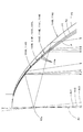
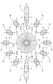
図1は、本実施形態に係る車両用灯具を示す正面図であり、図2は、その側断面図であり、図3は、図2の要部詳細図である。 FIG. 1 is a front view showing a vehicular lamp according to the present embodiment, FIG. 2 is a side sectional view thereof, and FIG. 3 is a detailed view of a main part of FIG.
これらの図に示すように、本実施形態に係る車両用灯具10は、ハイビーム用配光パターンを形成するための光照射を行うヘッドランプユニットとして構成されており、図示しないランプボディ等に組み込まれた状態で用いられるようになっている。
As shown in these drawings, the
この車両用灯具10は、灯具前後方向に延びる光軸Ax上に配置された光源バルブ12と、この光源バルブ12からの光を灯具前方へ向けて反射させるリフレクタ14とを備えてなり、その光軸Axが車両前後方向に延びるように配置された状態で用いられるようになっている。
The
光源バルブ12は、フィラメントを光源12aとするハロゲンバルブであって、その光源12aはバルブ中心軸に沿って延びる線分光源として構成されている。そして、この光源バルブ12は、リフレクタ14の後頂開口部14cに挿着されることにより、その光源12aが光軸Axに沿って配置されるようになっている。
The
リフレクタ14は、透明樹脂製の透光部材で構成されている。この透光部材を構成する透明樹脂としては、例えば無色透明のアクリル樹脂やポリカーボネート樹脂等が採用可能である。
The
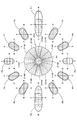
このリフレクタ14は、光軸Axを中心にして、中心角30°毎に12個の扇形反射領域14A、14B、14C、14D、14E、14F、14G、14H、14I、14J、14K、14Lに区分けされている。
The
これら各扇形反射領域14A〜14Lの内側表面14aは、単一曲面で構成されているが、その外側表面14bは、光軸Axに関して放射状に延びる3本の突条部20で構成されている。
The
これら各突条部20は、光軸Axと直交する平面に沿った断面形状(以下、単に「光軸直交断面形状」ともいう)が略V字形状に設定された全反射プリズムで構成されている。その際、各扇形反射領域14A〜14Lにおいて、その外側表面14bを構成する3本の突条部20は、互いに同一形状で構成されている。
Each of the
図4は、図3のIV-IV 線断面詳細図である。また、図5は、光軸Axの真上に位置する扇形反射領域14Aの一部を取り出して、光源12aと共に示す斜視図である。
4 is a detailed sectional view taken along line IV-IV in FIG. FIG. 5 is a perspective view showing a part of the fan-shaped
これらの図にも示すように、扇形反射領域14Aの内側表面14aは、光軸Axを中心とするとともに光源12aの発光中心を焦点とする回転放物面で構成されている。そしてこれにより、光源12aから扇形反射領域14Aに到達した光の一部を、その内側表面14aにおいて光軸Axと平行な方向へ反射させるようになっている。
As shown in these drawings, the
一方、扇形反射領域14Aの外側表面14bを構成する各突条部20は、その1対の斜面がいずれも凸曲面で構成されている。その際、これら各突条部20を構成する1対の斜面の光軸直交断面形状は、略円弧状の凸曲線形状に設定されており、そのプリズム頂角は、内側表面14aに対して面直な断面内において約90°に設定されている。そしてこれにより、光源12aから扇形反射領域14Aの内側表面14aに到達してその内部に進入した光を、各突条部20で全反射させて、これを、灯具正面視において、扇形反射領域14Aへの入射方向と同じ方向へ出射させるようになっている。
On the other hand, as for each
この扇形反射領域14Aの外側表面14bにおける全反射の作用について詳述すると、以下のとおりである。
The action of total reflection on the
すなわち、図4に示すように、扇形反射領域14Aの内側表面14aは、その光軸直交断面形状が光軸Axを中心とする円弧形状になっているので、光源12aからの光は、光軸Axと直交する平面内において、内側表面14aに対して直角に入射し、各突条部20を構成する1対の斜面で2回全反射した後、内側表面14aから出射することとなる。
That is, as shown in FIG. 4, the
その際、同図において2点鎖線で示すように、仮に、各突条部20が直角プリズムで構成されているとした場合には、光源12aから扇形反射領域14Aに入射した光は、各突条部20を構成する1対の斜面で2回全反射した後、反射前と同じ方向へ戻る光となる。この光は、内側表面14aに到達したとき、その到達位置が入射位置から離れているため、内側表面14aに対して直角にはならず、この内側表面14aから出射する際に屈折する。したがって、扇形反射領域14Aからの出射光の方向は、扇形反射領域14Aへの入射方向とは異なる方向になってしまう。
At this time, as shown by a two-dot chain line in the figure, if each
これに対し、本実施形態においては、各突条部20を構成する1対の斜面の光軸直交断面形状が凸曲面形状に設定されているので、光源12aから扇形反射領域14Aに入射した光は、各突条部20を構成する1対の斜面で2回全反射した後、反射前と同じ方向ではなく、やや入射位置寄りの方向へ戻る光となる。この光も、内側表面14aに到達したとき、内側表面14aに対して直角にはならず、この内側表面14aから出射する際に屈折するが、この屈折により、その出射方向が扇形反射領域14Aへの入射方向と同じ方向になるようにすることができる。
On the other hand, in this embodiment, since the optical axis orthogonal cross-sectional shape of the pair of inclined surfaces constituting each
図3および5に示すように、扇形反射領域14Aを構成する各突条部20は、その肉厚が扇形反射領域14Aの内周縁から外周縁へ向けて徐々に増大するとともに、その1対の斜面の曲率が徐々に変化するように形成されている。そしてこれにより、扇形反射領域14Aからの出射光を、その内側表面14aでの反射光と同様、光軸Axと平行な光とするようになっている。
As shown in FIGS. 3 and 5, each
この点について詳述すると、以下のとおりである。 This will be described in detail as follows.
すなわち、扇形反射領域14Aの外側表面14bにおける全反射の作用について説明するため、図4においては、光軸Axと直交する平面内において入射から出射までが行われるものとして説明したが、図3および5に示すように、実際には、光源12aからの光は、扇形反射領域14Aの各位置に対して直角に入射するわけではなく、また、扇形反射領域14Aへの入射位置よりも光軸Axから離れた位置において扇形反射領域14Aから出射する。そこで、各突条部20の肉厚を扇形反射領域14Aの内周縁から外周縁へ向けて徐々に増大させるとともに、その1対の斜面の曲率を徐々に変化させることにより、扇形反射領域14Aからの出射光を光軸Axと平行に出射させるようにしている。
That is, in order to explain the effect of total reflection on the
リフレクタ14を構成する扇形反射領域14A以外の11個の扇形反射領域14B〜14Lのうち、光軸Axの真下に位置する扇形反射領域14Gは、扇形反射領域14Aと全く同様の構成を有している。残り10個の扇形反射領域14B〜14Fおよび14H〜14Lも、扇形反射領域14Aと略同様の構成を有しているが、その内側表面14aの光軸Axを含む平面に沿った断面形状が、扇形反射領域14Aの場合と異なっている。
Of the eleven fan-shaped
図6は、リフレクタ14を構成する各扇形反射領域14A〜14Lの内側表面14aの、光軸Axを含む平面に沿った断面形状を示す図である。
FIG. 6 is a diagram showing a cross-sectional shape along the plane including the optical axis Ax of the
同図において、光軸Axの真上に位置する扇形反射領域14Aの内側表面14aの、光軸Axを含む平面に沿った断面形状(以下、単に「含軸断面形状」ともいう)は、光軸Axを軸とするとともに光源12aの発光中心を焦点とする放物線P(すなわち上記回転放物面におけるその中心軸を含む断面形状)で構成されている。光軸Axの真下に位置する扇形反射領域14Gも同様である。
In the drawing, the cross-sectional shape (hereinafter also simply referred to as “axial cross-sectional shape”) along the plane including the optical axis Ax of the
扇形反射領域14Aの左右両側に隣接する扇形反射領域14B、14Lおよび扇形反射領域14Gの左右両側に隣接する扇形反射領域14F、14Hの内側表面14aの含軸断面形状は、放物線Pを光軸Axから離れる方向へやや拡げた双曲線H1で構成されており、その焦点は光源12aの発光中心に位置設定されている。これにより、これら扇形反射領域14B、14Lおよび14F、14Hは、光源12aからの光を光軸Axから離れる方向へ僅かに拡散反射させるようになっている。
The axial cross-sectional shape of the
扇形反射領域14B、14Lの左右両側に隣接する扇形反射領域14C、14Kおよび扇形反射領域14F、14Hの左右両側に隣接する扇形反射領域14E、14Iの内側表面14aの含軸断面形状は、放物線Pを光軸Axから離れる方向へ双曲線H1よりもやや拡げた双曲線H2で構成されており、その焦点は光源12aの発光中心に位置設定されている。これにより、これら扇形反射領域14C、14Kおよび14E、14Iは、光源12aからの光を光軸Axから離れる方向へ扇形反射領域14B、14Lおよび14F、14Hよりも僅かに大きい角度で拡散反射させるようになっている。
The axial cross-sectional shape of the
光軸Axの真横に位置する左右1対の扇形反射領域14D、14Jの含軸断面形状は、放物線Pを光軸Axから離れる方向へ双曲線H2よりもある程度拡げた双曲線H3で構成されており、その焦点は光源12aの発光中心に位置設定されている。これにより、これら扇形反射領域14D、14Jは、光源12aからの光を光軸Axから離れる方向へ扇形反射領域14C、14Kおよび14E、14Iよりもある程度大きい角度で拡散反射させるようになっている。
The shaft-containing cross-sectional shape of the pair of left and right fan-shaped
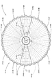
図7は、本実施形態に係る車両用灯具10から前方へ照射される光により灯具前方25mの位置に配置された仮想鉛直スクリーン上に形成されるハイビーム用配光パターンを透視的に示す図である。
FIG. 7 is a perspective view showing a high-beam light distribution pattern formed on a virtual vertical screen arranged at a position 25 m ahead of the lamp by light irradiated forward from the
このハイビーム用配光パターンPH1は、灯具正面方向の消点であるH−Vを中心にして左右方向に拡がる横長の配光パターンとして形成されており、その中心部に高光度領域であるホットゾーンHZを有している。 The high-beam light distribution pattern PH1 is formed as a horizontally long light distribution pattern that extends in the left-right direction around the vanishing point HV in the front direction of the lamp, and a hot zone that is a high-luminance region at the center. Has HZ.
このハイビーム用配光パターンPH1は、リフレクタ14を構成する12個の扇形反射領域14A〜14Lからの反射光によって形成される12個の配光パターンPa〜Plを重畳させた合成配光パターンとして形成されるようになっている。
The high-beam light distribution pattern PH1 is formed as a combined light distribution pattern in which 12 light distribution patterns Pa to Pl formed by reflected light from the 12 fan-shaped
図8は、リフレクタ14を構成する各扇形反射領域14A〜14Lと、ハイビーム用配光パターンPH1を構成する各配光パターンPa〜Plとの対応関係を、リフレクタ14の後方側から見て示す図である。
FIG. 8 is a diagram showing a correspondence relationship between each of the fan-shaped
同図に示すように、これら各配光パターンPa〜Plは、H−Vに対して、各扇形反射領域14A〜14Lの光軸Axに対する角度位置関係と同じ角度位置関係で形成されている。
As shown in the figure, each of the light distribution patterns Pa to Pl is formed with respect to HV in the same angular position relationship as the angular position relationship with respect to the optical axis Ax of each of the fan-shaped
扇形反射領域14A、14Gは、その内側表面14aの含軸断面形状が放物線Pで構成されているので、配光パターンPa、Pgは、H−Vを中心とするスポット状の配光パターンとなっている。その際、これら配光パターンPa、Pgは、光源12aが光軸Axに沿って配置された線分光源として構成されていることから、やや縦長の略長円形に形成されている。
The fan-shaped
扇形反射領域14B、14F、14H、14Lは、その内側表面14aの含軸断面形状が、放物線Pを光軸Axから離れる方向へやや拡げた双曲線H1で構成されているので、配光パターンPb、Pf、Ph、Plは、その内側表面14aの含軸断面形状が放物線Pで構成されているとした場合に形成される2点鎖線で示す配光パターンを、その長手方向に沿ってH−Vから離れる方向へ僅かに拡散させた配光パターンとなっている。
The fan-shaped
扇形反射領域14C、14E、14I、14Kは、その内側表面14aの含軸断面形状が、放物線Pを光軸Axから離れる方向へ双曲線H1よりもやや拡げた双曲線H2で構成されているので、配光パターンPc、Pe、Pi、Pkは、その内側表面14aの含軸断面形状が放物線Pで構成されているとした場合に形成される2点鎖線で示す配光パターンを、その長手方向に沿ってH−Vから離れる方向へ、配光パターンPb、Pf、Ph、Plよりも僅かに大きい角度で拡散させた配光パターンとなっている。
The fan-shaped
扇形反射領域14D、14Jは、その内側表面14aの含軸断面形状が、放物線Pを光軸Axから離れる方向へ双曲線H2よりもある程度拡げた双曲線H3で構成されているので、配光パターンPd、Pjは、その内側表面14aの含軸断面形状が放物線Pで構成されているとした場合に形成される2点鎖線で示す配光パターンを、その長手方向に沿ってH−Vから離れる方向へ、配光パターンPc、Pe、Pi、Pkよりもさらにある程度大きい角度で拡散させた配光パターンとなっている。その際、これら各配光パターンPd、Pjは、H−H線に沿って左右方向に拡がる横長配光パターンとなっている。
Since the fan-shaped
以上詳述したように、本実施形態に係る車両用灯具10は、灯具前後方向に延びる光軸Ax上に配置された光源12aからの光を、透光部材からなるリフレクタ14により灯具前方へ向けて反射させるように構成されているが、そのリフレクタ14の外側表面14bは、光軸Axに関して放射状に延びる複数の突条部20で構成されており、これら各突条部20は、光軸Axと直交する平面に沿った断面形状が略V字形状に設定された全反射プリズムで構成されているので、リフレクタ14の略全領域にわたってその外側表面14bでの全反射を実現することができ、また、その外側表面14bでの全反射光の向きを内側表面14aでの反射光の向きと同じ向きに揃えることも可能となり、これにより光源12aからの光の多くを灯具前方への照射光として有効に利用することができる。
As described in detail above, the
その際、上記リフレクタ14は、3本の突条部20毎に12個の扇形反射領域14A〜14Lに区分けされており、これら12個の扇形反射領域14A〜14Lのうち、光軸Axの左右方向に位置する扇形反射領域14D、14Jが、光軸Axの上下方向に位置する扇形反射領域14A、14Gよりも、光源12aからの光を、光軸Axを含む平面内において光軸Axに沿った方向から離れる方向へ反射させるように構成されているので、このリフレクタ14からの反射光により、ハイビーム用配光パターンPH1を横長の配光パターンとして形成することができる。
At that time, the
具体的には、扇形反射領域14A、14Gの内側表面14aの含軸断面形状が、光軸Axを軸とするとともに光源12aの発光中心を焦点とする放物線Pで構成されており、一方、扇形反射領域14D、14Jの内側表面14aの含軸断面形状が、放物線Pを変形させた曲線である双曲線H3で構成されているので、これら扇形反射領域14D、14Jからの反射光により形成される配光パターンPd、Pjを、含軸断面形状が放物線Pで構成されているとした場合に形成される配光パターンに比して、これを左右方向に引き伸ばしたような横長の配光パターンとすることができる。そしてこれにより、灯具全体からの光照射により形成されるハイビーム用配光パターンPH1についても横長の配光パターンとすることができる。
Specifically, the axial cross-sectional shape of the
このように本実施形態によれば、透光部材からなるリフレクタ14を備えた車両用灯具10において、光源12aからの光の多くを灯具前方への照射光として有効に利用可能とした上で、横長の配光パターンを形成することができる。
As described above, according to the present embodiment, in the
しかも本実施形態においては、扇形反射領域14A、14Gの左右両側に隣接する扇形反射領域14B、14F、14H、14Lからの反射光により形成される2点鎖線で示す配光パターンPb、Pf、Ph、Plが、2点鎖線で示す配光パターンをH−Vから離れる方向へ僅かに拡散させたものとなっており、また、扇形反射領域14C、14E、14I、14Kからの反射光により形成される配光パターンPc、Pe、Pi、Pkが、2点鎖線で示す配光パターンを配光パターンPb、Pf、Ph、Plよりも僅かに大きい角度でH−Vから離れる方向へ拡散させたものとなっているので、ハイビーム用配光パターンPH1を滑らかな光度分布を有するものとすることができる。
Moreover, in the present embodiment, the light distribution patterns Pb, Pf, and Ph indicated by the two-dot chain lines formed by the reflected light from the fan-shaped
また本実施形態においては、各扇形反射領域14A〜14Lの内側表面14aの光軸直交断面形状が、光軸Axを中心とする円弧形状に設定されており、また、各突条部20を構成する1対の斜面の光軸直交断面形状が、いずれも凸曲線形状に設定されているので、これらを直線で構成した場合に比して、各扇形反射領域14A〜14Lに入射する光源12aからの光を、灯具正面視において、該扇形反射領域14A〜14Lへの入射方向と同じ方向へ向けて精度良く反射させることができる。そしてこれにより、各扇形反射領域14A〜14Lからの出射光を、その内側表面14aでの反射光と共に、精度良く制御することができる。
Moreover, in this embodiment, the optical axis orthogonal cross-sectional shape of the
なお、上記第1実施形態においては、そのリフレクタ14が、同一中心角で12個の扇形反射領域14A〜14Lに区分けされているものとして説明したが、これ以外の個数で区分けされた構成あるいは互いに異なる中心角で区分けされた構成とすることも可能である。また、上記第1実施形態においては、各扇形反射領域14A〜14Lの外側表面14bが同一形状の3本の突条部20で構成されているものとして説明したが、これ以外の本数あるいは互いに異なる形状で構成されたものすることも可能である。
In the first embodiment, the
次に、本願発明の第2実施形態について説明する。 Next, a second embodiment of the present invention will be described.
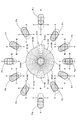
図9、10および11は、本実施形態に係る車両用灯具およびその作用を示す、図6、7および8と同様の図である。 9, 10 and 11 are views similar to FIGS. 6, 7 and 8, showing the vehicular lamp and its operation according to the present embodiment.
これらの図に示すように、本実施形態に係る車両用灯具は、その基本的構成は上記第1実施形態と同様であるが、そのリフレクタ114の反射面形状が、上記第1実施形態のリフレクタ14と一部異なっている。
As shown in these figures, the vehicular lamp according to this embodiment has the same basic configuration as that of the first embodiment, but the shape of the reflecting surface of the
すなわち、本実施形態のリフレクタ114も、上記第1実施形態のリフレクタ14と同様、光軸Axを中心にして、中心角30°毎に12個の扇形反射領域114A、114B、114C、114D、114E、114F、114G、114H、114I、114J、114K、114Lに区分けされているが、これら各扇形反射領域114A〜114Lの内側表面114aの含軸断面形状が上記第1実施形態の場合と異なっている。なお、これら各扇形反射領域114A〜114Lの外側表面の構成については、上記第1実施形態の場合と同様である。
That is, similarly to the
光軸Axの真上に位置する扇形反射領域114Aは、上記第1実施形態の扇形反射領域14Aと全く同様の構成であり、その内側表面114aの含軸断面形状は、光軸Axを軸とするとともに光源12aの発光中心を焦点とする放物線Pで構成されている。光軸Axの真下に位置する扇形反射領域114Gも同様である。
The
扇形反射領域114Aの左右両側に隣接する扇形反射領域114B、114Lおよび扇形反射領域114Gの左右両側に隣接する扇形反射領域114F、114Hの内側表面114aの含軸断面形状は、放物線Pをその焦点を中心にして光軸Axから離れる方向へ僅かに傾斜させた曲線(具体的には光軸Axから僅かに傾斜した軸線を軸Ax1とする放物線P1)で構成されている。これにより、これら扇形反射領域114B、114Lおよび114F、114Hは、光源12aからの光を光軸Axから離れる方向へ僅かに偏向反射させるようになっている。
The axial cross-sectional shape of the
扇形反射領域114B、114Lの左右両側に隣接する扇形反射領域114C、114Kおよび扇形反射領域114F、114Hの左右両側に隣接する扇形反射領域114E、114Iの内側表面114aの含軸断面形状は、放物線Pをその焦点を中心にして光軸Axから離れる方向へ放物線P1よりも僅かに傾斜させた曲線(すなわち軸Ax1よりも僅かに傾斜した軸線を軸Ax2とする放物線P2)で構成されている。これにより、これら扇形反射領域114C、114Kおよび114E、114Iは、光源12aからの光を光軸Axから離れる方向へ扇形反射領域114B、114Lおよび114F、114Hよりも僅かに大きい角度で偏向反射させるようになっている。
The axial cross-sectional shape of the
光軸Axの真横に位置する左右1対の扇形反射領域114D、114Jの含軸断面形状は、放物線Pをその焦点を中心にして光軸Axから離れる方向へ放物線P2よりもある程度傾斜させた曲線(すなわち軸Ax2よりもある程度傾斜した軸線を軸Ax3とする放物線P3)で構成されており、その焦点は光源12aの発光中心に位置設定されている。これにより、これら扇形反射領域114D、114Jは、光源12aからの光を光軸Axから離れる方向へ扇形反射領域114C、114Kおよび114E、114Iよりもある程度大きい角度で偏向反射させるようになっている。
The shaft-containing cross-sectional shape of the pair of left and right fan-shaped
図10に示すように、本実施形態に係る車両用灯具から前方へ照射される光により形成されるハイビーム用配光パターンPH2は、H−Vを中心にして左右方向に拡がる横長の配光パターンとして形成されており、その中心部にホットゾーンHZを有している。 As shown in FIG. 10, the high beam light distribution pattern PH2 formed by the light emitted forward from the vehicular lamp according to the present embodiment is a horizontally long light distribution pattern extending in the left-right direction around HV. And has a hot zone HZ at the center thereof.
このハイビーム用配光パターンPH2は、リフレクタ114を構成する12個の扇形反射領域114A〜114Lからの反射光によって形成される12個の配光パターンPa〜Plを重畳させた合成配光パターンとして形成されるようになっている。
The high-beam light distribution pattern PH2 is formed as a combined light distribution pattern in which 12 light distribution patterns Pa to Pl formed by reflected light from the 12 fan-shaped
図11に示すように、これら各配光パターンPa〜Plは、H−Vに対して、各扇形反射領域114A〜114Lの光軸Axに対する角度位置関係と同じ角度位置関係で形成されている。
As shown in FIG. 11, each of the light distribution patterns Pa to Pl is formed with the same angular position relationship as HV with respect to the optical axis Ax of each of the fan-shaped
扇形反射領域114A、114Gは、その内側表面114aの含軸断面形状が放物線Pで構成されているので、配光パターンPa、PgはH−Vを中心とするスポット状の配光パターンとなっている。
The fan-shaped
扇形反射領域114B、114F、114H、114Lは、その内側表面114aの含軸断面形状が、放物線Pを僅かに傾斜させた放物線P1で構成されているので、配光パターンPb、Pf、Ph、Plは、その内側表面114aの含軸断面形状が放物線Pで構成されているとした場合に形成される2点鎖線で示す配光パターンを、その長手方向に沿ってH−Vから離れる方向へ僅かに移動させたスポット状の配光パターンとなっている。
The fan-shaped
扇形反射領域114C、114E、114I、114Kは、その内側表面114aの含軸断面形状が、放物線P1をさらに僅かに傾斜させた放物線P2で構成されているので、配光パターンPc、Pe、Pi、Pkは、その内側表面114aの含軸断面形状が放物線Pで構成されているとした場合に形成される2点鎖線で示す配光パターンを、その長手方向に沿ってH−Vから離れる方向へ、配光パターンPb、Pf、Ph、Plよりもさらに僅かに移動させたスポット状の配光パターンとなっている。
The fan-shaped
扇形反射領域114D、114Jは、その内側表面114aの含軸断面形状が、放物線P2をさらにある程度傾斜させた放物線P3で構成されているので、配光パターンPd、Pjは、その内側表面114aの含軸断面形状が放物線Pで構成されているとした場合に形成される2点鎖線で示す配光パターンを、その長手方向に沿ってH−Vから離れる方向へ、配光パターンPc、Pe、Pi、Pkよりもさらにある程度移動させたスポット状の配光パターンとなっている。
The fan-shaped
本実施形態においては、各扇形反射領域114A〜114Lからの反射光によって形成される配光パターンPa〜Plは、いずれもスポット状の配光パターンとなっているが、その際、光軸Axの真上および真下に位置する上下1対の扇形反射領域114A、114Gからの反射光により形成される配光パターンPa、PgがH−Vを中心として形成されるのに対して、光軸Axの真横に位置する左右1対の114D、114Jからの反射光により形成される配光パターンPd、PjはH−Vから左右両方向へ移動した位置に形成されるようになっているので、その合成配光パターンとして形成されるハイビーム用配光パターンPH2を横長の配光パターンとすることができる。
In the present embodiment, the light distribution patterns Pa to Pl formed by the reflected light from the respective fan-shaped
したがって、本実施形態の構成を採用した場合においても、上記第1実施形態と同様の作用効果を得ることができる。 Therefore, even when the configuration of the present embodiment is adopted, the same operational effects as those of the first embodiment can be obtained.
しかも本実施形態においては、扇形反射領域114A、114Gの左右両側に隣接する扇形反射領域114B、114F、114H、114Lからの反射光により形成される配光パターンPb、Pf、Ph、Plが、2点鎖線で示す配光パターンをH−Vから離れる方向へ僅かに移動させたものとなっており、また、扇形反射領域114C、114E、114I、114Kからの反射光により形成される配光パターンPc、Pe、Pi、Pkが、2点鎖線で示す配光パターンを配光パターンPb、Pf、Ph、Plよりも僅かに大きい角度でH−Vから離れる方向へ移動させたものとなっているので、ハイビーム用配光パターンPH3を滑らかな光度分布を有するものとすることができる。
In addition, in this embodiment, the light distribution patterns Pb, Pf, Ph, and Pl formed by the reflected light from the fan-shaped
次に、本願発明の第3実施形態について説明する。 Next, a third embodiment of the present invention will be described.
図12、13および14は、本実施形態に係る車両用灯具およびその作用を示す、図6、7および8と同様の図である。 FIGS. 12, 13 and 14 are views similar to FIGS. 6, 7 and 8 showing the vehicular lamp and its operation according to this embodiment.
これらの図に示すように、本実施形態に係る車両用灯具は、その基本的構成は上記第1実施形態と同様であるが、そのリフレクタ214の反射面形状が、上記第1実施形態のリフレクタ14と一部異なっている。
As shown in these figures, the vehicular lamp according to the present embodiment has the same basic configuration as that of the first embodiment, but the shape of the reflecting surface of the
すなわち、本実施形態のリフレクタ214も、上記第1実施形態のリフレクタ14と同様、光軸Axを中心にして、中心角30°毎に12個の扇形反射領域214A、214B、214C、214D、214E、214F、214G、214H、214I、214J、214K、214Lに区分けされているが、これら各扇形反射領域214A〜214Lの内側表面214aの含軸断面形状が上記第1実施形態の場合と異なっている。なお、これら各扇形反射領域214A〜214Lの外側表面の構成については、上記第1実施形態の場合と同様である。
That is, similarly to the
光軸Axの真上に位置する扇形反射領域214Aは、上記第1実施形態の扇形反射領域14Aと全く同様の構成であり、その内側表面214aの含軸断面形状は、光軸Axを軸とするとともに光源12aの発光中心を焦点とする放物線Pで構成されている。光軸Axの真下に位置する扇形反射領域214Gも同様である。
The fan-shaped
扇形反射領域214Aの左右両側に隣接する扇形反射領域214B、214Lおよび扇形反射領域214Gの左右両側に隣接する扇形反射領域214F、214Hの内側表面214aの含軸断面形状は、放物線Pを光軸Axから離れる方向へ僅かに平行移動させた曲線(すなわち光軸Axと平行な軸線を軸Ax4とする放物線P4)で構成されている。これにより、これら扇形反射領域214B、214Lおよび214F、214Hは、光源12aからの光を光軸Axに沿った方向から離れる方向へ僅かに拡散反射させるようになっている。その際、光源12aからの光は、内側表面214aの内周縁寄りの位置では、光軸Axから離れる方向へ反射する一方、内側表面214aの外周縁寄りの位置では、光軸Axに近づく方向へ反射する。これは、放物線P4の焦点が放物線Pの焦点に対して光軸Axから離れる方向へずれた位置にあることによるものである。
The axial cross-sectional shape of the
扇形反射領域214B、214Lの左右両側に隣接する扇形反射領域214C、214Kおよび扇形反射領域214F、214Hの左右両側に隣接する扇形反射領域214E、214Iの内側表面214aの含軸断面形状は、放物線Pを光軸Axから離れる方向へ放物線P4よりも僅かに平行移動させた曲線(すなわち光軸Axと平行な軸線を軸Ax5とする放物線P5)で構成されている。これにより、これら扇形反射領域214C、214Kおよび214E、214Iは、光源12aからの光を光軸Axに沿った方向から離れる方向へ扇形反射領域214B、214Lおよび214F、214Hよりも僅かに大きい角度で拡散反射させるようになっている。
The axial cross-sectional shape of the
光軸Axの真横に位置する左右1対の扇形反射領域214D、214Jの含軸断面形状は、放物線Pを光軸Axから離れる方向へ放物線P5よりもある程度平行移動させた曲線(すなわち光軸Axと平行な軸線を軸Ax6とする放物線P6)で構成されている。これにより、これら扇形反射領域214C、214Kおよび扇形反射領域214F、214Hは、光源12aからの光を光軸Axに沿った方向から離れる方向へ扇形反射領域214B、214Lおよび214F、214Hよりもある程度大きい角度で拡散反射させるようになっている。
The shaft-containing cross-sectional shape of the pair of left and right fan-shaped
図13に示すように、本実施形態に係る車両用灯具から前方へ照射される光により形成されるハイビーム用配光パターンPH3は、H−Vを中心にして左右方向に拡がる横長の配光パターンとして形成されており、その中心部にホットゾーンHZを有している。 As shown in FIG. 13, the high beam light distribution pattern PH3 formed by the light emitted forward from the vehicle lamp according to the present embodiment is a horizontally long light distribution pattern extending in the left-right direction with HV as the center. And has a hot zone HZ at the center thereof.
このハイビーム用配光パターンPH3は、リフレクタ214を構成する12個の扇形反射領域214A〜214Lからの反射光によって形成される12個の配光パターンPa〜Plを重畳させた合成配光パターンとして形成されるようになっている。
The high-beam light distribution pattern PH3 is formed as a combined light distribution pattern in which 12 light distribution patterns Pa to Pl formed by reflected light from the 12 fan-shaped
図14に示すように、これら各配光パターンPa〜Plは、H−Vに対して、各扇形反射領域214A〜214Lの光軸Axに対する角度位置関係と同じ角度位置関係で形成されている。
As shown in FIG. 14, the light distribution patterns Pa to Pl are formed with respect to HV in the same angular position relationship as the angular position relationship with respect to the optical axis Ax of each of the fan-shaped
扇形反射領域214A、214Gは、その内側表面214aの含軸断面形状が放物線Pで構成されているので、配光パターンPa、PgはH−Vを中心とするスポット状の配光パターンとなっている。
The fan-shaped
扇形反射領域214B、214F、214H、214Lは、その内側表面214aの含軸断面形状が、放物線Pを僅かに平行移動させた放物線P4で構成されているので、配光パターンPb、Pf、Ph、Plは、その内側表面214aの含軸断面形状が放物線Pで構成されているとした場合に形成される2点鎖線で示す配光パターンを、その長手方向両側へ僅かに拡散させたスポット状の配光パターンとなっている。
The fan-shaped
扇形反射領域214C、214E、214I、214Kは、その内側表面214aの含軸断面形状が、放物線P4をさらに僅かに平行移動させた放物線P5で構成されているので、配光パターンPc、Pe、Pi、Pkは、その内側表面214aの含軸断面形状が放物線Pで構成されているとした場合に形成される2点鎖線で示す配光パターンを、その長手方向両側へ配光パターンPb、Pf、Ph、Plよりもさらに僅かに拡散させた配光パターンとなっている。
The fan-shaped
扇形反射領域214D、214Jは、その内側表面214aの含軸断面形状が、放物線P5をさらにある程度傾斜させた放物線P6で構成されているので、配光パターンPd、Pjはその内側表面214aの含軸断面形状が放物線Pで構成されているとした場合に形成される2点鎖線で示す配光パターンを、その長手方向両側へ配光パターンPc、Pe、Pi、Pkよりもさらにある程度拡散させた配光パターンとなっている。
The fan-shaped
同図に示すように、配光パターンPb〜PfおよびPh〜Plは、2点鎖線で示す配光パターンを、その長手方向だけでなく、これと直交する方向にも僅かに拡張した形状になっている。これは、放物線P4、P5、P6の焦点が放物線Pの焦点から外れた位置にあることによるものである。 As shown in the figure, the light distribution patterns Pb to Pf and Ph to Pl are formed by slightly extending the light distribution pattern indicated by the two-dot chain line not only in the longitudinal direction but also in the direction orthogonal thereto. ing. This is because the focal points of the parabolas P4, P5, and P6 are out of the focus of the parabola P.
本実施形態においては、各扇形反射領域214A〜214Lからの反射光によって形成される配光パターンPa〜Plのうち、光軸Axの真上および真下に位置する上下1対の扇形反射領域214A、214Gからの反射光により形成される配光パターンPa、PgがH−Vを中心として形成されるのに対して、光軸Axの真横に位置する左右1対の214D、214Jからの反射光により形成される配光パターンPd、PjはH−Vから左右両方向へ拡がる横長の配光パターンとなっているので、灯具全体からの光照射により形成されるハイビーム用配光パターンPH3についても横長の配光パターンとすることができる。
In the present embodiment, among the light distribution patterns Pa to Pl formed by the reflected light from each of the fan-shaped
したがって、本実施形態の構成を採用した場合においても、上記第1実施形態と同様の作用効果を得ることができる。 Therefore, even when the configuration of the present embodiment is adopted, the same operational effects as those of the first embodiment can be obtained.
しかも本実施形態においては、扇形反射領域214A、214Gの左右両側に隣接する扇形反射領域214B、214F、214H、214Lからの反射光により形成される配光パターンPb、Pf、Ph、Plが、2点鎖線で示す配光パターンをその長手方向両側へ僅かに拡散させたものとなっており、また、扇形反射領域214C、214E、214I、214Kからの反射光により形成される配光パターンPc、Pe、Pi、Pkが、2点鎖線で示す配光パターンを配光パターンPb、Pf、Ph、Plよりも僅かに大きい角度でその長手方向両側へ拡散させたものとなっているので、ハイビーム用配光パターンPH3を滑らかな光度分布を有するものとすることができる。
Moreover, in the present embodiment, the light distribution patterns Pb, Pf, Ph, and Pl formed by the reflected light from the fan-shaped
その際、配光パターンPb〜PfおよびPh〜Plは、2点鎖線で示す配光パターンを、その長手方向だけでなく、これと直交する方向にも僅かに拡張した形状になっているので、ハイビーム用配光パターンPH3を一層滑らかな光度分布を有するものとすることができる。 At that time, the light distribution patterns Pb to Pf and Ph to Pl have a shape in which the light distribution pattern indicated by the two-dot chain line is slightly expanded not only in the longitudinal direction but also in the direction orthogonal thereto. The high beam light distribution pattern PH3 can have a smoother light intensity distribution.
次に、本願発明の第4実施形態について説明する。 Next, a fourth embodiment of the present invention will be described.
図15は、本実施形態に係る車両用灯具を示す、図1と同様の図であり、図16は、そのXVI-XVI 線断面詳細図である。また、図17および18は、本実施形態の作用を示す、図7および8と同様の図である。 FIG. 15 is a view similar to FIG. 1 showing the vehicular lamp according to the present embodiment, and FIG. 16 is a detailed sectional view taken along the line XVI-XVI. 17 and 18 are views similar to FIGS. 7 and 8 showing the operation of the present embodiment.
これらの図に示すように、本実施形態に係る車両用灯具310は、その基本的構成は上記第1実施形態と同様であるが、そのリフレクタ314の反射面形状が、上記第1実施形態のリフレクタ14と一部異なっている。
As shown in these drawings, the
すなわち、本実施形態のリフレクタ314も、上記第1実施形態のリフレクタ14と同様、光軸Axを中心にして、中心角30°毎に12個の扇形反射領域314A、314B、314C、314D、314E、314F、314G、314H、314I、314J、314K、314Lに区分けされているが、これら各扇形反射領域314A〜314Lの内側表面314aの含軸断面形状が上記第1実施形態の場合と異なっている。なお、これら各扇形反射領域314A〜314Lの外側表面314bは、上記第1実施形態の場合と同様、光軸Axに関して放射状に延びる3本の突条部20で構成されている。
That is, the
光軸Axの真上に位置する扇形反射領域314Aは、上記第1実施形態の扇形反射領域14Aと全く同様の構成であり、その内側表面314aの含軸断面形状は、光軸Axを軸とするとともに光源12aの発光中心を焦点とする放物線Pで構成されている。この点、残り11個の扇形反射領域314B〜314Lについても、光軸Axの真横に位置する左右1対の扇形反射領域314D、314J以外は同様である。
The
扇形反射領域314D、314Jは、その内側表面314aの含軸断面形状が、放物線Pを基準線として凹凸状に形成された波形曲線で構成されており、光軸Axを中心として同心円状に延びる複数の拡散反射素子314sが滑らかに接続されるようにして形成されている。そして、これら扇形反射領域314D、314Jにおいては、光源12aからの光を光軸Axに関して径方向に拡散反射させるようになっている。
Each of the fan-shaped
なお、図16においては、内側表面314aでの反射光の光路のみを示しているが、外側表面314bの各突条部20で全反射して内側表面314aから出射する光についても、光軸Axに沿った方向から離れる方向へ拡散するものとなる。
In FIG. 16, only the optical path of the reflected light on the
図17に示すように、本実施形態に係る車両用灯具から前方へ照射される光により形成されるハイビーム用配光パターンPH4は、H−Vを中心にして左右方向に拡がる横長の配光パターンとして形成されており、その中心部にホットゾーンHZを有している。 As shown in FIG. 17, the high beam light distribution pattern PH4 formed by the light emitted forward from the vehicular lamp according to the present embodiment is a horizontally long light distribution pattern extending in the left-right direction around HV. And has a hot zone HZ at the center thereof.
このハイビーム用配光パターンPH4は、リフレクタ314を構成する12個の扇形反射領域314A〜314Lからの反射光によって形成される12個の配光パターンPa〜Plを重畳させた合成配光パターンとして形成されるようになっている。
The high-beam light distribution pattern PH4 is formed as a combined light distribution pattern in which 12 light distribution patterns Pa to Pl formed by reflected light from the 12 fan-shaped
図18に示すように、これら各配光パターンPa〜Plは、H−Vに対して、各扇形反射領域314A〜314Lの光軸Axに対する角度位置関係と同じ角度位置関係で形成されている。
As shown in FIG. 18, these light distribution patterns Pa to Pl are formed with respect to HV in the same angular positional relationship as the angular positional relationship with respect to the optical axis Ax of each of the fan-shaped
扇形反射領域314A、314B、314C、314E、314F、314G、314H、314I、314K、314Lは、その内側表面314aの含軸断面形状が放物線Pで構成されているので、配光パターンPa、Pb、Pc、Pe、Pf、Pg、Ph、Pi、Pk、PlはH−Vを中心とするスポット状の配光パターンとなっている。
The fan-shaped
扇形反射領域314D、314Jは、その内側表面314aの含軸断面形状が、放物線Pを基準線として凹凸状に形成された波形曲線で構成されており、その複数の拡散反射素子314sにより光源12aからの光を、光軸Axに関して径方向に拡散反射させるようになっているので、配光パターンPd、Pjは、その内側表面314aの含軸断面形状が放物線Pで構成されているとした場合に形成される2点鎖線で示す配光パターンを、その長手方向両側へ拡散させた配光パターンとなっている。
Each of the fan-shaped
本実施形態においては、各扇形反射領域314A〜314Lからの反射光によって形成される配光パターンPa〜Plのうち、光軸Axの真上および真下に位置する上下1対の扇形反射領域314A、314Gからの反射光により形成される配光パターンPa、PgがH−Vを中心として形成されるのに対して、光軸Axの真横に位置する左右1対の314D、314Jからの反射光により形成される配光パターンPd、PjはH−Vから左右両方向へ拡がる横長の配光パターンとなっているので、灯具全体からの光照射により形成されるハイビーム用配光パターンPH4についても横長の配光パターンとすることができる。
In the present embodiment, among the light distribution patterns Pa to Pl formed by the reflected light from each of the fan-shaped
したがって、本実施形態の構成を採用した場合においても、上記第1実施形態と同様の作用効果を得ることができる。 Therefore, even when the configuration of the present embodiment is adopted, the same operational effects as those of the first embodiment can be obtained.
しかも、本実施形態においては、複数の拡散反射素子314sが、光源12aからの光を左右方向に拡散させるのではなく、光軸Axに関して径方向に拡散させる構成となっているので、配光パターンPd、Pjは、2点鎖線で示す配光パターンを、左右方向に拡張するだけでなく、上下方向にもやや拡張したものとなる。したがって、これら配光パターンPd、Pjを、それ以外の配光パターンPb〜PfおよびPh〜Plと滑らかに接続することができる。
In addition, in the present embodiment, the plurality of diffuse
なお、本実施形態においては、光軸Axの上方に位置する5個の扇形反射領域314A、314B、314C、314K、314Lが、いずれも同様の構成を有しているので、これらをその5個分の中心角を有する1つの扇形反射領域として認識することもでき、また、光軸Axの下方に位置する5個の扇形反射領域314E、314F、314G、314H、314Iについても、これらはいずれも同様の構成を有しているので、これらをその5個分の中心角を有する1つの扇形反射領域として認識することもできる。
In the present embodiment, the five fan-shaped
次に、本願発明の第5実施形態について説明する。 Next, a fifth embodiment of the present invention will be described.
図19、20、21および22は、本実施形態に係る車両用灯具およびその作用を示す、図1、6、7および8と同様の図である。 19, 20, 21 and 22 are views similar to FIGS. 1, 6, 7 and 8 showing the vehicular lamp and its operation according to the present embodiment.
これらの図に示すように、本実施形態に係る車両用灯具410は、その基本的構成は上記第1実施形態と同様であるが、そのリフレクタ414の反射面形状が、上記第1実施形態のリフレクタ14と一部異なっている。
As shown in these drawings, the
すなわち、本実施形態のリフレクタ414も、上記第1実施形態のリフレクタ14と同様、光軸Axを中心にして、中心角30°毎に12個の扇形反射領域414A、414B、414C、414D、414E、414F、414G、414H、414I、414J、414K、414Lに区分けされているが、これら各扇形反射領域414A〜414Lの内側表面414aの含軸断面形状が上記第1実施形態の場合と異なっている。なお、これら各扇形反射領域414A〜414Lの外側表面の構成については、上記第1実施形態の場合と同様である。
That is, the
光軸Axの真上に位置する扇形反射領域414Aは、その内側表面414aが、上記第1実施形態の扇形反射領域14Aの内側表面14aの含軸断面形状を構成する放物線Pを、その焦点を中心にして光軸Axから離れる方向へ僅かに傾斜させた曲線(すなわち光軸Axから僅かに傾斜した軸線を軸Ax7とする放物線P7)で構成されている。これにより、この扇形反射領域414Aは、光源12aからの光を光軸Axから離れる方向へ僅かに偏向反射させるようになっている。扇形反射領域414Aの左右両側に隣接する扇形反射領域414B、414Lおよびその左右両側に隣接する扇形反射領域414C、414Kも同様である。
The fan-shaped
光軸Axの真下に位置する扇形反射領域414Gは、その内側表面414aが、放物線Pをその焦点を中心にして光軸Ax寄りの方向へ僅かに傾斜させた曲線(すなわち光軸Axから軸Ax7とは反対側へ僅かに傾斜した軸線を軸Ax8とする放物線P8)で構成されている。これにより、この扇形反射領域414Gは、光源12aからの光を、光軸Axと一旦交差させるようにした後に光軸Axから離れる方向へ僅かに偏向反射させるようになっている。扇形反射領域414Gの左右両側に隣接する扇形反射領域414F、414Hおよびその左右両側に隣接する扇形反射領域414E、414Iも同様である。
The fan-shaped
光軸Axの真横に位置する左右1対の扇形反射領域414D、414Jの含軸断面形状は、放物線Pをその焦点を中心にして光軸Axから離れる方向へ放物線P7よりもある程度傾斜させた曲線(すなわち軸Ax7よりもある程度傾斜した軸線を軸Ax9とする放物線P9)で構成されており、その焦点は光源12aの発光中心に位置設定されている。これにより、これら扇形反射領域414D、414Jは、光源12aからの光を光軸Axから離れる方向へ扇形反射領域414C、414Kおよび414E、414Iよりもある程度大きい角度で偏向反射させるようになっている。
A pair of left and right fan-shaped
図21に示すように、本実施形態に係る車両用灯具410は、その光照射により付加配光パターンPAを形成するようになっている。この付加配光パターンPAは、図示しない他の車両用灯具からの光照射により形成されるロービーム用配光パターンPLに対して付加的に形成されるものであって、その合成配光パターンとしてハイビーム用配光パターンPH5が形成されるようになっている。
As shown in FIG. 21, the
ロービーム用配光パターンPLは、上端部にカットオフラインCLを有しており、その中心部にカットオフラインCLに沿ったホットゾーンHZLを有している。 The light distribution pattern for low beam PL has a cut-off line CL at the upper end, and has a hot zone HZL along the cut-off line CL at the center.
付加配光パターンPAは、H−Vを中心にして左右方向に拡がる横長の配光パターンとして形成されており、その中心部にホットゾーンHZAを有している。その際、この付加配光パターンPAは、左右方向に拡がるとともに上方へもある程度拡がっているが、下方へはほとんど拡がらない配光パターンとなっている。これは、ハイビーム用配光パターンPH5の一部として形成されるロービーム用配光パターンPLにより、すでにH−Vよりも下方に位置する領域は十分明るく照射された状態にあるので、付加配光パターンPAの重畳により、車両前方路面の近距離から中距離の領域が明るくなり過ぎないようにするための配慮である。 The additional light distribution pattern PA is formed as a horizontally long light distribution pattern extending in the left-right direction around HV, and has a hot zone HZA at the center thereof. At this time, the additional light distribution pattern PA is a light distribution pattern that spreads in the left-right direction and spreads upward to some extent, but hardly spreads downward. This is because the low beam distribution pattern PL formed as a part of the high beam distribution pattern PH5 has already been sufficiently brightly irradiated in the region located below HV. This is a consideration for preventing the area from the short distance to the middle distance on the road surface ahead of the vehicle from becoming too bright due to the superposition of the PA.
そして、このハイビーム用配光パターンPH5においては、ホットゾーンHZLとホットゾーンHZAとが重畳されたものとしてホットゾーンが形成されるようになっている。 In the high beam light distribution pattern PH5, a hot zone is formed as a superposition of the hot zone HZL and the hot zone HZA.
付加配光パターンPAは、リフレクタ414を構成する12個の扇形反射領域414A〜414Lからの反射光によって形成される12個の配光パターンPa〜Plを重畳させた合成配光パターンとして形成されるようになっている。
The additional light distribution pattern PA is formed as a combined light distribution pattern in which twelve light distribution patterns Pa to Pl formed by reflected light from the twelve fan-shaped
図22に示すように、これら各配光パターンPa〜Plは、H−Vに対して、各扇形反射領域414A〜414Lの光軸Axに対する角度位置関係と同じ角度位置関係で形成されている。
As shown in FIG. 22, each of these light distribution patterns Pa to Pl is formed with the same angular position relationship as HV with respect to the optical axis Ax of each of the sector-shaped
光軸Axの上方に位置する扇形反射領域414A、414B、414C、414K、414Lは、その内側表面414aの含軸断面形状が放物線Pを僅かに傾斜させた放物線P7で構成されているので、配光パターンPa、Pb、Pc、Pk、Plは、その内側表面414aの含軸断面形状が放物線Pで構成されているとした場合に形成される2点鎖線で示す配光パターンを、その長手方向に沿って上方側へ多少移動させたスポット状の配光パターンとなっている。
The fan-shaped
光軸Axの下方に位置する扇形反射領域414E、414F、414G、414H、414Iは、その内側表面414aの含軸断面形状が放物線Pを放物線P7とは反対側へ僅かに傾斜させた放物線P8で構成されているので、配光パターンPe、Pf、Pg、Ph、Piは、その内側表面414aの含軸断面形状が放物線Pで構成されているとした場合に形成される2点鎖線で示す配光パターンを、その長手方向に沿って上方側へ多少移動させたスポット状の配光パターンとなっている。
The fan-shaped
扇形反射領域414D、414Jは、その内側表面414aの含軸断面形状が、放物線P7をさらにある程度傾斜させた放物線P9で構成されているので、配光パターンPd、Pjは、その内側表面414aの含軸断面形状が放物線Pで構成されているとした場合に形成される2点鎖線で示す配光パターンを、その長手方向に沿って左方向および右方向へある程度移動させたスポット状の配光パターンとなっている。
The fan-shaped
本実施形態においては、各扇形反射領域414A〜414Lからの反射光によって形成される配光パターンPa〜Plは、いずれもスポット状の配光パターンとなっているが、その形成位置が異なっているので、その合成配光パターンとして形成される付加配光パターンPAを横長でかつ上方へのみ突出する配光パターンとすることができる。
In the present embodiment, the light distribution patterns Pa to Pl formed by the reflected light from the respective fan-shaped
したがって、本実施形態の構成を採用した場合においても、上記第1実施形態と同様の作用効果を得ることができる。 Therefore, even when the configuration of the present embodiment is adopted, the same operational effects as those of the first embodiment can be obtained.
しかも本実施形態においては、光軸Axの上方に位置する扇形反射領域414A、414B、414C、414K、414Lからの反射光によって形成される配光パターンPa、Pb、Pc、Pk、Pl、および光軸Axの下方に位置する扇形反射領域414E、414F、414G、414H、414Iからの反射光によって形成される配光パターンPe、Pf、Pg、Ph、Piのいずれもが、2点鎖線で示す配光パターンを、その長手方向に沿って上方側へ多少移動させたスポット状の配光パターンとなっているので、これらを、扇形反射領域414D、414Jからの反射光によって形成される配光パターンPd、Pjの下方側には拡がらない配光パターンとして形成することができる。そしてこれにより。付加配光パターンPAを、ハイビーム用配光パターンPH5を形成するためにロービーム用配光パターンPLに対して付加的に形成される配光パターンとして適したものとすることができる。
Moreover, in the present embodiment, the light distribution patterns Pa, Pb, Pc, Pk, Pl, and the light formed by the reflected light from the fan-shaped
なお、本実施形態においては、光軸Axの上方に位置する5個の扇形反射領域414A、414B、414C、414K、414Lが、いずれも同様の構成を有しているので、これらをその5個分の中心角を有する1つの扇形反射領域として認識することもでき、また、光軸Axの下方に位置する5個の扇形反射領域414E、414F、414G、414H、414Iについても、これらはいずれも同様の構成を有しているので、これらをその5個分の中心角を有する1つの扇形反射領域として認識することもできる。
In the present embodiment, the five fan-shaped
次に、上記第1実施形態に係る車両用灯具10が、ヘッドランプユニットとしてヘッドランプに組み込まれる場合の具体例について説明する。
Next, a specific example in which the
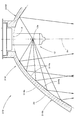
図23は、上記第1実施形態に係る車両用灯具10がヘッドランプユニットとして組み込まれたヘッドランプ50を示す正面図である。
FIG. 23 is a front view showing a
同図に示すように、このヘッドランプ50は、ランプボディ52とその前端開口部に取り付けられた素通し状の透光カバー54とで形成される灯室内に、車両用灯具10が収容された構成となっている。また、上記灯室内には、透光カバー54に沿ってインナパネル56が設けられている。このインナパネル56には、リフレクタ14を囲む楕円形の開口部56aが形成されている。
As shown in the figure, the
このヘッドランプ50においては、車両用灯具10がエイミング機構30を介してランプボディ52に上下方向および左右方向に傾動可能に支持されている。
In the
このエイミング機構30は、L字形に配置された3本のエイミングスクリュウ32を備えてなっている。これら各エイミングスクリュウ32は、その基端部がランプボディ52に回転可能に支持されており、その先端部がエイミングナット34を介して車両用灯具10のリフレクタ14に係合連結されている。このリフレクタ14には、その前端縁の3箇所に、光軸Axに関して放射状に延びるタブ14dが形成されており、これら各タブ14dにエイミングナット34が装着されている。
The aiming
このようにリフレクタ14の前端縁にタブ14dが形成された構成とすることにより、その外側表面14bでの全反射機能を確保した上で、これをヘッドランプ50の一部として構成することができる。
As described above, the
10、310、410 車両用灯具
12 光源バルブ
12a 光源
14、114、214、314、414 リフレクタ
14A、14B、14C、14D、14E、14F、14G、14H、14I、14J、14K、14L、114A、114B、114C、114D、114E、114F、114G、114H、114I、114J、114K、114L、214A、214B、214C、214D、214E、214F、214G、214H、214I、214J、214K、214L、314A、314B、314C、314D、314E、314F、314G、314H、314I、314J、314K、314L、414A、414B、414C、414D、414E、414F、414G、414H、414I、414J、414K、414L 扇形反射領域
14a、114a、214a、314a、414a 内側表面
14b、314b 外側表面
14c 後頂開口部
14d タブ
20 突条部
30 エイミング機構
32 エイミングスクリュウ
34 エイミングナット
50 ヘッドランプ
52 ランプボディ
54 透光カバー
56 インナパネル
56a 開口部
314 拡散反射素子
Ax 光軸
Ax1、Ax2、Ax3、Ax4、Ax5、Ax6、Ax7、Ax8、Ax9 軸
CL カットオフライン
H1、H2、H3 双曲線
HZ、HZA、HZL ホットゾーン
P、P1、P2、P3、P4、P5、P6、P7、P8、P9 放物線
PA 付加配光パターン
PH1、PH2、PH3、PH4、PH5 ハイビーム用配光パターン
PL ロービーム用配光パターン
Pa、Pb、Pc、Pd、Pe、Pf、Pg、Ph、Pi、Pj、Pk、Pl 配光パターン
10, 310, 410 Vehicle lamp 12 Light source bulb 12a Light source 14, 114, 214, 314, 414 Reflector 14A, 14B, 14C, 14D, 14E, 14F, 14G, 14H, 14I, 14J, 14K, 14L, 114A, 114B 114C, 114D, 114E, 114F, 114G, 114H, 114I, 114J, 114K, 114L, 214A, 214B, 214C, 214D, 214E, 214F, 214G, 214H, 214I, 214J, 214K, 214L, 314A, 314B, 314C 314D, 314E, 314F, 314G, 314H, 314I, 314J, 314K, 314L, 414A, 414B, 414C, 414D, 414E, 414F, 414G, 414H, 414I, 414J, 41 K, 414L Fan-shaped reflection area 14a, 114a, 214a, 314a, 414a Inner surface 14b, 314b Outer surface 14c Rear top opening 14d Tab 20 Projection 30 Aiming mechanism 32 Aiming screw 34 Aiming nut 50 Headlamp 52 Lamp body 54 Through Optical cover 56 Inner panel 56a Opening 314 Diffuse reflection element Ax Optical axis Ax1, Ax2, Ax3, Ax4, Ax5, Ax6, Ax7, Ax8, Ax9 axes CL cut-off line H1, H2, H3 Hyperbola HZ, HZA, HZL Hot zone P , P1, P2, P3, P4, P5, P6, P7, P8, P9 Parabolic PA Additional light distribution pattern PH1, PH2, PH3, PH4, PH5 High beam light distribution pattern PL Low beam light distribution pattern Pa, Pb, Pc , Pd, Pe, Pf, Pg, Ph, Pi, Pj, Pk, Pl Light distribution pattern
Claims (6)
上記リフレクタの外側表面が、上記光軸に関して放射状に延びる複数の突条部で構成されており、
これら各突条部が、上記光軸と直交する平面に沿った断面形状が略V字形状に設定された全反射プリズムで構成されており、
上記リフレクタが、所定本数の上記突条部毎に複数の扇形反射領域に区分けされており、
これら複数の扇形反射領域のうち、上記光軸の左右方向に位置する扇形反射領域が、上記光軸の上下方向に位置する扇形反射領域よりも、上記光源からの光を、上記光軸を含む平面内において該光軸に沿った方向から離れる方向へ反射させるように構成されている、ことを特徴とする車両用灯具。 In a vehicular lamp comprising: a light source disposed on an optical axis extending in the front-rear direction of the lamp; and a reflector made of a translucent member that reflects light from the light source toward the front of the lamp.
The outer surface of the reflector is composed of a plurality of protrusions extending radially with respect to the optical axis,
Each of these protrusions is composed of a total reflection prism whose cross-sectional shape along a plane orthogonal to the optical axis is set to a substantially V-shape,
The reflector is divided into a plurality of fan-shaped reflection areas for each predetermined number of the protrusions,
Of the plurality of fan-shaped reflection areas, the fan-shaped reflection area located in the left-right direction of the optical axis includes light from the light source more than the fan-shaped reflection area located in the vertical direction of the optical axis. A vehicular lamp that is configured to reflect in a direction away from a direction along the optical axis in a plane.
上記光軸の左右方向に位置する扇形反射領域の内側表面の、上記光軸を含む平面に沿った断面形状が、上記放物線を変形させた曲線で構成されている、ことを特徴とする請求項1記載の車両用灯具。 The cross-sectional shape along the plane including the optical axis of the inner surface of the fan-shaped reflection region located in the vertical direction of the optical axis is a parabola with the optical axis as the axis and the point near the light source as the focal point. Has been
The cross-sectional shape along the plane including the optical axis of the inner surface of the fan-shaped reflection region located in the left-right direction of the optical axis is configured by a curve obtained by deforming the parabola. The vehicle lamp according to 1.
上記光軸の左右方向に位置する扇形反射領域の内側表面の、上記光軸を含む平面に沿った断面形状が、上記放物線を該平面内において上記焦点を中心にして傾斜させた曲線で構成されている、ことを特徴とする請求項1または2記載の車両用灯具。 The cross-sectional shape along the plane including the optical axis of the inner surface of the fan-shaped reflection region located in the vertical direction of the optical axis is a parabola with the optical axis as the axis and the point near the light source as the focal point. Has been
The cross-sectional shape along the plane including the optical axis of the inner surface of the fan-shaped reflection region located in the left-right direction of the optical axis is composed of a curve in which the parabola is inclined around the focal point in the plane. The vehicular lamp according to claim 1, wherein the vehicular lamp is provided.
上記光軸の左右方向に位置する扇形反射領域の内側表面の、上記光軸を含む平面に沿った断面形状が、上記放物線を該平面内において平行移動させた曲線で構成されている、ことを特徴とする請求項1〜3いずれか記載の車両用灯具。 The cross-sectional shape along the plane including the optical axis of the inner surface of the fan-shaped reflection region located in the vertical direction of the optical axis is a parabola with the optical axis as the axis and the point near the light source as the focal point. Has been
The cross-sectional shape along the plane including the optical axis of the inner surface of the fan-shaped reflection region located in the left-right direction of the optical axis is configured by a curve obtained by translating the parabola in the plane. The vehicular lamp according to any one of claims 1 to 3.
上記光軸の左右方向に位置する扇形反射領域の内側表面の、上記光軸を含む平面に沿った断面形状が、上記放物線を基準線として凹凸状に形成された波形曲線で構成されている、ことを特徴とする請求項1〜4いずれか記載の車両用灯具。 The cross-sectional shape along the plane including the optical axis of the inner surface of the fan-shaped reflection region located in the vertical direction of the optical axis is a parabola with the optical axis as the axis and the point near the light source as the focal point. Has been
The cross-sectional shape along the plane including the optical axis of the inner surface of the fan-shaped reflection region located in the left-right direction of the optical axis is composed of a waveform curve formed in an uneven shape with the parabola as a reference line. The vehicular lamp according to any one of claims 1 to 4, wherein the vehicular lamp is provided.
上記各突条部を構成する1対の斜面の、上記光軸と直交する平面に沿った断面形状が、いずれも凸曲線形状に設定されている、ことを特徴とする請求項1〜5いずれか記載の車両用灯具。 The cross-sectional shape along the plane orthogonal to the optical axis of the inner surface of each fan-shaped reflection region is set to an arc shape centered on the optical axis,
The cross-sectional shape along a plane orthogonal to the optical axis of the pair of slopes constituting each of the protrusions is set to a convex curve shape. A vehicle lamp according to any one of the above.
Priority Applications (2)
| Application Number | Priority Date | Filing Date | Title |
|---|---|---|---|
| JP2005160984A JP4459863B2 (en) | 2005-06-01 | 2005-06-01 | Vehicle lighting |
| US11/444,299 US7223000B2 (en) | 2005-06-01 | 2006-06-01 | Vehicle lighting device |
Applications Claiming Priority (1)
| Application Number | Priority Date | Filing Date | Title |
|---|---|---|---|
| JP2005160984A JP4459863B2 (en) | 2005-06-01 | 2005-06-01 | Vehicle lighting |
Publications (2)
| Publication Number | Publication Date |
|---|---|
| JP2006338985A JP2006338985A (en) | 2006-12-14 |
| JP4459863B2 true JP4459863B2 (en) | 2010-04-28 |
Family
ID=37493918
Family Applications (1)
| Application Number | Title | Priority Date | Filing Date |
|---|---|---|---|
| JP2005160984A Expired - Fee Related JP4459863B2 (en) | 2005-06-01 | 2005-06-01 | Vehicle lighting |
Country Status (2)
| Country | Link |
|---|---|
| US (1) | US7223000B2 (en) |
| JP (1) | JP4459863B2 (en) |
Families Citing this family (20)
| Publication number | Priority date | Publication date | Assignee | Title |
|---|---|---|---|---|
| US10340424B2 (en) | 2002-08-30 | 2019-07-02 | GE Lighting Solutions, LLC | Light emitting diode component |
| DE102007001702B4 (en) * | 2007-01-11 | 2010-04-08 | Airbus Deutschland Gmbh | Lighting device of an aircraft |
| JP4833145B2 (en) * | 2007-04-24 | 2011-12-07 | 株式会社小糸製作所 | Vehicle lighting |
| US7853288B2 (en) * | 2007-08-30 | 2010-12-14 | MacroDisplay, Inc. | Sunlight illuminated and sunlight readable mobile phone |
| JP4356097B1 (en) * | 2008-10-10 | 2009-11-04 | 鈴木 優一 | Lamp having right angle prism in bulb and lighting device using the lamp |
| JP4576490B2 (en) * | 2008-12-09 | 2010-11-10 | フェニックス電機株式会社 | Reflector for light emitting device and light emitting device using the same |
| US8593040B2 (en) | 2009-10-02 | 2013-11-26 | Ge Lighting Solutions Llc | LED lamp with surface area enhancing fins |
| CN104976564B (en) | 2010-04-13 | 2017-11-14 | 株式会社小糸制作所 | Optical unit and vehicle monitor apparatus |
| JP5557665B2 (en) * | 2010-09-17 | 2014-07-23 | 株式会社小糸製作所 | Vehicle lighting |
| US9587820B2 (en) | 2012-05-04 | 2017-03-07 | GE Lighting Solutions, LLC | Active cooling device |
| US9500355B2 (en) | 2012-05-04 | 2016-11-22 | GE Lighting Solutions, LLC | Lamp with light emitting elements surrounding active cooling device |
| US9115865B1 (en) | 2012-06-19 | 2015-08-25 | Forever Gifts, Inc. | Lighting device having light-distributing void |
| JP5762372B2 (en) * | 2012-09-14 | 2015-08-12 | 三菱電機照明株式会社 | Lighting lamp |
| USD692168S1 (en) * | 2013-01-29 | 2013-10-22 | Myotek Pacific Corp. | LED fog lamp |
| DE102013101344A1 (en) * | 2013-02-12 | 2014-08-14 | Hella Kgaa Hueck & Co. | Optical system for a lighting device for vehicles |
| AT518094B1 (en) * | 2015-12-21 | 2018-06-15 | Zkw Group Gmbh | Headlights for vehicles |
| USD796094S1 (en) | 2016-07-19 | 2017-08-29 | Myotek Pacific Corp. | LED fog lamp |
| US10919437B2 (en) | 2017-11-02 | 2021-02-16 | J.W. Speaker Corporation | Headlight matrix systems and methods for a vehicle |
| USD874715S1 (en) | 2018-03-07 | 2020-02-04 | Myotek Holdings, Inc. | LED spot lamp lens |
| JP7455354B2 (en) * | 2019-12-25 | 2024-03-26 | 嶋田プレシジョン株式会社 | Lighting device using reflective material |
Family Cites Families (6)
| Publication number | Priority date | Publication date | Assignee | Title |
|---|---|---|---|---|
| US4839781A (en) | 1988-04-13 | 1989-06-13 | Lexalite International Corporation | Reflector/refractor |
| JPH0424205U (en) * | 1990-06-20 | 1992-02-27 | ||
| JPH05120903A (en) * | 1991-10-25 | 1993-05-18 | Stanley Electric Co Ltd | Reflecting mirror of lighting fixture for vehicle |
| JPH0815002B2 (en) * | 1993-02-26 | 1996-02-14 | スタンレー電気株式会社 | Fog lights |
| DE19624244B4 (en) * | 1996-06-18 | 2010-01-14 | Automotive Lighting Reutlingen Gmbh | Lamp for vehicles |
| EP0854316B1 (en) * | 1997-01-17 | 2005-04-27 | Stanley Electric Co., Ltd. | Projector type lamp |
-
2005
- 2005-06-01 JP JP2005160984A patent/JP4459863B2/en not_active Expired - Fee Related
-
2006
- 2006-06-01 US US11/444,299 patent/US7223000B2/en not_active Expired - Fee Related
Also Published As
| Publication number | Publication date |
|---|---|
| JP2006338985A (en) | 2006-12-14 |
| US20060274546A1 (en) | 2006-12-07 |
| US7223000B2 (en) | 2007-05-29 |
Similar Documents
| Publication | Publication Date | Title |
|---|---|---|
| JP4459863B2 (en) | Vehicle lighting | |
| KR100767253B1 (en) | Vehicular headlamp | |
| JP4068387B2 (en) | Light source unit | |
| JP4393971B2 (en) | Lighting fixtures for vehicles | |
| JP4080780B2 (en) | Light source unit | |
| JP4024628B2 (en) | Vehicle headlamp | |
| JP4002159B2 (en) | Vehicle headlamp | |
| US7275849B2 (en) | LED replacement bulb | |
| JP2006324013A (en) | Vehicular lighting lamp | |
| JP2003059312A (en) | Vehicule lighting device | |
| JP2005251435A (en) | Vehicular headlight | |
| JP5839677B2 (en) | Lighting fixtures for vehicles | |
| JP4574573B2 (en) | Vehicle lamp unit | |
| JP2019003866A (en) | Vehicular lighting fixture | |
| JP5412324B2 (en) | Lighting fixtures for vehicles | |
| EP2360425B1 (en) | Light guiding lens and vehicle light | |
| JP5472594B2 (en) | Vehicle lighting | |
| JP4647650B2 (en) | Light source unit and vehicle lamp | |
| JP2007287449A (en) | Lighting device | |
| JP4865060B2 (en) | Vehicle lighting | |
| JP4697969B2 (en) | Lighting device | |
| JP4865059B2 (en) | Light source unit | |
| JP2023182555A (en) | Beam shaping waveguide for headlight | |
| JP2006172840A (en) | Vehicular headlight | |
| JP2005347148A (en) | Vehicular headlamp |
Legal Events
| Date | Code | Title | Description |
|---|---|---|---|
| A621 | Written request for application examination |
Free format text: JAPANESE INTERMEDIATE CODE: A621 Effective date: 20080324 |
|
| A977 | Report on retrieval |
Free format text: JAPANESE INTERMEDIATE CODE: A971007 Effective date: 20091209 |
|
| TRDD | Decision of grant or rejection written | ||
| A01 | Written decision to grant a patent or to grant a registration (utility model) |
Free format text: JAPANESE INTERMEDIATE CODE: A01 Effective date: 20100209 |
|
| A01 | Written decision to grant a patent or to grant a registration (utility model) |
Free format text: JAPANESE INTERMEDIATE CODE: A01 |
|
| A61 | First payment of annual fees (during grant procedure) |
Free format text: JAPANESE INTERMEDIATE CODE: A61 Effective date: 20100210 |
|
| R150 | Certificate of patent or registration of utility model |
Free format text: JAPANESE INTERMEDIATE CODE: R150 |
|
| FPAY | Renewal fee payment (event date is renewal date of database) |
Free format text: PAYMENT UNTIL: 20130219 Year of fee payment: 3 |
|
| FPAY | Renewal fee payment (event date is renewal date of database) |
Free format text: PAYMENT UNTIL: 20140219 Year of fee payment: 4 |
|
| LAPS | Cancellation because of no payment of annual fees |