JP4448843B2 - Washing machine - Google Patents
Washing machine Download PDFInfo
- Publication number
- JP4448843B2 JP4448843B2 JP2006302252A JP2006302252A JP4448843B2 JP 4448843 B2 JP4448843 B2 JP 4448843B2 JP 2006302252 A JP2006302252 A JP 2006302252A JP 2006302252 A JP2006302252 A JP 2006302252A JP 4448843 B2 JP4448843 B2 JP 4448843B2
- Authority
- JP
- Japan
- Prior art keywords
- water
- detergent
- flow path
- washing
- outer tub
- Prior art date
- Legal status (The legal status is an assumption and is not a legal conclusion. Google has not performed a legal analysis and makes no representation as to the accuracy of the status listed.)
- Active
Links
- 238000005406 washing Methods 0.000 title claims description 192
- XLYOFNOQVPJJNP-UHFFFAOYSA-N water Substances O XLYOFNOQVPJJNP-UHFFFAOYSA-N 0.000 claims description 277
- 239000003599 detergent Substances 0.000 claims description 214
- 230000007246 mechanism Effects 0.000 claims description 44
- 238000000034 method Methods 0.000 claims description 26
- 238000005192 partition Methods 0.000 claims description 24
- 230000002093 peripheral effect Effects 0.000 claims description 19
- 239000007788 liquid Substances 0.000 claims description 16
- 238000001514 detection method Methods 0.000 claims description 15
- 239000004744 fabric Substances 0.000 claims description 14
- 230000008569 process Effects 0.000 claims description 14
- 238000004090 dissolution Methods 0.000 claims description 12
- 238000001035 drying Methods 0.000 description 24
- 238000003756 stirring Methods 0.000 description 14
- 239000000843 powder Substances 0.000 description 10
- 230000018044 dehydration Effects 0.000 description 9
- 238000006297 dehydration reaction Methods 0.000 description 9
- 230000003014 reinforcing effect Effects 0.000 description 9
- 239000002585 base Substances 0.000 description 6
- 239000000693 micelle Substances 0.000 description 6
- 230000009471 action Effects 0.000 description 5
- 239000003795 chemical substances by application Substances 0.000 description 5
- 239000000498 cooling water Substances 0.000 description 4
- 230000001965 increasing effect Effects 0.000 description 4
- 239000004094 surface-active agent Substances 0.000 description 4
- 239000010409 thin film Substances 0.000 description 4
- 238000001816 cooling Methods 0.000 description 3
- 230000000694 effects Effects 0.000 description 3
- 238000002844 melting Methods 0.000 description 3
- 230000008018 melting Effects 0.000 description 3
- 238000005507 spraying Methods 0.000 description 3
- 239000008400 supply water Substances 0.000 description 3
- 239000002699 waste material Substances 0.000 description 3
- 230000008859 change Effects 0.000 description 2
- 230000001276 controlling effect Effects 0.000 description 2
- 230000007423 decrease Effects 0.000 description 2
- 238000010586 diagram Methods 0.000 description 2
- 125000001165 hydrophobic group Chemical group 0.000 description 2
- 238000012544 monitoring process Methods 0.000 description 2
- 230000035515 penetration Effects 0.000 description 2
- 239000000126 substance Substances 0.000 description 2
- 239000000271 synthetic detergent Substances 0.000 description 2
- CNGYZEMWVAWWOB-VAWYXSNFSA-N 5-[[4-anilino-6-[bis(2-hydroxyethyl)amino]-1,3,5-triazin-2-yl]amino]-2-[(e)-2-[4-[[4-anilino-6-[bis(2-hydroxyethyl)amino]-1,3,5-triazin-2-yl]amino]-2-sulfophenyl]ethenyl]benzenesulfonic acid Chemical compound N=1C(NC=2C=C(C(\C=C\C=3C(=CC(NC=4N=C(N=C(NC=5C=CC=CC=5)N=4)N(CCO)CCO)=CC=3)S(O)(=O)=O)=CC=2)S(O)(=O)=O)=NC(N(CCO)CCO)=NC=1NC1=CC=CC=C1 CNGYZEMWVAWWOB-VAWYXSNFSA-N 0.000 description 1
- 102000004190 Enzymes Human genes 0.000 description 1
- 108090000790 Enzymes Proteins 0.000 description 1
- 238000010521 absorption reaction Methods 0.000 description 1
- 238000009825 accumulation Methods 0.000 description 1
- 239000003513 alkali Substances 0.000 description 1
- 239000012752 auxiliary agent Substances 0.000 description 1
- 230000004323 axial length Effects 0.000 description 1
- 230000008901 benefit Effects 0.000 description 1
- 230000000903 blocking effect Effects 0.000 description 1
- 210000004556 brain Anatomy 0.000 description 1
- 238000004140 cleaning Methods 0.000 description 1
- 238000009833 condensation Methods 0.000 description 1
- 230000005494 condensation Effects 0.000 description 1
- 238000005520 cutting process Methods 0.000 description 1
- 230000003247 decreasing effect Effects 0.000 description 1
- 238000007865 diluting Methods 0.000 description 1
- 238000002845 discoloration Methods 0.000 description 1
- 238000010981 drying operation Methods 0.000 description 1
- 230000002708 enhancing effect Effects 0.000 description 1
- 238000001704 evaporation Methods 0.000 description 1
- 239000012530 fluid Substances 0.000 description 1
- 238000011086 high cleaning Methods 0.000 description 1
- 238000007373 indentation Methods 0.000 description 1
- 238000009434 installation Methods 0.000 description 1
- 150000002632 lipids Chemical class 0.000 description 1
- 239000004570 mortar (masonry) Substances 0.000 description 1
- 239000012466 permeate Substances 0.000 description 1
- 238000003825 pressing Methods 0.000 description 1
- 238000005086 pumping Methods 0.000 description 1
- 230000009467 reduction Effects 0.000 description 1
- 230000001105 regulatory effect Effects 0.000 description 1
- 239000008237 rinsing water Substances 0.000 description 1
- 238000005063 solubilization Methods 0.000 description 1
- 230000007928 solubilization Effects 0.000 description 1
- 230000003381 solubilizing effect Effects 0.000 description 1
- 239000007921 spray Substances 0.000 description 1
- 230000007480 spreading Effects 0.000 description 1
- 238000003892 spreading Methods 0.000 description 1
- 229920003002 synthetic resin Polymers 0.000 description 1
- 239000000057 synthetic resin Substances 0.000 description 1
- 239000008399 tap water Substances 0.000 description 1
- 235000020679 tap water Nutrition 0.000 description 1
- 238000011144 upstream manufacturing Methods 0.000 description 1
- 238000009423 ventilation Methods 0.000 description 1
- 238000010792 warming Methods 0.000 description 1
Images


Landscapes
- Detail Structures Of Washing Machines And Dryers (AREA)
Description
本発明は、粉末洗剤の溶解手段と洗濯水の循環手段を備えた洗濯機に関する。 The present invention relates to a washing machine including a powder detergent dissolving means and a washing water circulation means.
粉末洗剤を溶解した後に洗いに供することは、洗い初期から所望の洗剤濃度で洗えることから洗浄力を高めるのに効果がある。また、水温が低く洗剤が溶けにくくなる冬場においても洗剤の溶け残りを防止できる効果がある。さらに、洗剤を少量の水で溶かし高濃度洗剤液を生成し(洗剤濃度は10〜15倍が好適)、これを洗濯物に振り掛けた後で、規定水位まで給水して洗うことで、高濃度洗剤液に触れた汚れが取れやすい状態になるため、洗浄力を大幅に向上できる。 When the powder detergent is dissolved and then subjected to washing, it can be washed at a desired detergent concentration from the beginning of washing, so that it is effective for enhancing the washing power. In addition, there is an effect of preventing the detergent from remaining undissolved even in winter when the water temperature is low and the detergent is difficult to dissolve. Furthermore, the detergent is dissolved in a small amount of water to produce a high-concentration detergent solution (detergent concentration is preferably 10 to 15 times). Since it becomes easy to remove dirt touching the detergent solution, the cleaning power can be greatly improved.
粉末洗剤溶解手段としては、専用の洗剤溶かし装置による方法、洗濯槽の回転で洗剤を溶かす方法、洗濯槽底部に設けた攪拌翼で洗剤を溶かす方法などが用いられている。 As the powder detergent dissolving means, a method using a dedicated detergent melting device, a method of dissolving the detergent by rotating the washing tub, a method of dissolving the detergent with a stirring blade provided at the bottom of the washing tub, and the like are used.
専用の洗剤溶かし装置による方法としては、底部に攪拌翼を有する箱状の洗剤溶解容器に洗剤と水を入れ、攪拌翼を回転することで洗剤を溶解し高濃度の洗剤液を生成し、この洗剤液を水で希釈しながら洗濯槽へ供給する方法がある。 As a method using a dedicated detergent dissolver, detergent and water are put in a box-shaped detergent dissolution container having a stirring blade at the bottom, and the detergent is dissolved by rotating the stirring blade to produce a high-concentration detergent solution. There is a method of supplying a detergent solution to a washing tub while diluting with water.
外槽を回転して洗剤を溶かす方法としては、外槽の底に洗剤を投入し、洗濯槽の底面が水に触れる程度まで外槽に給水し、洗濯槽を回転して水と洗剤を攪拌することで洗剤を溶かす方法がある。 The method of dissolving the detergent by rotating the outer tub is to put the detergent into the bottom of the outer tub, supply water to the outer tub until the bottom of the washing tub touches the water, and rotate the washing tub to stir the water and detergent. There is a way to dissolve the detergent.
攪拌翼で洗剤を溶かす方法としては、洗濯槽底面と攪拌翼裏面との間に洗剤を入れ、攪拌翼の裏面が水に浸かる程度まで給水を行い、攪拌翼を正逆転し水と洗剤を攪拌し洗剤を溶かす方法がある。 As a method of dissolving detergent with a stirring blade, put the detergent between the bottom of the washing tub and the back of the stirring blade, supply water until the back of the stirring blade is immersed in water, and reverse the stirring blade to reverse the water and detergent. There is a method to dissolve detergent.
また、循環ポンプを有し、外槽内に溜めた少量の洗濯水をくみ上げ洗濯槽内の洗濯物に散布し、洗濯液をむらなく洗濯物に染み込ませることで節水を可能とした洗濯機がある。 There is also a washing machine that has a circulation pump, draws up a small amount of washing water stored in the outer tub, spreads it on the laundry in the washing tub, and evenly soaks the washing liquid into the laundry to save water. is there.
専用の洗剤溶かし装置による方法は、確実に洗剤を溶かすことが出来、かつ溶解した高濃度洗剤液を水で希釈し供給するので、洗剤濃度の制御が容易である利点がある。しかし、洗剤溶かし装置のためにコストが高くなること、かつ洗剤溶解容器(容積500mL程度に攪拌装置が付く)の設置スペースが必要である。 The method using the dedicated detergent dissolving apparatus has the advantage that the detergent concentration can be easily controlled because the detergent can be surely dissolved and the dissolved high-concentration detergent solution is diluted with water and supplied. However, the cost is increased due to the detergent melting apparatus, and the installation space for the detergent dissolving container (with a stirring device of about 500 mL in volume) is required.
洗濯槽の回転による方法や攪拌翼の正逆転による方法は、洗濯槽の底部あるいは攪拌翼の裏面まで水を入れる必要があるため、洗剤溶かし時の水量は一定になる。このため、洗濯物の量が多い(洗剤量が多い)場合は濃い洗剤液ができ、洗濯物の量が少ない場合(洗剤量が少ない)場合は洗剤濃度が薄くなり、溶かし時の洗剤濃度を一定にすることはできない。 In the method using the rotation of the washing tub and the method using the forward and reverse rotation of the stirring blade, it is necessary to put water up to the bottom of the washing tub or the back surface of the stirring blade. For this reason, when the amount of laundry is large (the amount of detergent is large), a thick detergent solution is formed. When the amount of laundry is small (the amount of detergent is small), the detergent concentration is reduced, and the detergent concentration at the time of melting is reduced. It cannot be made constant.
また、洗濯槽の回転軸が水平あるいはやや斜めになっているドラム式洗濯機では、円筒の内周部に水が溜まり、洗濯槽に水が触れる程度の給水量では洗剤を溶かすのには少量すぎ、洗濯槽の回転では十分に溶解できない。さらに、洗濯槽を回転すると洗濯槽の脱水孔から、未溶解の洗剤や水が入り洗濯物に付着吸水され、水量がますます少なくなってしまう。さらに、攪拌翼を有していないため、攪拌翼による方法は不可能である。 In addition, in a drum-type washing machine where the rotation axis of the washing tub is horizontal or slightly inclined, water is collected on the inner periphery of the cylinder, and a small amount of water is needed to dissolve the detergent when the amount of water supply is sufficient to touch the washing tub. It is not possible to dissolve sufficiently by rotating the washing tub. Further, when the washing tub is rotated, undissolved detergent or water enters from the dewatering hole of the washing tub and adheres to the laundry and absorbs water, so that the amount of water becomes smaller. Furthermore, since it does not have a stirring blade, a method using a stirring blade is impossible.
本発明の目的は、簡単な構成で洗剤の溶解と洗剤液の循環を実現でき、さらに溶解時の洗剤濃度の制御が可能な洗濯機を提供することにある。 An object of the present invention is to provide a washing machine that can realize the dissolution of detergent and the circulation of detergent liquid with a simple configuration, and can control the concentration of the detergent during dissolution.
上記目的を達成するために本発明における洗濯機の特徴とするところは、洗濯水を溜める外槽内に回転可能に設けた洗濯兼脱水槽である内槽と、該内槽を回転駆動する駆動装置と、該外槽に洗濯水を給水する給水機構と、前記外槽底部に溜めた洗濯水を循環する洗濯水循環機構と、前記外槽内の水を排水する排水機構と、前記外槽内の水位を検出する水位検出手段と、前記内槽に投入された洗濯物の量を検出する布量検出手段と、前記駆動機構と給水機構と排水機構と洗濯水循環機構を制御する制御装置を備えた洗濯機において、前記洗濯水循環機構は、循環ポンプと該循環ポンプと前記外槽底部とを接続する流路とで構成され、該流路は前記外槽底部から前記循環ポンプへ至る第1の流路と、前記循環ポンプから前記外槽底部へ至る第2の流路と、前記循環ポンプから前記外槽上部へ至る第3の流路とで構成され、前記制御手段は前記循環ポンプの回転方向を変えることで前記第2の流路と前記第3の流路とを切り替えるように構成する。 In order to achieve the above object, the washing machine according to the present invention is characterized by an inner tub which is a washing and dewatering tub provided rotatably in an outer tub for storing washing water, and a drive for rotating the inner tub. An apparatus, a water supply mechanism for supplying wash water to the outer tub, a wash water circulation mechanism for circulating wash water stored in the bottom of the outer tub, a drainage mechanism for draining water in the outer tub, and the inner tub A water level detecting means for detecting the water level of the water, a cloth amount detecting means for detecting the amount of laundry put in the inner tub, a control device for controlling the drive mechanism, the water supply mechanism, the drainage mechanism, and the washing water circulation mechanism. In the washing machine, the washing water circulation mechanism includes a circulation pump and a flow path connecting the circulation pump and the bottom of the outer tub, and the flow path is a first that extends from the bottom of the outer tub to the circulation pump. And a second channel extending from the circulation pump to the bottom of the outer tank And a third flow path from the circulation pump to the upper part of the outer tub, and the control means changes the rotation direction of the circulation pump to change the second flow path and the third flow path. And to switch between.
また、前記循環ポンプはモータとモータ軸に締結したランナーと該ランナーを覆う円筒状のケーシングとで構成され、該ケーシングはモータの反対側端面中央に吸い込み口を備え、内周面の内側に突出した隔壁を有し、該隔壁を挟んで第1の吐出口と第2の吐出口とを備え、該第1の吐出口を前記第2の流路に接続し、該第2の吐出口を前記第3の流路に接続するように構成する。 The circulation pump includes a motor, a runner fastened to the motor shaft, and a cylindrical casing that covers the runner. The casing has a suction port at the center of the opposite end surface of the motor and protrudes to the inside of the inner peripheral surface. A first discharge port and a second discharge port sandwiching the partition wall, the first discharge port being connected to the second flow path, and the second discharge port being The third channel is configured to be connected.
さらに、前記外槽は底部に凹状の水受け部を備え、該水受け部に前記第1の流路入口と前記第2の流路出口を接続するように構成する。 Further, the outer tub is provided with a concave water receiving portion at the bottom, and is configured to connect the first channel inlet and the second channel outlet to the water receiving portion.
また、前記水受け部は上面を略半分覆う隔壁を有し、前記第2の流路の出口を前記隔壁の下部に設けるように構成する。 Further, the water receiving portion has a partition that covers approximately half of the upper surface, and the outlet of the second flow path is provided at the lower portion of the partition.
さらに、前記第2の流路の出口に該出口から吐出される水を前記第1の流路入口に向かわせる整流部材を設けるように構成する。 Further, a rectifying member is provided at the outlet of the second channel to direct water discharged from the outlet to the inlet of the first channel.
さらに、前記水受け部底面は、前記第2の流路出口部が高く前記第1の流路入口部が低い傾斜面であるように構成する。 Furthermore, the bottom surface of the water receiving portion is configured to be an inclined surface in which the second channel outlet portion is high and the first channel inlet portion is low.
さらに好ましくは、前記給水機構は給水電磁弁と洗剤を収容し該給水電磁弁からの水で洗剤を押し流す洗剤容器と該洗剤容器と外槽外周に設けた給水口とを接続する給水管とで構成され、該給水路に外槽内周面に沿って水を整流する整流部材を設けるように構成する。 More preferably, the water supply mechanism includes a water supply electromagnetic valve and a detergent container that contains detergent and pushes the detergent with water from the water supply electromagnetic valve, and a water supply pipe that connects the detergent container and a water supply port provided on the outer periphery of the outer tub. It is comprised, and it comprises so that the rectification | straightening member which rectifies | straightens water along the inner peripheral surface of an outer tank may be provided in this water supply path.
また、前記整流部材は弾性部材で形成され前記給水口を開閉するように設けられ、前記給水口を水が流れるときは前記弾性部材が給水口から離れ給水口を開き、前記外槽内の圧力が前記洗剤容器内の圧力よりも高いときは前記整流部材が前記給水口を閉じるように構成する。 The rectifying member is formed of an elastic member and is provided so as to open and close the water supply port. When water flows through the water supply port, the elastic member separates from the water supply port and opens the water supply port, and the pressure in the outer tub When the pressure is higher than the pressure in the detergent container, the rectifying member is configured to close the water supply port.
また、前記制御装置は、前記給水機構を制御し規定量の水と洗剤を前記外槽底部へ供給する洗剤供給工程と、前記ランナーが前記第1の吐出口から前記第2の吐出口へ向かって回転するよう前記循環ポンプを制御し前記外槽底部の水と洗剤を前記第1の流路から前記第2の流路を経て前記外槽底部へ戻るように循環し高濃度洗剤液を生成する洗剤溶解工程と、前記ランナーを前記洗剤溶解工程と反対方向に回転するよう前記循環ポンプを制御し前記外槽底部に生成された洗剤液を前記第1の流路から前記第3の流路を経て前記外槽上部から前記洗濯槽内へ散水する洗剤液散水工程とを実行するように構成する。 Further, the control device controls the water supply mechanism to supply a predetermined amount of water and detergent to the bottom of the outer tub, and the runner moves from the first discharge port to the second discharge port. The circulation pump is controlled so as to rotate, and the water and detergent at the bottom of the outer tub are circulated back from the first flow path to the bottom of the outer tub through the second flow path to generate a high concentration detergent solution. The detergent dissolving step, and the circulation pump is controlled so as to rotate the runner in the opposite direction to the detergent dissolving step, and the detergent liquid generated at the bottom of the outer tub is transferred from the first channel to the third channel. And a detergent liquid spraying step of spraying water into the washing tub from the upper part of the outer tub.
さらに、前記制御手段は、前記布量検出手段による洗濯物量の検出結果に応じて前記洗剤供給工程における水の給水量を制御するように構成する。 Furthermore, the control means is configured to control the amount of water supplied in the detergent supply step in accordance with the result of detection of the laundry amount by the cloth amount detection means.
さらに、前記制御手段は、前記洗剤溶解工程において前記循環ポンプの回転を一旦停止し再度回転する運転を複数回繰り返すように構成する。 Furthermore, the control means is configured to repeat the operation of temporarily stopping and rotating the circulation pump a plurality of times in the detergent dissolving step.
さらに、前記制御手段は、前記洗剤溶解工程において前記駆動装置を連続して回転あるいは回転と停止を繰り返すように構成する。 Further, the control means is configured to continuously rotate or rotate and stop the driving device in the detergent dissolving step.
このように構成した洗濯機は、洗剤溶かし時に循環ポンプを回転し外槽底部に入れた水と洗剤を第1の流路から循環ポンプに吸い込み攪拌し、第2の流路から外槽底部へ戻すように循環し、洗濯時は洗剤溶かし時と反対方向に循環ポンプを回転し、外槽底部の洗濯水を第1の流路から循環ポンプに吸い込み第3の流路から外槽上部へ押し上げ洗濯槽内へ散水するように循環するようにしたので、一つの循環ポンプで洗剤溶かしと洗濯水の循環を実現でき、溶かし用に特別な装置を付加する必要がない。 The washing machine configured in this manner rotates the circulation pump when the detergent is melted and sucks and stirs the water and detergent put in the bottom of the outer tank from the first flow path into the circulation pump, and then from the second flow path to the bottom of the outer tank. Circulate to return, rotate the circulation pump in the opposite direction to washing detergent when washing, suck the washing water at the bottom of the outer tub into the circulation pump and push it up from the third flow path to the top of the outer tub Since it circulates so as to sprinkle water into the washing tub, it is possible to achieve detergent dissolution and washing water circulation with one circulation pump, and it is not necessary to add a special device for dissolution.
また、循環ポンプのケーシングに設けた第1の吐出口と第2の吐出口の間に設けた隔壁は、循環ポンプのランナーの回転に伴いケーシング内で旋回する水を堰き止める働きをする。このため、洗剤溶かし時に第1の吐出口から水を吐き出すようにポンプが回転している場合、第2の吐出口の圧力が低くなるため、第2の吐出口から未溶解の洗剤が吐き出され外槽上部から洗濯槽内へ入ることがない。 Moreover, the partition provided between the 1st discharge port provided in the casing of the circulation pump and the 2nd discharge port functions to block the water swirling in the casing as the runner of the circulation pump rotates. For this reason, when the pump is rotating so as to discharge water from the first discharge port when the detergent is melted, the pressure of the second discharge port is lowered, so that undissolved detergent is discharged from the second discharge port. There is no entry into the washing tub from the top of the outer tub.
さらに、外槽底部の凹状の水受け部を設けたので、洗剤溶かし時の水量を確保できる。 Furthermore, since the concave water receiving portion at the bottom of the outer tub is provided, the amount of water when the detergent is dissolved can be secured.
さらに、前記水受け部の第2の流路出口上部に隔壁を設けたので、洗剤溶かし時に第2の流路出口から噴出する未溶解洗剤が洗濯槽内へ入ることがない。 Furthermore, since the partition is provided at the upper part of the second flow path outlet of the water receiving portion, undissolved detergent ejected from the second flow path outlet when the detergent is melted does not enter the washing tub.
さらに、第2の流路出口に第1の流路入口に向かう整流部材を設けたので、洗剤溶かし時に第2の流路から出た水と洗剤を確実に第1の流路入口から吸い込むため、水受け部内へ未溶解の洗剤が堆積することがない。 Furthermore, since the flow regulating member directed to the first flow path inlet is provided at the second flow path outlet, water and detergent discharged from the second flow path are surely sucked from the first flow path inlet when the detergent is melted. The undissolved detergent does not accumulate in the water receiving part.
また、水受け部底面が第1の流路入口に向かい下がる傾斜面にしたため、洗剤溶かし時に第2の流路出口から出た水と洗剤がスムーズに第1の流路入口に流れ、水受け部内へ未溶解の洗剤が堆積することがない。 In addition, since the bottom surface of the water receiving portion has an inclined surface that faces down to the first flow path inlet, the water and the detergent discharged from the second flow path outlet when the detergent is melted smoothly flow to the first flow path inlet, There is no accumulation of undissolved detergent in the part.
また、外槽に設けた給水口に整流部材を設け、水と洗剤を外槽の内壁面に沿うようにしたため、水と洗剤を外槽に供給時に洗濯槽内へ未溶解の洗剤や水が入り込むことがない。さらに、前記整流部材を弾性部材で構成して給水口を開閉するようにしたので、給水時は流下する水の勢いで給水口が開き、水は整流部材で外脳のない壁面に沿うように整流される。乾燥時は外槽内部の圧力が洗剤容器内より高くなるため、圧力差で整流部材が給水口を閉じ、乾燥で発生する蒸気が洗剤容器を通り洗濯機外へ放出され、結露や水誰の発生を防止する。 In addition, a rectifying member is provided at the water supply port provided in the outer tub so that water and detergent are placed along the inner wall surface of the outer tub, so that undissolved detergent and water will not enter the washing tub when water and detergent are supplied to the outer tub. There is no entry. Furthermore, since the rectifying member is formed of an elastic member so as to open and close the water supply port, the water supply port is opened by the power of water flowing down during water supply, and the water flows along the wall surface without the outer brain at the rectifying member. Rectified. When drying, the pressure inside the outer tub becomes higher than in the detergent container, so the flow control member closes the water supply port due to the pressure difference, and the steam generated by the drying passes through the detergent container and is released outside the washing machine, causing condensation and Prevent occurrence.
また、布量検出手段による洗濯物量の検出結果に応じて(洗剤投入量に応じて)、洗剤供給工程の水の給水量を制御するので、洗剤溶解工程で洗濯物の量によらず略一定の洗剤濃度の洗剤液を生成できる。そして、汚れを浮き上がらせるのに好適な洗剤濃度にすることができる。 In addition, since the amount of water supplied in the detergent supply process is controlled according to the result of detection of the amount of laundry by the cloth amount detection means (in accordance with the amount of detergent input), the detergent dissolution process is substantially constant regardless of the amount of laundry. A detergent solution having a concentration of the detergent can be produced. And it can be set as the detergent density | concentration suitable for raising dirt.
さらに、洗剤溶解工程で循環ポンプの回転をいったん止めて再度回転するようにしたので、第2の吐出口に入り込んだ未溶解洗剤がポンプケーシング内に戻り、未溶解洗剤の残留をなくすことができる。 Further, since the circulation pump is stopped once in the detergent dissolving step and then rotated again, the undissolved detergent that has entered the second discharge port returns to the pump casing, and the residue of the undissolved detergent can be eliminated. .
また、洗剤溶解工程で洗濯槽を回転するので、溶解した洗剤液を洗濯槽の外側から洗濯物に浸透させることができる。そして、洗剤液散水工程で洗剤液を洗濯槽の中心部へ散水することで、洗濯物全体に洗剤液を行き渡らせることができる。 Moreover, since the washing tub is rotated in the detergent dissolving step, the dissolved detergent solution can be permeated into the laundry from the outside of the washing tub. And a detergent liquid can be spread over the whole laundry by spraying a detergent liquid to the center part of a washing tub at a detergent liquid sprinkling process.
以下、本発明の一実施について、図面を用いて説明する。 Hereinafter, an embodiment of the present invention will be described with reference to the drawings.
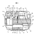
図1は本発明の一実施の形態例に係るドラム式洗濯乾燥機の外観図である。図2は内部の構造を示す側面図、図3は内部の構造を示す平面図(上補強材36の一部を切断して示している)、図4は図2の2点鎖線で切断し矢印A−Aから見た断面図、図5は洗濯槽底部の断面図、図6は図6中2点鎖線で切断し矢印B−Bからみた断面図である。
FIG. 1 is an external view of a drum type washing / drying machine according to an embodiment of the present invention. 2 is a side view showing the internal structure, FIG. 3 is a plan view showing the internal structure (a part of the upper reinforcing
1は、外郭を構成する筐体である。筐体1は、ベース1hの上に取り付けられており、左右の側板1a,1b,前面カバー1c,背面カバー1d,上面カバー1e,下部前面カバー1fで構成されている。左右の側板1a,1bは、コの字型の上補強材36,前補強材37,後補強材(図示せず)で結合しており、ベース1hを含めて箱状の筐体1を形成し、筐体として十分な強度を有している。
9は、前面カバー1cの略中央に設けた洗濯物を出し入れするための投入口を塞ぐドアで、前補強材37に設けたヒンジ9cで開閉可能に支持されている。ドア開放ボタン9dを押すことロック機構(図示せず)が外れて開き、ドアを前面カバー1cに押し付けることでロックされて閉じる。前補強材37は、後述する外槽の開口部と同心に、洗濯物を出し入れするための円形の開口部を有している。
6は、筐体1の上部中央に設けた操作パネルで、電源スイッチ39,操作ボタン12,13,表示器14を備える。操作パネル6は、筐体1下部に設けた制御装置38に電気的に接続している。
Reference numeral 6 denotes an operation panel provided in the upper center of the
19は、筐体1内の上部左側に設けた上部および前部に開口を有する洗剤容器で、前部開口19bから引き出し式の洗剤トレイ7を装着する。洗剤類を入れる場合は、洗剤トレイ7を図1中2点鎖線で示すように引き出す。洗剤容器19は、筐体1の上補強材36に固定されている。また、洗剤容器19の左側面、やや後方に出水口19aを有している。従って、洗剤容器19底面は出水口19aの位置が最も低くなるようなすり鉢状に形成されている。
洗剤容器19の後ろ側には、給水電磁弁16や風呂水給水ポンプ17,水位センサ34など給水に関連する部品を設けてある。洗剤容器19の上部開口19cには、給水電磁弁16を取り付けた給水ユニット15を備える。上面カバー1eには、水道栓からの給水ホース接続口16a,風呂の残り湯の吸水ホース接続口17aが設けてある。
On the back side of the
3は、回転可能に支持された円筒状の洗濯兼脱水槽であり、その外周壁および底壁に通水および通風のための多数の貫通孔3bを有し、前側端面に洗濯物を出し入れするための開口部3aを設けてある。開口部3aの外側には洗濯兼脱水槽3と一体の流体バランサ
3cを備えている。また、洗濯兼脱水槽3の回転中心軸は、水平または開口部側が高くなるように傾斜している。
A cylindrical washing / dehydrating
2は、円筒状の外槽であり、洗濯兼脱水槽3を同軸上に内包し、前面は開口し、後側端面の外側中央にモータ4を取り付ける。モータ4の回転軸は、外槽2を貫通し、洗濯兼脱水槽3と結合している。前面の開口部には外槽カバー2dを設け、外槽内への貯水を可能としている。外槽4は、下側をベース1hに固定されたダンパ5で防振支持されている。また、外槽4の上側は上部補強部材36に取り付けた補助ばね33で支持されており、外槽4の前後方向へ倒れを防ぐ。外槽カバー4dの前側中央には、洗濯物を出し入れするための開口部2cを有している。本開口部2cと前補強材37に設けた開口部は、ゴム製のベローズ10で接続しており、ドア9を閉じることで外槽2を水封する。
外槽2の左側外側面後部には、外槽2内へ水や洗剤類を供給する給水口2aを設けてある。給水口2aと洗剤容器19の出水口19aは、ゴム製の蛇腹管A20で接続する。給水口2aは蒸気弁11を内蔵している。
A
図7は蒸気弁11の詳細を示す断面図である。蒸気弁11は、略円筒形状で、外径部に外槽2の給水口2aに装着するための庇部を有している。内径部は上流側内径φd1より下流側内径φd2の方が大きく、両内径部はリング状の傾斜面11aで接続されている。傾斜面11aは洗濯兼脱水槽3側が高く外槽2の外周側が低くなるように形成している。傾斜面11aの最上部には内側に突出した突出部11bを有しており、突出部11bには複数本のピン11cを設けてある。傾斜面11aには、傾斜面11aを塞ぐよう、楕円状のシート11dを装着している。シート11dの長軸側端部にはピン11cと同じ配置の孔を設けてあり、この孔をピン11cに入れ加締めることでシート11dを傾斜面11aに固定する。従って、シート11dは片持ち支持で傾斜面11aに固定されている。
FIG. 7 is a cross-sectional view showing details of the
シート11dは、可撓性のゴムや合成樹脂製である。シート11dに上側から力が作用すると(給水時)、図7中2点鎖線で示すように変形し蒸気弁11は開となり水が流れる。一方、乾燥時のように外槽内の圧力が洗剤容器19内の圧力(大気圧)より高いとシート11dに下側から力が作用し、シート11dは傾斜面11cに押しつけられ、蒸気弁
11は閉となる。
The
外槽2の底面には、凹状の窪み部2aが軸方向に設けてある。窪み部2aの底面は、前側から後側に下がる傾斜面になっており、窪み部2aの後ろ側最下部に排水口21が設けてある。排水口21には排水ホース22を接続する。窪み部2aの前側には底部循環水の流入口18が設けてある。また、窪み部2aの上部には、窪み部2aの幅の略半分を覆うように外槽2外周壁の内周面から連続する隔壁2bを有している。隔壁2bは洗濯兼脱水槽3の脱水時の回転方向に対して対抗する方向に設ける。排水口21及び流入口18は、窪み部2aの幅方向の中心から洗濯兼脱水槽3の回転方向にずれた位置に設置してある。このため、排水口21と流入口18の上部には隔壁2bがある。
On the bottom surface of the
窪み部2aは、脱水時に洗濯兼脱水槽3の回転による遠心力で、貫通孔3bから外槽2内周面に出て、洗濯兼脱水槽3の回転方向と同一方向に流れる水を受け止め、排水口21へ導く。隔壁2bは、窪み部2aへ入った水が再び外槽2内へ循環しないように堰き止める作用を有する。
The
外槽9の後部端面の最下部にはエアトラップ36が設けてあり、チューブ35で水位センサ34と接続し、外槽2内の水位を検出する。
An
外槽2とベース1hとのすき間には、循環ポンプ24,フィルタケース23,排水弁
25を設けてある。フィルタケース23は、前側に開口部を有する円筒状で、内部に着脱可能なフィルタ23cが装着されており、洗濯水中の異物や糸くずを捕集する。フィルタケース23は、下部前面カバー1fに設けた扉1gを開けることで、取っ手23dを回すことでフィルタ23cを容易に着脱できるよう、前側が高くなるように傾斜している。循環ポンプ24を中心とする洗濯水の循環系に関しては後で詳しく述べる。
A
8は、筐体1の上部右側に設けた引き出し式の乾燥フィルタで、フィルタを掃除する時にメッシュ式のフィルタ8aを取り出す。乾燥フィルタ8には、乾燥ダクト29が接続している。乾燥ダクト29は、筐体1の背面内側に設置してあり、外槽2の後部端面下方に設けた吸気口にゴム製の蛇腹管B29aで接続している。乾燥ダクト29内には、水冷除湿機構(図示せず)を内蔵しており、給水電磁弁16dから給水ホース32で、水冷除湿機構へ冷却水を供給する。
8 is a drawer-type dry filter provided on the upper right side of the
28は、乾燥フィルタ8の後ろ側に設けた送風ファンで、吸気口を乾燥フィルタ8に、吐出口をヒータ(図示せず)が内蔵された温風ダクト31に接続する。温風ダクト31は、ゴム製の蛇腹管(図示せず)を介して、外槽2の前部開口部に接続している。
乾燥運転時に送風ファン28を運転し、ヒータに通電すると、洗濯兼脱水槽3内に温風が吹き込み、洗濯物を温め水分が蒸発する。高温多湿となった空気は、乾燥ダクト29に吸い込まれ、水冷除湿機構を流下する冷却水で冷却除湿されて乾いた低温空気となり、フィルタ8aを通りヒータで再度加熱され、洗濯兼脱水槽3内に吹き込むように循環する。
When the
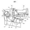
循環ポンプ24を中心とした洗濯水の循環系について図2及び図8から図11を用いて説明する。図8は循環ポンプ及び配管を示す斜視図、図9は循環ポンプ,フィルタケースの配管接続部を示す斜視図、図10は循環ポンプケーシングの内部を示す斜視図、図11は循環ポンプのランナーとモータを示す斜視図である。
The washing water circulation system centering on the
フィルタケース23底部奥側には、入水口23a,出水口23b,循環ポンプ24の吸入口43が設けてある。外槽2の排水口21と入水口23aとはホース22で、排水弁
25と出水口23bとはホース49で繋がっている。また、排水弁25には排水ホース
26が接続しており、機外へ洗濯水を排水する。
A
循環ポンプ24は、ケーシング42,ランナー46,循環ポンプモータ47で構成されている。ケーシング42はフィルタケース23と一体で形成されており、ケーシング42の側壁42aの中央部に吸入口43がある。ケーシング内周面には吐出ポートA44aと吐出ポートB45aが隔壁46a,46bを挟んで開口しており、それぞれ吐出口A44と吐出口B45が接続している。隔壁46a,46bはケーシング42の内側に突出した山形形状で、奥側はケーシング側壁42aに接し、軸方向の長さは下で述べる羽根の高さと略同一である。また、隔壁46a,46bの吐出ポート側壁面はほぼ垂直になっている。この実施例では、隔壁46aと46bは2つの山形形状になっているが、中央の谷部を有しない台形状の山形形状でもかまわない。
The
循環ポンプモータ47の軸にはランナー46が取り付けられている。ランナー46には十字型の羽根46a,46bが形成されている。羽根46aは中心部が羽根ボス46cと略同一高さで外周部を低くし、羽根46bは羽根46aよりも高さを低くしてある。こうすることで、羽根46aと羽根46bを跨ぐように糸屑が流入しても、羽根46a高さが外周に向かうほど低くなっているため、遠心力で糸屑が容易にはね飛ばされ、羽根に糸屑がからむことを防止できる。
A
ランナー正面から見てランナー46が左回転すると(以後、正回転)、吸入口43から流入した水は、ランナー46の遠心力によるポンプ作用でケーシング42の内周壁に向かい押し出されケーシング42内を右回転しながら流れるが、ケーシングと羽根との径方向すき間が狭くなる隔壁46aにぶつかり流れ方向を変え吐出ポートA44aから流れ出る。ランナー46が左回転(以後、逆回転)すると、水は隔壁46bにぶつかり吐出ポートB45aから流れ出る。このように、ポンプの回転方向を変えることで、特別な流路の切り換え機構を用いずにポンプの吐出方向を変えることが出来る。
When the
ケーシング42の外周部には複数個の突起部42bがあり、突起部42bを循環ポンプベース48のリング状のすき間48bに差し込み、ケーシング42を回転させ、突起部
42bを循環ポンプベース48に設けたロック部48aで抑えることで、ケーシングを固定する。
The outer periphery of the
吐出口A44は、蛇腹管C41を介して外槽カバー2dの前側外周壁に取り付けた循環ホース27に繋がっている。循環ホース27は、外槽カバー2d上側に設けたノズル27aに接続している。ノズル27aは、薄膜状に水を水平方向に広げる形状(例えばスリット状)になっており、洗濯水を洗濯兼脱水槽3内に向かって散水する。
The discharge port A44 is connected to the
吐出口B45は、蛇腹管D40を介して外槽2底部の窪み部2aに設けた流入口18に繋がっている。
The discharge port B45 is connected to the
排水弁25を閉じた状態で循環ポンプ24を正回転すると、外槽2内の洗濯水は排水口21からホース22を通りフィルタ23cで異物を除去され、循環ポンプ24に入り、吐出口A44からはき出され、循環ホース27を通りノズル27aから洗濯兼脱水槽3内に散水される。
When the
循環ポンプ24を逆回転すると、外槽2内の洗濯水は排水口21からホース22を通りフィルタ23cで異物を除去され、循環ポンプ24に入り、吐出口B45からはき出され、流入口18から外槽2内に戻るように循環する(図5中の太い矢印で示す流れ)。
When the
排水弁25を開くと、外槽2内の洗濯水は、フィルタ23cを通りホース45から排水弁25を経て、排水ホース22から機外へ排水される。
When the
図12は、洗濯乾燥機の制御装置38のブロック図である。50はマイクロコンピュータで、各スイッチ13,13aに接続される操作ボタン入力回路51や水位センサ34,温度センサ52,振動センサ53と接続され、使用者のボタン操作や洗濯工程,乾燥工程での各種情報信号を受ける。マイクロコンピュータ50からの出力は、駆動回路54に接続され、給水電磁弁16,排水弁25,循環ポンプモータ47,モータ4,送風ファン
28,ヒータ55などに接続され、これらの開閉や回転,通電を制御する。また、使用者に洗濯機の動作状態を知らせるための7セグメント発光ダイオード表示器14や発光ダイオード56,ブザー57に接続される。
FIG. 12 is a block diagram of the
前記マイクロコンピュータ50は、電源スイッチ39が押されて電源が投入されると起動し、図13および図14に示すような洗濯および乾燥の基本的な制御処理プログラムを実行する。
The
ステップS101
洗濯乾燥機の状態確認および初期設定を行う。
Step S101
Check the condition of the washer / dryer and make initial settings.
ステップS102
操作パネル6の表示器14を点灯表示し、操作ボタンスイッチ13からの指示入力に従って洗濯コースを設定する。指示入力がない状態では、標準の洗濯コースまたは前回実施の洗濯コースを自動的に設定する。
Step S102
The
ステップS103
操作パネル6のスタートスイッチ12からの指示入力を監視して処理を分岐する。
Step S103
The process branches after monitoring the instruction input from the
ステップS104
洗剤量検出処理を実行する。この洗剤量検出は、洗い水を給水する前の乾布状態において、洗濯兼脱水槽3を一方向に回転させたときに、規定の回転数1から規定の回転数2まで増速する間のモータ4の駆動電流積算値に基づいて洗濯物の布量を検出するようにモータ4を制御し、検出した布量に基づいて洗剤の適量(洗剤量)を求めることによって行う。洗剤量は、予め設定した布量と洗剤量の対照テーブルを参照することによって求める。
Step S104
The detergent amount detection process is executed. This detergent amount detection is performed by a motor that increases speed from a specified
また、この検出結果(布量)に基づいて洗濯時間を求めて設定する。布量検出が行われない時には、標準の洗濯時間を設定する。 Further, the washing time is obtained and set based on the detection result (cloth amount). When the amount of cloth is not detected, a standard washing time is set.
ステップS105
求めた洗剤量を操作パネル8の表示器25に表示する。
Step S105
The determined amount of detergent is displayed on the
ステップS106
使用者は、洗剤トレイ7を引き出し、表示された量の粉末洗剤を洗剤トレイ7へ投入する。マイクロコンピュータ50は、使用者が洗剤を洗剤トレイ7へ入れるのに必要な時間(例えば1分間)待機した後、給水電磁弁16bを開き、洗剤トレイ7へ散水し、粉末洗剤を洗剤容器19内へ流すよう給水を実行する。粉末洗剤は、給水の水と共に洗剤容器
19の出水口19aから蛇腹管A20を通り、外槽2の給水口2aから外槽2の底部窪み部2aに流下する。
Step S106
The user pulls out the
給水口2aで水は、流れの向きを蒸気弁11のシート11dで外槽2の内周面に向かうよう整流され(図4および図7の矢印で示すように流れる)、外槽2の内周面に沿って流れるため、水や洗剤が洗濯兼脱水槽3内に流れ込むことはない。このようにシート11dの整流作用で、未溶解の粉末洗剤が直接洗濯物に触れることによる色落ちや色むらの発生を防止できる。
Water is rectified in the
また、洗剤が液体洗剤の場合は、給水電磁弁16bが開く前に高濃度の液体洗剤が外槽2内に流下するのを防ぐために、洗剤トレイ7に液体洗剤用の部屋を設け、ここに一旦溜めておき、給水電磁弁16bからの給水で希釈しながら外槽4へ供給するのが一般的である。本実施例では、シート11dの整流作用で洗剤が直接洗濯兼脱水槽3内へ流入することがないため、液体洗剤用の部屋を洗剤トレイに設ける必要がなく、洗剤トレイ7の構造を簡単化でき、低コスト化を図ることができる。
When the detergent is a liquid detergent, a liquid detergent room is provided in the
ステップS107
洗剤溶かし水位まで給水したら給水を停止する。この実施例では、給水量を洗剤量(布量)に応じて制御するようにした。具体的には、洗剤量が17グラムから44グラムであり、水量は約3リットルから約7リットルとなる。給水量の制御は、水位センサ34により行う。この水量は、この後の洗剤溶かし工程(ステップS108)で生成される洗い水の洗剤濃度が、最大で10倍となるように設定している。ここで、洗剤濃度は洗剤メーカの指定標準濃度(一般の粉末合成洗剤では水30リットルに洗剤20グラムを溶かしたときの濃度)を1倍と定義している。洗剤濃度を最大で10倍とした理由は、次による。
Step S107
Stop water supply when the detergent is dissolved and water is supplied. In this embodiment, the amount of water supply is controlled according to the amount of detergent (cloth amount). Specifically, the amount of detergent is 17 grams to 44 grams, and the amount of water is about 3 liters to about 7 liters. The water supply amount is controlled by the
一般の粉末合成洗剤には、界面活性剤のほか、助剤として酵素やアルカリ剤,水軟化剤,蛍光増白剤などが含まれている。洗剤濃度が高すぎると、蛍光増白剤による衣類の色むら(紫外線を当てると特に顕著)が発生するという問題がある。この色むらを目立たなくするには、洗剤濃度を10倍以下に抑える必要がある。 In general powder synthetic detergents, in addition to surfactants, enzymes, alkali agents, water softeners, fluorescent brighteners and the like are included as auxiliary agents. If the detergent concentration is too high, there is a problem that uneven color of clothes (particularly noticeable when exposed to ultraviolet rays) due to the fluorescent brightener. In order to make this uneven color inconspicuous, it is necessary to suppress the detergent concentration to 10 times or less.
ステップS108
循環ポンプモータ47に通電し、循環ポンプ24を逆回転させ洗剤溶かしを実行する。外槽2の底部及び窪み部2bに溜まっている水と洗剤は、排水口21からホース22,フィルタ23cを通り吸入口43からケーシング42内に入る。そして、吐出口B45からはき出され、蛇腹管D40を通り流入口18から窪み部2aに戻るように循環する。洗剤は、ランナー46の羽根46a,46bで攪拌され溶解していき、高洗剤濃度の洗い水が生成される。洗剤溶かしの時間は1分間から2分間である。
Step S108
The
流入口18から窪み部2aへ流れ出る時の流れ方向は上向きであるが、隔壁2bに当たり、流れ方向を排水口21側に変える(図5中の太い矢印)。このため、洗剤溶かし初期段階で未溶解の洗剤が多く含まれる水が循環しているときでも、未溶解の洗剤が洗濯槽3内に直接流入することを防ぐことができる。しかし、隔壁2bに当たった水の一部が外槽カバー2d側に流れることがある。外槽カバー2b側で流れの滞留部分があると、この部分に未溶解洗剤が堆積する恐れがある。
The flow direction when flowing out from the
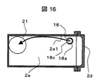
そこで、窪み部2aへ戻った水を確実に排水口21側へ向かうようにする整流部材を設けてもよい。図15は流入口18に整流部材18aを設けた外槽2底部の断面図である。図16は図15の2点鎖線C−C線で切断し矢印方向から見た窪み部2aである。整流部材18aは円筒形で窪み部2a内に突出するように設ける。上部は蓋18bで塞がれており、円筒面には排水口側に向かう開口部18bを有している。開口部18cは、円筒面の約半分を切り欠いて形成している。また、開口部18cの開口方向は、窪み部2aの長手方向もしくは少し窪み部2aの側壁2a1側に向いている。流入口18から出た水は、太い矢印で示したように整流部材18aの開口部18cから排水口21に向かい流れる。外槽カバー2d側には整流部材18aの円筒面があるため、外槽カバー2d側に水が流れることはなく、未溶解洗剤が堆積することはない。
Therefore, a rectifying member may be provided to ensure that the water returned to the
また、フィルタ23cは格子状のフィルタであり、通過する未溶解の粉末洗剤が堆積することはない。
Moreover, the
洗剤溶かし中(循環ポンプが逆回転中)、隔壁46bの作用で吐出ポートA44a部の圧力は吐出ポートB45aの圧力より大幅に低くなっているため、水や未溶解の洗剤がノズル27aから洗濯兼脱水槽3内に出ることはない。しかし、蛇腹管C41や循環ホース27の途中まで未溶解の洗剤が入り込むことがある。そこで、洗剤溶かし中に循環ポンプ24を一時停止するようにする。循環ポンプ24が停止すると、蛇腹管C41や循環ホース27内に浸入した未溶解洗剤はケーシング42内に戻る。そして、循環ポンプ24を再度運転することで未溶解洗剤を無くすことができる。循環ポンプ24の一時停止は、洗剤溶かし中に3回から4回実施する。また、循環ポンプ24の停止時間は、1秒間あれば十分である。
During the dissolution of the detergent (when the circulation pump is rotating in reverse), the pressure of the discharge port A44a is significantly lower than the pressure of the discharge port B45a due to the action of the
洗剤溶かし中の水量は、上記のように3リットルから7リットルである。この実施例のドラム式洗濯乾燥機では、この水量を給水すると水位は洗濯兼脱水槽3内に入る。このため、洗剤溶かし中に洗濯物に高い洗剤濃度の洗い水が染み込んでいく。このとき、モータ4に通電し洗濯兼脱水槽3を低速回転(毎分30から40回転)させることで、洗い水を洗濯物に均等に浸透させるようにしてもよい。
The amount of water in the detergent melt is 3 to 7 liters as described above. In the drum type washing and drying machine of this embodiment, the water level enters the washing and
洗剤濃度が約1倍を超えると、洗剤に含まれる界面活性剤がミセルと呼ばれる集合体を形成するようになる。ミセルは、界面活性剤の疎水基が中心を向き、親水基が外側を向いた球状体で、その直径は10nm程度である。疎水基に囲まれたミセルの中心部は、可溶化作用が大きく、油性物質や脂質を溶解する能力が非常に高い。また、ミセルの数は、洗剤濃度が高いほど多くなる。 When the detergent concentration exceeds about 1 times, the surfactant contained in the detergent forms an aggregate called micelle. The micelle is a spherical body in which the hydrophobic group of the surfactant faces the center and the hydrophilic group faces the outside, and its diameter is about 10 nm. The central part of the micelle surrounded by the hydrophobic group has a large solubilizing action and has a very high ability to dissolve oily substances and lipids. Moreover, the number of micelles increases as the detergent concentration increases.
ステップS109
前洗いを実行する。この前洗いは、洗濯兼脱水槽3を正逆回転(毎分35回転から45回転)させながら、循環ポンプモータ47に循環ポンプ24を正回転することによって外槽3の底部の洗い水をノズル27aから洗濯物上に降り掛ける。洗濯物は、洗濯兼脱水槽3の内周壁面に設けられたリフターで持ち上げられ、落下する運動を繰り返す。洗濯兼脱水槽3の回転と循環ポンプ24の運転を間欠的に行い、洗濯兼脱水槽3と循環ポンプ24の停止期間中に水位センサ34の検出信号を参照しながら給水電磁弁16b開いて水位が設定水位を越えないように補給水する。この運転を複数回繰り返すことによって洗濯物にむらなく洗い水を染み込ませるように行う。
Step S109
Perform pre-washing. In this pre-washing, washing water at the bottom of the
第1回目の洗濯兼脱水槽3の正逆回転時には、洗剤濃度が約10倍の洗い水が洗濯物に降り掛かって該洗濯物内に浸透していく。高濃度の洗い水は、ノズル27aから薄い膜状に広がりながら散布されるため、洗剤の浸透作用で洗濯物にむらなく浸透する。洗濯物が多い場合、ノズル27aからの洗い水は洗濯兼脱水槽3の外周に近い部分の洗濯物へ行き渡りにくいが、ステップS108の洗剤溶かし中に洗濯兼脱水槽3を回転させることで、洗濯兼脱水槽3の外周側から洗濯物に洗い水が浸透するため、洗濯物全体に洗い水が浸透する。
At the time of forward and reverse rotation of the first washing / dehydrating
洗濯物に浸透した高濃度の洗い水中には上述のミセルが多く含まれているため、油汚れを溶解し、洗濯物から汚れが浮き上がらせる効果が非常に大きく、高い洗浄力が得られる。 Since the above-described micelles are contained in the high-concentration washing water that has permeated into the laundry, the effect of dissolving the oil stain and raising the stain from the laundry is very large, and a high detergency is obtained.
ノズル27aは、外槽カバー2dの前側上部にある。そこで、循環ポンプ24の回転数を増減させて流量を変化させることで、シャワーの到達距離が変化させ、洗濯物へより均一に散布することができる。すなわち、回転数を低くし流量を少なくすると、シャワーを洗濯兼脱水槽3の手前側にある洗濯物に散布でき、回転数を高くして流量を増やすと、シャワーを洗濯兼脱水槽3の奥側にある洗濯物に散布できる。
The
補給水を繰り返すことによって洗濯物に降り掛かる洗い水の洗剤濃度が低下して行き、前洗い終了段階では、標準濃度の2倍程度となる。 By repeating the replenishing water, the detergent concentration of the washing water falling on the laundry decreases, and at the end of the pre-washing, it becomes about twice the standard concentration.
ステップS110
本洗いを実行する。洗濯兼脱水槽3を正逆回転(毎分35回転から45回転)させながら循環ポンプ24を正回転させて外槽3の底部に溜まった洗い水をノズル27aから洗濯物に降り掛ける。
Step S110
Perform the main wash. While the washing and
最後に、洗濯水循環ポンプ24の運転を停止して洗い水の循環を止め、洗濯兼脱水槽3を短周期で正逆回転させながら、洗濯物をほぐす運転を実行本洗い時間を終了させるようにする。
Finally, the operation of the washing
ステップS111
第1回目の溜めすすぎを実行する。この溜めすすぎでは、先ず、排水弁25を開き外槽3内の水を排水し、排水が完了したことを水位センサ34で検知した後に、洗濯兼脱水槽3を一方向(この実施例では、洗濯機の正面から見て反時計方向)に回転させて洗濯物に含まれている洗い水を遠心脱水する。
Step S111
The first rinsing rinse is performed. In this rinsing, first, the
その後、給水電磁弁16bを開き、水道水を洗剤容器19に供給し、給水口2aから設定水位になるまで外槽3底部に給水する。次に、本洗いと同様、洗濯兼脱水槽3を反転回転(毎分35回転から45回転)させながら、循環ポンプ24を正回転して、外槽3の底部に溜まったすすぎ水をノズル27aから洗濯物に振り掛けるように循環し、すすぎを実行する。
Thereafter, the water supply
次に、洗濯兼脱水槽3の回転と循環ポンプ24の運転を停止した状態で外槽3の底部に溜まるすすぎ水の水位を水位センサ34で検出しながら水位が設定水位を越えないように補給水を行う。
Next, while the rotation of the washing and
次に、洗濯兼脱水槽3を反転回転(毎分35回転から45回転)させながら、循環ポンプ24正回転して、外槽3の底部に溜まったすすぎ水をノズル27aから洗濯物に振り掛けるように循環し、すすぎを実行する。ノズル27aから出るすすぎ水は、薄膜状となって洗濯物に散布されるため、洗濯物にむらなく掛かり、洗濯物に含まれる洗剤成分を効率よく希釈でき、すすぎ性能を高くできる。
Next, while the washing and
その後、電動循環ポンプ24を停止してすすぎ水の循環を止めた状態で、洗濯兼脱水槽3を短周期で正逆回転させ、ほぐし運転を行う。
Thereafter, in a state where the
ステップS112
第2回目の溜めすすぎを実行する。この第2回目の溜めすすぎは、柔軟仕上げ剤給水電磁弁16cを開いて洗剤トレイ7の柔軟仕上げ剤投入室に給水することによって、柔軟仕上げ剤投入室内の柔軟仕上げ剤を外槽3の底部に導入する制御を付加する。それ以外の動作は、第1回目の溜めすすぎと同様に行う。
Step S112
Perform a second rinsing rinse. In the second rinsing, the soft finish agent water
ステップS113
最終脱水処理を実行する。最終脱水は、排水弁25を開放としたままの状態で洗濯兼脱水槽3を一方向(この実施例では、洗濯機の正面から見て反時計方向)に高速回転させるようにモータ4を運転して洗濯兼脱水槽3内の洗濯物を遠心脱水するように行う。この最終脱水の運転時間は、所望の脱水率が得られる時間に設定する。
Step S113
Perform final dehydration. In final dehydration, the
ステップS114
洗濯乾燥コースが設定されているかどうかを確認して処理を分岐する。
Step S114
The process branches after confirming whether the washing / drying course is set.
ステップS115
洗濯乾燥コースが設定されている場合は、乾燥を実行する。この乾燥は、排水弁25を開放したままの状態として、洗濯工程と同様に、洗濯兼脱水槽3を正逆回転させながら、乾燥ダクト29の途中に設けた送風ファン28を運転することによって外槽3内の空気を乾燥ダクト29内に吸い出し、この乾燥ダクト29内を通過するときに該乾燥ダクト29内に設置した除湿機構から流れ落ちる冷却水(冷却水給水電磁弁をひらき供給する)に触れさせて冷却除湿した後にリントフィルタ8を通して糸屑を捕集し、ヒータによって加熱した後に温風吹き出し口から洗濯兼脱水槽3内に吹き込むことにより行う。
Step S115
When the washing / drying course is set, the drying is executed. This drying is performed by operating the
乾燥は、温度センサにより温風の温度を監視しながら実行し、温度変化の割合が所定の値になったときに終了する。 Drying is performed while monitoring the temperature of the hot air with a temperature sensor, and ends when the rate of temperature change reaches a predetermined value.
このように構成した洗濯乾燥機は、次のような作用効果が得られる。 The washing and drying machine configured as described above has the following operational effects.
洗剤量(布量)検知手段で検出した洗濯物の量(洗剤の量)に応じた水量の水を洗剤と一緒に外槽の底部に溜まるように給水し、循環ポンプを逆回転することで、水を外槽底部から循環ポンプを経て外槽底部へ戻るように循環しながら洗剤を溶かし高洗剤濃度の洗い水を生成する。このときの洗剤濃度は、洗濯物の量によらずほぼ一定にできる。そして、循環ポンプを正逆転することで、高洗剤濃度の洗い水を外槽上部に導き、ノズルで薄膜状に広げて洗濯物に降り掛け、洗濯物にむらなく浸透させる。このように、循環ポンプの回転方向を変えることで、洗剤を溶かし高洗剤濃度の洗い水の生成と、生成した洗い水の循環散水という2つの動作を1台の循環ポンプで実現でき、低コスト化や洗い水の循環経路の簡単化ができる。 The amount of water corresponding to the amount of laundry (the amount of detergent) detected by the detergent amount (cloth amount) detection means is supplied to the bottom of the outer tub together with the detergent, and the circulation pump is rotated in the reverse direction. The detergent is dissolved while the water is circulated from the bottom of the outer tank to the bottom of the outer tank via a circulation pump, thereby generating washing water having a high detergent concentration. The detergent concentration at this time can be made almost constant regardless of the amount of laundry. Then, by rotating the circulation pump forward and backward, the washing water having a high detergent concentration is guided to the upper part of the outer tub, spreads in a thin film shape with a nozzle, falls on the laundry, and permeates the laundry evenly. In this way, by changing the direction of rotation of the circulation pump, the two operations of dissolving detergent and generating washing water with high detergent concentration and circulating watering of the generated washing water can be realized with a single circulation pump. And the circulation route of washing water can be simplified.
また、洗剤溶かし中に洗濯兼脱水槽を低速回転することで、生成した洗い水を洗濯兼脱水槽の外周側から洗濯物に浸透させ、次に、循環ポンプで洗濯兼脱水槽の前側から散水することで、より一層洗濯物へ洗い水を均一に行き渡らせることができる。高濃度洗剤液の浸透作用や界面活性剤のミセルによる油汚れの可溶化作用などの化学的な洗浄力により洗濯物から汚れを浮き上がらせる。その後、水を補給し、洗い水を洗濯物に降り掛けるように循環させながら洗濯兼脱水槽を正逆回転させて洗濯物をたたき洗いすることで、洗濯物から浮き上がっていた汚れが洗濯物から離脱し、高い洗浄効率を得ることができる。 In addition, by rotating the washing / dehydrating tub at a low speed while dissolving the detergent, the generated washing water penetrates into the laundry from the outer peripheral side of the washing / dehydrating tub, and then water is sprayed from the front side of the washing / dehydrating tub with a circulation pump. By doing so, the washing water can be evenly distributed to the laundry. The stains are lifted from the laundry by chemical detergency such as penetration of high-concentration detergent solution and solubilization of oil stains by micelles of surfactant. Then, replenish the water and circulate the washing water so that it falls on the laundry. It can be removed and high cleaning efficiency can be obtained.
さらに、洗剤溶かし中に循環ポンプの回転を一旦止め、再度運転することを繰り返すことで、配管中に入り込む未溶解洗剤を無くすことができる。 Furthermore, the undissolved detergent that enters the pipe can be eliminated by temporarily stopping the rotation of the circulation pump while dissolving the detergent and repeating the operation.
1 筐体
2 外槽
2a 窪み部
3 洗濯兼脱水槽
4 モータ
6 操作パネル
7 洗剤トレイ
9 ドア
11 蒸気弁
16 給水電磁弁
18 流入口
19 洗剤容器
19a 出水口
20,40,41 蛇腹管
21 排水口
23 フィルタケース
24 循環ポンプ
38 制御装置
42 ケーシング
43 吸入口
44,45 吐出口
44a,45a 吐出ポート
46a,46b 隔壁
46 ランナー
46a,46b 羽根
DESCRIPTION OF
Claims (13)
前記洗濯水循環機構は、循環ポンプと該循環ポンプと前記外槽とを接続する流路とで構成され、該流路は前記外槽底部から前記循環ポンプへ至る第1の流路と、前記循環ポンプから前記外槽底部へ至る第2の流路と、前記循環ポンプから前記外槽上部へ至る第3の流路とで構成され、
前記第2の流路と前記第3の流路とを切り替える手段を備え
洗剤液を生成する洗剤溶解工程では、前記外槽底部に供給された水と洗剤を前記第1の流路から前記第2の流路を経て前記外槽底部へ戻るように循環させることを特徴とする洗濯機。 An inner tub that is a washing and dewatering tub provided so that the rotation center axis is horizontal or can be rotated so that the opening side is high, and a cylindrical shape that encloses the inner tub and is coaxial with the inner tub and stores washing water An outer tub, a driving device that rotationally drives the inner tub, a water supply mechanism that supplies washing water to the outer tub, a washing water circulation mechanism that circulates the washing water stored in the bottom of the outer tub, A drainage mechanism for draining the wash water, a water level detection means for detecting the water level in the outer tub, a cloth amount detection means for detecting the amount of laundry put into the inner tub, the drive mechanism and the water supply mechanism, In a washing machine equipped with a control device for controlling the drainage mechanism and the washing water circulation mechanism,
The washing water circulation mechanism includes a circulation pump and a flow path connecting the circulation pump and the outer tub. The flow path includes a first flow path from the bottom of the outer tub to the circulation pump, and the circulation. A second flow path from the pump to the bottom of the outer tank, and a third flow path from the circulation pump to the top of the outer tank,
In the detergent dissolution step for generating a detergent liquid, the means for switching between the second flow path and the third flow path is provided. The water and detergent supplied to the bottom of the outer tub are transferred from the first flow path to the first flow path. The washing machine is circulated so as to return to the bottom of the outer tub through two flow paths.
前記制御装置は前記循環ポンプの回転方向を変えることで前記第2の流路と前記第3の流路とを切り替えることを特徴とする洗濯機。 In claim 1,
The control device switches the second flow path and the third flow path by changing a rotation direction of the circulation pump.
前記洗濯水循環機構は、循環ポンプと該循環ポンプと前記外槽とを接続する流路とで構成され、該流路は前記外槽底部から前記循環ポンプへ至る第1の流路と、前記循環ポンプから前記外槽底部へ至る第2の流路と、前記循環ポンプから前記外槽上部へ至る第3の流路とで構成され、
前記第2の流路と前記第3の流路とを切り替える手段を備え、
前記外槽は底部に凹状の水受け部を備え、該水受け部に前記第1の流路入口と前記第2の流路出口を接続し、
前記水受け部は上面を略半分覆う隔壁を有し、前記第2の流路の出口を前記隔壁の下部に設けたことを特徴とする洗濯機。 An inner tub which is a washing and dewatering tub provided rotatably in an outer tub for storing washing water, a driving device for rotationally driving the inner tub, a water supply mechanism for supplying washing water to the outer tub, and the outer tub A washing water circulation mechanism for circulating the washing water stored in the bottom, a drainage mechanism for draining the washing water in the outer tub, a water level detecting means for detecting the water level in the outer tub, and the washing put in the inner tub In a washing machine comprising a cloth amount detection means for detecting the amount of an object, and a control device for controlling the drive mechanism, the water supply mechanism, the drainage mechanism, and the washing water circulation mechanism,
The washing water circulation mechanism includes a circulation pump and a flow path connecting the circulation pump and the outer tub. The flow path includes a first flow path from the bottom of the outer tub to the circulation pump, and the circulation. A second flow path from the pump to the bottom of the outer tank, and a third flow path from the circulation pump to the top of the outer tank,
Means for switching between the second flow path and the third flow path;
The outer tub has a concave water receiving portion at the bottom, and the water receiving portion connects the first flow path inlet and the second flow path outlet,
The washing machine according to claim 1, wherein the water receiving portion has a partition wall that substantially covers the upper surface, and an outlet of the second flow path is provided at a lower portion of the partition wall.
前記第1の流路から前記第2の流路を経て前記外槽底部へ戻るように循環し高濃度洗剤液を生成する洗剤溶解工程と、前記ランナーを前記洗剤溶解工程と反対方向に回転するよう前記循環ポンプを制御し前記外槽底部に生成された洗剤液を前記第1の流路から前記第3の流路を経て前記外槽上部から前記洗濯槽内へ散水する洗剤液散水工程とを実行することを特徴とする洗濯機。 The control device according to claim 3, wherein the control device controls the water supply mechanism to supply a predetermined amount of water and detergent to the bottom of the outer tub, and the runner is connected to the second discharge port from the first discharge port. The circulation pump is controlled to rotate toward the outlet, and the water and detergent supplied to the bottom of the outer tub are circulated from the first flow path to the bottom of the outer tub through the second flow path. A detergent dissolution process for producing a high-concentration detergent liquid, and the detergent pump produced at the bottom of the outer tub by controlling the circulation pump to rotate the runner in the opposite direction to the detergent dissolution process from the first flow path A washing machine that performs a detergent liquid sprinkling step of sprinkling water from the upper part of the outer tub into the washing tub through the third flow path.
前記洗濯水循環機構は、循環ポンプと該循環ポンプと前記外槽とを接続する流路とで構成され、該流路は前記外槽底部から前記循環ポンプへ至る第1の流路と、前記循環ポンプから前記外槽底部へ至る第2の流路と、前記循環ポンプから前記外槽上部へ至る第3の流路とで構成され、
前記第2の流路と前記第3の流路とを切り替える手段を備え、
前記循環ポンプはモータとモータ軸に締結したランナーと該ランナーを覆う円筒状のケーシングとで構成され、該ケーシングはモータの反対側端面中央に吸い込み口を備え、前記ケーシングは内周面の内側に突出した隔壁を有し、該隔壁を挟んで第1の吐出口と第2の吐出口とを備え、該第1の吐出口を前記第2の流路に接続し、該第2の吐出口を前記第3の流路に接続し、
前記制御装置は、前記給水機構を制御し規定量の水と洗剤を前記外槽底部へ供給する洗剤供給工程と、前記ランナーが前記第1の吐出口から前記第2の吐出口へ向かって回転するよう前記循環ポンプを制御し前記外槽底部に供給された水と洗剤を前記第1の流路から前記第2の流路を経て前記外槽底部へ戻るように循環し高濃度洗剤液を生成する洗剤溶解工程と、前記ランナーを前記洗剤溶解工程と反対方向に回転するよう前記循環ポンプを制御し前記外槽底部に生成された洗剤液を前記第1の流路から前記第3の流路を経て前記外槽上部から前記洗濯槽内へ散水する洗剤液散水工程とを実行し、
前記制御装置は、前記洗剤溶解工程において前記循環ポンプの回転を一旦停止し再度回転する運転を複数回繰り返すよう制御することを特徴とする洗濯機。 An inner tub which is a washing and dewatering tub provided rotatably in an outer tub for storing washing water, a driving device for rotationally driving the inner tub, a water supply mechanism for supplying washing water to the outer tub, and the outer tub A washing water circulation mechanism for circulating the washing water stored in the bottom, a drainage mechanism for draining the washing water in the outer tub, a water level detecting means for detecting the water level in the outer tub, and the washing put in the inner tub In a washing machine comprising a cloth amount detection means for detecting the amount of an object, and a control device for controlling the drive mechanism, the water supply mechanism, the drainage mechanism, and the washing water circulation mechanism,
The washing water circulation mechanism includes a circulation pump and a flow path connecting the circulation pump and the outer tub. The flow path includes a first flow path from the bottom of the outer tub to the circulation pump, and the circulation. A second flow path from the pump to the bottom of the outer tank, and a third flow path from the circulation pump to the top of the outer tank,
Means for switching between the second flow path and the third flow path;
The circulation pump includes a motor, a runner fastened to the motor shaft, and a cylindrical casing that covers the runner. The casing includes a suction port at the center of the opposite end surface of the motor, and the casing is located on the inner peripheral surface. And a first discharge port and a second discharge port sandwiched between the partition walls, the first discharge port connected to the second flow path, and the second discharge port. To the third flow path,
The control device controls the water supply mechanism to supply a predetermined amount of water and detergent to the bottom of the outer tub, and the runner rotates from the first discharge port toward the second discharge port. The circulation pump is controlled so that the water and detergent supplied to the bottom of the outer tub are circulated from the first flow path to the bottom of the outer tub through the second flow path, and a high concentration detergent solution is circulated. The detergent dissolving process to be generated, and the circulation pump is controlled so as to rotate the runner in the opposite direction to the detergent dissolving process, and the detergent liquid generated at the bottom of the outer tub is transferred from the first flow path to the third flow. Performing a detergent liquid sprinkling step of sprinkling water from the upper part of the outer tub into the washing tub through the road
The said control apparatus is controlled to repeat the driving | operation which stops rotation of the said circulation pump once in the said detergent melt | dissolution process, and rotates again several times.
Priority Applications (2)
| Application Number | Priority Date | Filing Date | Title |
|---|---|---|---|
| JP2006302252A JP4448843B2 (en) | 2006-11-08 | 2006-11-08 | Washing machine |
| CN2007101478504A CN101177861B (en) | 2006-11-08 | 2007-08-31 | Washing machine |
Applications Claiming Priority (1)
| Application Number | Priority Date | Filing Date | Title |
|---|---|---|---|
| JP2006302252A JP4448843B2 (en) | 2006-11-08 | 2006-11-08 | Washing machine |
Publications (3)
| Publication Number | Publication Date |
|---|---|
| JP2008113982A JP2008113982A (en) | 2008-05-22 |
| JP2008113982A5 JP2008113982A5 (en) | 2009-06-18 |
| JP4448843B2 true JP4448843B2 (en) | 2010-04-14 |
Family
ID=39404267
Family Applications (1)
| Application Number | Title | Priority Date | Filing Date |
|---|---|---|---|
| JP2006302252A Active JP4448843B2 (en) | 2006-11-08 | 2006-11-08 | Washing machine |
Country Status (2)
| Country | Link |
|---|---|
| JP (1) | JP4448843B2 (en) |
| CN (1) | CN101177861B (en) |
Families Citing this family (46)
| Publication number | Priority date | Publication date | Assignee | Title |
|---|---|---|---|---|
| JP4877300B2 (en) * | 2008-07-09 | 2012-02-15 | パナソニック株式会社 | Drum washing machine |
| JP4637222B2 (en) * | 2008-09-29 | 2011-02-23 | シャープ株式会社 | Washing machine and mist generating method |
| JP4325734B1 (en) * | 2008-09-29 | 2009-09-02 | パナソニック株式会社 | Drum washing machine |
| JP4905494B2 (en) * | 2009-04-07 | 2012-03-28 | パナソニック株式会社 | Drum washing machine |
| KR101389238B1 (en) | 2009-08-24 | 2014-04-24 | 가부시끼가이샤 도시바 | Drum type washing machine |
| CN101824726B (en) * | 2009-08-27 | 2012-07-04 | 南京乐金熊猫电器有限公司 | Laundry machine |
| JP5452802B2 (en) * | 2010-05-27 | 2014-03-26 | 日立アプライアンス株式会社 | Washing and drying machine |
| JP2012080928A (en) * | 2010-10-07 | 2012-04-26 | Hitachi Appliances Inc | Washing machine and washing and drying machine |
| CN102535089B (en) * | 2010-12-07 | 2014-04-30 | 比亚迪股份有限公司 | Washing and drying integrated machine |
| JP2013052057A (en) * | 2011-09-02 | 2013-03-21 | Panasonic Corp | Drum type washing machine |
| WO2013008362A1 (en) * | 2011-07-08 | 2013-01-17 | パナソニック株式会社 | Drum-type washing machine |
| JP2013052056A (en) * | 2011-09-02 | 2013-03-21 | Panasonic Corp | Drum type washing machine |
| JP2013017556A (en) * | 2011-07-08 | 2013-01-31 | Panasonic Corp | Drum washing machine |
| JP2012130813A (en) * | 2012-04-13 | 2012-07-12 | Panasonic Corp | Washing machine |
| JP2013223551A (en) * | 2012-04-20 | 2013-10-31 | Hitachi Appliances Inc | Washing machine |
| ITTO20120637A1 (en) * | 2012-07-19 | 2014-01-20 | Indesit Co Spa | WASHING MACHINE WITH RECIRCULATION CIRCUIT |
| JP5957698B2 (en) * | 2012-09-06 | 2016-07-27 | パナソニックIpマネジメント株式会社 | Drum washing machine |
| JP6063335B2 (en) * | 2013-04-22 | 2017-01-18 | 日立アプライアンス株式会社 | Drum washing machine |
| JP6040091B2 (en) * | 2013-04-22 | 2016-12-07 | 日立アプライアンス株式会社 | Drum washing machine |
| JP2015062508A (en) * | 2013-09-25 | 2015-04-09 | 日立アプライアンス株式会社 | Drum type washing machine |
| JP6178187B2 (en) * | 2013-09-25 | 2017-08-09 | 日立アプライアンス株式会社 | Drum washing machine |
| JP6131167B2 (en) * | 2013-10-18 | 2017-05-17 | 日立アプライアンス株式会社 | Washing machine |
| JP6153843B2 (en) * | 2013-10-18 | 2017-06-28 | 日立アプライアンス株式会社 | Drum washing machine |
| JP5599932B2 (en) * | 2013-12-27 | 2014-10-01 | 日立アプライアンス株式会社 | Washing and drying machine |
| JP6208638B2 (en) * | 2014-08-18 | 2017-10-04 | 日立アプライアンス株式会社 | Washing machine |
| JP2016043150A (en) * | 2014-08-26 | 2016-04-04 | 日立アプライアンス株式会社 | Washing machine |
| CN106854805B (en) * | 2014-08-18 | 2019-05-03 | 日立空调·家用电器株式会社 | Washing machine |
| CN106048964B (en) * | 2015-04-08 | 2018-04-10 | 日立空调·家用电器株式会社 | Scrubbing-and-drying unit |
| JP6408418B2 (en) * | 2015-04-08 | 2018-10-17 | 日立アプライアンス株式会社 | Washing and drying machine |
| JP6357453B2 (en) * | 2015-08-19 | 2018-07-11 | 日立アプライアンス株式会社 | Washing and drying machine |
| JP6357452B2 (en) * | 2015-08-19 | 2018-07-11 | 日立アプライアンス株式会社 | Washing and drying machine |
| JP6398085B2 (en) * | 2015-10-13 | 2018-10-03 | パナソニックIpマネジメント株式会社 | Washing machine |
| JP6553550B2 (en) * | 2016-07-19 | 2019-07-31 | 日立グローバルライフソリューションズ株式会社 | Washing machine |
| JP7128606B2 (en) * | 2016-09-06 | 2022-08-31 | 東芝ライフスタイル株式会社 | washing machine |
| JP6718411B2 (en) * | 2017-06-02 | 2020-07-08 | 東芝ライフスタイル株式会社 | Drum type washing machine |
| JP6840060B2 (en) * | 2017-09-11 | 2021-03-10 | 日立グローバルライフソリューションズ株式会社 | Washing machine |
| CN109811510B (en) * | 2017-11-21 | 2022-07-22 | 青岛海尔洗涤电器有限公司 | Ventilation device of washing machine and washing machine |
| CN108004728A (en) * | 2017-11-28 | 2018-05-08 | 青岛海尔洗衣机有限公司 | The water box and washing machine of a kind of washing machine |
| EP3505667B1 (en) | 2017-12-28 | 2020-08-19 | LG Electronics Inc. | Method for controlling washing machine |
| KR102459589B1 (en) | 2018-01-05 | 2022-10-26 | 엘지전자 주식회사 | Washing machine and method for controlling the washing machine |
| JP7308388B2 (en) | 2018-02-21 | 2023-07-14 | パナソニックIpマネジメント株式会社 | Centrifugal separator and washing machine equipped with the centrifugal separator |
| WO2019210974A1 (en) * | 2018-05-04 | 2019-11-07 | Electrolux Appliances Aktiebolag | A method of operating a laundry washing machine comprising a recirculation circuit |
| CN112041498A (en) * | 2018-05-04 | 2020-12-04 | 伊莱克斯家用电器股份公司 | Washing machine and method for operating a washing machine |
| CN110644199B (en) * | 2018-06-27 | 2021-12-03 | Lg电子株式会社 | Washing machine |
| KR102557579B1 (en) * | 2018-08-23 | 2023-07-20 | 엘지전자 주식회사 | Control method for laundry washing machine |
| JP6732867B2 (en) * | 2018-12-17 | 2020-07-29 | 東芝ライフスタイル株式会社 | Drum type washing machine |
Family Cites Families (3)
| Publication number | Priority date | Publication date | Assignee | Title |
|---|---|---|---|---|
| CN1222653C (en) * | 2002-05-31 | 2005-10-12 | 乐金电子(天津)电器有限公司 | Washing water circulation device of laundry machine |
| JP4074165B2 (en) * | 2002-09-10 | 2008-04-09 | アスモ株式会社 | Pump device and washer device |
| EP1688529A1 (en) * | 2005-01-28 | 2006-08-09 | Electrolux Home Products Corporation N.V. | Washing machine with detergent dispenser |
-
2006
- 2006-11-08 JP JP2006302252A patent/JP4448843B2/en active Active
-
2007
- 2007-08-31 CN CN2007101478504A patent/CN101177861B/en active Active
Also Published As
| Publication number | Publication date |
|---|---|
| CN101177861B (en) | 2010-12-22 |
| JP2008113982A (en) | 2008-05-22 |
| CN101177861A (en) | 2008-05-14 |
Similar Documents
| Publication | Publication Date | Title |
|---|---|---|
| JP4448843B2 (en) | Washing machine | |
| JP2012080928A (en) | Washing machine and washing and drying machine | |
| JP4713392B2 (en) | Washing machine | |
| JP5452802B2 (en) | Washing and drying machine | |
| JP5608603B2 (en) | Washing machine | |
| JP6480796B2 (en) | Washing machine | |
| JP6063335B2 (en) | Drum washing machine | |
| CN109750443B (en) | Washing and drying machine | |
| JP6111175B2 (en) | Drum washing machine | |
| JP2018157958A (en) | Washing machine | |
| JP2015062590A (en) | Drum type washing machine | |
| JP6840060B2 (en) | Washing machine | |
| JP6357453B2 (en) | Washing and drying machine | |
| JP2015119886A (en) | Drum type washing machine | |
| JP6076862B2 (en) | Drum washing machine | |
| JP5589135B1 (en) | Drum washing machine | |
| CN109629168B (en) | Washing and drying machine | |
| JP5599932B2 (en) | Washing and drying machine | |
| JP6357452B2 (en) | Washing and drying machine | |
| JP2017047050A (en) | Washing machine | |
| JP6408418B2 (en) | Washing and drying machine | |
| TWI626351B (en) | Laundry dryer | |
| JP6250500B2 (en) | Drum washing machine | |
| JP2017038755A (en) | Washing and drying machine | |
| JP2017158650A (en) | Washing machine |
Legal Events
| Date | Code | Title | Description |
|---|---|---|---|
| A521 | Request for written amendment filed |
Free format text: JAPANESE INTERMEDIATE CODE: A523 Effective date: 20090327 |
|
| A621 | Written request for application examination |
Free format text: JAPANESE INTERMEDIATE CODE: A621 Effective date: 20090327 |
|
| A871 | Explanation of circumstances concerning accelerated examination |
Free format text: JAPANESE INTERMEDIATE CODE: A871 Effective date: 20090327 |
|
| A521 | Request for written amendment filed |
Free format text: JAPANESE INTERMEDIATE CODE: A523 Effective date: 20090327 |
|
| A975 | Report on accelerated examination |
Free format text: JAPANESE INTERMEDIATE CODE: A971005 Effective date: 20090522 |
|
| A131 | Notification of reasons for refusal |
Free format text: JAPANESE INTERMEDIATE CODE: A131 Effective date: 20090526 |
|
| A521 | Request for written amendment filed |
Free format text: JAPANESE INTERMEDIATE CODE: A523 Effective date: 20090727 |
|
| A131 | Notification of reasons for refusal |
Free format text: JAPANESE INTERMEDIATE CODE: A131 Effective date: 20090825 |
|
| A521 | Request for written amendment filed |
Free format text: JAPANESE INTERMEDIATE CODE: A523 Effective date: 20091026 |
|
| A131 | Notification of reasons for refusal |
Free format text: JAPANESE INTERMEDIATE CODE: A131 Effective date: 20091117 |
|
| A521 | Request for written amendment filed |
Free format text: JAPANESE INTERMEDIATE CODE: A523 Effective date: 20091221 |
|
| TRDD | Decision of grant or rejection written | ||
| A01 | Written decision to grant a patent or to grant a registration (utility model) |
Free format text: JAPANESE INTERMEDIATE CODE: A01 Effective date: 20100119 |
|
| A01 | Written decision to grant a patent or to grant a registration (utility model) |
Free format text: JAPANESE INTERMEDIATE CODE: A01 |
|
| A61 | First payment of annual fees (during grant procedure) |
Free format text: JAPANESE INTERMEDIATE CODE: A61 Effective date: 20100125 |
|
| FPAY | Renewal fee payment (event date is renewal date of database) |
Free format text: PAYMENT UNTIL: 20130129 Year of fee payment: 3 |
|
| R150 | Certificate of patent or registration of utility model |
Ref document number: 4448843 Country of ref document: JP Free format text: JAPANESE INTERMEDIATE CODE: R150 Free format text: JAPANESE INTERMEDIATE CODE: R150 |
|
| S531 | Written request for registration of change of domicile |
Free format text: JAPANESE INTERMEDIATE CODE: R313531 |
|
| S533 | Written request for registration of change of name |
Free format text: JAPANESE INTERMEDIATE CODE: R313533 |
|
| R350 | Written notification of registration of transfer |
Free format text: JAPANESE INTERMEDIATE CODE: R350 |