JP4448019B2 - Toner production method and apparatus for modifying the surface of toner particles - Google Patents
Toner production method and apparatus for modifying the surface of toner particles Download PDFInfo
- Publication number
- JP4448019B2 JP4448019B2 JP2004368728A JP2004368728A JP4448019B2 JP 4448019 B2 JP4448019 B2 JP 4448019B2 JP 2004368728 A JP2004368728 A JP 2004368728A JP 2004368728 A JP2004368728 A JP 2004368728A JP 4448019 B2 JP4448019 B2 JP 4448019B2
- Authority
- JP
- Japan
- Prior art keywords
- particles
- fine powder
- toner
- classification
- rotor
- Prior art date
- Legal status (The legal status is an assumption and is not a legal conclusion. Google has not performed a legal analysis and makes no representation as to the accuracy of the status listed.)
- Active
Links
Images


Description
本発明は、電子写真法、静電記録法、静電印刷の如き画像形成方法に用いられるトナーの製造方法及びトナー粒子の表面を改質するための装置に関する。 The present invention relates to a method for producing toner used in an image forming method such as electrophotography, electrostatic recording, and electrostatic printing, and an apparatus for modifying the surface of toner particles.
一般にトナー粒子の製造方法は粉砕法を用いる方法と重合法を用いる方法とが挙げられる。粉砕法により製造されるトナー粒子は、現状では、重合法に比して製造コストが低いという利点があり、現在においても広く複写機やプリンターに使用されるトナーに使用されている。粉砕法でトナー粒子を製造する場合、結着樹脂、着色剤等を所定量混合し、混合物を溶融混練し、混練物を冷却し、冷却されて固化した混練物を粉砕し、粉砕物を分級して所定の粒度分布を有するトナー粒子を得、得られたトナー粒子に流動性向上剤を外添してトナーを製造している。 In general, toner particles can be produced by a pulverization method or a polymerization method. At present, toner particles produced by the pulverization method have an advantage that the production cost is lower than that of the polymerization method, and even now, they are widely used for toners used in copying machines and printers. When producing toner particles by a pulverization method, a predetermined amount of binder resin, colorant, etc. are mixed, the mixture is melt-kneaded, the kneaded product is cooled, the cooled and solidified kneaded product is pulverized, and the pulverized product is classified. Thus, toner particles having a predetermined particle size distribution are obtained, and a toner is manufactured by externally adding a fluidity improver to the obtained toner particles.
近年複写機及びプリンタには、高画質化、省エネルギー化及び環境対応等が要求されている。これに対して、トナーは、高転写効率を達成し、廃トナーを削減するためにトナー粒子を球形化する方向に技術コンセプトが移行してきている。粉砕法によりこの様な技術コンセプトを達成する為に、機械式粉砕法によるトナー粒子の球形化の方法が提案され(特許文献1参照)、また、熱風によるトナー粒子の球形化の方法が提案されている(特許文献2参照)。しかしながら、機械式粉砕法によるトナー粒子の球形化の方法では十分な球形化が達成できない。また、熱風によるトナー粒子の球形化の方法は、トナー粒子にワックスを含有させた場合においては、ワックスの溶融が開始することでトナー粒子の表面性状を制御することが困難となり、トナー粒子の品質安定性に課題が残る。これに対して、高性能の表面処理及び微粉除去も可能なトナー粒子の表面を改質するための表面改質装置が提案されている(特許文献3参照)。しかしながら、該表面改質装置は、高球形化度を維持した場合には微粉除去効率いわゆる分級収率が低下する傾向、画像かぶり現象が生ずる傾向があることが挙げられる為、その改善が望まれている。 In recent years, copiers and printers are required to have high image quality, energy saving, environmental friendliness, and the like. On the other hand, the technical concept of the toner has been shifted to make the toner particles spherical in order to achieve high transfer efficiency and reduce waste toner. In order to achieve such a technical concept by the pulverization method, a method for spheroidizing toner particles by a mechanical pulverization method is proposed (see Patent Document 1), and a method for sphering toner particles by hot air is proposed. (See Patent Document 2). However, sufficient spheroidization cannot be achieved by the method of spheroidizing toner particles by a mechanical pulverization method. In addition, the method of spheroidizing the toner particles with hot air makes it difficult to control the surface properties of the toner particles when the wax is contained in the toner particles, so that it becomes difficult to control the surface properties of the toner particles. Issues remain in stability. On the other hand, there has been proposed a surface modifying apparatus for modifying the surface of toner particles that can perform high-performance surface treatment and fine powder removal (see Patent Document 3). However, the surface modification device has a tendency to reduce the fine powder removal efficiency, so-called classification yield, and to cause image fogging phenomenon when maintaining a high degree of spheroidization. ing.
本発明の目的は上記課題を解消したトナーの製造方法を提供することにある。 An object of the present invention is to provide a toner production method that solves the above problems.
さらに、本発明の目的は、トナー粒子を高度に球形化でき、且つトナー粒子の収率が高いトナーの製造方法を提供することにある。 Furthermore, an object of the present invention is to provide a method for producing a toner that can highly spheroidize toner particles and has a high yield of toner particles.
また、本発明の目的は、画像にカブリが発生しにくいトナーを効率良く製造するトナーの製造方法を提供することにある。 Another object of the present invention is to provide a toner manufacturing method for efficiently manufacturing a toner that is less likely to cause fog in an image.
また、本発明の目的は、効率良くトナー粒子の表面を改質するための装置を提供することにある。 Another object of the present invention is to provide an apparatus for efficiently modifying the surface of toner particles.
本発明は、トナー粒子を有するトナーの製造方法であり、
少なくとも結着樹脂及び着色剤を含有する組成物を溶融混練する混練工程、
得られた混練物を冷却する冷却工程、
冷却固化物を微粉砕して微粉砕物を得る工程、及び
得られた微粉砕物に含まれる粒子の表面改質をおこなうための表面改質工程と、得られた微粉砕物に含まれる微粉及び超微粉を除去するための分級をおこなう分級工程とを同時に行ってトナー粒子を得る工程を有し、
表面改質工程と分級工程とを同時におこなってトナー粒子を得る工程が、回分式の表面 改質装置を用いて行われ、
該表面改質装置は、
円筒形状の本体ケーシング、
該本体ケーシングに開閉可能に設置された天板、
該微粉砕物を本体ケーシング内に投入する投入部、
該本体ケーシング内に投入された微粉砕物から所定粒径以下の微粉及び超微粉を装置外へ連続的に除去するために所定方向に回転する分級ローターを有する分級手段、
該分級手段によって除去された該微粉及び該超微粉を本体ケーシング外に排出する微粉排出部、
該微粉及び該超微粉が除去された微粉砕物に含まれる粒子を機械式衝撃力を用いて表面改質処理するための、該分級ローターの回転方向と同方向に回転する分散ローターと固定配置されているライナーとを有する表面改質手段、
本体ケーシング内に第一の空間と第二の空間とを形成するための円筒形状の案内手段、及び、
該分散ローターによって表面改質処理が行われたトナー粒子を本体ケーシング外に排出するためのトナー粒子排出部を少なくとも有し、
該本体ケーシングの内壁と円筒形状の該案内手段の外壁との間に設けられた該第一の空間は、該微粉砕物及び表面改質された該粒子を該分級ローターへ導くための空間であり、 該第二の空間は、該微粉及び該超微粉が除去された微粉砕物及び表面改質された該粒子を分散ローターで処理するための空間であり、
該表面改質装置内において、該投入部より本体ケーシング内に投入された微粉砕物を第一の空間に導入し、該分級手段により所定粒径以下の微粉及び超微粉を除去して装置外へ連続的に排出しつつ微粉及び超微粉が除去された微粉砕物を第二の空間へ移動させて、該分散ローターで処理して微粉砕物中の粒子の表面改質処理を行い、再び表面改質された粒子を含む微粉砕物を第一の空間と第二の空間とへ循環させることにより該分級と該表面改質処理とを繰り返し、これにより所定粒径以下の微粉及び超微粉が所定量以下に除去されており且つ表面改質されたトナー粒子を得をうるものであり、
該分散ローターは、該分散ローター上面の外縁部に設置された角型ディスクを含んだ外径Dが120mm以上であり、
該角型ディスクと該ライナーとの最小間隔が、1.0mm乃至3.0mmであり、
該角型ディスクの数nと、該外径Dとが、下記式(1)の関係を満足し、
44.9≦πD/n≦125.6(mm) (1)
該分散ローターの上面に設置されている角型のディスクの高さをHとし、該分散ローターの外径をDとしたとき、下記式(2)から算出されるαの値が下記式(3)を満足することを特徴とするトナーの製造方法に関する。
H=√D×α+10.5 (2)
0.68≦α≦1.15 (3)
The present invention is a method for producing a toner having toner particles,
A kneading step of melt-kneading a composition containing at least a binder resin and a colorant;
A cooling step for cooling the obtained kneaded product,
A step of finely pulverizing the cooled solidified product to obtain a finely pulverized product, a surface modifying step for surface modification of particles contained in the obtained finely pulverized product, and a fine powder contained in the obtained finely pulverized product And a step of obtaining a toner particle by simultaneously performing a classification step for performing classification for removing ultrafine powder,
The step of obtaining toner particles by simultaneously performing the surface modification step and the classification step is performed using a batch type surface modification device,
The surface modifying apparatus is
Cylindrical body casing,
A top plate installed in the main body casing so as to be openable and closable,
A charging unit for charging the finely pulverized material into the main body casing,
Classification means having a classification rotor that rotates in a predetermined direction in order to continuously remove fine powder having a predetermined particle diameter or less and ultrafine powder from the finely pulverized product charged into the main casing to the outside of the apparatus;
A fine powder discharger for discharging the fine powder removed by the classification means and the super fine powder out of the main casing;
Dispersion rotor that rotates in the same direction as the rotation direction of the classification rotor and fixed arrangement for subjecting the particles contained in the finely pulverized product from which the fine powder and ultrafine powder have been removed to surface modification treatment using mechanical impact force Surface modification means having a liner,
Cylindrical guide means for forming a first space and a second space in the main body casing, and
At least a toner particle discharging unit for discharging toner particles subjected to surface modification treatment by the dispersion rotor to the outside of the main body casing;
The first space provided between the inner wall of the main body casing and the outer wall of the cylindrical guide means is a space for guiding the finely pulverized product and the surface-modified particles to the classification rotor. And the second space is a space for treating the finely pulverized product from which the fine powder and the ultrafine powder are removed and the surface-modified particles with a dispersion rotor,
In the surface reforming apparatus, the finely pulverized material charged into the main body casing from the charging portion is introduced into the first space, and the classification means removes fine powder and ultrafine powder having a predetermined particle size or less to remove the fine powder. The finely pulverized product from which fine powder and ultrafine powder have been removed while being continuously discharged is moved to the second space, and the surface of the finely pulverized product is subjected to surface modification treatment by the dispersion rotor. The classification and the surface modification treatment are repeated by circulating the finely pulverized product containing the surface-modified particles to the first space and the second space, whereby fine powder and ultrafine powder having a predetermined particle size or less are obtained. Can be obtained to obtain toner particles having been removed to a predetermined amount or less and surface-modified,
The dispersion rotor has an outer diameter D of 120 mm or more including a square disk installed on the outer edge of the upper surface of the dispersion rotor ,
Minimum distance between the angle disc and the liner, Ri 1.0mm to 3.0mm der,
The number n of the square disks and the outer diameter D satisfy the relationship of the following formula (1):
44.9 ≦ πD / n ≦ 125.6 (mm) (1)
When the height of the square disk installed on the upper surface of the dispersion rotor is H and the outer diameter of the dispersion rotor is D, the value of α calculated from the following equation (2) is the following equation (3) The present invention relates to a toner manufacturing method characterized by satisfying
H = √D × α + 10.5 (2)
0.68 ≦ α ≦ 1.15 (3)
さらに、本発明は、トナー粒子の原料を分級し、トナー粒子の球形化処理を行うための回分式の表面改質装置であり、
本体ケーシング、該本体ケーシングに開閉可能に設置された天板、原料を該本体ケーシング内に投入する投入部、該本体ケーシング内に投入された原料から所定粒径以下の微粉及び超微粉を連続的に除去して所定粒径のトナー粒子を得るための分級ローターを有する分級手段、
該分級手段によって除去された微粉及び超微粉を該本体ケーシング外に排出するための微粉排出部、該微粉及び該超微粉が除去された粒子を、機械式衝撃力を用いて表面改質処理するための分散ローター及びライナーとを有する表面処理手段、
本体ケーシング内に第一の空間と第二の空間とを形成するための円筒形状の案内手段、及び、
該分散ローターと該ライナーとによって表面改質処理が行われたトナー粒子を本体ケーシング外に排出するためのトナー粒子排出部を少なくとも有し、
該本体ケーシングの内壁と円筒形状の該案内手段の外壁との間に設けられた該第一の空間は、該微粉砕物及び表面改質された該粒子を該分級ローターへ導くための空間であり、 該第二の空間は、該微粉及び該超微粉が除去された微粉砕物及び表面改質された該粒子を分散ローターで処理するための空間であり、
該表面改質装置内において、該投入部より本体ケーシング内に投入された原料を第一の空間に導入し、該分級手段により原料から所定粒径以下の微粉及び超微粉を除去して装置外へ連続的に排出しつつ微粉及び超微粉が除去されたトナー粒子を第二の空間へ移動させて、該分散ローター及び該ライナーで処理してトナー粒子の表面改質処理を行い、再び表面改質されたトナー粒子を含む粉体を第一の空間と第二の空間とへ循環させることにより該分級と該表面改質処理とを繰り返し、これにより所定粒径以下の微粉及び超微粉が所定量以下に除去されており且つ表面改質されたトナー粒子を得をうるものであり、
該分散ローターは、該分散ローター上面の外縁部に設置された角型ディスクを含んだ外径Dが120mm以上であり、
該角型ディスクと該ライナーとの最小間隔が、1.0mm乃至3.0mmであり、
該角型ディスクの数nと、該外径Dとが、下記式(1)の関係を満足し、
44.9≦πD/n≦125.6(mm) (1)
該分散ローターの上面に設置されている角型のディスクの高さをHとし、該分散ローターの外径をDとしたとき、下記式(2)から算出されるαの値が下記式(3)を満足することを特徴とする表面改質装置に関する。
H=√D×α+10.5 (2)
0.68≦α≦1.15 (3)
Furthermore, the present invention is a batch-type surface modification device for classifying the raw material of the toner particles and performing the spheroidizing treatment of the toner particles,
Main body casing, top plate installed in the main body casing so as to be openable and closable, a charging unit for charging raw materials into the main body casing, and continuous fine powder and super fine powder from the raw materials charged into the main body casing. A classifying means having a classifying rotor for removing toner particles to obtain toner particles of a predetermined particle size,
A fine powder discharging unit for discharging the fine powder and ultra fine powder removed by the classification means to the outside of the main body casing, and subjecting the particles from which the fine powder and the ultra fine powder have been removed to surface modification treatment using mechanical impact force. Surface treatment means having a dispersion rotor and liner for
Cylindrical guide means for forming a first space and a second space in the main body casing, and
At least a toner particle discharge portion for discharging toner particles subjected to surface modification treatment by the dispersion rotor and the liner to the outside of the main body casing;
The first space provided between the inner wall of the main body casing and the outer wall of the cylindrical guide means is a space for guiding the finely pulverized product and the surface-modified particles to the classification rotor. And the second space is a space for treating the finely pulverized product from which the fine powder and the ultrafine powder are removed and the surface-modified particles with a dispersion rotor,
In the surface reforming apparatus, the raw material charged into the main body casing from the charging portion is introduced into the first space, and the classification means removes fine powder and ultrafine powder having a predetermined particle size or less from the raw material to remove the raw material from the apparatus. The toner particles from which fine powder and ultra fine powder have been removed while being continuously discharged are moved to the second space, treated with the dispersion rotor and the liner, and subjected to surface modification treatment of the toner particles. The classified powder and the surface modification treatment are repeated by circulating the powder containing the refined toner particles to the first space and the second space, whereby fine powder and ultrafine powder having a predetermined particle diameter or less are obtained. It is possible to obtain toner particles that have been removed below a fixed amount and surface-modified,
The dispersion rotor has an outer diameter D of 120 mm or more including a square disk installed on the outer edge of the upper surface of the dispersion rotor ,
Minimum distance between the angle disc and the liner, Ri 1.0mm to 3.0mm der,
The number n of the square disks and the outer diameter D satisfy the relationship of the following formula (1):
44.9 ≦ πD / n ≦ 125.6 (mm) (1)
When the height of the square disk installed on the upper surface of the dispersion rotor is H and the outer diameter of the dispersion rotor is D, the value of α calculated from the following equation (2) is the following equation (3) It is related with the surface modification apparatus characterized by satisfying (3) .
H = √D × α + 10.5 (2)
0.68 ≦ α ≦ 1.15 (3)
本発明によれば、トナー粒子の表面改質に伴う過度な粉砕を防止し、熱の影響が少なく、微粉及び超微粉の少ないシャープな粒度分布を有する表面が改質されたトナー粒子がより効率良く得られ、トナー粒子の表面形状を任意にコントロールできる。また、本発明によれば、良好な現像性、転写性並びにクリーニング性、及び安定した帯電性を有する、長寿命のトナーを得ることができる。 According to the present invention, excessive pulverization associated with the surface modification of the toner particles is prevented, the effect of heat is small, and the toner particles with a modified particle surface having a sharp particle size distribution with less fine and ultrafine powder are more efficient. It is obtained well and the surface shape of the toner particles can be arbitrarily controlled. In addition, according to the present invention, a long-life toner having good developability, transferability, cleanability, and stable chargeability can be obtained.
以下、好ましい実施の形態を挙げて本発明を更に詳細に説明する。 Hereinafter, the present invention will be described in more detail with reference to preferred embodiments.
本発明者は、上記した従来技術の課題を解決すべく鋭意検討の結果、トナー粒子の原料を分級し、トナー粒子の球形化処理を行う回分式の表面改質装置において、分散ローターとライナーとの位置関係を適切な状態に設定することにより、トナー粒子の粉砕を防止し、熱の影響が少なく、微粉の少ないシャープな粒度分布を有し、球形度の高いトナー粒子が効率良く得られ、且つ知なー粒子の表面形状を、効率良くコントロールできることを知見した。さらに、本発明の表面改質装置を用いてトナー粒子の表面の改質処理を行うことにより、良好な現像性、転写性並びにクリーニング性及び安定した帯電性を有するトナー粒子が得られることを知見して本発明に到ったものである。 As a result of intensive studies to solve the above-mentioned problems of the prior art, the inventor has classified a raw material of toner particles, and in a batch type surface reforming apparatus that spheroidizes toner particles, a dispersion rotor and a liner By setting the positional relationship to an appropriate state, the toner particles are prevented from being pulverized, the influence of heat is small, the toner particles have a sharp particle size distribution with little fine powder, and high sphericity can be obtained efficiently. And it was found that the surface shape of the particles can be controlled efficiently. Furthermore, it has been found that toner particles having good developability, transferability, cleaning properties and stable chargeability can be obtained by modifying the surface of the toner particles using the surface modification device of the present invention. Thus, the present invention has been achieved.
以下、好ましい実施の形態を挙げて本発明を更に詳細に説明する。 Hereinafter, the present invention will be described in more detail with reference to preferred embodiments.
本発明の製造方法に使用される表面改質装置に関して説明する。 The surface modification apparatus used in the production method of the present invention will be described.
本発明の表面改質装置は、微粉砕物に含まれる微粉及び超微粉を分級して除去する工程と微粉砕物の含まれる粒子の表面改質処理の工程とを同時に行うための回分式の装置である。 The surface modification apparatus of the present invention is a batch type for simultaneously performing a step of classifying and removing fine powder and ultrafine powder contained in a finely pulverized product and a step of surface modification treatment of particles containing the finely pulverized product. Device.
本発明の表面改質装置は、
円筒形状の本体ケーシング、
該本体ケーシングに開閉可能に設置された天板、
該微粉砕物を本体ケーシング内に投入する投入部、
該本体ケーシング内に投入された微粉砕物から所定粒径以下の微粉及び超微粉を装置外へ連続的に除去するために所定方向に回転する分級ローターを有する分級手段、
該分級手段によって除去された該微粉及び該超微粉を本体ケーシング外に排出する微粉排出部、
該微粉及び該超微粉が除去された微粉砕物に含まれる粒子を機械式衝撃力を用いて表面改質処理するための、該分級ローターの回転方向と同方向に回転する分散ローターと固定配置されているライナーとを有する表面改質手段、
本体ケーシング内に第一の空間と第二の空間とを形成するための円筒形状の案内手段、及び、
該分散ローターによって表面改質処理が行われたトナー粒子を本体ケーシング外に排出するためのトナー粒子排出部を少なくとも有し、
該本体ケーシングの内壁と円筒形状の該案内手段の外壁との間に設けられた該第一の空間は、該微粉砕物及び表面改質された該粒子を該分級ローターへ導くための空間であり、 該第二の空間は、該微粉及び該超微粉が除去された微粉砕物及び表面改質された該粒子を分散ローターで処理するための空間であり、
該表面改質装置内において、該投入部より本体ケーシング内に投入された微粉砕物を第一の空間に導入し、該分級手段により所定粒径以下の微粉及び超微粉を除去して装置外へ連続的に排出しつつ微粉及び超微粉が除去された微粉砕物を第二の空間へ移動させて、該分散ローターで処理して微粉砕物中の粒子の表面改質処理を行い、再び表面改質された粒子を含む微粉砕物を第一の空間と第二の空間とへ循環させることにより該分級と該表面改質処理とを繰り返し、これにより所定粒径以下の微粉及び超微粉が所定量以下に除去されており且つ表面改質されたトナー粒子を得をうるものであり、
該分散ローターは、外径が120mm以上であり、
該分散ローターと該ライナーとの最小間隔が、1.0mm乃至3.0mmである。
The surface modification apparatus of the present invention is
Cylindrical body casing,
A top plate installed in the main body casing so as to be openable and closable,
A charging unit for charging the finely pulverized material into the main body casing,
Classification means having a classification rotor that rotates in a predetermined direction in order to continuously remove fine powder having a predetermined particle diameter or less and ultrafine powder from the finely pulverized product charged into the main casing to the outside of the apparatus;
A fine powder discharger for discharging the fine powder removed by the classification means and the super fine powder out of the main casing;
Dispersion rotor that rotates in the same direction as the rotation direction of the classification rotor and fixed arrangement for subjecting the particles contained in the finely pulverized product from which the fine powder and ultrafine powder have been removed to surface modification treatment using mechanical impact force Surface modification means having a liner,
Cylindrical guide means for forming a first space and a second space in the main body casing, and
At least a toner particle discharging unit for discharging toner particles subjected to surface modification treatment by the dispersion rotor to the outside of the main body casing;
The first space provided between the inner wall of the main body casing and the outer wall of the cylindrical guide means is a space for guiding the finely pulverized product and the surface-modified particles to the classification rotor. And the second space is a space for treating the finely pulverized product from which the fine powder and the ultrafine powder are removed and the surface-modified particles with a dispersion rotor,
In the surface reforming apparatus, the finely pulverized material charged into the main body casing from the charging portion is introduced into the first space, and the classification means removes fine powder and ultrafine powder having a predetermined particle size or less to remove the fine powder. The finely pulverized product from which fine powder and ultrafine powder have been removed while being continuously discharged is moved to the second space, and the surface of the finely pulverized product is subjected to surface modification treatment by the dispersion rotor. The classification and the surface modification treatment are repeated by circulating the finely pulverized product containing the surface-modified particles to the first space and the second space, whereby fine powder and ultrafine powder having a predetermined particle size or less are obtained. Can be obtained to obtain toner particles having been removed to a predetermined amount or less and surface-modified,
The dispersion rotor has an outer diameter of 120 mm or more,
The minimum distance between the dispersion rotor and the liner is 1.0 mm to 3.0 mm.
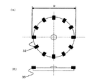
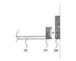
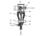
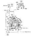
図1は、本発明に使用される表面改質装置の好適な一例を示す概略断面図である。図2(A)および(B)は、ディスク33を有する分散ローター32の外径Dを説明するための説明図であり、図3は、分散ローター32とライナー34との最小間隔を説明するための説明図であり、図4は、ディスク33の高さHを説明するための説明図である。
FIG. 1 is a schematic cross-sectional view showing a preferred example of a surface modifying apparatus used in the present invention. 2A and 2B are explanatory views for explaining the outer diameter D of the
図1に示す回分式表面改質装置は、円筒形状の本体ケーシング30、本体ケーシングの上部に開閉可能なよう設置された天板43;微粉排出ケーシングと微粉排出管とを有する微粉排出部44;冷却水或いは不凍液を通水できる冷却ジャケット31;表面改質手段としての、本体ケーシング30内にあって中心回転軸に取り付けられた、上面に角型のディスク33を複数個有し、所定方向に高速に回転する円盤状の回転体である分散ローター32;分散ローター32の周囲に一定間隔を保持して固定配置された、分散ローター32に対向する表面に多数の溝が設けられているライナー34;微粉砕物中の所定粒径以下の微粉及び超微粉を連続的に除去するための分級ローター35;本体ケーシング30内に冷風を導入するための冷風導入口46;微粉砕物(原料)を導入するために本体ケーシング30の側面に形成された原料投入口37及び原料供給口39を有する投入管;表面改質処理後のトナー粒子を本体ケーシング30外に排出するための製品排出口40及び製品抜取口42を有する製品排出管;表面改質時間を自在に調整できるように、原料投入口37と原料供給口39との間に設置された開閉可能な原料供給弁38;及び製品排出口40と製品抜取口42との間に設置された製品排出弁41を有している。 The batch type surface reforming apparatus shown in FIG. 1 includes a cylindrical main body casing 30, a top plate 43 installed so as to be openable and closable at the upper part of the main body casing; a fine powder discharge section 44 having a fine powder discharge casing and a fine powder discharge pipe; A cooling jacket 31 through which cooling water or antifreeze can be passed; a plurality of square disks 33 on the upper surface, which are attached to the central rotating shaft in the main body casing 30 as surface modification means, in a predetermined direction Dispersion rotor 32, which is a disk-like rotating body that rotates at high speed; liner 34 that is fixedly arranged around dispersion rotor 32 at a constant interval and that has a large number of grooves on the surface facing dispersion rotor 32 A classification rotor 35 for continuously removing fine powder and ultrafine powder having a predetermined particle size or less in the finely pulverized product; cold air inlet 4 for introducing cold air into the main body casing 30; A charging pipe having a raw material charging port 37 and a raw material supplying port 39 formed on the side surface of the main body casing 30 for introducing finely pulverized material (raw material); discharging toner particles after the surface modification treatment to the outside of the main body casing 30; A product discharge pipe having a product discharge port 40 and a product extraction port 42 for opening and closing; an openable and closable raw material installed between the raw material input port 37 and the raw material supply port 39 so that the surface modification time can be freely adjusted A supply valve 38; and a product discharge valve 41 installed between the product discharge port 40 and the product extraction port 42.
本発明のトナーの製造方法に使用する表面改質装置の特徴の一つは、分散ローター32の外径Dが120mm以上であり、分散ローター32の上面に設置されているディスク33とライナー34の最小間隔を1.0〜3.0mmとすることである。好ましくは、分散ローター32の外径Dは、200乃至600mmがよい。さらに、ディスク33は、上記の如く角型のディスクが好ましい。
One of the features of the surface modification apparatus used in the toner production method of the present invention is that the outer diameter D of the
分散ローター32の上面に設置されているディスク33とライナー34の最小間隔とは、図3に示す通り、分散ローター32の上面に設置されているディスク33の中心部と、ライナー34の先端部との最短距離のことである。
As shown in FIG. 3, the minimum distance between the
分散ローター32の上面に設置されているディスク33と、ライナー34の最小間隔を、1.0mm乃至3.0mmすることにより、トナー粒子の表面改質に伴う過度な粉砕を防止し、熱の影響が少なく、微粉及び超微粉の少ないシャープな粒度分布を有し、球形度の高いトナー粒子が効率良く得られる。さらに、トナー粒子の表面形状を、任意にコントロールすることができ、良好な現像性、転写性並びにクリーニング性、及び安定した帯電性を有する、長寿命のトナーを得ることができる。
By setting the minimum distance between the
表面改質処理がなされたトナー粒子の表面形状は、分散ローター32の上面に複数設置されたディスク33と分散ローター32の周囲に一定間隔を保持して固定配置されたライナーとの最小間隔に影響される。分散ローター32の上面に設置されたディスク33とライナー34の最小間隔を適切な状態に制御することで、ディスクとライナーとの間で行われるトナー粒子の表面処理具合をコントロールすることが重要である。本発明において、表面改質処理工程で使用する表面改質装置として、図1に示す回分式の表面改質装置を使用し、原料供給弁38を閉じてからから製品排出弁41を開放するまでのトナー粒子の処理時間及び分散ローター32の上面に設置されているディスク33とライナー34の最小間隔を適切な状態に制御することにより、表面改質処理時における微粉及び超微粉の増加を防止し、トナー粒子の表面形状を、任意に良好にコントロールすることができる。
The surface shape of the toner particles subjected to the surface modification treatment affects the minimum distance between the plurality of
ライナー34は、表面に多数の溝が設けられていることが好ましい。トナー粒子の表面形状をコントロールするためには、表面改質装置内でのトナー粒子の滞留時間をコントロールすることが重要である。
The
分散ローター32とライナー34の最小間隔を1.0mm未満とすると、装置自体の負荷が大きくなり、表面改質時にトナー粒子が過粉砕されやすく、熱によるトナー粒子の表面の変質や装置内のトナー粒子の融着を起こしやすくなり、トナー粒子の生産性が低下する。分散ローター32とライナー33の最小間隔を、3.0mmを超える場合は、球形度の高いトナー粒子を得るために、分散ローター32を高速運転しなければならず、表面改質時にトナー粒子が過粉砕されやすく、熱によるトナー粒子の表面の変質や装置内のトナー粒子の融着を起こしやすく、トナー粒子の生産性が低下する。
If the minimum distance between the
更に、分散ローター32の上面に設置されているディスク33の数をnとし、分散ローター32の外径をD(図2参照)とした場合、下記式(1)の関係を満足することが好ましい。
44.9≦π×D/n≦125.6(mm) (1)
Furthermore, when the number of the
44.9 ≦ π × D / n ≦ 125.6 (mm) (1)
更に、分散ローター32の上面に設置されているディスク33の高さをHとし、分散ローター32の外径をDとしたとき、下記式(2)から算出されるαの値が下記式(3)を満足することが好ましい。
Furthermore, when the height of the
![]()
![]()
図3に示すように溝を有しているライナー34は、トナー粒子の表面改質を効率的におこなう上でこのましい。ディスク33の個数は、図2(A)に示すように、分散ローター32の回転バランスを考慮して、偶数個が好ましい。分散ローター32の回転方向は、図10(A)及び(B)に示すように、通常装置上面から見て反時計方向である。
As shown in FIG. 3, the
図1及び図12に示す分級ローター35は、分散ローター32の回転方向と同方向に回転するのが、分級の効率を高め、トナー粒子の表面改質の効率を高める上で好ましい。
The classifying rotor 35 shown in FIGS. 1 and 12 is preferably rotated in the same direction as the rotation direction of the
該表面改質装置は、更に、天板43に対して垂直な軸を有する案内手段としての円筒状のガイドリング36を本体ケーシング30内に有している。該ガイドリング36は、その上端が天板から所定距離離間して設けられており、分級ローター36の少なくとも一部を覆うようにガイドリングは、支持体により本体ケーシング30に固定されている。ガイドリング36の下端は分散ローター32の角形ディスク33から所定距離離間して設けられる。該表面改質装置内において、分級ローター35と分散ローター32との間の空間が、ガイドリング36の外側の第一の空間47と、ガイドリング36の内側の第二の空間48とにガイドリング36によって二分される。第一の空間47は微粉砕物及び表面改質処理された粒子を分級ローター35へ導くための空間であり、第二の空間は微粉砕物及び表面改質処理された粒子を分散ローターへ導くための空間である。分散ローター32上に複数個設置された角型のディスク33と、ライナー34との間隙部分が表面改質ゾーン49であり、該分級ローター35及び該分級ローター35の周辺部分が分級ゾーン50である。
The surface modification apparatus further includes a cylindrical guide ring 36 as a guide means having an axis perpendicular to the
微粉排出管は、分級ローター35により除去された微粉及び超微粉を装置外に排出するための微粉排出口45を有している。
The fine powder discharge pipe has a fine
図10(A)および(B)は、該投入部の投入管と該微粉排出部の微粉排出管との角度θを説明するための図であり、図1の表面改質装置の概略的な上面投影図(水平投影面図)である。図11は該表面改質装置の該投入部の投入管と該微粉排出部の微粉排出管との位置関係を説明するための模式的斜視図である。 FIGS. 10A and 10B are views for explaining an angle θ between the charging pipe of the charging section and the fine powder discharging pipe of the fine powder discharging section, and is a schematic diagram of the surface modification apparatus of FIG. It is a top view (horizontal projection surface view). FIG. 11 is a schematic perspective view for explaining the positional relationship between the charging pipe of the charging section and the fine powder discharging pipe of the fine powder discharging section of the surface reforming apparatus.
表面改質処理装置に導入される微粉砕物は、溶融混練物を冷却した固形物を粗粉砕した粗粉砕物を例えば図8に示す微粉砕システムに導入して調製することができる。微粉砕システムにおいて、粗粉砕物を原料供給機433に導入し、原料供給機433から搬送管434を経由して風力分級機432に導入する。風力分級機432は、コレクター438内にセンターコア440及びセパレートコア441を有している。風力分級機432内において、二次エアー供給口443から導入される2次エアにより粗粉砕物は、微粉砕物と粗粒子に分級される。分級された微粉砕物は、排出管442を経由してシステム外に排出され、図12に示す原料ホッパ380に導入される。分級された粗粒子は、本体ホッパー部439を経由して微粉砕機(例えば、ジェットミル)431に導入される。微粉砕機においては、圧縮空気が導入されているノズル435に粗粒子を供給し、粗粒子を高速の圧縮空気で搬送して、粉砕室437の衝突板436に衝突させて微粉砕し、粗粒子の微粉砕物を搬送管434を経由して風力分級機432に導入して、再度分級する。
The finely pulverized product introduced into the surface modification treatment apparatus can be prepared by introducing a coarsely pulverized product obtained by roughly pulverizing a solid material obtained by cooling the melt-kneaded product into, for example, a fine pulverization system shown in FIG. In the fine pulverization system, the coarsely pulverized product is introduced into the raw
微粉砕物の重量平均径が、3.5〜9.0μmであり、且つ粒径が3.17μm以下の粒子の割合が30〜70個数%であることが、後工程で効率良く分級工程及び粒子の表面処理工程を同時に表面改質装置内で効率良くおこなう上で好ましい。 The weight average diameter of the finely pulverized product is 3.5 to 9.0 μm, and the ratio of the particles having a particle size of 3.17 μm or less is 30 to 70% by number. It is preferable to perform the particle surface treatment step at the same time in the surface modification apparatus efficiently.
図12に示す如く、原料ホッパー380に導入される微粉砕物は、定量供給機315を経由して、投入管の原料投入口37から原料供給弁38を通って原料供給口39より装置内に供給される。表面改質装置には、冷風発生手段319で発生させた冷風を冷風導入口46から本体ケーシング内に供給し、さらに、冷水発生手段320からの冷水を冷水ジャッケト31に供給し、本体ケーシング内の温度を所定温度に調整する。供給された微粉砕物は、ブロアー364による吸引風量、分散ローター32の回転及び分級ローター35の回転により形成される旋回流により、円筒状のガイドリング36の外側の第一の空間47を旋回しながら分級ローター35近傍の分級ゾーン50に到達して分級処理が行われる。本体ケーシング30内に形成される旋回流の向きは、分散ローター32及び分級ローター35の回転方向と同じであるので、装置上面よりみて反時計方向となる。
As shown in FIG. 12, the finely pulverized product introduced into the
表面改質装置において、天板43と分級ローター35との接面部は密着させず、適当な隙間を設けることが好ましい。分級ローター35と天板43との対向面部の間隔は、好ましくは1.0mm以下、より好ましくは0.1乃至0.9mmがよい。該間隔からエアーが吹き出す構成とすると更に好ましい。該間隔が1.0mmを超えると、トナー粒子が該間隔から分級ローターを通過せずに、ケーシング30へのショートパスが発生する恐れがある。該間隔から吹き出すエアー流量は、0.5m3/min以上が好ましく、1.0m3/min以上がより好ましい。エアー圧は、0.05MPa以上が好ましく、0.1MPa以上がより好ましい。
In the surface modification apparatus, it is preferable that the contact surface between the
更に、本発明のトナーの製造方法においては、表面改質装置におけるトナー粒子の表面改質時間が5秒乃至180秒であることが好ましく、15秒乃至120秒であることがより好ましい。表面改質時間が5秒未満の場合、球形度の高いトナー粒子が得られにくく、品質の良いトナー粒子が得られにくい。一方、表面改質時間が180秒を超える場合、表面改質時間が長すぎるため、表面改質時に発生する熱によるトナー粒子の表面が変質されやすく、装置内のトナー粒子の融着が発生しやすく、トナー粒子の生産性が低下する傾向にある。 Furthermore, in the toner production method of the present invention, the surface modification time of the toner particles in the surface modification device is preferably 5 seconds to 180 seconds, and more preferably 15 seconds to 120 seconds. When the surface modification time is less than 5 seconds, it is difficult to obtain toner particles with high sphericity, and it is difficult to obtain good quality toner particles. On the other hand, when the surface modification time exceeds 180 seconds, the surface modification time is too long, and the surface of the toner particles is easily deteriorated by the heat generated during the surface modification, and the toner particles in the apparatus are fused. This tends to reduce the toner particle productivity.
更に、本発明のトナーの製造方法においては、該分散ローターの回転時の先端周速は30〜175m/secとすることが好ましく、40〜160m/secとすることがより好ましい。分散ローター32の周速が30m/sec未満であると、所定の円形度のトナー粒子を得るためには処理能力を落とさなければならず、トナー粒子の生産性が低下する傾向にある。一方、分散ローター32の回転周速が175m/secを超えると、装置自体の負荷が大きくなり、表面改質時にトナー粒子が過粉砕されやうく、熱によるトナー粒子の表面が変質されやすく、装置内のトナー粒子の融着を起こしやすい。
Furthermore, in the toner production method of the present invention, the tip peripheral speed during rotation of the dispersion rotor is preferably 30 to 175 m / sec, and more preferably 40 to 160 m / sec. If the peripheral speed of the
更に、本発明のトナーの製造方法においては、該表面改質装置内の分散ローター32上面に設置されているディスク33の上面と、円筒型のガイドリング36の下端の最小間隔を2.0〜50.0mmとすることが好ましく、5.0〜45.0mmとすることがより好ましい。該表面改質装置内のディスク33の上面と、円筒型のガイドリング36の下端の最小間隔を2.0mm未満であると、装置自体の負荷が大きくなりやすく、ガイドリング36の内側の第一の空間でのトナー粒子の滞留時間が長くなりやすく、表面改質時に過粉砕され熱によるトナー粒子の表面が変質されやすく、装置内のトナー粒子の融着が起こしやすい。また、ディスク33の上面と、円筒型のガイドリング36の下端の最小間隔を50.0mmが超えると、トナー粒子が十分に表面改質されない状態でガイドリング36の外側の第二の空間へ流出するというショートパスを起こしやすい。
Furthermore, in the toner manufacturing method of the present invention, the minimum distance between the upper surface of the
更に、本発明のトナーの製造方法においては、該表面改質装置内のガイドリング36と、装置内壁との間の最小間隔が20.0mm乃至60.0mmとすることが好ましく、更には、25.0mm乃至55.0mmとすることが好ましい。該表面改質装置内のガイドリング36と、装置内壁との間の最小間隔が20.0mm未満であると、ガイドリング36の内側の第二の空間での滞留時間が短くなり、トナー粒子が十分に表面改質されない状態でガイドリング36の外側の第一の空間へ流出する可能性があり、トナー粒子の生産性が低下しやすい。また、表面改質装置内のガイドリング36と、装置内壁との間の最小間隔が60.0mmを超える場合、分散ローター32近傍でのトナー粒子の滞留時間が長くなり、表面改質時にトナー粒子が粉砕されやすく、熱によりトナー粒子の表面が変質されやすく、装置内でトナー粒子の融着が起こりやすい。
Furthermore, in the toner production method of the present invention, the minimum distance between the guide ring 36 in the surface modification device and the inner wall of the device is preferably 20.0 mm to 60.0 mm, and further 25 It is preferable that the thickness is 0.0 mm to 55.0 mm. When the minimum distance between the guide ring 36 in the surface modification device and the inner wall of the device is less than 20.0 mm, the residence time in the second space inside the guide ring 36 is shortened, and the toner particles are reduced. If the surface is not sufficiently modified, it may flow out to the first space outside the guide ring 36, and the toner particle productivity tends to be lowered. In addition, when the minimum distance between the guide ring 36 in the surface modifying device and the inner wall of the device exceeds 60.0 mm, the residence time of the toner particles in the vicinity of the
更に、本発明のトナーの製造方法においては、表面改質装置内に導入する冷風温度T1を5℃以下とすることが好ましい。表面改質装置内に導入する冷風温度T1を5℃以下(より好ましくは0℃以下、更に好ましくは−5℃乃至−40℃)とすることにより、表面改質時に発生する熱によるトナー粒子の表面の変質が抑制され、装置内のトナー粒子の融着を良好に防止することができる。表面改質装置内に導入する冷風温度T1が5℃を超える場合は、表面改質時に発生する熱によるトナー粒子の表面が変質されやすく、装置内のトナー粒子の融着を起こりやすい。 Furthermore, in the toner production method of the present invention, it is preferable that the cold air temperature T1 introduced into the surface reforming apparatus is 5 ° C. or less. By setting the cold air temperature T1 introduced into the surface reforming apparatus to 5 ° C. or lower (more preferably 0 ° C. or lower, more preferably −5 ° C. to −40 ° C.), Surface alteration is suppressed, and it is possible to satisfactorily prevent fusion of toner particles in the apparatus. When the cold air temperature T1 introduced into the surface reforming apparatus exceeds 5 ° C., the surface of the toner particles is easily altered by the heat generated during the surface modification, and the toner particles in the apparatus are likely to be fused.
表面改質装置内に導入する冷風の発生装置で使用する冷媒としては、地球全体の環境問題という点から代替フロンが好ましい。代替フロンとしては、R134a、R404A、R407c、R410A、R507A、R717が挙げられる。この中で、省エネルギー性や安全性という点から、特にR404Aが好ましい。 As the refrigerant used in the cold air generating apparatus introduced into the surface reforming apparatus, an alternative chlorofluorocarbon is preferable from the viewpoint of the global environmental problems. Alternative CFCs include R134a, R404A, R407c, R410A, R507A, and R717. Among these, R404A is particularly preferable from the viewpoints of energy saving and safety.
表面改質装置内に導入する冷風は、装置内の結露防止という面から、除湿したものであることがトナー粒子の生産性上好ましい。冷風の除湿装置としては公知のものが使用できる。給気露点温度としては、−15℃以下が好ましく、更には−20℃以下が好ましい。 The cold air introduced into the surface reforming apparatus is preferably dehumidified from the viewpoint of preventing condensation in the apparatus from the viewpoint of toner particle productivity. As the cold air dehumidifying device, a known device can be used. The supply air dew point temperature is preferably −15 ° C. or lower, and more preferably −20 ° C. or lower.
更に、表面改質装置は、冷却用のジャケットを更に具備していることが好ましい。該ジャケット内に冷媒(好ましくは冷却水、更に好ましくはエチレングリコールの如き不凍液)を通しながらトナー粒子を表面改質処理することが好ましい。該ジャケットにより装置内を冷却することにより、表面改質時における熱によるトナー粒子の表面の変質が抑制され、装置内のトナー粒子の融着を良好に防止することができる。 Furthermore, it is preferable that the surface modification device further includes a cooling jacket. The toner particles are preferably subjected to surface modification treatment while passing a coolant (preferably cooling water, more preferably an antifreeze such as ethylene glycol) through the jacket. By cooling the inside of the apparatus with the jacket, it is possible to suppress deterioration of the surface of the toner particles due to heat at the time of surface modification and to prevent the toner particles in the apparatus from being fused well.
表面改質装置のジャケット内に通す冷媒の温度は5℃以下とすることが好ましい。該トナー粒子回分式表面改質装置内のジャケット内に通す冷媒の温度を5℃以下(より好ましくは0℃以下、更に好ましくは−5℃以下)とすることにより、表面改質時に発生する熱によるトナー粒子の表面の変質が抑制され、装置内のトナー粒子の融着を良好に防止することができる。 The temperature of the refrigerant passed through the jacket of the surface reformer is preferably 5 ° C. or lower. Heat generated at the time of surface modification is controlled by setting the temperature of the refrigerant passed through the jacket in the toner particle batch type surface modification device to 5 ° C. or less (more preferably 0 ° C. or less, more preferably −5 ° C. or less). As a result, the surface quality of the toner particles can be prevented from being deteriorated, and the toner particles in the apparatus can be prevented from being fused well.
また、本発明のトナーの製造方法においては、表面改質装置内の分級ローター35後方にある、微粉排出口45内の温度T2を60℃以下とすることが好ましい。該温度T2を60℃以下(更に好ましくは50℃以下)とすることにより、表面改質時に発生する熱によるトナー粒子の表面の変質が抑制され、装置内のトナー粒子の融着を防止することができる。
In the toner production method of the present invention, it is preferable that the temperature T2 in the
更に、本発明のトナーの製造方法においては、微粉排出口内の温度T2と、表面改質装置に導入される冷風温度T1との温度差ΔT(T2−T1)を100℃以下とすることが好ましい。該温度差ΔT(T2−T1)を100℃以下(更に好ましくは80℃以下)とすることにより、表面改質時に発生する熱によるトナー粒子の表面の変質が良好に抑制され、装置内のトナー粒子の融着を防止することができる。 Furthermore, in the toner manufacturing method of the present invention, it is preferable that the temperature difference ΔT (T2−T1) between the temperature T2 in the fine powder discharge port and the cold air temperature T1 introduced into the surface reformer is 100 ° C. or less. . By setting the temperature difference ΔT (T2−T1) to 100 ° C. or less (more preferably 80 ° C. or less), the surface quality of the toner particles due to the heat generated during the surface modification is well suppressed, and the toner in the apparatus Particle fusion can be prevented.
分級ローター35によって除去されるべき微粉及び超微粉は、ブロワー364の吸引力より分級ローター35のスリットより吸引され微粉排出管の微粉排出口45及びサイクロン入口359を経由してサイクロン369及びバグ362に捕集される。微粉及び超微粉を除去された微粉砕物は第二の空間48を経由して分散ローター32近傍の表面改質ゾーン49に至り、分散ローター32に具備される角型ディスク33(ハンマー)と本体ケーシング30に具備されたライナー34によって粒子の表面改質処理が行われる。表面改質が行われた粒子はガイドリング36に沿って旋回しながら再び分級ローター35近傍に到達し、分級ローター35の分級により表面改質された粒子からの微粉及び超微粉の除去がおこなわれる。所定の時間処理を行った後、排出弁41を開き、表面改質装置から所定粒径以下の微粉及び超微粉が除かれた表面改質されたトナー粒子を取り出す。
Fine powder and super fine powder to be removed by the classifying rotor 35 are sucked from the slit of the classifying rotor 35 by the suction force of the
所定の重量平均径に調整され、所定の粒度分布に調整され、さらに所定の円形度に表面改質されたトナー粒子は、トナー粒子の輸送手段321により外添剤の外添工程に移送される。 The toner particles adjusted to a predetermined weight average diameter, adjusted to a predetermined particle size distribution, and further surface-modified to a predetermined circularity are transferred to the external additive adding step by the toner particle transport means 321. .
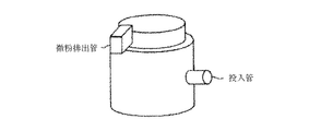
該投入部は、該本体ケーシングの側面に形成されていることが好ましく、該微粉排出部は該本体ケーシングの上面に形成されていることが好ましい。 The charging portion is preferably formed on the side surface of the main body casing, and the fine powder discharge portion is preferably formed on the upper surface of the main body casing.
図10(A)及び図10(B)に示すように、表面改質装置の上面投影図において該投入部の投入管の中心位置S1から第一の空間への該微粉砕物の投入方向に伸びる直線をL1とし、該微粉排出部の微粉排出管の中心位置O1から微粉及び超微粉の排出方向に伸びる直線をL2とした時、直線L1と直線L2のなす角θが、該分級ローターの回転方向を基準にして210〜330度であることがトナー粒子の収率を高める上で好ましい。 As shown in FIGS. 10 (A) and 10 (B), in the top projection view of the surface modification apparatus, the finely pulverized product is introduced from the center position S1 of the input pipe of the input unit into the first space in the input direction. When the straight line extending is L1, and the straight line extending from the center position O1 of the fine powder discharge pipe of the fine powder discharge portion in the fine powder and super fine powder discharge direction is L2, the angle θ formed by the straight line L1 and the straight line L2 is the angle of the classification rotor. From the viewpoint of increasing the toner particle yield, it is preferably 210 to 330 degrees with respect to the rotation direction.
微粉砕物(原料)の投入管の位置と微粉排出管の位置との関係がトナー粒子の収率の向上及得られるトナーのかぶり現象の改善に影響を及ぼすことを見出した。表面改質装置の上面から見た図10(A)及び図10(B)に示す上面投影図において、投入管の原料投入口37の中心位置と微分排出管の微粉排出口45の中心位置との関係が、投入部(原料投入口39)の中心位置S1から投入方向に伸びる直線をL1とし、微粉排出部の中心位置O1から排出方向に伸びる直線をL2とした時、交点M1における直線L1と直線L2のなす角度θが分級ローター35の回転方向を基準として210〜330度であることが好ましい。図10(A)及び図10(B)において、M1は、微粉排出ケーシング44の中心位置を示す。図10(B)に示すように、微粉砕物の投入管は、本体ケーシング30に対して接線方向に配置し、円筒状のガイドリング36の外壁の接線方向に微粉砕物を導入することが、微粉砕物の分級効率を高める上で好ましい。
It has been found that the relationship between the position of the finely pulverized product (raw material) input pipe and the position of the fine powder discharge pipe affects the improvement in the yield of toner particles and the improvement of the fogging phenomenon of the toner obtained. 10A and 10B viewed from the upper surface of the surface reforming apparatus, the center position of the raw
図10(A)及び図2(B)に示すように、投入部の中心位置S1とは、投入管の径(又は幅)の中点を示し、微粉排出部の中心位置O1とは、微粉排出管の径(又は幅)の中点を示す。角度θは、中点S1を通過して原料投入方向と平行に伸びる直線L1と中点O1を通過して微粉排出方向に伸びる直線L2との交点をM2とした時に、直線S1―M2と直線O1−M2とのなす角度θをいう。角度θは分散ローター32及び分級ローター35の回転方向を正として定義する。前述したように、図10(A)及び図10(B)の場合は、M1を中心として分散ローター32及び分級ローター35が反時計方向に回転する場合である。角度θが180度の場合は投入方向と排出方向が同一かつ平行であり、角度θが0度の場合は投入方向と排出方向が逆でありかつ平行である。
As shown in FIGS. 10 (A) and 2 (B), the center position S1 of the charging part indicates the midpoint of the diameter (or width) of the charging pipe, and the center position O1 of the fine powder discharging part is fine powder. Indicates the midpoint of the diameter (or width) of the discharge pipe. The angle θ is a straight line with a straight line S1-M2 when the intersection of a straight line L1 passing through the middle point S1 and extending in parallel with the raw material charging direction and a straight line L2 passing through the middle point O1 and extending in the fine powder discharge direction is M2. The angle θ formed with O1-M2. The angle θ is defined with the rotation direction of the
本発明の表面改質装置は、鉛直方向下側より分散ローター32、微粉砕物(原料)の投入部39、分級ローター35及び微粉排出部を有している。従って、通常、分級ローター35の駆動部分(モーター等)は分級ローター35の更に上方に設けられ、分散ローター32の駆動部分は分散ローター32の更に下方に設ける。本発明で用いる表面改質装置は、例えば特開2001―259451号公報に記載されている分級ローター35のみを有するTSP分級機(ホソカワミクロン社製)の様に、微粉砕物(原料)を分級ローター35の鉛直上方向より供給することは困難である。
The surface reforming apparatus of the present invention includes a
本発明に用いられる表面改質装置の場合は、原料供給方向及び微粉排出方向は、分級ローター35及び分散ローター32の回転面と平行又は実質的に平行になる様設けることが好ましい。微粉排出方向(吸引方向)が分級ローター35の回転面と平行又は実質的に平行の場合は、原料供給方向と微粉排出方向の角度θが所定の粒径の粒子を高収率で得るために重要である。原料供給方向と微粉排出方向の角度θを調整することにより、原料の微粉砕物中の凝集粉体を良好に微分散させた後に分級ローター35近傍の分級ゾーン50に微粉砕物を導入することができる。
In the case of the surface reforming apparatus used in the present invention, it is preferable to provide the raw material supply direction and the fine powder discharge direction so as to be parallel or substantially parallel to the rotation surfaces of the classification rotor 35 and the
微粉砕物の投入部と微粉排出部との位置関係において、角θが0乃至180度の場合は、分散ローター32で形成される旋回流により微粉砕物中の凝集粉体を充分に微分散する前に、ブロアー364の吸引力が分級ローター35を介して作用する傾向にあり、第1の空間47に投入された微粉砕物の分散が不十分となりやすく、微粉及超微粉の分級効率が低下し、分級時間が長くなり分級収率が低下する傾向にある。角度θが210〜330度の場合は、分散ローター32で形成される旋回流により微粉砕物中の凝集粉体を充分に微分散でき、分級ローターで形成される遠心力が効果的に作用する為良好な分級収率を得ることができる。上記効果をより発揮するには、角θが225〜315度であることが好ましく、さらに250〜290度であることがより好ましい。
When the angle θ is 0 to 180 degrees in the positional relationship between the finely pulverized product input portion and the fine powder discharge portion, the aggregated powder in the finely pulverized material is sufficiently finely dispersed by the swirl flow formed by the
本発明において、分級ローター35の最も径の大きい箇所の先端周速は30〜120m/secであることが好ましい。分級ローターの先端周速は50〜115m/secであることがより好ましく、70〜110m/secであることが更に好ましい。30m/secより遅い場合は、分級収率が低下しやすく、トナー粒子中に超微粉が増加する傾向にあり好ましくない。120m/secより速い場合は、装置の振動の増加の問題が生じやすい。 In the present invention, it is preferable that the tip peripheral speed of the classification rotor 35 having the largest diameter is 30 to 120 m / sec. The tip circumferential speed of the classification rotor is more preferably 50 to 115 m / sec, and further preferably 70 to 110 m / sec. If it is slower than 30 m / sec, the classification yield tends to decrease, and the amount of ultrafine powder tends to increase in the toner particles. If it is faster than 120 m / sec, the problem of increased vibration of the device is likely to occur.
本発明における「表面改質」とは、粒子表面の凸凹を円滑にすることであり、粒子の外観形状を球形に近づけることをいう。このような本発明の表面改質粒子の表面改質の度合いを示すものとして、本発明においては平均円形度をその指標とする。 “Surface modification” in the present invention means smoothing the unevenness of the particle surface, and means that the appearance shape of the particle is close to a sphere. As an indicator of the degree of surface modification of the surface modified particles of the present invention, the average circularity is used as an index in the present invention.
本発明における平均円形度は、フロー式粒子像測定装置「FPIA−2100型」(シスメックス社製)を用いて測定を行い、下式を用いて算出する。 The average circularity in the present invention is measured using a flow type particle image measuring device “FPIA-2100 type” (manufactured by Sysmex Corporation), and is calculated using the following equation.

ここで、「粒子投影面積」とは二値化された粒子像の面積であり、「粒子投影像の周囲長」とは該粒子像のエッジ点を結んで得られる輪郭線の長さと定義する。測定は、512×512の画像処理解像度(0.3μm×0.3μmの画素)で画像処理した時の粒子像の周囲長を用いる。 Here, “particle projection area” is the area of the binarized particle image, and “perimeter of the particle projection image” is defined as the length of the contour line obtained by connecting the edge points of the particle image. . The measurement uses the perimeter of the particle image when image processing is performed at an image processing resolution of 512 × 512 (pixels of 0.3 μm × 0.3 μm).
本発明における円形度は粒子の凹凸の度合いを示す指標であり、粒子が完全な球形の場合に1.000を示し、表面形状が複雑になる程、円形度は小さな値となる。 In the present invention, the circularity is an index indicating the degree of unevenness of the particles, and is 1.000 when the particles are perfectly spherical. The more complicated the surface shape, the smaller the circularity.
また、円形度頻度分布の平均値を意味する平均円形度Cは、粒度分布の分割点iでの円形度(中心値)をci、測定粒子数をmとすると、次式から算出される。 The average circularity C, which means the average value of the circularity frequency distribution, is calculated from the following equation, where ci is the circularity (center value) at the dividing point i of the particle size distribution and m is the number of measured particles.
円形度標準偏差SDは、平均円形度C、各粒子における円形度ci、測定粒子数をmとすると次式から算出される。 The circularity standard deviation SD is calculated from the following equation where the average circularity C, the circularity ci of each particle, and the number of measured particles are m.
本発明で用いている測定装置である「FPIA−2100」は、各粒子の円形度を算出後、平均円形度及び円形度標準偏差の算出に当たって、得られた円形度によって、粒子を円形度0.4〜1.0を0.01ごとに等分割したクラスに分け、その分割点の中心値と測定粒子数を用いて平均円形度及び円形度標準偏差の算出を行う。 “FPIA-2100”, which is a measuring device used in the present invention, calculates the circularity of each particle, and then calculates the average circularity and the circularity standard deviation. .4 to 1.0 are divided into classes equally divided every 0.01, and the average circularity and the circularity standard deviation are calculated using the center value of the division points and the number of measured particles.
具体的な測定方法としては、容器中に予め不純固形物などを除去したイオン交換水20mlを用意し、その中に分散剤として界面活性剤(好ましくはアルキルベンゼンスルホン酸塩)を加えた後、更に測定試料を試料濃度が2000〜5000個/μlとなるように均一に分散させる。分散させる手段としては、超音波分散機「ULTRASONIC CLEANER VS−150型」(アズワン株式会社製)を用い、下記の条件で1分間分散処理を行い、測定用の分散液とする。その際、該分散液の温度が40℃以上とならない様に適宜冷却する。また、円形度のバラツキを抑えるため、フロー式粒子像分析装置FPIA−2100の機内温度が26〜27℃になるよう装置の設置環境を23℃±0.5℃にコントロールし、一定時間おきに、好ましくは2時間おきに2μmラテックス粒子を用いて自動焦点調整を行う。 As a specific measuring method, 20 ml of ion-exchanged water from which impure solids have been removed in advance is prepared in a container, and after adding a surfactant (preferably alkylbenzene sulfonate) as a dispersant, The measurement sample is uniformly dispersed so that the sample concentration is 2000 to 5000 / μl. As a means to disperse, an ultrasonic disperser “ULTRASONIC CLEANER VS-150 type” (manufactured by ASONE Co., Ltd.) is used, and a dispersion treatment is performed for 1 minute under the following conditions to obtain a dispersion for measurement. In that case, it cools suitably so that the temperature of this dispersion may not be 40 degreeC or more. In order to suppress variation in circularity, the installation environment of the apparatus is controlled at 23 ° C. ± 0.5 ° C. so that the temperature inside the flow type particle image analyzer FPIA-2100 is 26 to 27 ° C. Preferably, autofocus is performed using 2 μm latex particles every 2 hours.
[超音波発振器による分散条件]
装置:ULTRASONIC CLEANER VS−150型(アズワン株式会社製)
定格:出力 50kHz 150W
粒子の円形度測定には、前記フロー式粒子像測定装置を用い、測定時のトナー粒子濃度が3000〜1万個/μlとなる様に該分散液濃度を再調整し、粒子を1000個以上計測する。計測後、このデータを用いて、円相当径2μm未満のデータをカットして、粒子の平均円形度を求める。
[Dispersion condition by ultrasonic oscillator]
Apparatus: ULTRASONIC CLEANER VS-150 (manufactured by ASONE CORPORATION)
Rating: Output 50kHz 150W
For the measurement of the circularity of the particles, the flow type particle image measuring device is used, the concentration of the dispersion is readjusted so that the toner particle concentration at the time of measurement is 3000 to 10,000 / μl, and 1000 or more particles are obtained. measure. After the measurement, using this data, data having an equivalent circle diameter of less than 2 μm is cut to determine the average circularity of the particles.
更に本発明で用いている測定装置「FPIA−2100」は、トナー又はトナー粒子の形状を算出するために用いられていた「FPIA−1000」と比較して、処理粒子画像の倍率の向上、更に取り込んだ画像の処理解像度を向上(256×256→512×512)させることにより粒子の形状測定の精度が上がっており、それにより微粒子のより確実な捕捉を達成している装置である。従って、本発明のように、より正確に粒子の形状を測定する必要がある場合には、FPIA2100の方が有用である。 Furthermore, the measuring device “FPIA-2100” used in the present invention improves the magnification of the processed particle image as compared with “FPIA-1000” used to calculate the shape of the toner or toner particles. By improving the processing resolution of the captured image (256 × 256 → 512 × 512), the accuracy of particle shape measurement is improved, thereby achieving more reliable capture of fine particles. Therefore, the FPIA 2100 is more useful when it is necessary to measure the particle shape more accurately as in the present invention.
本発明における測定の概略は、以下の通りである。 The outline of the measurement in the present invention is as follows.
試料分散液は、フラットで扁平なフローセル(厚み約200μm)の流路(流れ方向に沿って広がっている)を通過させる。フローセルの厚みに対して交差して通過する光路を形成するように、ストロボとCCDカメラが、フローセルに対して、相互に反対側に位置するように装着される。試料分散液が流れている間に、ストロボ光がフローセルを流れている粒子の画像を得るために1/30秒間隔で照射され、その結果、それぞれの粒子は、フローセルに平行な一定範囲を有する2次元画像として撮影される。それぞれの粒子の2次元画像の面積から、同一の面積を有する円の直径を円相当径として算出する。それぞれの粒子の2次元画像の投影面積及び投影像の周囲長から上記の円形度算出式を用いて各粒子の円形度を算出する。 The sample dispersion is passed through a flow path (expanded along the flow direction) of a flat and flat flow cell (thickness: about 200 μm). The strobe and the CCD camera are mounted on the flow cell so as to be opposite to each other so as to form an optical path that passes through the thickness of the flow cell. While the sample dispersion is flowing, strobe light is irradiated at 1/30 second intervals to obtain an image of the particles flowing through the flow cell, so that each particle has a certain range parallel to the flow cell. Photographed as a two-dimensional image. From the area of the two-dimensional image of each particle, the diameter of a circle having the same area is calculated as the equivalent circle diameter. The circularity of each particle is calculated from the projected area of the two-dimensional image of each particle and the perimeter of the projected image using the above circularity calculation formula.
図8に示すように、微粉砕物は、通常知られている衝突式気流粉砕機又は機械式粉砕機で溶融混練物の冷却物の粗粉砕物を分級し微粉砕する方法が挙げられる。機械式粉砕機としては、ターボ工業(株)製ターボミル、川崎重工業(株)製クリプトロン、ホソカワミクロン(株)製イノマイザー、日清エンジニアリング(株)製スーパーローターが挙げられる。 As shown in FIG. 8, the finely pulverized product may be a method of classifying and finely pulverizing the coarsely pulverized product of the melt-kneaded product with a generally known collision type airflow pulverizer or mechanical pulverizer. Examples of the mechanical pulverizer include a turbo mill manufactured by Turbo Industry Co., Ltd., a kryptron manufactured by Kawasaki Heavy Industries, Ltd., an inomizer manufactured by Hosokawa Micron Co., Ltd., and a super rotor manufactured by Nisshin Engineering Co., Ltd.
さらに、本発明で好適に用いられる微粉砕物を得る方法としては、I−DS型粉砕機(日本ニューマチック社製)、特開平2003−262981号公報の図1に記載されているジェットエアーを利用した衝突式気流粉砕機と、特開平2003−262981号公報の図7に記載されている分級機を使用して微粉砕物を得る方法が挙げられる。 Furthermore, as a method for obtaining a finely pulverized product suitably used in the present invention, an I-DS type pulverizer (manufactured by Nippon Pneumatic Co., Ltd.), jet air described in FIG. 1 of JP-A No. 2003-262981 is used. Examples include a method of obtaining a finely pulverized product by using a collision type airflow pulverizer and a classifier described in FIG. 7 of JP-A-2003-262981.
本発明のトナー製造方法によれば、表面改質工程によって得られた表面改質粒子の平均円形度を、該表面改質工程に導入される微粉砕物の平均円形度よりも0.01〜0.40大きくすることができる。該表面改質装置の表面改質時間を任意にコントロールすることにより、トナー粒子の表面形状を任意にコントロールすることができるためである。本装置を用いることにより、平均円形度0.935〜0.980のトナー粒子(表面改質粒子)を得ることができる。転写効率の向上及び画像の中抜けの発生防止の観点からは平均円形度を0.940乃至0.980にすることが好ましい。 According to the toner production method of the present invention, the average circularity of the surface-modified particles obtained in the surface modification step is 0.01 to more than the average circularity of the finely pulverized product introduced into the surface modification step. It can be increased by 0.40. This is because the surface shape of the toner particles can be arbitrarily controlled by arbitrarily controlling the surface modification time of the surface modifying apparatus. By using this apparatus, toner particles (surface modified particles) having an average circularity of 0.935 to 0.980 can be obtained. The average circularity is preferably 0.940 to 0.980 from the viewpoint of improving transfer efficiency and preventing the occurrence of image voids.
トナーの粒度分布は種々の方法によって測定できるが、本発明においては、次の測定装置を用いて行う。 The particle size distribution of the toner can be measured by various methods. In the present invention, the following measurement apparatus is used.
測定装置としては、コールターカウンターTA−II型又はコールターマルチサイザーII(コールター社製)を用いる。アパチャーとして100μmアパチャーを用い、トナーの体積及び個数を測定して体積分布と個数分布とを算出する。それから、本発明に係る体積分布から求める重量基準の重量平均粒径を求める。 As a measuring device, Coulter Counter TA-II type or Coulter Multisizer II (manufactured by Coulter Co.) is used. Using a 100 μm aperture as the aperture, the volume and number of toners are measured, and the volume distribution and number distribution are calculated. Then, a weight-based weight average particle diameter obtained from the volume distribution according to the present invention is obtained.
本発明の製造方法により製造されるトナーは、少なくとも結着樹脂及び着色剤を含有するトナー粒子と、このトナー粒子に必要に応じて添加混合された外添剤とを有する。 The toner produced by the production method of the present invention has toner particles containing at least a binder resin and a colorant, and an external additive added to and mixed with the toner particles as necessary.
トナー粒子の原材料について説明する。トナー粒子は、少なくとも結着樹脂及び着色剤を含有し、必要に応じて、更にワックスや荷電制御剤の如き成分を含有する。 The raw material for the toner particles will be described. The toner particles contain at least a binder resin and a colorant, and further contain components such as a wax and a charge control agent as necessary.
本発明に用いられる結着樹脂としては、従来トナーの結着樹脂として知られている樹脂を使用することができ、例えば、ビニル系樹脂、フェノール樹脂、天然樹脂変性フェノール樹脂、天然樹脂変性マレイン酸樹脂、アクリル樹脂、メタクリル樹脂、ポリ酢酸ビニル、シリコーン樹脂、ポリエステル樹脂、ポリウレタン、ポリアミド樹脂、フラン樹脂、エポキシ樹脂、キシレン樹脂、ポリビニルブチラール、テルペン樹脂、クマロインデン樹脂、石油系樹脂が挙げられる。中でもビニル系樹脂とポリエステル樹脂が帯電性や定着性の点で好ましい。 As the binder resin used in the present invention, a resin conventionally known as a binder resin for toners can be used. For example, vinyl resins, phenol resins, natural resin-modified phenol resins, natural resin-modified maleic acid Examples include resins, acrylic resins, methacrylic resins, polyvinyl acetate, silicone resins, polyester resins, polyurethanes, polyamide resins, furan resins, epoxy resins, xylene resins, polyvinyl butyral, terpene resins, coumaroindene resins, and petroleum resins. Of these, vinyl resins and polyester resins are preferred in terms of chargeability and fixability.
ビニル系樹脂としては、スチレン;o−メチルスチレン、m−メチルスチレン、p−メチレンスチレン、p−メトキシスチレン、p−フェニルスチレン、p−クロルスチレン、3,4−ジクロルスチレン、p−エチルスチレン、2,4−ジメチルスチレン、p−n−ブチルスチレン、p−tert−ブチルスチレン、p−n−ヘキシルスチレン、p−n−オクチルスチレン、p−n−ノニルスチレン、p−n−デシルスチレン、p−n−ドデシルスチレンの如きスチレン誘導体;エチレン、プロピレン、ブチレン、イソブチレンの如きエチレン不飽和モノオレフィン類;ブタジエンの如き不飽和ポリエン類;塩化ビニル、塩化ビニリデン、臭化ビニル、弗化ビニルの如きハロゲン化ビニル類;酢酸ビニル、プロピオン酸ビニル、ベンゾエ酸ビニルの如きビニルエステル類;メタクリル酸メチル、メタクリル酸エチル、メタクリル酸プロピル、メタクリル酸n−ブチル、メタクリル酸イソブチル、メタクリル酸n−オクチル、メタクリル酸ドデシル、メタクリル酸2−エチルヘキシル、メタクリル酸ステアリル、メタクリル酸フェニル、メタクリル酸ジメチルアミノエチル、メタクリル酸ジエチルアミノエチルの如きα−メチレン脂肪族モノカルボン酸エステル類;アクリル酸メチル、アクリル酸エチル、アクリル酸n−ブチル、アクリル酸イソブチル、アクリル酸プロピル、アクリル酸n−オクチル、アクリル酸ドデシル、アクリル酸2−エチルヘキシル、アクリル酸ステアリル、アクリル酸2−クロルエチル、アクリル酸フェニルの如きアクリル酸エステル類;ビニルメチルエーテル、ビニルエチルエーテル、ビニルイソブチルエーテルの如きビニルエーテル類;ビニルメチルケトン、ビニルヘキシルケトン、メチルイソプロペニルケトンの如きビニルケトン類;N−ビニルピロール、N−ビニルカルバゾール、N−ビニルインドール、N−ビニルピロリドンの如きN−ビニル化合物;ビニルナフタリン類;アクリロニトリル、メタクリロニトリル、アクリルアミドの如きアクリル酸又はメタクリル酸誘導体;α,β−不飽和酸のエステル、二塩基酸のジエステル類;アクリル酸、メタクリル酸、α−エチルアクリル酸、クロトン酸、ケイヒ酸、ビニル酢酸、イソクロトン酸、アンゲリカ酸等のアクリル酸及びそのα−又はβ−アルキル誘導体;フマル酸、マレイン酸、シトラコン酸、アルケニルコハク酸、イタコン酸、メサコン酸、ジメチルマレイン酸、ジメチルフマル酸等の不飽和ジカルボン酸及びそのモノエステル誘導体又は無水物等のビニル系モノマーを用いた重合体が挙げられる。 Examples of vinyl resins include styrene; o-methylstyrene, m-methylstyrene, p-methylenestyrene, p-methoxystyrene, p-phenylstyrene, p-chlorostyrene, 3,4-dichlorostyrene, p-ethylstyrene. 2,4-dimethylstyrene, pn-butylstyrene, p-tert-butylstyrene, pn-hexylstyrene, pn-octylstyrene, pn-nonylstyrene, pn-decylstyrene, Styrene derivatives such as pn-dodecylstyrene; ethylene unsaturated monoolefins such as ethylene, propylene, butylene and isobutylene; unsaturated polyenes such as butadiene; vinyl chloride, vinylidene chloride, vinyl bromide, vinyl fluoride, etc. Vinyl halides; vinyl acetate, vinyl propionate, vinyl benzoate Vinyl esters such as methyl; methyl methacrylate, ethyl methacrylate, propyl methacrylate, n-butyl methacrylate, isobutyl methacrylate, n-octyl methacrylate, dodecyl methacrylate, 2-ethylhexyl methacrylate, stearyl methacrylate, methacrylic acid Α-methylene aliphatic monocarboxylic acid esters such as phenyl acid, dimethylaminoethyl methacrylate, diethylaminoethyl methacrylate; methyl acrylate, ethyl acrylate, n-butyl acrylate, isobutyl acrylate, propyl acrylate, acrylic acid Acrylic esters such as n-octyl, dodecyl acrylate, 2-ethylhexyl acrylate, stearyl acrylate, 2-chloroethyl acrylate, phenyl acrylate; vinyl methyl ether Vinyl ethers such as vinyl, vinyl ethyl ether and vinyl isobutyl ether; vinyl ketones such as vinyl methyl ketone, vinyl hexyl ketone and methyl isopropenyl ketone; N-vinyl pyrrole, N-vinyl carbazole, N-vinyl indole, N-vinyl pyrrolidone N-vinyl compounds such as: vinyl naphthalenes; acrylic acid or methacrylic acid derivatives such as acrylonitrile, methacrylonitrile, acrylamide; esters of α, β-unsaturated acids, diesters of dibasic acids; acrylic acid, methacrylic acid, Acrylic acid such as α-ethylacrylic acid, crotonic acid, cinnamic acid, vinyl acetic acid, isocrotonic acid, angelic acid and α- or β-alkyl derivatives thereof; fumaric acid, maleic acid, citraconic acid, alkenyl succinic acid, itaconic acid, Mesa Examples thereof include polymers using vinyl monomers such as unsaturated dicarboxylic acids such as conic acid, dimethylmaleic acid and dimethylfumaric acid and monoester derivatives or anhydrides thereof.
上記ビニル系樹脂では、前述したようなビニル系モノマーが単独で又は2種以上が組み合わされて用いられる。これらの中でもスチレン系共重合体、スチレン−アクリル系共重合体となるようなモノマーの組み合わせが好ましい。 In the vinyl resin, the vinyl monomers as described above are used alone or in combination of two or more. Among these, a combination of monomers that becomes a styrene copolymer or a styrene-acrylic copolymer is preferable.
また、本発明に用いられる結着樹脂は、必要に応じて以下に例示するような架橋性モノマーで架橋された重合体又は共重合体であってもよい。 In addition, the binder resin used in the present invention may be a polymer or copolymer cross-linked with a cross-linkable monomer as exemplified below if necessary.
架橋性モノマーとしては、架橋可能な二以上の不飽和結合を有するモノマーを用いることができる。このような架橋性モノマーとしては、以下に示すような種々のモノマーが知られており、本発明で用いるトナーに好適に用いることができる。 As the crosslinkable monomer, a monomer having at least two crosslinkable unsaturated bonds can be used. As such a crosslinkable monomer, various monomers as shown below are known and can be suitably used for the toner used in the present invention.
架橋性モノマーのうち単官能のものとしては、芳香族ジビニル化合物として、ジビニルベンゼン、ジビニルナフタレンが挙げられ;アルキル鎖で結ばれたジアクリレート化合物として例えば、エチレングリコールジアクリレート、1,3−ブチレングリコールジアクリレート、1,4−ブタンジオールジアクリレート、1,5−ペンタンジオールジアクリレート、1,6−ヘキサンジオールジアクリレート、ネオペンチルグリコールジアクリレート及び以上の化合物のアクリレートをメタクリレートに代えたものが挙げられ;エーテル結合を含むアルキル鎖で結ばれたジアクリレート化合物類としては、ジエチレングリコールジアクリレート、トリエチレングリコールジアクリレート、テトラエチレングリコールジアクリレート、ポリエチレングリコール#400ジアクリレート、ポリエチレングリコール#600ジアクリレート、ジプロピレングリコールジアクリレート及び以上の化合物のアクリレートをメタクリレートに代えたものが挙げられ;芳香族基及びエーテル結合を含む鎖で結ばれたジアクリレート化合物類として、ポリオキシエチレン(2)−2,2−ビス(4−ヒドロキシフェニル)プロパンジアクリレート、ポリオキシエチレン(4)−2,2−ビス(4−ヒドロキシフェニル)プロバンジアクリレート及び以上の化合物のアクリレートをメタクリレートに代えたものが挙げられ;ポリエステル型ジアクリレート類として、商品名MANDA(日本化薬)が挙げられる。 Monofunctional monomers among the crosslinkable monomers include divinylbenzene and divinylnaphthalene as aromatic divinyl compounds; diacrylate compounds linked with alkyl chains such as ethylene glycol diacrylate and 1,3-butylene glycol. Examples include diacrylate, 1,4-butanediol diacrylate, 1,5-pentanediol diacrylate, 1,6-hexanediol diacrylate, neopentyl glycol diacrylate, and those obtained by replacing acrylates of the above compounds with methacrylate. The diacrylate compounds linked by an alkyl chain containing an ether bond include diethylene glycol diacrylate, triethylene glycol diacrylate, tetraethylene glycol diacrylate, and polyethylene. Examples include glycol # 400 diacrylate, polyethylene glycol # 600 diacrylate, dipropylene glycol diacrylate, and those obtained by replacing acrylates of the above compounds with methacrylate; diacrylate compounds linked by a chain containing an aromatic group and an ether bond As polyoxyethylene (2) -2,2-bis (4-hydroxyphenyl) propane diacrylate, polyoxyethylene (4) -2,2-bis (4-hydroxyphenyl) propane diacrylate and the above compounds In which the acrylate is replaced with methacrylate; as the polyester-type diacrylates, the trade name MANDA (Nippon Kayaku) is mentioned.
多官能の架橋性モノマーとしては、ペンタエリスリトールトリアクリレート、トリメチロールエタントリアクリレート、トリメチロールプロパントリアクリレート、テトラメチロールメタンテトラアクリレート、オリゴエステルアクリレート及び以上の化合物のアクリレートをメタクリレートに代えたもの;トリアリルシアヌレート、トリアリルトリメリテートが挙げられる。 Polyfunctional crosslinkable monomers include pentaerythritol triacrylate, trimethylol ethane triacrylate, trimethylol propane triacrylate, tetramethylol methane tetraacrylate, oligoester acrylate, and acrylates of the above compounds replaced with methacrylate; Examples include lucyanurate and triallyl trimellitate.
結着樹脂としては、以下に示すポリエステル樹脂も好ましい。ポリエステル樹脂は、全成分中45〜55mol%がアルコール成分であり、55〜45mol%が酸成分であることが好ましい。 As the binder resin, the following polyester resins are also preferable. It is preferable that 45 to 55 mol% of the polyester resin is an alcohol component and 55 to 45 mol% is an acid component in all components.
アルコール成分としては、エチレングリコール、プロピレングリコール、1,3−ブタンジオール、1,4−ブタンジオール、2,3−ブタンジオール、ジエチレングリコール、トリエチレングリコール、1,5−ペンタンジオール、1,6−へキサンジオール、ネオペンチルグリコール、2−エチル−1,3−ヘキサンジオール、水素化ビスフェノールA、下記(B)式で表されるビスフェノール誘導体; Examples of alcohol components include ethylene glycol, propylene glycol, 1,3-butanediol, 1,4-butanediol, 2,3-butanediol, diethylene glycol, triethylene glycol, 1,5-pentanediol, and 1,6- Xanthdiol, neopentyl glycol, 2-ethyl-1,3-hexanediol, hydrogenated bisphenol A, bisphenol derivatives represented by the following formula (B);
下記(C)式で示されるジオール類; Diols represented by the following formula (C);
又はグリセリン、ソルビット、ソルビタン等の多価アルコール類が挙げられる。 Or polyhydric alcohols, such as glycerin, sorbit, sorbitan, are mentioned.
酸成分としてはカルボン酸が好ましい。二価のカルボン酸としてはフタル酸、テレフタル酸、イソフタル酸、無水フタル酸の如きベンゼンジカルボン酸類又はその無水物;コハク酸、アジピン酸、セバシン酸、アゼライン酸の如きアルキルジカルボン酸類又はその無水物;フマル酸、マレイン酸、シトラコン酸、イタコン酸の如き不飽和ジカルボン酸又はその無水物が挙げられる。 3価以上のカルボン酸としてはトリメリット酸、ピロメリット酸、ベンゾフェノンテトラカルボン酸やその無水物が挙げられる。 As the acid component, a carboxylic acid is preferable. Divalent carboxylic acids include benzene dicarboxylic acids such as phthalic acid, terephthalic acid, isophthalic acid and phthalic anhydride or anhydrides thereof; alkyl dicarboxylic acids such as succinic acid, adipic acid, sebacic acid and azelaic acid or anhydrides thereof; Examples thereof include unsaturated dicarboxylic acids such as fumaric acid, maleic acid, citraconic acid and itaconic acid, and anhydrides thereof. Examples of the trivalent or higher carboxylic acid include trimellitic acid, pyromellitic acid, benzophenone tetracarboxylic acid, and anhydrides thereof.
特に好ましいポリエステル樹脂のアルコール成分としては、前記(B)式で示されるビスフェノール誘導体であり、酸成分としては、フタル酸、テレフタル酸、イソフタル酸又はその無水物、コハク酸、n−ドデセニルコハク酸又はその無水物、フマル酸、マレイン酸、無水マレイン酸の如きジカルボン酸類;トリメリット酸又はその無水物のトリカルボン酸類が挙げられる。これらの酸成分及びアルコール成分から得られたポリエステル樹脂を結着樹脂として使用した熱ローラ定着用トナーとして定着性が良好で、耐オフセット性に優れているからである。 A particularly preferable alcohol component of the polyester resin is a bisphenol derivative represented by the formula (B), and examples of the acid component include phthalic acid, terephthalic acid, isophthalic acid or anhydride thereof, succinic acid, n-dodecenyl succinic acid, or the like. Examples thereof include dicarboxylic acids such as anhydride, fumaric acid, maleic acid and maleic anhydride; trimellitic acid or tricarboxylic acid of anhydride thereof. This is because the heat roller fixing toner using a polyester resin obtained from these acid components and alcohol components as a binder resin has good fixability and excellent offset resistance.
トナーが磁性トナーの場合、磁性トナーに含まれる磁性体は通常使用されているものであれば特に限定されない。例えばマグネタイト、マグヘマイト、フェライトの如き酸化鉄、及び他の金属酸化物を含む酸化鉄;Fe、Co、Niのような金属、又は、これらの金属とAl、Co、Cu、Pb、Mg、Ni、Sn、Zn、Sb、Be、Bi、Cd、Ca、Mn、Se、Ti、W、Vのような金属との合金、及びこれらの混合物が挙げられる。 When the toner is a magnetic toner, the magnetic material contained in the magnetic toner is not particularly limited as long as it is normally used. For example, iron oxides including iron oxides such as magnetite, maghemite, ferrite, and other metal oxides; metals such as Fe, Co, Ni, or these metals and Al, Co, Cu, Pb, Mg, Ni, Examples include alloys with metals such as Sn, Zn, Sb, Be, Bi, Cd, Ca, Mn, Se, Ti, W, and V, and mixtures thereof.
具体的には、磁性体としては、四三酸化鉄(Fe3O4)、三二酸化鉄(γ−Fe2O3)、酸化鉄イットリウム(Y3Fe5O12)、酸化鉄カドミウム(CdFe2O4)、酸化鉄ガドリニウム(Gd3Fe5O12)、酸化鉄銅(CuFe2O4)、酸化鉄鉛(PbFe12O19)、酸化鉄ニッケル(NiFe2O4)、酸化鉄ネオジム(NdFe2O3)、酸化鉄バリウム(BaFe12O19)、酸化鉄マグネシウム(MgFe2O4)、酸化鉄ランタン(LaFeO3)、鉄粉(Fe)、コバルト粉(Co)、ニッケル粉(Ni)が挙げられる。上述した磁性材料を単独で又は二種以上組み合わせて使用する。特に好適な磁性材料は、四三酸化鉄又はγ−三二酸化鉄の微粉末である。 Specifically, examples of the magnetic substance include triiron tetroxide (Fe 3 O 4 ), iron sesquioxide (γ-Fe 2 O 3 ), iron yttrium oxide (Y 3 Fe 5 O 12 ), and iron cadmium oxide (CdFe 2 O 4 ), iron gadolinium oxide (Gd 3 Fe 5 O 12 ), copper iron oxide (CuFe 2 O 4 ), lead iron oxide (PbFe 12 O 19 ), nickel iron oxide (NiFe 2 O 4 ), neodymium iron oxide (NdFe 2 O 3 ), iron barium oxide (BaFe 12 O 19 ), magnesium iron oxide (MgFe 2 O 4 ), iron lanthanum oxide (LaFeO 3 ), iron powder (Fe), cobalt powder (Co), nickel powder ( Ni). The magnetic materials described above are used alone or in combination of two or more. A particularly suitable magnetic material is a fine powder of triiron tetroxide or γ-iron sesquioxide.
これらの磁性体は個数平均粒径が0.05〜2μmで、795.8kA/m印加での磁気特性が抗磁力1.6〜12.0kA/m、飽和磁化50〜200Am2/kg(好ましくは50〜100Am2/kg)、残留磁化2〜20Am2/kgのものが、特に電子写真画像形成方法に用いる上で好ましい。また、これらの磁性材料は、結着樹脂100質量部に対して60〜200質量部、更に好ましくは80〜150質量部含有させることが好ましい。 These magnetic materials have a number average particle size of 0.05 to 2 μm, magnetic properties of 795.8 kA / m applied, coercive force of 1.6 to 12.0 kA / m, saturation magnetization of 50 to 200 Am 2 / kg (preferably Is preferably 50 to 100 Am 2 / kg) and a residual magnetization of 2 to 20 Am 2 / kg, particularly for use in an electrophotographic image forming method. In addition, these magnetic materials are preferably contained in an amount of 60 to 200 parts by mass, more preferably 80 to 150 parts by mass with respect to 100 parts by mass of the binder resin.
着色剤として非磁性の着色剤も用いることができる。このような非磁性の着色剤としては、任意の適当な顔料又は染料が挙げられる。例えば顔料としては、カーボンブラック、アニリンブラック、アセチレンブラック、ナフトールイエロー、ハンザイエロー、ローダミンレーキ、べンガラ、フタロシアニンブルー、インダンスレンブルーがある。これらは結着樹脂100質量部に対し0.1〜20質量部、好ましくは1〜10質量部の添加量が良い。また、同様に染料が用いられ、結着樹脂100質量部に対し0.1〜20質量部、好ましくは0.3〜10質量部の添加量が良い。 A non-magnetic colorant can also be used as the colorant. Such non-magnetic colorants include any suitable pigment or dye. Examples of the pigment include carbon black, aniline black, acetylene black, naphthol yellow, hansa yellow, rhodamine lake, bengara, phthalocyanine blue, and indanthrene blue. These are added in an amount of 0.1 to 20 parts by weight, preferably 1 to 10 parts by weight, based on 100 parts by weight of the binder resin. Similarly, a dye is used, and an addition amount of 0.1 to 20 parts by mass, preferably 0.3 to 10 parts by mass is good with respect to 100 parts by mass of the binder resin.
非磁性の黒色着色剤として、カーボンブラック、以下に示すイエロー/マゼンタ/シアン着色剤を用い、黒色に調色されたものが利用される。 As the nonmagnetic black colorant, carbon black, which is toned to black using the yellow / magenta / cyan colorant shown below, is used.
イエロー着色剤としては、縮合アゾ化合物、イソインドリノン化合物、アンスラキノン化合物、アゾ金属錯体、メチン化合物、アリルアミド化合物に代表される化合物が用いられる。具体的には、C.I.ピグメントイエロー12、13、14、15、17、62、74、83、93、94、95、97、109、110、111、120、127、128、129、147、168、174、176、180、181、191が好適に用いられる。 As the yellow colorant, compounds represented by condensed azo compounds, isoindolinone compounds, anthraquinone compounds, azo metal complexes, methine compounds, and allylamide compounds are used. Specifically, C.I. I. Pigment Yellow 12, 13, 14, 15, 17, 62, 74, 83, 93, 94, 95, 97, 109, 110, 111, 120, 127, 128, 129, 147, 168, 174, 176, 180, 181 and 191 are preferably used.
マゼンタ着色剤としては、縮合アゾ化合物、ジケトピロロピロール化合物、アンスラキノン、キナクドリン化合物、塩基染料レーキ化合物、ナフトール化合物、ベンズイミダゾロン化合物、チオインジゴ化合物、ペリレン化合物が用いられる。具体的には、C.I.ピグメントレッド2、3、5、6、7、23、48:2、48:3、48:4、57:1、81:1、144、146、166、169、177、184、185、202、206、220、221、254が特に好ましい。 As the magenta colorant, condensed azo compounds, diketopyrrolopyrrole compounds, anthraquinones, quinacdrine compounds, basic dye lake compounds, naphthol compounds, benzimidazolone compounds, thioindigo compounds, and perylene compounds are used. Specifically, C.I. I. Pigment Red 2, 3, 5, 6, 7, 23, 48: 2, 48: 3, 48: 4, 57: 1, 81: 1, 144, 146, 166, 169, 177, 184, 185, 202, 206, 220, 221, 254 are particularly preferred.
シアン着色剤としては、銅フタロシアニン化合物及びその誘導体、アンスラキノン化合物、塩基染料レーキ化合物などが利用できる。具体的には、C.I.ピグメントブルー1、7、15、15:1、15:2、15:3、15:4、60、62、66が特に好適に利用できる。
As the cyan colorant, copper phthalocyanine compounds and derivatives thereof, anthraquinone compounds, basic dye lake compounds, and the like can be used. Specifically, C.I. I.
本発明におけるトナーは、更にワックスを含有していても良い。本発明に用いられるワックスには、従来、離型剤として知られている種々のワックスを用いることができ、次のようなものがある。例えば炭化水素系ワックスとしては、低分子量ポリエチレン、低分子量ポリプロピレン、ポリオレフィン共重合物、ポリオレフィンワックス、マイクロクリスタリンワックス、パラフィンワックス、フィッシャートロプシュワックスの如き脂肪族炭化水素系ワックスがある。 The toner in the present invention may further contain a wax. As the wax used in the present invention, various waxes conventionally known as mold release agents can be used, and there are the following. For example, hydrocarbon waxes include aliphatic hydrocarbon waxes such as low molecular weight polyethylene, low molecular weight polypropylene, polyolefin copolymers, polyolefin wax, microcrystalline wax, paraffin wax, and Fischer-Tropsch wax.
官能基を有するワックスとしては、酸化ポリエチレンワックスの如き脂肪族炭化水素系ワックスの酸化物;又は、それらのブロック共重合物;キャンデリラワックス、カルナバワックス、木ろう、ホホバろうの如き植物系ワックス;みつろう、ラノリン、鯨ろうの如き動物系ワックス;オゾケライト、セレシン、ペトロラクタムの如き鉱物系ワックス;モンタン酸エステルワックス、カスターワックスの如き脂肪族エステルを主成分とするワックス類:脱酸カルナバワックスの如き脂肪族エステルを一部又は全部を脱酸化したものが挙げられる。 Examples of the wax having a functional group include oxides of aliphatic hydrocarbon waxes such as oxidized polyethylene wax; or block copolymers thereof; plant waxes such as candelilla wax, carnauba wax, wood wax, jojoba wax; Animal waxes such as beeswax, lanolin and whale wax; mineral waxes such as ozokerite, ceresin and petrolactam; waxes based on aliphatic esters such as montanate wax and castor wax: deacidified carnauba wax The thing which partly or entirely deoxidized aliphatic ester is mentioned.
更に、パルミチン酸、ステアリン酸、モンタン酸、又は更に長鎖のアルキル基を有する長鎖アルキルカルボン酸類の如き飽和直鎖脂肪酸;ブラシジン酸、エレオステアリン酸、バリナリン酸の如き不飽和脂肪酸;ステアリルアルコール、エイコシルアルコール、ベヘニルアルコール、カウナビルアルコール、セリルアルコール、メリシルアルコール、又は更に長鎖のアルキル基を有するアルキルアルコールの如き飽和アルコール;ソルビトールの如き多価アルコール;リノール酸アミド、オレイン酸アミド、ラウリン酸アミドの如き脂肪族アミド;メチレンビスステアリン酸アミド、エチレンビスカプリン酸アミド、エチレンビスラウリン酸アミド、ヘキサメチレンビスステアリン酸アミドの如き飽和脂肪族ビスアミド;エチレンビスオレイン酸アミド、ヘキサメチレンビスオレイン酸アミド、N,N’−ジオレイルアジピン酸アミド、N,N’−ジオレイルセバシン酸アミドの如き不飽和脂肪酸アミド類;m−キシレンビスステアリン酸アミド、N,N’−ジステアリルイソフタル酸アミドの如き芳香族系ビスアミド;ステアリン酸カルシウム、ラウリン酸カルシウム、ステアリン酸亜鉛、ステアリン酸マグネシウムの如き脂肪族金属塩(一般に金属石けんといわれているもの);ベヘニン酸モノグリセリドの如き脂肪酸と多価アルコールの部分エステル化物;植物性油脂を水素添加することによって得られるヒドロキシル基を有するメチルエステル化合物が挙げられる。 In addition, saturated linear fatty acids such as palmitic acid, stearic acid, montanic acid, or long-chain alkyl carboxylic acids having a long-chain alkyl group; unsaturated fatty acids such as brassic acid, eleostearic acid, valinalic acid; stearyl alcohol Saturated alcohol such as eicosyl alcohol, behenyl alcohol, cannavir alcohol, seryl alcohol, melyl alcohol, or alkyl alcohol having a long chain alkyl group; polyhydric alcohol such as sorbitol; linoleic acid amide, oleic acid amide, lauric acid Aliphatic amides such as acid amides; saturated aliphatic bisamides such as methylene bis-stearic acid amide, ethylene bis-capric acid amide, ethylene bis-lauric acid amide, hexamethylene bis-stearic acid amide; ethylene bis-olei Unsaturated fatty acid amides such as acid amide, hexamethylenebisoleic acid amide, N, N′-dioleyl adipic acid amide, N, N′-dioleyl sebacic acid amide; m-xylene bisstearic acid amide, N, N Aromatic bisamides such as' -distearylisophthalamide; aliphatic metal salts such as calcium stearate, calcium laurate, zinc stearate and magnesium stearate (commonly referred to as metal soap); fatty acids such as behenic acid monoglyceride And a partially esterified product of polyhydric alcohol; methyl ester compounds having a hydroxyl group obtained by hydrogenating vegetable oils and fats.
ビニルモノマーでグラフトされたワックスも本発明におけるトナーに用いることができる。このようなワックスとしては、脂肪族炭化水素系ワックスにスチレンやアクリル酸の如きビニル系モノマーを用いてグラフト化させたワックスがある。 Wax grafted with a vinyl monomer can also be used in the toner of the present invention. As such a wax, there is a wax obtained by grafting an aliphatic hydrocarbon wax with a vinyl monomer such as styrene or acrylic acid.
好ましく用いられるワックスとしては、オレフィンを高圧下でラジカル重合したポリオレフィン;高分子量ポリオレフィン重合時に得られる低分子量副生成物を精製したポリオレフィン;低圧下でチーグラー触媒、メタロセン触媒の如き触媒を用いて重合したポリオレフィン;放射線、電磁波又は光を利用して重合したポリオレフィン;パラフィンワックス、マイクロクリスタリンワックス、フィッシャートロプシュワックス;ジントール法、ヒドロコール法、アーゲ法により合成される合成炭化水素ワックス;炭素数一個の化合物をモノマーとする合成ワックス;水酸基、カルボキシル基又はエステル基の如き官能基を有する炭化水素系ワックス;炭化水素系ワックスと官能基を有する炭化水素系ワックスとの混合物;これらのワックスを母体としてスチレン、マレイン酸エステル、アクリレート、メタクリレート、無水マレイン酸の如きビニルモノマーでグラフト変性したワックスが挙げられる。 Preferred waxes include polyolefins obtained by radical polymerization of olefins under high pressure; polyolefins obtained by purifying low molecular weight by-products obtained during polymerization of high molecular weight polyolefins; polymerized using catalysts such as Ziegler catalysts and metallocene catalysts under low pressures Polyolefins; polyolefins polymerized using radiation, electromagnetic waves, or light; paraffin wax, microcrystalline wax, Fischer-Tropsch wax; synthetic hydrocarbon waxes synthesized by the Gintor method, Hydrocol method, and Age method; Compounds with one carbon number A wax having a functional group such as a hydroxyl group, a carboxyl group or an ester group; a mixture of a hydrocarbon wax and a hydrocarbon wax having a functional group; Styrene as the body, maleic acid ester, acrylate, methacrylate, graft-modified wax with such vinyl monomers of maleic acid.
また、これらのワックスを、プレス発汗法、溶剤法、再結晶法、真空蒸留法、超臨界ガス抽出法又は融液晶析法を用いて分子量分布をシャープにしたものや、低分子量固形脂肪酸、低分子量固形アルコール、低分子量固形化合物、その他の不純物を除去したものも好ましく用いられる。 In addition, these waxes have a sharp molecular weight distribution using a press sweating method, a solvent method, a recrystallization method, a vacuum distillation method, a supercritical gas extraction method or a melt liquid crystal deposition method, a low molecular weight solid fatty acid, a low A molecular weight solid alcohol, a low molecular weight solid compound, and other impurities are preferably used.
トナーの帯電性を更に安定化させるために、必要に応じて荷電制御剤を用いることができる。荷電制御剤は、結着樹脂100質量部当たり0.1〜10質量部、好ましくは1〜5質量部使用するのが、トナーの帯電性を制御する上で好ましい。 In order to further stabilize the chargeability of the toner, a charge control agent can be used as necessary. The charge control agent is preferably used in an amount of 0.1 to 10 parts by weight, preferably 1 to 5 parts by weight, per 100 parts by weight of the binder resin, from the viewpoint of controlling the chargeability of the toner.
荷電制御剤としては、従来より知られている種々の荷電制御剤を使用することができるが、例えば以下のものが挙げられる。トナーを負荷電性に制御する負荷電性制御剤として、例えば有機金属錯体又はキレート化合物が有効である。モノアゾ金属錯体、アセチルアセトン金属錯体、芳香族ヒドロキシカルボン酸の金属錯体、芳香族ジカルボン酸系の金属錯体が挙げられる。他には、芳香族ヒドロキシカルボン酸、芳香族モノ及びポリカルボン酸及びその金属塩、その無水物、又はそのエステル類、又は、ビスフェノールのフェノール誘導体類等が挙げられる。好ましいものとしては、モノアゾ金属化合物で、置換基としてアルキル基、ハロゲン、ニトロ基、カルバモイル基等を有するフェノール、ナフトールから合成されるモノアゾ染料の、Cr、Co、Feの金属錯化合物が挙げられる。また芳香族カルボン酸の金属化合物も好ましく用いられ、アルキル基、ハロゲン、ニトロ基を有する、ベンゼン、ナフタレン、アントラセン、フェナントレンのカルボン酸、ヒドロキシカルボン酸、ジカルボン酸の金属化合物が挙げられる。 As the charge control agent, various conventionally known charge control agents can be used, and examples thereof include the following. As a negative charge control agent for controlling the toner to be negative charge, for example, an organometallic complex or a chelate compound is effective. Examples thereof include monoazo metal complexes, acetylacetone metal complexes, aromatic hydroxycarboxylic acid metal complexes, and aromatic dicarboxylic acid metal complexes. Other examples include aromatic hydroxycarboxylic acids, aromatic mono and polycarboxylic acids and metal salts thereof, anhydrides or esters thereof, or phenol derivatives of bisphenol. Preferable examples include metal complexes of Cr, Co, and Fe, which are monoazo dyes synthesized from phenol or naphthol, which is a monoazo metal compound having an alkyl group, halogen, nitro group, carbamoyl group or the like as a substituent. A metal compound of an aromatic carboxylic acid is also preferably used, and examples thereof include benzene, naphthalene, anthracene, phenanthrene carboxylic acid, hydroxycarboxylic acid, and dicarboxylic acid metal compounds having an alkyl group, a halogen, and a nitro group.
中でも、下記式(1)で表されるアゾ系金属錯体が好ましい。 Among these, an azo metal complex represented by the following formula (1) is preferable.
上記式(1)において、特に中心金属としてはFe又はCrが好ましく、置換基としてはハロゲン、アルキル基又はアニリド基が好ましく、カウンターイオンとしては水素、アルカリ金属、アンモニウム又は脂肪族アンモニウムが好ましい。カウンターイオンの異なる錯塩の混合物も好ましく用いられる。 In the above formula (1), Fe or Cr is particularly preferable as the central metal, halogen, alkyl group or anilide group is preferable as the substituent, and hydrogen, alkali metal, ammonium or aliphatic ammonium is preferable as the counter ion. A mixture of complex salts having different counter ions is also preferably used.
下記式(2)で表される塩基性有機金属錯体も負帯電性を与える荷電制御剤として好ましい。 A basic organometallic complex represented by the following formula (2) is also preferable as a charge control agent imparting negative chargeability.
トナーを正荷電性に制御する正荷電性制御剤としては、ニグロシン、ニグロシン誘導体、トリフェニルメタン化合物、有機四級アンモニウム塩が挙げられる。例えば、ニグロシン及び脂肪酸金属塩等による変性物、トリブチルベンジルアンモニウム−1−ヒドロキシ−4−ナフトスルフォン酸塩、テトラブチルアンモニウムテトラフルオロボレートの如き四級アンモニウム塩、及びこれらの類似体であるホスホニウム塩等のオニウム塩及びこれらのレーキ顔料、トリフェニルメタン染料及びこれらのレーキ顔料(レーキ化剤としては、リンタングステン酸、リンモリブデン酸、リンタングステンモリブデン酸、タンニン酸、ラウリン酸、没食子酸、フェリシアン化物、フェロシアン化物など)、高級脂肪酸の金属塩が挙げられる。これらを単独で或いは2種類以上を組み合わせて用いることができる。 Examples of the positive charge control agent that controls the toner to be positively charged include nigrosine, nigrosine derivatives, triphenylmethane compounds, and organic quaternary ammonium salts. For example, modified products with nigrosine and fatty acid metal salts, quaternary ammonium salts such as tributylbenzylammonium-1-hydroxy-4-naphthosulfonate, tetrabutylammonium tetrafluoroborate, and phosphonium salts which are analogs thereof Onium salts and their lake pigments, triphenylmethane dyes and their lake pigments (as rake agents, phosphotungstic acid, phosphomolybdic acid, phosphotungsten molybdic acid, tannic acid, lauric acid, gallic acid, ferricyanide) And metal salts of higher fatty acids. These can be used alone or in combination of two or more.
これらの中でも、トリフェニルメタン化合物、カウンターイオンがハロゲンでない四級アンモニウム塩が好ましく用いられる。 Among these, triphenylmethane compounds and quaternary ammonium salts whose counter ions are not halogen are preferably used.
また、下記式(3) Moreover, following formula (3)
で表されるモノマーの単重合体;前述したスチレン、アクリル酸エステル、メタクリル酸エステルの如き重合性モノマーとの共重合体を正荷電性制御剤として用いることができる。この場合、この単重合体及び共重合体は荷電制御剤としての機能と、結着樹脂としての機能を有する。
A copolymer with a polymerizable monomer such as styrene, acrylic acid ester or methacrylic acid ester described above can be used as a positive charge control agent. In this case, the homopolymer and the copolymer have a function as a charge control agent and a function as a binder resin.
特に下記式(4)で表される化合物が本発明のトナー正荷電性制御剤として好ましい。 In particular, a compound represented by the following formula (4) is preferable as the toner positive charge control agent of the present invention.
荷電制御剤をトナーに含有させる方法としては、トナー粒子内部に添加する方法とトナー粒子に外添混合する方法がある。これらの荷電制御剤の使用量としては、結着樹脂の種類、他の添加剤の有無、分散方法を含めたトナー製造方法によって決定されるもので、一義的に限定されるものではないが、好ましくは結着樹脂100質量部に対して0.1〜10質量部、より好ましくは0.1〜5質量部の範囲で用いられる。 As a method for adding the charge control agent to the toner, there are a method of adding the charge control agent inside the toner particles and a method of adding the toner to the toner particles. The amount of these charge control agents used is determined by the toner production method including the type of binder resin, the presence or absence of other additives, and the dispersion method, and is not uniquely limited. Preferably, it is used in the range of 0.1 to 10 parts by mass, more preferably 0.1 to 5 parts by mass with respect to 100 parts by mass of the binder resin.
本発明のトナーは、前述したように、トナー粒子の他にトナーの流動性や帯電性等を調整するための外添剤を必要に応じて含むことが一般的である。このような外添剤として、トナーに流動性向上剤を添加しても良い。流動性向上剤は、トナー粒子に外添することにより、流動性が添加前後を比較すると増加し得るものである。例えば、フッ化ビニリデン微粉末の如きフッ素系樹脂粉末;湿式製法シリカ、乾式製法シリカの如き微粉末シリカ;微粉末酸化チタン;微粉末アルミナ;それらをシラン化合物、チタンカップリング剤、シリコーンオイルにより表面処理を施した処理微粉末がある。 As described above, the toner of the present invention generally contains, in addition to toner particles, external additives for adjusting the fluidity and chargeability of the toner as necessary. As such an external additive, a fluidity improver may be added to the toner. The fluidity improver can be added to the toner particles to increase the fluidity before and after the addition. For example, fluororesin powder such as vinylidene fluoride fine powder; fine powder silica such as wet process silica and dry process silica; fine powder titanium oxide; fine powder alumina; surface of them with silane compound, titanium coupling agent, silicone oil There are treated fine powders that have been treated.
疎水化方法としては、微粉体と反応又は物理吸着する有機ケイ素化合物等で化学的に処理することによって付与される。 The hydrophobizing method is applied by chemically treating with an organosilicon compound that reacts or physically adsorbs with fine powder.
有機ケイ素化合物としては、ヘキサメチルジシラザン、トリメチルシラン、トリメチルクロロシラン、トリメチルエトキシシラン、ジメチルジクロロシラン、メチルトリクロロシラン、アリルジメチルクロロシラン、アリルフェニルジクロロシラン、ベンジルジメチルクロロシラン、ブロモメトリジメチルクロロシラン、α−クロロエチルトリクロロシラン、β−クロロエチルトリクロロシラン、クロロメチルジメチルクロロシラン、トリオルガノシリルメルカプタン、トリメチルシリルメルカプタン、トリオルガノシリルアクリレート、ビニルジメチルアセトキシシラン、ジメチルエトキシシラン、ジメチルジメトキシシラン、ジフェニルジエトキシシラン、へキサメチルジシロキサン、1,3−ジビニルテトラメチルジシロキサン、1,3−ジフェニルテトラメチルジシロキサン及び1分子当たり2〜12個のシロキサン単位を有し末端に位置する単位にそれぞれ一個宛のSiに結合した水酸基を含有するジメチルポリシロキサン等がある。更に、ジメチルシリコーンオイルの如きシリコーンオイルが挙げられる。これらは一種又は二種以上の混合物で用いられる。 Examples of organosilicon compounds include hexamethyldisilazane, trimethylsilane, trimethylchlorosilane, trimethylethoxysilane, dimethyldichlorosilane, methyltrichlorosilane, allyldimethylchlorosilane, allylphenyldichlorosilane, benzyldimethylchlorosilane, bromomethridimethylchlorosilane, and α-chloro. Ethyltrichlorosilane, β-chloroethyltrichlorosilane, chloromethyldimethylchlorosilane, triorganosilyl mercaptan, trimethylsilyl mercaptan, triorganosilyl acrylate, vinyldimethylacetoxysilane, dimethylethoxysilane, dimethyldimethoxysilane, diphenyldiethoxysilane, hexamethyl Disiloxane, 1,3-divinyltetramethyldisiloxane, 1,3 -Diphenyltetramethyldisiloxane and dimethylpolysiloxane containing 2 to 12 siloxane units per molecule and containing a hydroxyl group bonded to one Si at each terminal unit. Furthermore, silicone oils such as dimethyl silicone oil can be mentioned. These are used in one kind or a mixture of two or more kinds.
本発明で用いられる0.1〜5.0μmの外添剤粒子としては無機微粒子、有機微粒子、及びこれらの混合物及び複合物が使用可能である。具体的には、チタン酸ストロンチウム、酸化セリウム、酸化アルミニウム、酸化マグネシウム等の金属酸化物、及び、フッ素樹脂粉末、樹脂微粒子等が挙げられる。特に帯電特性的にもチタン酸ストロンチウム、酸化セリウムが好ましい。 As the external additive particles of 0.1 to 5.0 μm used in the present invention, inorganic fine particles, organic fine particles, and mixtures and composites thereof can be used. Specifically, metal oxides such as strontium titanate, cerium oxide, aluminum oxide, and magnesium oxide, fluorine resin powder, resin fine particles, and the like can be given. Particularly in terms of charging characteristics, strontium titanate and cerium oxide are preferable.
本発明のトナーの製造方法を、上記に挙げたようなトナーの構成材料及び外添剤を用いて製造する場合を例に説明する。上述したように、本発明のトナーの製造方法は、少なくとも結着樹脂及び着色剤を含有するトナー原料粒子を製造する工程と、該トナー原料粒子を表面改質装置を用いて表面改質処理することによりトナー粒子を得る工程とを含む。本発明において、「トナー原料粒子」とは、本発明の表面改質装置によって表面改質処理がなされたトナー粒子(表面改質粒子)に対し、上記表面改質処理がなされる前の未処理のトナー粒子(原料粒子)を示すものである。また、本発明において、「被処理トナー粒子(被処理粒子)」は、本発明の表面改質装置中で分級及び表面改質処理を受けているトナー原料粒子(原料粒子)を示すものである。表面改質装置において所定の処理がなされた被処理トナー粒子(被処理粒子)が、トナー粒子(表面改質粒子)として装置外に排出される。 The method for producing the toner of the present invention will be described by taking as an example the case of producing using the toner constituent materials and external additives as mentioned above. As described above, the toner production method of the present invention includes a step of producing toner raw material particles containing at least a binder resin and a colorant, and a surface modification treatment of the toner raw material particles using a surface modifying device. Thereby obtaining toner particles. In the present invention, “toner raw material particles” refers to untreated toner particles (surface modified particles) that have been subjected to surface modification treatment by the surface modification device of the present invention before the surface modification treatment is performed. Toner particles (raw material particles). Further, in the present invention, “toner particles to be treated (treated particles)” indicate toner raw material particles (raw material particles) subjected to classification and surface modification treatment in the surface modifying apparatus of the present invention. . To-be-processed toner particles (processed particles) that have been subjected to a predetermined process in the surface modifying apparatus are discharged out of the apparatus as toner particles (surface-modified particles).
上記トナー原料粒子を製造する工程は、粉砕法や重合法等の従来公知の方法を用いてトナー粒子を製造する工程を用いることができ、特に限定されない。しかし、本発明の表面改質装置による表面改質処理の効果が最大限に発揮されるという点から、少なくとも結着樹脂及び着色剤を含有する組成物を溶融混練して混練物を得る工程と、得られた混練物を冷却固化し、冷却固化物を衝突式気流粉砕機又は機械式粉砕機を用いて微粉砕することによりトナー原料粒子としての微粉砕物を得る工程とを含む、いわゆる粉砕法により製造される工程であることが好ましい。 The process for producing the toner raw material particles can be a process for producing toner particles using a conventionally known method such as a pulverization method or a polymerization method, and is not particularly limited. However, from the viewpoint that the effect of the surface modification treatment by the surface modification apparatus of the present invention is maximized, a step of obtaining a kneaded product by melt-kneading a composition containing at least a binder resin and a colorant; A step of cooling and solidifying the obtained kneaded product and obtaining a finely pulverized product as toner raw material particles by pulverizing the cooled and solidified product using a collision-type airflow pulverizer or a mechanical pulverizer. It is preferable that it is the process manufactured by a method.
上記粉砕法によるトナー原料粒子の製造方法について説明する。トナー粒子の内添剤として、少なくとも樹脂、着色剤を所定量秤量して配合し、混合する(これを「原料混合工程」という)。混合装置の一例としては、ダブルコン・ミキサー、V型ミキサー、ドラム型ミキサー、スーパーミキサー、ヘンシェルミキサー、ナウターミキサーがある。 A method for producing toner raw material particles by the pulverization method will be described. As internal toner particles, at least a predetermined amount of resin and colorant are weighed, mixed, and mixed (this is referred to as a “raw material mixing step”). Examples of the mixing apparatus include a double-con mixer, a V-type mixer, a drum-type mixer, a super mixer, a Henschel mixer, and a Nauter mixer.
更に、上記で配合し、混合したトナー原料(組成物)を溶融混練して、樹脂類を溶融し、その中の着色剤等を分散させる(これを「溶融混練工程」という)。該溶融混練工程では、例えば、加圧ニーダー、バンバリィミキサーの如きバッチ式練り機や、連続式の練り機を用いることができる。近年では、連続生産できることから、1軸又は2軸押出機が主流となっており、例えば、神戸製鋼所社製KTK型2軸押出機、東芝機械社製TEM型2軸押出機、ケイ・シー・ケイ社製2軸押出機、ブス社製コ・ニーダーが使用される。更に、トナー原料を溶融混練することによって得られる混練物としての着色樹脂組成物は、溶融混練後、2本ロールで圧延され、水冷で冷却する冷却工程を経て冷却される。 Further, the toner raw material (composition) blended and mixed as described above is melt-kneaded to melt the resins and disperse the colorant and the like therein (this is referred to as “melt-kneading step”). In the melt kneading step, for example, a batch kneader such as a pressure kneader or a Banbury mixer or a continuous kneader can be used. In recent years, single-screw or twin-screw extruders have become mainstream because they can be produced continuously. For example, KTK type twin screw extruder manufactured by Kobe Steel, TEM type twin screw extruder manufactured by Toshiba Machine Co., Ltd., Kay Sea -A twin-screw extruder manufactured by KEI and a co-kneader manufactured by Buss are used. Furthermore, the colored resin composition as a kneaded product obtained by melt-kneading the toner raw material is cooled by a cooling process in which it is rolled with two rolls and cooled with water.
上記で得られた着色樹脂組成物の冷却物は、次いで、粉砕工程で所望の粒径にまで粉砕される。粉砕工程では、クラッシャー、ハンマーミル又はフェザーミルで粗粉砕され、更に、カウンタージェットミル(ホソカワミクロン社製)、ミクロンジェットT型(ホソカワミクロン社製)、クロスジェットミル(栗本鐵工所社製)、IDS型及びPJMジェットミル(日本ニューマチック工業社製)、スクラム・ジェットミル(徳寿工作所社製)等の衝突式気流粉砕機、或いは、イノマイザ(ホソカワミクロン社製)、クリプトロン(川崎重工社製)、スーパーローター(日清エンジニアリング社製)、ターボミル(ターボ工業社製)、トルネードミル(日機装社製)の如き機械式粉砕機で微粉砕される。粉砕工程では、このように段階的に所定のトナー粒度まで粉砕される。 The cooled product of the colored resin composition obtained above is then pulverized to a desired particle size in a pulverization step. In the pulverization process, coarse pulverization is performed with a crusher, a hammer mill or a feather mill. Further, a counter jet mill (manufactured by Hosokawa Micron), a micron jet T type (manufactured by Hosokawa Micron), a cross jet mill (manufactured by Kurimoto Steel Works), IDS Type and PJM jet mill (Nippon Pneumatic Kogyo Co., Ltd.), Scram jet mill (Tokusu Kosakusho Co., Ltd.) and other collision type airflow crushers, Inomizer (Hosokawa Micron Co., Ltd.), Kryptron (Kawasaki Heavy Industries Co., Ltd.) And finely pulverized by a mechanical pulverizer such as a super rotor (Nisshin Engineering Co., Ltd.), a turbo mill (Turbo Kogyo Co., Ltd.) or a tornado mill (Nikkiso Co., Ltd.). In the pulverization step, the toner is pulverized to a predetermined toner particle size step by step.
好ましい衝突式気流粉砕機として、図5に示す粉砕機が挙げられる。 As a preferred collision-type airflow crusher, a crusher shown in FIG.
図5に示す衝突式気流粉砕機において、被粉砕物供給筒625より供給された被粉砕物は、中心軸を鉛直方向に配設した加速管621の加速管スロート部622の内壁と、中心が加速管621の中心軸上にある高圧気体供給ノズル623の外壁との間に形成された被粉砕物供給口624へ到達する。一方、高圧気体は高圧気体供給口626より導入され高圧気体チャンバー627を経て、1本好ましくは複数本の高圧気体導入管628を通り高圧気体供給ノズル623より加速管出口629に向かって膨張しながら噴出する。この時、加速管スロート部622の近傍で発生するエゼクター効果により、被粉砕物はこれと共存している気体に同伴されながら、被粉砕物供給口624より加速管出口629に向けて吸引され、加速管621の周囲から加速室内に供給され、加速管スロート部622において高圧気体と均一に混合されながら急加速し、加速管出口629に対向配置された粉砕室内の衝突部材630の衝突面に粉塵濃度の偏りなく均一な固気混合気流の状態で衝突して粉砕される。被粉砕物は、粉砕室内壁632との衝突でも粉砕され、微粉砕された被粉砕物は、粉砕物排出口633から排出される。
In the collision-type airflow pulverizer shown in FIG. 5, the object to be crushed supplied from the object to be crushed
更に、粉砕工程で得られたトナー原料粒子としての粉砕品を表面改質工程で球形化処理を行い、表面改質粒子を得る。本発明においては、このようにして得られた表面改質粒子をトナー粒子としても良い。また、上記表面改質工程を経た後、必要に応じて表面改質粒子を慣性分級方式のエルボージェット(日鉄鉱業社製)、遠心力分級方式のターボプレックス(ホソカワミクロン社製)、TSPセパレータ(ホソカワミクロン社製)の如き気流式分級機、或いは、風力式篩のハイボルター(新東京機械社製)の如き篩分機を用いて分級する分級工程を更に経て、トナー粒子を得ても良い。また、該分級工程は、表面改質工程の前にあっても構わない。 Further, the pulverized product as the toner raw material particles obtained in the pulverization step is spheroidized in the surface modification step to obtain surface modified particles. In the present invention, the surface modified particles thus obtained may be used as toner particles. In addition, after passing through the above surface modification step, the surface-modified particles are optionally classified into inertial class elbow jet (manufactured by Nippon Steel Mining Co., Ltd.), centrifugal classifier turboplex (manufactured by Hosokawa Micron Co., Ltd.), TSP separator ( The toner particles may be further obtained through a classification process using a gas classifier such as Hosokawa Micron Co., Ltd., or a sieve classifier such as a high-voltage winder sieve (manufactured by Shin Tokyo Machinery Co., Ltd.). Further, the classification step may be performed before the surface modification step.
好ましい構成の回転式気流分級機として、図6に示す回転式気流分級機が挙げられる。 A preferred example of the rotary air classifier is a rotary air classifier shown in FIG.
図6において、本体ケーシング751の内部には分級室752が形成されており、この分級室752の下部には案内室753がある。図6に示した回転式気流分級機は個別駆動方式であり、分級室752内に、遠心力を利用した強制渦を発生させて粗粉と微粉とに分級する。分級室752内には分級ローター754が設けられており、案内室753に送り込まれた粉体原料とエアーとを、分級ローター754の間からの吸引によって、分級室752内に旋回流入させる。粉体原料は原料投入口755から投入され、空気はエアー投入口756、更には原料投入口755より粉体原料と共に取り込まれる。粉体原料は、流入空気と一緒に分散ルーバー757を介して分級室752へと運ばれる。原料投入口755を経て案内室753中を流動するエアーと粉体材料とが、各分級ローター754に均一に配分される様にすることが精度よく分級される為には好ましい。分級ローター754へ到達するまでの流路は濃縮が起こりにくい形状にすることが好ましい。
In FIG. 6, a
分級ローター754は可動であり、且つ分級ローター754の間隔は、任意に調整することが出来る。分級ローター754のスピードコントロールは、周波数変換機を通して行われる。微粉排出管758はサイクロンや集麈機の様な微粉回収手段を介して吸引ファンに接続されており、該吸引ファンを作動させることによって分級室752に吸引力を作用させている。
The
分級室752内に流入した粉体原料は、高速回転する分級ローター754により分散され、各粒子に作用する遠心力によって粗粉と微粉とに遠心分離される。分級室752内の粗粉は、本体ケーシング751の下部に接続してある粗粉排出用のホッパー759を通り、ロータリーバルブを介しては排出される。
The powder raw material that has flowed into the
他の好ましい分級機として、図7に示す分級機が挙げられる。 Another preferred classifier is a classifier shown in FIG.
図7において、側壁822及びGブロック823は分級室の一部を形成し、分級エッジブロック824及び825は分級エッジ817及び818を具備している。Gブロック823は左右に設置位置をスライドさせることが可能である。また、分級エッジ817及び818は、軸17を中心にして、回動可能であり、分級エッジを回動して分級エッジ先端位置を変えることができる。各分級エッジブロック824及び825は左右に設置位置をスライドさせることが可能であり、それにともなってそれぞれのナイフエッジ型の分級エッジ817及び818も左右にスライドする。この分級エッジ817及び818により、分級室832の分級ゾーンは3分画されている。
In FIG. 7, a side wall 822 and a
原料粉体を導入するための原料供給口840を原料供給ノズル816の最後端部に有し、該原料供給ノズル816の後端部に高圧エアー供給ノズル841と原料粉体導入ノズル842とを有し且つ分級室832に開口部を有する原料供給ノズル816を側壁822の右側に設け、該原料供給ノズル816の下部接線の延長方向に対して長楕円弧を描く様にコアンダブロック826が設置されている。分級室832の左部ブロック827は、分級室832の右側方向にナイフエッジ型の入気エッジ819を具備し、更に分級室832の左側には分級室832に開口する入気管814及び815を設けてある。
A raw
分級エッジ817,818、Gブロック823及び入気エッジ819の位置は、被分級処理原料であるトナーの種類及び所望の粒径により調整される。
The positions of the classification edges 817 and 818, the G block 823, and the
また、分級室832の上面にはそれぞれの分画域に対応させて、分級室内に開口する排出口811,812及び813を有し、排出口811,812及び813にはパイプの如き連通手段が接続されており、それぞれにバルブ手段のごとき開閉手段を設けてよい。
Further, the upper surface of the
原料供給ノズル816は直角筒部と角錘筒部とから成り、直角筒部の内径と角錘筒部の最も狭い箇所の内径の比を20:1から1:1、好ましくは10:1から2:1に設定すると、良好な導入速度が得られる。
The raw
以上のように構成してなる多分割分級域での分級操作は、例えば次のようにして行なう。すなわち、排出口811,812及び813の少なくとも1つを介して分級室内を減圧し、分級室内に開口部を有する原料供給ノズル816中を該減圧によって流動する気流と高圧エアー供給ノズル841から噴射される圧縮エアーのエゼクター効果により、好ましくは流速10〜350m/秒の速度で粉体を原料供給ノズル816を介して分級室に噴出し、分散する。
For example, the classification operation in the multi-division classification area configured as described above is performed as follows. That is, the classification chamber is depressurized through at least one of the
分級室に導入された粉体中の粒子はコアンダブロック826のコアンダ効果による作用と、その際流入する空気のごとき気体の作用とにより湾曲線を描いて移動し、それぞれの粒子の粒径及び慣性力の大小に応じて、大きい粒子(粗粒子)は気流の外側、すなわち分級エッジ818の外側の第1分画、中間の粒子は分級エッジ818と817の間の第2分画、小さい粒子は分級エッジ817の内側の第3分画に分級され、分級された大きい粒子は排出口811より排出され、分級された中間の粒子は排出口812より排出され、分級された小さい粒子は排出口813よりそれぞれ排出される。
The particles in the powder introduced into the classification chamber move along a curved line due to the action of the Coanda effect of the Coanda block 826 and the action of a gas such as air flowing in, and the particle size and inertia of each particle. Depending on the magnitude of the force, large particles (coarse particles) are the first fraction outside the air stream, ie outside the
尚、分級工程で分級されて発生したトナー粗粉は、再度粉砕工程に戻して粉砕する。分級工程で発生したトナー微粉は、トナー原料の配合工程に戻して再利用することがトナー生産性上好ましい。 The toner coarse powder generated in the classification step is returned to the pulverization step and pulverized. It is preferable in terms of toner productivity that the fine toner powder generated in the classification process is returned to the toner raw material blending process and reused.
本発明におけるトナーは、上記のようにして得られたトナー粒子のみからなるものであってもよいし、得られたトナー粒子に、更に、必要に応じて上述したような外添剤を外添混合してなるものであってもよい。トナーに外添剤を外添処理する方法としては、分級されたトナーと公知の各種外添剤を所定量配合し、ヘンシェルミキサー、スーパーミキサーの如き粉体にせん断力を与える高速撹拌機を外添機として用いて、撹拌・混合することが好ましい。この際、外添機内部で発熱を生じ、凝集物を生成し易くなるので、外添機の容器部周囲を水で冷却する手段で温度調整をすることがトナー生産性上好ましい。 The toner in the present invention may be composed only of the toner particles obtained as described above, and an external additive as described above may be further added to the obtained toner particles as necessary. It may be a mixture. As a method of externally adding an external additive to the toner, a predetermined amount of classified toner and various known external additives are mixed, and a high-speed stirrer that applies shearing force to the powder such as a Henschel mixer or a super mixer is removed. It is preferable to use it as an accessory and stir and mix. At this time, since heat is generated inside the external additive machine and it becomes easy to generate aggregates, it is preferable in terms of toner productivity to adjust the temperature by means of cooling the periphery of the container part of the external additive machine with water.
以下、本発明の実施例及び比較例を挙げて本発明を更に具体的に説明する。 Hereinafter, the present invention will be described in more detail with reference to Examples and Comparative Examples of the present invention.
[実施例1]
・不飽和ポリエステル樹脂 100質量部 [ポリオキシプロピレン(2,2)−2,2ビス(4−ヒドロキシフェニル)プロパン
/ポリオキシエチレン(2,2)−2,2ビス(4−ヒドロキシフェニル)プロパン
/テレフタル酸/無水トリメリット酸/フマル酸からなる不飽和ポリエステル樹脂,
重量平均分子量、17000、Tg:60℃]
・銅フタロシアニン顔料 6質量部 (C.I.ピグメンブルー15:3)
・パラフィンワックス 5質量部 (最大吸熱ピーク73℃)
・荷電制御剤(3,5−ジ−t−ブチルサリチル酸のアルミニュウム錯体) 2質量部
上記の材料をヘンシェルミキサー(FM−75型、三井三池化工機(株)製)でよく混合した後、温度110℃に設定した二軸混練機(PCM−30型、池貝鉄工(株)製)にて混練した。得られた混練物を冷却し、ハンマーミルにて1mm以下に粗粉砕し、トナー粒子製造用の粗砕物を得た。
[Example 1]
Unsaturated polyester resin 100 parts by mass [Polyoxypropylene (2,2) -2,2bis (4-hydroxyphenyl) propane / Polyoxyethylene (2,2) -2,2bis (4-hydroxyphenyl) propane / Unsaturated polyester resin consisting of terephthalic acid / trimellitic anhydride / fumaric acid,
Weight average molecular weight, 17000, Tg: 60 ° C.]
Copper phthalocyanine pigment 6 parts by mass (CI pigment blue 15: 3)
Paraffin wax 5 parts by mass (maximum endothermic peak 73 ° C)
Charge control agent (aluminum complex of 3,5-di-t-butylsalicylic acid) 2 parts by mass The above materials are thoroughly mixed with a Henschel mixer (FM-75 type, manufactured by Mitsui Miike Chemical Co., Ltd.), then the temperature It knead | mixed with the biaxial kneader set to 110 degreeC (PCM-30 type | mold, Ikegai Iron Works Co., Ltd. product). The obtained kneaded product was cooled and coarsely pulverized to 1 mm or less with a hammer mill to obtain a coarsely pulverized product for producing toner particles.
得られた粗砕物を、図5で示した高圧気体を用いた衝突式気流粉砕機(高圧気体圧力:0.6MPa、流量:27Nm3/min)と、図6で示した気流分級機ターボプレックス(350−ATP型:ホソカワミクロン(株)製)を閉回路に組んだ微粉砕装置を用いて粉砕した。得られた微粉砕物は、重量平均径5.0μm(粒径3.17μm以下の粒子を43個数%含有し、粒径8.00μm以上の粒子を0.0体積%含有)であり、平均円形度は0.936であった。 The resulting coarsely crushed product was subjected to a collision-type airflow crusher (high-pressure gas pressure: 0.6 MPa, flow rate: 27 Nm 3 / min) using the high-pressure gas shown in FIG. 5 and the airflow classifier turboplex shown in FIG. (350-ATP type: manufactured by Hosokawa Micron Corporation) was pulverized using a fine pulverizer assembled in a closed circuit. The obtained finely pulverized product has a weight average diameter of 5.0 μm (containing 43% by number of particles having a particle size of 3.17 μm or less and 0.0% by volume of particles having a particle size of 8.00 μm or more). The circularity was 0.936.
次に、得られたトナー原料粒子を図1に示す回分式表面改質装置を用い、トナー原料粒子を毎回1.36kg投入し、分級ローター回転周速90m/secで微粒子を除去しながら、分散ローター回転周速140m/secで30秒間表面処理を行った(原料供給口39よりトナー原料粒子を投入終了後、30秒間処理後、製品排出弁41を開けて表面改質粒子として取り出した)。その際、分散ローター32上面に設置されている角型ディスク33とライナー34の最小間隔を3.0mmとした。また、図1に示す回分式表面改質装置の分散ローター上面に設置されている角型のディスク33の高さHを33.5(mm)とし、分散ローター32の外径Dを400(mm)とした(従って、
Next, using the batch type surface modification apparatus shown in FIG. 1, 1.36 kg of the toner raw material particles are charged each time, and the obtained toner raw material particles are dispersed while removing fine particles at a classification rotor rotational peripheral speed of 90 m / sec. Surface treatment was performed at a rotor rotational peripheral speed of 140 m / sec for 30 seconds (after the introduction of the toner raw material particles from the raw
![]()
![]()
投入部の投入管と微粉排出部の微粉排出管との角度θは、250度であった。 The angle θ between the input pipe of the input part and the fine powder discharge pipe of the fine powder discharge part was 250 degrees.
分級ローター35と天板43との対向面部の間隔は、0.5mmであった。
The space | interval of the opposing surface part of the classification rotor 35 and the
ブロワー風量を15m3/min、ジャケットに通す冷媒の温度及び冷風温度T1を−25℃とした。この状態で繰り返し、20分間運転した結果、分級ローター後方の温度T2は29℃で安定した。従って、ΔT(T2−T1)は54℃であった。 The blower air volume was set to 15 m 3 / min, the temperature of the refrigerant passed through the jacket and the cold air temperature T1 were set to −25 ° C. As a result of repeating the operation in this state for 20 minutes, the temperature T2 behind the classification rotor was stabilized at 29 ° C. Therefore, ΔT (T2−T1) was 54 ° C.
この時、得られるトナー粒子(表面改質粒子)の目標粒度を、重量平均径:5.0±0.3μm、粒径3.17μm以下の粒子の存在量:20個数%以下とし、この粒度範囲内に調整したときの表面改質されたトナー粒子の回収率を以下の基準で評価した。回収率が高いほうがトナー粒子の生産性上好ましい。
A:収率が75%以上
B:回収率が65%以上75%未満
C:回収率が55%以上65%未満
D:回収率が55%未満
At this time, the target particle size of the obtained toner particles (surface modified particles) is set to a weight average particle size of 5.0 ± 0.3 μm and the abundance of particles having a particle size of 3.17 μm or less: 20% by number or less. The recovery rate of the surface-modified toner particles when adjusted within the range was evaluated according to the following criteria. A higher recovery rate is preferable in terms of toner particle productivity.
A: Yield is 75% or more B: Recovery rate is 65% or more and less than 75% C: Recovery rate is 55% or more and less than 65% D: Recovery rate is less than 55%
本実施例においては、重量平均径が5.2μmであり、粒径3.17μm以下の粒子を12個数%含有するシャープな粒度分布を有する表面改質されたトナー粒子を回収率78%で得ることができた。平均円形度は0.958であった。これは、後述する比較例と比較すると、より高い円形度及び回収率を達成しており、該回分式表面改質装置内の各部材の構成並びに部材同士の構造及び位置関係を適切な状態に設定した結果、分散ローター32周辺での表面改質ゾーンでの改質精度及び分級ローター35の周辺の分級ゾーンでの分級精度が向上したためと推察される。
In this embodiment, surface-modified toner particles having a sharp particle size distribution having a weight average diameter of 5.2 μm and containing 12% by number of particles having a particle diameter of 3.17 μm or less are obtained at a recovery rate of 78%. I was able to. The average circularity was 0.958. This achieves a higher degree of circularity and recovery than the comparative example described later, and puts the structure of each member in the batch type surface reforming apparatus and the structure and positional relationship between members in an appropriate state. As a result of the setting, it is assumed that the reforming accuracy in the surface reforming zone around the
更に、表面改質されたトナー粒子の表面の形状観察を電界放射形走査電子顕微鏡(FE−SEM:日立製作所 S−800)を用い、倍率を10000倍とし、目視にて観察し、以下の基準で評価した。結果を表2に示す。
A:円形なシルエット
B:多少楕円形なシルエット
C:曲面であるが、異形
D:角形なシルエット
Furthermore, the surface shape of the surface-modified toner particles was observed with a field emission scanning electron microscope (FE-SEM: Hitachi S-800) at a magnification of 10,000 times and visually observed. It was evaluated with. The results are shown in Table 2.
A: circular silhouette B: somewhat oval silhouette C: curved but irregular D: square silhouette
また、表面改質装置運転終了後、同装置内の表面改質部である分散ローター32上の角型ディスク33及びライナー34の磨耗、融着について目視で確認し、下記の基準で判断した。
A:融着、磨耗なし。
B:磨耗、融着が軽微見られる。
C:磨耗、融着が若干見られる。
D:磨耗、融着が顕著に見られる。
Further, after the operation of the surface reforming apparatus, the wear and fusion of the
A: No fusion or wear.
B: Wear and fusion are slightly observed.
C: Wear and fusion are slightly observed.
D: Abrasion and fusion are noticeable.
次に、得られたトナー粒子100質量部に対して、BET法による比表面積が200m2/gである疎水性シリカ微粉体を1.8質量部外添混合し、トナーを得た。このトナー5質量部に対し、アクリルコートされた磁性フェライトキャリア95質量部を混合し、二成分系現像剤とした。 Next, with respect to 100 parts by mass of the obtained toner particles, 1.8 parts by mass of hydrophobic silica fine powder having a specific surface area by the BET method of 200 m 2 / g was externally added to obtain a toner. 95 parts by mass of an acrylic-coated magnetic ferrite carrier was mixed with 5 parts by mass of the toner to obtain a two-component developer.
この現像剤を用いて、キヤノン製フルカラー複写機CLC1000改造機(定着ユニットのオイル塗布機構を取り外した)を用いて常温常湿(23℃,60%RH)下で画出し評価を行ったところ、10,000枚耐久においても、初期と耐久後の画像濃度に変化がなく、かぶりのない高画質の画像が得られた。さらに両面画像を形成させたが、転写材の表裏面共にオフセットの発生は認められなかった。また、OHPシートへの画像形成を行ったところ、透明性の良好な画像が得られた。ここで、感光体から転写材(坪量199g/m2紙)への転写効率は91%と高い転写効率を示した。 Using this developer, an image was evaluated under normal temperature and humidity (23 ° C, 60% RH) using a Canon full-color copier CLC1000 remodeled machine (with the oil application mechanism of the fixing unit removed). Even at the endurance of 10,000 sheets, there was no change in the image density at the initial stage and after the endurance, and a high-quality image without fogging was obtained. Further, double-sided images were formed, but no occurrence of offset was observed on the front and back surfaces of the transfer material. Further, when an image was formed on an OHP sheet, an image with good transparency was obtained. Here, the transfer efficiency from the photosensitive member to the transfer material (basis weight 199 g / m 2 paper) was as high as 91%.
カブリは以下の基準で評価した。
A:カブリ0.5%未満
B:カブリ0.5以上1.5%未満
C:カブリ1.5以上2.0%未満
D:カブリ2.0%以上
The fog was evaluated according to the following criteria.
A: Fog less than 0.5% B: Fog 0.5 or more and less than 1.5% C: Fog 1.5 or more and less than 2.0% D: Fog 2.0% or more
また、転写率は以下の基準で評価した。
A:90%以上
B:88%以上、90%未満
C:86%以上、88%未満
D:85%以下
The transfer rate was evaluated according to the following criteria.
A: 90% or more B: 88% or more, less than 90% C: 86% or more, less than 88% D: 85% or less
更に、高温高湿(32.5℃,85%RH)下においても、同様の画出し評価(5,000枚耐久)を行ったが、良好な画像が得られた。 Further, even under high temperature and high humidity (32.5 ° C., 85% RH), the same image evaluation (5,000 sheet durability) was performed, but a good image was obtained.
本実施例における表面改質されたトナー粒子の製造条件及び評価結果を表1及び2に示す。 The production conditions and evaluation results of the surface-modified toner particles in this example are shown in Tables 1 and 2.
[実施例2]
実施例1で得たトナー原料粒子を図1に示す回分式の表面改質装置で表面改質した。その際、本実施例においては、トナー原料粒子の投入量、分級ローター35の回転周速、分散ローター32の回転周速及び表面改質時間を実施例1と同様とし、分散ローター32上面に設置されている角型ディスク33とライナー35の最小間隔を3.0mmとした。また、図1に示す回分式表面改質装置の分散ローター上面に設置されている角型のディスクの高さHを24.0(mm)とし、分散ローター32の外径Dを400(mm)とした(従って、
[Example 2]
The toner raw material particles obtained in Example 1 were subjected to surface modification using a batch type surface modification apparatus shown in FIG. In this case, in this embodiment, the amount of toner raw material particles, the rotational peripheral speed of the classification rotor 35, the rotational peripheral speed of the
![]()
![]()
ブロワー風量を15m3/min、ジャケットに通す冷媒の温度及び冷風温度T1を−25℃とした。この状態で繰り返し、20分間運転した結果、分級ローター後方の温度T2は30℃で安定した。従って、ΔT(T2−T1)は55℃であった。 The blower air volume was set to 15 m 3 / min, the temperature of the refrigerant passed through the jacket and the cold air temperature T1 were set to −25 ° C. As a result of repeating the operation in this state for 20 minutes, the temperature T2 behind the classification rotor was stabilized at 30 ° C. Therefore, ΔT (T2−T1) was 55 ° C.
得られた表面改質されたトナー粒子及び処理後の表面改質装置について、実施例1と同様に評価した。トナー粒子の製造条件及び評価結果を表1及び2に示す。 The obtained surface-modified toner particles and the treated surface modification apparatus were evaluated in the same manner as in Example 1. The production conditions and evaluation results of the toner particles are shown in Tables 1 and 2.
[実施例3]
実施例1で得たトナー原料粒子を図1に示す回分式の表面改質装置で表面改質した。その際、トナー原料粒子の投入量、分級ローター35の回転周速、分散ローター32の回転周速及び表面改質時間を実施例1と同様とし、分散ローター32上面に設置されている角型ディスク33とライナー34の最小間隔を1.0mmとした。また、図1に示す回分式表面改質装置の分散ローター32上面に設置されている角型のディスク33の高さHを24.0(mm)とし、分散ローター32の外径Dを400(mm)とした。従って、
[Example 3]
The toner raw material particles obtained in Example 1 were subjected to surface modification using a batch type surface modification apparatus shown in FIG. At that time, the input amount of the toner raw material particles, the rotational peripheral speed of the classification rotor 35, the rotational peripheral speed of the
![]()
![]()
またブロワー風量を15m3/min、ジャケットに通す冷媒の温度及び冷風温度T1を−25℃とした。この状態で繰り返し、20分間運転した結果、分級ローター後方の温度T2は30℃で安定した。従って、ΔT(T2−T1)は55℃であった。 The blower air volume was 15 m 3 / min, the temperature of the refrigerant passed through the jacket and the cold air temperature T1 were −25 ° C. As a result of repeating the operation in this state for 20 minutes, the temperature T2 behind the classification rotor was stabilized at 30 ° C. Therefore, ΔT (T2−T1) was 55 ° C.
得られたトナー粒子及び処理後の表面改質装置について、実施例1と同様に評価した。トナー粒子の製造条件及び評価結果を表1及び2に示す。 The obtained toner particles and the treated surface modification apparatus were evaluated in the same manner as in Example 1. The production conditions and evaluation results of the toner particles are shown in Tables 1 and 2.
[実施例4]
実施例1で得たトナー原料粒子を図1に示す回分式の表面改質装置で表面改質した。その際、トナー原料粒子の投入量、分級ローター回転周速、分散ローター回転周速及び表面改質時間を実施例1と同様とし、分散ローター上面に設置されている角型ディスクとライナーの最小間隔を3.0mmとした。また、図1に示す回分式表面改質装置の分散ローター上面に設置されている角型のディスクの高さHを33.5(mm)とし、分散ローターの外径Dを400(mm)とした。従って、
[Example 4]
The toner raw material particles obtained in Example 1 were subjected to surface modification using a batch type surface modification apparatus shown in FIG. At that time, the input amount of the toner raw material particles, the classification rotor rotation peripheral speed, the dispersion rotor rotation peripheral speed, and the surface modification time are the same as those in Example 1, and the minimum distance between the square disk and the liner installed on the upper surface of the dispersion rotor. Was 3.0 mm. Also, the height H of the rectangular disk installed on the upper surface of the dispersion rotor of the batch surface modification apparatus shown in FIG. 1 is 33.5 (mm), and the outer diameter D of the dispersion rotor is 400 (mm). did. Therefore,
![]()
![]()
またブロワー風量を15m3/min、ジャケットに通す冷媒の温度及び冷風温度T1を−25℃とした。この状態で繰り返し、20分間運転した結果、分級ローター後方の温度T2は38℃で安定した。従って、ΔT(T2−T1)は63℃であった。 The blower air volume was 15 m 3 / min, the temperature of the refrigerant passed through the jacket and the cold air temperature T1 were −25 ° C. As a result of repeating the operation in this state for 20 minutes, the temperature T2 behind the classification rotor was stabilized at 38 ° C. Therefore, ΔT (T2−T1) was 63 ° C.
得られた表面改質粒子及び処理後の表面改質装置について、実施例1と同様に評価した。トナー粒子の製造条件及び評価結果を表1及び2に示す。 The obtained surface modified particles and the treated surface modification apparatus were evaluated in the same manner as in Example 1. The production conditions and evaluation results of the toner particles are shown in Tables 1 and 2.
[参考例a]
実施例1で得たトナー原料粒子を図1に示す回分式の表面改質装置で表面改質した。その際、トナー原料粒子の投入量、分級ローター35の回転周速、分散ローター32の回転周速及び表面改質時間を実施例1と同様とし、分散ローター上面に設置されている角型ディスク33とライナー34の最小間隔を3.0mmとした。また、図1に示す回分式表面改質装置の分散ローター32上面に設置されている角型のディスク33の高さHを53.9(mm)とし、分散ローター32の外径Dを400(mm)とした。従って、
[ Reference Example a ]
The toner raw material particles obtained in Example 1 were subjected to surface modification using a batch type surface modification apparatus shown in FIG. At this time, the input amount of the toner raw material particles, the rotational peripheral speed of the classification rotor 35, the rotational peripheral speed of the
![]()
![]()
ブロワー風量を15m3/min、ジャケットに通す冷媒の温度及び冷風温度T1を−25℃とした。この状態で繰り返し、20分間運転した結果、分級ローター後方の温度T2は43℃で安定した。従って、ΔT(T2−T1)は68℃であった。 The blower air volume was set to 15 m 3 / min, the temperature of the refrigerant passed through the jacket and the cold air temperature T1 were set to −25 ° C. As a result of repeating the operation in this state for 20 minutes, the temperature T2 behind the classification rotor was stabilized at 43 ° C. Therefore, ΔT (T2−T1) was 68 ° C.
得られたトナー粒子及び処理後の表面改質装置について、実施例1と同様に評価した。トナー粒子の製造条件及び評価結果を表1及び2に示す。 The obtained toner particles and the treated surface modification apparatus were evaluated in the same manner as in Example 1. The production conditions and evaluation results of the toner particles are shown in Tables 1 and 2.
[実施例5]
実施例1で得たトナー原料粒子を図1に示す回分式の表面改質装置で表面改質した。その際、本実施例においては、トナー原料粒子の投入量、分級ローター35の回転周速、分散ローター32の回転周速及び表面改質時間を実施例1と同様とし、分散ローター32の上面に設置されている角型ディスク33とライナー34の最小間隔を3.0mmとした。また、図1に示す回分式表面改質装置の分散ローター32上面に設置されている角型のディスク33の高さHを24.0(mm)とし、分散ローターの外径Dを400(mm)とした。従って、
[Example 5 ]
The toner raw material particles obtained in Example 1 were subjected to surface modification using a batch type surface modification apparatus shown in FIG. At this time, in this embodiment, the amount of toner raw material particles introduced, the rotational peripheral speed of the classification rotor 35, the rotational peripheral speed of the
![]()
![]()
ブロワー風量を15m3/min、ジャケットに通す冷媒の温度及び冷風温度T1を−25℃とした。この状態で繰り返し、20分間運転した結果、分級ローター後方の温度T2は34℃で安定した。従って、ΔT(T2−T1)は59℃であった。 The blower air volume was set to 15 m 3 / min, the temperature of the refrigerant passed through the jacket and the cold air temperature T1 were set to −25 ° C. As a result of repeating the operation in this state for 20 minutes, the temperature T2 behind the classification rotor was stabilized at 34 ° C. Therefore, ΔT (T2−T1) was 59 ° C.
得られたトナー粒子及び処理後の表面改質装置について、実施例1と同様に評価した。トナー粒子の製造条件及び評価結果を表1及び2に示す。 The obtained toner particles and the treated surface modification apparatus were evaluated in the same manner as in Example 1. The production conditions and evaluation results of the toner particles are shown in Tables 1 and 2.
[実施例6]
実施例1で得たトナー原料粒子を図1に示す回分式の表面改質装置で表面改質した。その際、トナー原料粒子の投入量、分級ローター35の回転周速、分散ローター32の回転周速及び表面改質時間を実施例1と同様とし、分散ローター上面に設置されている角型ディスク33とライナー34の最小間隔を3.0mmとした。また、図1に示す回分式表面改質装置の分散ローター32の上面に設置されている角型のディスク33の高さHを24.0(mm)とし、分散ローター32の外径Dを400(mm)とした。従って、
[Example 6 ]
The toner raw material particles obtained in Example 1 were subjected to surface modification using a batch type surface modification apparatus shown in FIG. At this time, the input amount of the toner raw material particles, the rotational peripheral speed of the classification rotor 35, the rotational peripheral speed of the
![]()
![]()
ブロワー風量を15m3/min、ジャケットに通す冷媒の温度及び冷風温度T1を−25℃とした。この状態で繰り返し、20分間運転した結果、分級ローター後方の温度T2は36℃で安定した。従って、ΔT(T2−T1)は61℃であった。 The blower air volume was set to 15 m 3 / min, the temperature of the refrigerant passed through the jacket and the cold air temperature T1 were set to −25 ° C. As a result of repeating the operation in this state for 20 minutes, the temperature T2 behind the classification rotor was stabilized at 36 ° C. Therefore, ΔT (T2−T1) was 61 ° C.
得られたトナー粒子及び処理後の表面改質装置について、実施例1と同様に評価した。トナー粒子の製造条件及び評価結果を表1及び2に示す。 The obtained toner particles and the treated surface modification apparatus were evaluated in the same manner as in Example 1. The production conditions and evaluation results of the toner particles are shown in Tables 1 and 2.
[参考例1]
実施例1で得たトナー原料粒子を図1に示す回分式の表面改質装置で表面改質した。その際、は、トナー原料粒子の投入量、分級ローター35の回転周速、分散ローター32の回転周速及び表面改質時間を実施例1と同様とし、分散ローター32の上面に設置されている角型ディスク33とライナーの最小間隔を5.0mmとした。また、図1に示す回分式表面改質装置の分散ローター32上面に設置されている角型のディスク33の高さHを24.0(mm)とし、分散ローター32の外径Dを400(mm)とした。従って、
[Reference Example 1]
The toner raw material particles obtained in Example 1 were subjected to surface modification using a batch type surface modification apparatus shown in FIG. In that case, the amount of toner raw material particles, the rotational peripheral speed of the classification rotor 35, the rotational peripheral speed of the
![]()
![]()
ブロワー風量を15m3/min、ジャケットに通す冷媒の温度及び冷風温度T1を−25℃とした。この状態で繰り返し、20分間運転した結果、分級ローター後方の温度T2は29℃で安定した。従って、ΔT(T2−T1)は54℃であった。 The blower air volume was set to 15 m 3 / min, the temperature of the refrigerant passed through the jacket and the cold air temperature T1 were set to −25 ° C. As a result of repeating the operation in this state for 20 minutes, the temperature T2 behind the classification rotor was stabilized at 29 ° C. Therefore, ΔT (T2−T1) was 54 ° C.
得られたトナー粒子及び処理後の表面改質装置について、実施例1と同様に評価した。トナー粒子の製造条件及び評価結果を表3及び4に示す。 The obtained toner particles and the treated surface modification apparatus were evaluated in the same manner as in Example 1. The production conditions and evaluation results of the toner particles are shown in Tables 3 and 4.
[実施例7]
・結着樹脂 100質量部(スチレン−アクリル酸ブチル−マレイン酸ブチルハーフエステル共重合体;
重量平均分子量:30万、Tg65℃)
・磁性酸化鉄 90質量部(平均粒子径0.22μm、795.8kA/m磁場での特性:Hc=5.1kA/m、 σs=85.1Am2/kg、σr=5.1Am2/kg)
・モノアゾ鉄錯体 2質量部
(負荷電制御剤,T−77,保土ヶ谷化学社製)
・低分子量エチレン−プロピレン共重合体(最大吸熱ピーク温度:120℃) 3質量部
上記の材料を、ヘンシェルミキサーでよく混合した後、温度130℃に設定した2軸混練機にて混練した。得られた混練物を冷却し、ハンマーミルにて2mm以下に粗粉砕し、トナー製造用の粉体原料(粗粉砕物)を得た。
[Example 7 ]
-Binder resin 100 parts by mass (styrene-butyl acrylate-butyl maleate half ester copolymer;
(Weight average molecular weight: 300,000, Tg65 ° C)
Magnetic iron oxide 90 parts by mass (average particle diameter 0.22 [mu] m, the characteristics in 795.8 kA / m magnetic field: Hc = 5.1kA / m, σs = 85.1Am 2 /kg,σr=5.1Am 2 / kg )
・ 2 parts by mass of monoazo iron complex (negative charge control agent, T-77, manufactured by Hodogaya Chemical Co., Ltd.)
-Low molecular weight ethylene-propylene copolymer (maximum endothermic peak temperature: 120 ° C) 3 parts by mass The above materials were mixed well with a Henschel mixer and then kneaded with a twin-screw kneader set at a temperature of 130 ° C. The obtained kneaded product was cooled and coarsely pulverized to 2 mm or less with a hammer mill to obtain a powder raw material (coarse pulverized product) for toner production.
得られたトナー原料粗砕物を、図5で示した高圧気体を用いた衝突式気流粉砕機(高圧気体圧力:0.6MPa、流量:27Nm3/min)と、図6で示した気流分級機ターボプレックス(350−ATP型:ホソカワミクロン(株)製)を図8のように閉回路を組んだ微粉砕装置を用いて粉砕した。得られた微粉砕物を、図7に示す慣性分級方式の多分割分級機にて分級を行い、重量平均粒径が7.6μmであり、粒径が4.00μm以下の粒子の存在量が49個数%、粒径が3.17μm以下の粒子の存在量が38個数%のトナー原料粒子を得た。その後、図1に示す回分式の表面改質装置を用いて上記トナー原料粒子の表面改質を行った。得られたトナー原料粒子の平均円形度を測定した結果、0.935であった。 The obtained toner raw material crushed material was subjected to a collision-type airflow pulverizer (high-pressure gas pressure: 0.6 MPa, flow rate: 27 Nm 3 / min) using the high-pressure gas shown in FIG. 5, and an airflow classifier shown in FIG. Turboplex (350-ATP type: manufactured by Hosokawa Micron Co., Ltd.) was pulverized using a fine pulverizer equipped with a closed circuit as shown in FIG. The obtained finely pulverized product was classified by an inertia classification multi-division classifier shown in FIG. 7, and the weight average particle size was 7.6 μm, and the abundance of particles having a particle size of 4.00 μm or less was present. Toner raw material particles having 49% by number and 38% by number of particles having a particle size of 3.17 μm or less were obtained. Thereafter, the toner material particles were subjected to surface modification using a batch type surface modification apparatus shown in FIG. As a result of measuring the average circularity of the obtained toner raw material particles, it was 0.935.
本実施例では、図7の慣性分級方式の多分割分級機を使用した。 In this embodiment, the inertial classification multi-division classifier shown in FIG. 7 was used.
次に、得られたトナー原料粒子を図1に示す回分式表面改質装置を用い、トナー原料粒子を毎回4.08kg投入し、分級ローター35の回転周速90m/secで微粒子及び超微粉を除去しながら、分散ローター32の回転周速140m/secで30秒間表面処理を行った。原料供給口39よりトナー原料粒子を投入終了後、30秒間処理後、製品排出弁41を開けて表面改質粒子として取り出した。その際、分散ローター32の上面に設置されている角型ディスク33とライナー34の最小間隔を3.0mmとした。また、図1に示す回分式表面改質装置の分散ローター32の上面に設置されている角型のディスク33の高さHを38.7(mm)とし、分散ローター32の外径Dを600(mm)とした。従って、
Next, using the batch type surface modification apparatus shown in FIG. 1 for the obtained toner raw material particles, 4.08 kg of the toner raw material particles are charged each time, and the fine particles and ultrafine powder are removed at the rotational peripheral speed of the classification rotor 35 of 90 m / sec. While removing, surface treatment was performed for 30 seconds at a rotational peripheral speed of 140 m / sec of the
![]()
![]()
ブロワー風量を30m3/min、ジャケットに通す冷媒の温度及び冷風温度T1を−25℃とした。この状態で繰り返し、20分間運転した結果、分級ローター後方の温度T2は39℃で安定した。従って、ΔT(T2−T1)は64℃であった。 The blower air volume was 30 m 3 / min, the temperature of the refrigerant passed through the jacket and the cold air temperature T1 were −25 ° C. As a result of repeating the operation in this state for 20 minutes, the temperature T2 behind the classification rotor was stabilized at 39 ° C. Therefore, ΔT (T2−T1) was 64 ° C.
重量平均径が7.8μmであり、粒径4.00μm以下の粒子を18個数%含有するシャープな粒度分布を有する表面改質粒子(トナー粒子)を回収率80%で得ることができた。また、平均円形度は0.952であった。 Surface-modified particles (toner particles) having a weight average diameter of 7.8 μm and a sharp particle size distribution containing 18% by number of particles having a particle diameter of 4.00 μm or less could be obtained at a recovery rate of 80%. The average circularity was 0.952.
得られたトナー粒子及び処理後の表面改質装置について、実施例1と同様に評価した。トナー粒子の製造条件及び評価結果を表5及び6に示す。 The obtained toner particles and the treated surface modification apparatus were evaluated in the same manner as in Example 1. The production conditions and evaluation results of the toner particles are shown in Tables 5 and 6.
[参考例b]
実施例1で得たトナー原料粒子を図1に示す回分式の表面改質装置で表面改質した。その際、トナー原料粒子の投入量、分級ローター35の回転周速、分散ローター32の回転周速及び表面改質時間を実施例8と同様とし、分散ローター32の上面に設置されている角型ディスク33とライナー34の最小間隔を3.0mmとした。また、図1に示す回分式表面改質装置の分散ローター32の上面に設置されている角型のディスク33の高さHを63.7(mm)とし、分散ローター32の外径Dを600(mm)とした。従って、
[ Reference Example b ]
The toner raw material particles obtained in Example 1 were subjected to surface modification using a batch type surface modification apparatus shown in FIG. At this time, the input amount of the toner raw material particles, the rotational peripheral speed of the classification rotor 35, the rotational peripheral speed of the
![]()
![]()
ブロワー風量を30m3/min、ジャケットに通す冷媒の温度及び冷風温度T1を−25℃とした。この状態で繰り返し、20分間運転した結果、分級ローター後方の温度T2は43℃で安定した。従って、ΔT(T2−T1)は68℃であった。 The blower air volume was 30 m 3 / min, the temperature of the refrigerant passed through the jacket and the cold air temperature T1 were −25 ° C. As a result of repeating the operation in this state for 20 minutes, the temperature T2 behind the classification rotor was stabilized at 43 ° C. Therefore, ΔT (T2−T1) was 68 ° C.
得られたトナー粒子及び処理後の表面改質装置について、実施例1と同様に評価した。トナー粒子の製造条件及び評価結果を表5及び6に示す。 The obtained toner particles and the treated surface modification apparatus were evaluated in the same manner as in Example 1. The production conditions and evaluation results of the toner particles are shown in Tables 5 and 6.
[参考例2]
実施例1で得たトナー原料粒子を図1に示す回分式の表面改質装置で表面改質した。その際、本参考例においては、トナー原料粒子の投入量、分級ローター35の回転周速、分散ローター32の回転周速及び表面改質時間を実施例8と同様とし、分散ローター32の上面に設置されている角型ディスク33とライナー34の最小間隔を5.0mmとした。また、図1に示す回分式表面改質装置の分散ローター32の上面に設置されている角型のディスク33の高さHを28.0(mm)とし、分散ローター32の外径Dを600(mm)とした。従って、
[Reference Example 2]
The toner raw material particles obtained in Example 1 were subjected to surface modification using a batch type surface modification apparatus shown in FIG. At this time, in this reference example, the amount of toner raw material particles charged, the rotational peripheral speed of the classification rotor 35, the rotational peripheral speed of the
![]()
![]()
ブロワー風量を30m3/min、ジャケットに通す冷媒の温度及び冷風温度T1を−25℃とした。この状態で繰り返し、20分間運転した結果、分級ローター後方の温度T2は35℃で安定した。従って、ΔT(T2−T1)は60℃であった。 The blower air volume was 30 m 3 / min, the temperature of the refrigerant passed through the jacket and the cold air temperature T1 were −25 ° C. As a result of repeating the operation in this state for 20 minutes, the temperature T2 behind the classification rotor was stabilized at 35 ° C. Therefore, ΔT (T2−T1) was 60 ° C.
得られたトナー粒子及び処理後の表面改質装置について、実施例1と同様に評価した。トナー粒子の製造条件及び評価結果を表7及び8に示す。 The obtained toner particles and the treated surface modification apparatus were evaluated in the same manner as in Example 1. The production conditions and evaluation results of the toner particles are shown in Tables 7 and 8.
[比較例]
実施例1で得られた粉体原料を、図8に示す気流式分級機及び衝突式気流粉砕機(日本ニューマチック工業社製IDS−5型)を用いて微粉砕を行い、図7に示す多分割気流式分級機を用いて分級を行った。その後、図9に示す表面改質装置を用いて上記トナー原料粒子の表面改質を行った。
[Comparative example]
The powder raw material obtained in Example 1 was finely pulverized using an airflow classifier and a collision airflow pulverizer (IDS-5 manufactured by Nippon Pneumatic Industry Co., Ltd.) shown in FIG. 8, and shown in FIG. Classification was performed using a multi-split airflow classifier. Thereafter, the surface modification of the toner raw material particles was performed using the surface modification apparatus shown in FIG.
本比較例においては、該衝突式気流粉砕機で使用する圧縮空気圧を0.60MPaとし、原料供給量を15kg/hrとして微粉砕品を得た。 In this comparative example, a finely pulverized product was obtained with a compression air pressure of 0.60 MPa and a raw material supply rate of 15 kg / hr used in the collision-type airflow pulverizer.
次に、上記の衝突式気流粉砕機で粉砕されて得られた微粉砕品を、図7に示す多分割気流式分級機にて分級し、重量平均径が5.3μmであり、粒径3.17μm以下の粒子が15個数%含有する粒度分布を有する被表面改質粒子得た。尚、得られた被表面改質粒子の平均円形度は0.923であった。 Next, the finely pulverized product obtained by pulverization by the above-mentioned collision type airflow pulverizer is classified by a multi-division airflow type classifier shown in FIG. 7, and has a weight average diameter of 5.3 μm and a particle size of 3 Surface-modified particles having a particle size distribution containing 15% by number of particles having a size of 17 μm or less were obtained. In addition, the average circularity of the obtained surface modified particles was 0.923.
次に、得られた被表面改質粒子を図9に示す表面改質装置に導入して表面改質を行った。 Next, the obtained surface modification particles were introduced into the surface modification apparatus shown in FIG. 9 to perform surface modification.
ここで、本比較例で使用した表面改質装置について説明する。図9は、本比較例で使用した表面改質装置を示す。図9において、151は本体ケーシング、158はステーター、177はステータージャケット、163はリサイクルパイプ、159は排出バルブ、219は排出シュート、164は原料投入シュートである。 Here, the surface modification apparatus used in this comparative example will be described. FIG. 9 shows the surface modification apparatus used in this comparative example. In FIG. 9, 151 is a main body casing, 158 is a stator, 177 is a stator jacket, 163 is a recycling pipe, 159 is a discharge valve, 219 is a discharge chute, and 164 is a raw material charging chute.
該装置において、原料投入シュート164から供給された粉体粒子及び他の微小固体粒子は、衝撃室168内で主として高速で回転している回転ローター162に配置された複数のローターブレード155によって瞬間的な打撃作用を受け、さらに周辺のステーター158に衝突して粉体粒子同士または、他の微小固体粒子同士の凝集をほぐしながら系内に分散させると同時に、粉体粒子表面に他の微小固体粒子を静電気力、ファンデルワールス力等により付着させるか、粉体粒子のみの場合は、粒子の角取り又は球形化が行なわれた。この状態は粒子の飛行と衝突に伴って進んで行った。ローターブレード155の回転により発生する気流の流れに伴って、該粒子は、163のリサイクルパイプを複数回通過することにより処理された。さらにローターブレード155及びステーター158から該粒子が繰り返し打撃作用を受けることにより、他の微小固体粒子は、粉体粒子表面またはその近傍に均一に分散し固定化されるか、粉体粒子のみの場合は、粒子の形状が球形化されていた。
In this apparatus, the powder particles and other fine solid particles supplied from the raw material charging chute 164 are instantaneously generated by a plurality of rotor blades 155 disposed in a rotating rotor 162 that rotates mainly at high speed in the impact chamber 168. In addition, the fine particles collide with the surrounding
固定化が完了した該粒子は、排出弁制御装置128により排出バルブ159を開くことにより、219の排出シュートを通過し吸引ブロア224と連通しているバグフィルター222により捕集された。
The particles that have been fixed are collected by the
本比較例においては、ローターブレード155を有する回転ローター162の最長径が242mmであるものを使用し、回転ローター162の回転周速は90m/secとした。また被表面改質粒子の投入量を300gとし、サイクルタイムを180秒としてトナー粒子を得た。 In this comparative example, a rotating rotor 162 having a rotor blade 155 with a longest diameter of 242 mm was used, and the rotating peripheral speed of the rotating rotor 162 was 90 m / sec. Further, toner particles were obtained by setting the amount of surface modified particles to 300 g and the cycle time to 180 seconds.
得られたトナー粒子の粒度分布を測定したところ、本比較例においては、重量平均径が5.2μmであり、粒径3.17μm以下の粒子が18個数%含有しており、表面改質する以前の原料の粒度と比較して粒径3.17μm以下の粒子の個数%が増加していた。粒径3.17μm以下の微粉が増加したのは、トナーが過粉砕されたためと推察される。得られたトナー粒子の平均円形度を測定した結果、0.945であった。更に、このトナーの表面形状をSEM写真により観察した。結果を表9に示す。 When the particle size distribution of the obtained toner particles was measured, in this comparative example, the weight average diameter was 5.2 μm, and 18% by number of particles having a particle diameter of 3.17 μm or less were contained, so that the surface was modified. The number% of particles having a particle size of 3.17 μm or less increased compared to the particle size of the previous raw material. The increase in fine powder having a particle size of 3.17 μm or less is presumed to be because the toner was excessively pulverized. As a result of measuring the average circularity of the obtained toner particles, it was 0.945. Further, the surface shape of the toner was observed with an SEM photograph. The results are shown in Table 9.
次に、トナー粒子を実施例1と同様に外添混合処理を行い、トナーを調製した。その結果、表10に示すように、実施例と比べ劣る結果となった。また、表面処理装置運転終了後、同装置内を点検したところ、ローターブレードに若干融着が発生していた。 Next, the toner particles were externally mixed in the same manner as in Example 1 to prepare a toner. As a result, as shown in Table 10, the results were inferior to those of the examples. Further, when the inside of the surface treatment apparatus was inspected after the operation of the surface treatment apparatus was completed, the rotor blade was slightly fused.
30 本体ケーシング
31 冷却ジャケット
32 分散ローター
33 角型ディスク
34 ライナー
35 分級ローター
36 ガイドリング
37 原料投入口
38 原料供給弁
39 原料供給口
40 製品排出口
41 製品排出弁
42 製品抜取口
43 天板
44 微粉排出ケーシング
45 微粉排出口
46 冷風導入口
47 第一の空間
48 第二の空間
49 表面改質ゾーン
30 Main body casing 31
Claims (3)
少なくとも結着樹脂及び着色剤を含有する組成物を溶融混練する混練工程、
得られた混練物を冷却する冷却工程、
冷却固化物を微粉砕して微粉砕物を得る工程、及び
得られた微粉砕物に含まれる粒子の表面改質をおこなうための表面改質工程と、得られた微粉砕物に含まれる微粉及び超微粉を除去するための分級をおこなう分級工程とを同時に行ってトナー粒子を得る工程を有し、
表面改質工程と分級工程とを同時におこなってトナー粒子を得る工程が、回分式の表面改質装置を用いて行われ、
該表面改質装置は、
円筒形状の本体ケーシング、
該本体ケーシングに開閉可能に設置された天板、
該微粉砕物を本体ケーシング内に投入する投入部、
該本体ケーシング内に投入された微粉砕物から所定粒径以下の微粉及び超微粉を装置外へ連続的に除去するために所定方向に回転する分級ローターを有する分級手段、
該分級手段によって除去された該微粉及び該超微粉を本体ケーシング外に排出する微粉排出部、
該微粉及び該超微粉が除去された微粉砕物に含まれる粒子を機械式衝撃力を用いて表面改質処理するための、該分級ローターの回転方向と同方向に回転する分散ローターと固定配置されているライナーとを有する表面改質手段、
本体ケーシング内に第一の空間と第二の空間とを形成するための円筒形状の案内手段、及び、
該分散ローターによって表面改質処理が行われたトナー粒子を本体ケーシング外に排出するためのトナー粒子排出部を少なくとも有し、
該本体ケーシングの内壁と円筒形状の該案内手段の外壁との間に設けられた該第一の空間は、該微粉砕物及び表面改質された該粒子を該分級ローターへ導くための空間であり、
該第二の空間は、該微粉及び該超微粉が除去された微粉砕物及び表面改質された該粒子を分散ローターで処理するための空間であり、
該表面改質装置内において、該投入部より本体ケーシング内に投入された微粉砕物を第一の空間に導入し、該分級手段により所定粒径以下の微粉及び超微粉を除去して装置外へ連続的に排出しつつ微粉及び超微粉が除去された微粉砕物を第二の空間へ移動させて、該分散ローターで処理して微粉砕物中の粒子の表面改質処理を行い、再び表面改質された粒子を含む微粉砕物を第一の空間と第二の空間とへ循環させることにより該分級と該表面改質処理とを繰り返し、これにより所定粒径以下の微粉及び超微粉が所定量以下に除去されており且つ表面改質されたトナー粒子を得るものであり、
該分散ローターは、該分散ローター上面の外縁部に設置された角型ディスクを含んだ外径Dが120mm以上であり、
該角型ディスクと該ライナーとの最小間隔が、1.0mm乃至3.0mmであり、
該角型ディスクの数nと、該外径Dとが、下記式(1)の関係を満足し、
44.9≦πD/n≦125.6(mm) (1)
該分散ローターの上面に設置されている角型のディスクの高さをHとし、該分散ローターの外径をDとしたとき、下記式(2)から算出されるαの値が下記式(3)を満足することを特徴とするトナーの製造方法。
A kneading step of melt-kneading a composition containing at least a binder resin and a colorant;
A cooling step for cooling the obtained kneaded product,
A step of finely pulverizing the cooled solidified product to obtain a finely pulverized product, a surface modifying step for surface modification of particles contained in the obtained finely pulverized product, and a fine powder contained in the obtained finely pulverized product And a step of obtaining a toner particle by simultaneously performing a classification step for performing classification for removing ultrafine powder,
The step of obtaining the toner particles by simultaneously performing the surface modification step and the classification step is performed using a batch type surface modification device,
The surface modifying apparatus is
Cylindrical body casing,
A top plate installed in the main body casing so as to be openable and closable,
A charging unit for charging the finely pulverized material into the main body casing,
Classification means having a classification rotor that rotates in a predetermined direction in order to continuously remove fine powder having a predetermined particle diameter or less and ultrafine powder from the finely pulverized product charged into the main casing to the outside of the apparatus;
A fine powder discharger for discharging the fine powder removed by the classification means and the super fine powder out of the main casing;
Dispersion rotor that rotates in the same direction as the rotation direction of the classification rotor and fixed arrangement for subjecting the particles contained in the finely pulverized product from which the fine powder and ultrafine powder have been removed to surface modification treatment using mechanical impact force Surface modification means having a liner,
Cylindrical guide means for forming a first space and a second space in the main body casing, and
At least a toner particle discharging unit for discharging toner particles subjected to surface modification treatment by the dispersion rotor to the outside of the main body casing;
The first space provided between the inner wall of the main body casing and the outer wall of the cylindrical guide means is a space for guiding the finely pulverized product and the surface-modified particles to the classification rotor. Yes,
The second space is a space for treating the finely pulverized product from which the fine powder and the ultrafine powder have been removed and the surface-modified particles with a dispersion rotor,
In the surface reforming apparatus, the finely pulverized material charged into the main body casing from the charging portion is introduced into the first space, and the classification means removes fine powder and ultrafine powder having a predetermined particle size or less to remove the fine powder. The finely pulverized product from which fine powder and ultrafine powder have been removed while being continuously discharged is moved to the second space, and the surface of the finely pulverized product is subjected to surface modification treatment by the dispersion rotor. The classification and the surface modification treatment are repeated by circulating the finely pulverized product containing the surface-modified particles to the first space and the second space, whereby fine powder and ultrafine powder having a predetermined particle size or less are obtained. Are removed to a predetermined amount or less and surface-modified toner particles are obtained,
The dispersion rotor has an outer diameter D of 120 mm or more including a square disk installed on the outer edge of the upper surface of the dispersion rotor,
The minimum distance between the square disk and the liner is 1.0 mm to 3.0 mm;
The number n of the square disks and the outer diameter D satisfy the relationship of the following formula (1):
44.9 ≦ πD / n ≦ 125.6 (mm) (1)
When the height of the square disk installed on the upper surface of the dispersion rotor is H and the outer diameter of the dispersion rotor is D, the value of α calculated from the following equation (2) is the following equation (3) And a toner production method, wherein:
本体ケーシング、該本体ケーシングに開閉可能に設置された天板、原料を該本体ケーシング内に投入する投入部、該本体ケーシング内に投入された原料から所定粒径以下の微粉及び超微粉を連続的に除去して所定粒径のトナー粒子を得るための分級ローターを有する分級手段、
該分級手段によって除去された微粉及び超微粉を該本体ケーシング外に排出するための微粉排出部、該微粉及び該超微粉が除去された粒子を、機械式衝撃力を用いて表面改質処理するための分散ローター及びライナーとを有する表面処理手段、
本体ケーシング内に第一の空間と第二の空間とを形成するための円筒形状の案内手段、及び、
該分散ローターと該ライナーとによって表面改質処理が行われたトナー粒子を本体ケーシング外に排出するためのトナー粒子排出部を少なくとも有し、
該本体ケーシングの内壁と円筒形状の該案内手段の外壁との間に設けられた該第一の空間は、該微粉砕物及び表面改質された該粒子を該分級ローターへ導くための空間であり、
該第二の空間は、該微粉及び該超微粉が除去された微粉砕物及び表面改質された該粒子を分散ローターで処理するための空間であり、
該表面改質装置内において、該投入部より本体ケーシング内に投入された原料を第一の空間に導入し、該分級手段により原料から所定粒径以下の微粉及び超微粉を除去して装置外へ連続的に排出しつつ微粉及び超微粉が除去されたトナー粒子を第二の空間へ移動させて、該分散ローター及び該ライナーで処理してトナー粒子の表面改質処理を行い、再び表面改質されたトナー粒子を含む粉体を第一の空間と第二の空間とへ循環させることにより該分級と該表面改質処理とを繰り返し、これにより所定粒径以下の微粉及び超微粉が所定量以下に除去されており且つ表面改質されたトナー粒子を得うるものであり、
該分散ローターは、該分散ローター上面の外縁部に設置された角型ディスクを含んだ外径Dが120mm以上であり、
該角型ディスクと該ライナーとの最小間隔が、1.0mm乃至3.0mmであり、
該角型ディスクの数nと、該外径Dとが、下記式(1)の関係を満足し、
44.9≦πD/n≦125.6(mm) (1)
該分散ローターの上面に設置されている角型のディスクの高さをHとし、該分散ローターの外径をDとしたとき、下記式(2)から算出されるαの値が下記式(3)を満足することを特徴とする表面改質装置。
Main body casing, top plate installed in the main body casing so as to be openable and closable, a charging unit for charging raw materials into the main body casing, and continuously supplying fine powder and super fine powder having a predetermined particle size or less from the raw materials charged into the main body casing A classifying means having a classifying rotor for removing toner particles to obtain toner particles of a predetermined particle size,
A fine powder discharge part for discharging the fine powder and ultra fine powder removed by the classification means to the outside of the main body casing, and a surface modification treatment of the particles from which the fine powder and the ultra fine powder have been removed using a mechanical impact force. Surface treatment means having a dispersion rotor and liner for
Cylindrical guide means for forming the first space and the second space in the main body casing, and
At least a toner particle discharging unit for discharging toner particles subjected to surface modification treatment by the dispersion rotor and the liner to the outside of the main body casing;
The first space provided between the inner wall of the main body casing and the outer wall of the cylindrical guide means is a space for guiding the finely pulverized product and the surface-modified particles to the classification rotor. Yes,
The second space is a space for treating the finely pulverized product from which the fine powder and the ultrafine powder have been removed and the surface-modified particles with a dispersion rotor,
In the surface reforming apparatus, the raw material charged into the main body casing from the charging portion is introduced into the first space, and the classification means removes fine powder and ultrafine powder having a predetermined particle size or less from the raw material to remove from the apparatus. The toner particles from which fine powder and super fine powder have been removed while being continuously discharged are moved to the second space, treated with the dispersion rotor and the liner, and subjected to surface modification treatment of the toner particles. The powder containing the refined toner particles is circulated through the first space and the second space to repeat the classification and the surface modification treatment, whereby fine powder and ultrafine powder having a predetermined particle size or less are obtained. It is possible to obtain toner particles that have been removed below a fixed amount and surface-modified,
The dispersion rotor has an outer diameter D of 120 mm or more including a square disk installed on the outer edge of the top surface of the dispersion rotor.
The minimum distance between the square disk and the liner is 1.0 mm to 3.0 mm;
The number n of the square disks and the outer diameter D satisfy the relationship of the following formula (1):
44.9 ≦ πD / n ≦ 125.6 (mm) (1)
When the height of the rectangular disk installed on the upper surface of the dispersion rotor is H and the outer diameter of the dispersion rotor is D, the value of α calculated from the following equation (2) is the following equation (3) ) Satisfying the above).
Priority Applications (1)
| Application Number | Priority Date | Filing Date | Title |
|---|---|---|---|
| JP2004368728A JP4448019B2 (en) | 2003-12-26 | 2004-12-21 | Toner production method and apparatus for modifying the surface of toner particles |
Applications Claiming Priority (2)
| Application Number | Priority Date | Filing Date | Title |
|---|---|---|---|
| JP2003434185 | 2003-12-26 | ||
| JP2004368728A JP4448019B2 (en) | 2003-12-26 | 2004-12-21 | Toner production method and apparatus for modifying the surface of toner particles |
Publications (3)
| Publication Number | Publication Date |
|---|---|
| JP2005208610A JP2005208610A (en) | 2005-08-04 |
| JP2005208610A5 JP2005208610A5 (en) | 2008-02-07 |
| JP4448019B2 true JP4448019B2 (en) | 2010-04-07 |
Family
ID=34914317
Family Applications (1)
| Application Number | Title | Priority Date | Filing Date |
|---|---|---|---|
| JP2004368728A Active JP4448019B2 (en) | 2003-12-26 | 2004-12-21 | Toner production method and apparatus for modifying the surface of toner particles |
Country Status (1)
| Country | Link |
|---|---|
| JP (1) | JP4448019B2 (en) |
Families Citing this family (6)
| Publication number | Priority date | Publication date | Assignee | Title |
|---|---|---|---|---|
| JP5489400B2 (en) * | 2007-10-18 | 2014-05-14 | キヤノン株式会社 | Crushing device, toner manufacturing device and manufacturing method |
| JP5383168B2 (en) * | 2008-12-05 | 2014-01-08 | キヤノン株式会社 | Toner particle manufacturing method and toner particle manufacturing apparatus |
| JP5371597B2 (en) * | 2009-07-14 | 2013-12-18 | キヤノン株式会社 | Toner production method |
| JP6570272B2 (en) * | 2015-03-10 | 2019-09-04 | 株式会社栗本鐵工所 | Crusher with classification function |
| JP6570270B2 (en) * | 2015-03-10 | 2019-09-04 | 株式会社栗本鐵工所 | Crusher with classification function |
| JP6518607B2 (en) * | 2016-03-01 | 2019-05-22 | 株式会社栗本鐵工所 | Pulverizer |
-
2004
- 2004-12-21 JP JP2004368728A patent/JP4448019B2/en active Active
Also Published As
| Publication number | Publication date |
|---|---|
| JP2005208610A (en) | 2005-08-04 |
Similar Documents
| Publication | Publication Date | Title |
|---|---|---|
| US7506830B2 (en) | Apparatus for modifying surfaces of toner particles | |
| JP4612783B2 (en) | Toner production method | |
| KR100402219B1 (en) | Toner, Process For Producing Toner, Image Forming Method And Apparatus Unit | |
| KR100417559B1 (en) | Toner, Image-Forming Method and Process Cartridge | |
| JP4235567B2 (en) | Toner production method | |
| JP4777063B2 (en) | Toner production method | |
| JP4290107B2 (en) | Toner production method | |
| JP4545897B2 (en) | toner | |
| JP4448019B2 (en) | Toner production method and apparatus for modifying the surface of toner particles | |
| JP2008122754A (en) | Device for modification of toner surface and method for manufacturing toner | |
| JP4422889B2 (en) | Toner production method | |
| JP4208693B2 (en) | Toner production method and toner particle surface modification device | |
| JP4065494B2 (en) | Toner production method | |
| JP3943793B2 (en) | Toner production method | |
| JP4497712B2 (en) | Mechanical pulverizer and toner production method | |
| JP3870032B2 (en) | Toner production method | |
| JP2003103187A (en) | Method for manufacturing toner | |
| JP4474036B2 (en) | Toner and toner production method | |
| JP2002040702A (en) | Toner | |
| JP4933230B2 (en) | Toner manufacturing apparatus and toner manufacturing method | |
| JP2002189314A (en) | Toner producing method | |
| JP2002186869A (en) | Mechanical grinder and toner manufacturing method | |
| JP3220918B2 (en) | Method and apparatus for manufacturing toner | |
| JP2002365854A (en) | Toner, method for forming image and process cartridge |
Legal Events
| Date | Code | Title | Description |
|---|---|---|---|
| A521 | Written amendment |
Free format text: JAPANESE INTERMEDIATE CODE: A523 Effective date: 20071213 |
|
| A621 | Written request for application examination |
Free format text: JAPANESE INTERMEDIATE CODE: A621 Effective date: 20071213 |
|
| A131 | Notification of reasons for refusal |
Free format text: JAPANESE INTERMEDIATE CODE: A131 Effective date: 20090630 |
|
| A521 | Written amendment |
Free format text: JAPANESE INTERMEDIATE CODE: A523 Effective date: 20090831 |
|
| A131 | Notification of reasons for refusal |
Free format text: JAPANESE INTERMEDIATE CODE: A131 Effective date: 20091117 |
|
| A521 | Written amendment |
Free format text: JAPANESE INTERMEDIATE CODE: A523 Effective date: 20091210 |
|
| TRDD | Decision of grant or rejection written | ||
| A01 | Written decision to grant a patent or to grant a registration (utility model) |
Free format text: JAPANESE INTERMEDIATE CODE: A01 Effective date: 20100119 |
|
| A01 | Written decision to grant a patent or to grant a registration (utility model) |
Free format text: JAPANESE INTERMEDIATE CODE: A01 |
|
| A61 | First payment of annual fees (during grant procedure) |
Free format text: JAPANESE INTERMEDIATE CODE: A61 Effective date: 20100121 |
|
| FPAY | Renewal fee payment (event date is renewal date of database) |
Free format text: PAYMENT UNTIL: 20130129 Year of fee payment: 3 |
|
| R150 | Certificate of patent or registration of utility model |
Ref document number: 4448019 Country of ref document: JP Free format text: JAPANESE INTERMEDIATE CODE: R150 Free format text: JAPANESE INTERMEDIATE CODE: R150 |
|
| FPAY | Renewal fee payment (event date is renewal date of database) |
Free format text: PAYMENT UNTIL: 20140129 Year of fee payment: 4 |