JP4445552B2 - Information recording medium, information recording apparatus and method, information reproducing apparatus and method, and computer program - Google Patents
Information recording medium, information recording apparatus and method, information reproducing apparatus and method, and computer program Download PDFInfo
- Publication number
- JP4445552B2 JP4445552B2 JP2007534414A JP2007534414A JP4445552B2 JP 4445552 B2 JP4445552 B2 JP 4445552B2 JP 2007534414 A JP2007534414 A JP 2007534414A JP 2007534414 A JP2007534414 A JP 2007534414A JP 4445552 B2 JP4445552 B2 JP 4445552B2
- Authority
- JP
- Japan
- Prior art keywords
- recording
- information
- area
- present
- recorded
- Prior art date
- Legal status (The legal status is an assumption and is not a legal conclusion. Google has not performed a legal analysis and makes no representation as to the accuracy of the status listed.)
- Active
Links
Images


Classifications
-
- G—PHYSICS
- G11—INFORMATION STORAGE
- G11B—INFORMATION STORAGE BASED ON RELATIVE MOVEMENT BETWEEN RECORD CARRIER AND TRANSDUCER
- G11B20/00—Signal processing not specific to the method of recording or reproducing; Circuits therefor
- G11B20/10—Digital recording or reproducing
- G11B20/12—Formatting, e.g. arrangement of data block or words on the record carriers
- G11B20/1217—Formatting, e.g. arrangement of data block or words on the record carriers on discs
-
- G—PHYSICS
- G11—INFORMATION STORAGE
- G11B—INFORMATION STORAGE BASED ON RELATIVE MOVEMENT BETWEEN RECORD CARRIER AND TRANSDUCER
- G11B7/00—Recording or reproducing by optical means, e.g. recording using a thermal beam of optical radiation by modifying optical properties or the physical structure, reproducing using an optical beam at lower power by sensing optical properties; Record carriers therefor
- G11B7/007—Arrangement of the information on the record carrier, e.g. form of tracks, actual track shape, e.g. wobbled, or cross-section, e.g. v-shaped; Sequential information structures, e.g. sectoring or header formats within a track
- G11B7/00736—Auxiliary data, e.g. lead-in, lead-out, Power Calibration Area [PCA], Burst Cutting Area [BCA], control information
-
- G—PHYSICS
- G11—INFORMATION STORAGE
- G11B—INFORMATION STORAGE BASED ON RELATIVE MOVEMENT BETWEEN RECORD CARRIER AND TRANSDUCER
- G11B20/00—Signal processing not specific to the method of recording or reproducing; Circuits therefor
- G11B20/10—Digital recording or reproducing
- G11B2020/10861—Finalising a record carrier after a recording operation, e.g. to ensure compatibility with a ROM medium
-
- G—PHYSICS
- G11—INFORMATION STORAGE
- G11B—INFORMATION STORAGE BASED ON RELATIVE MOVEMENT BETWEEN RECORD CARRIER AND TRANSDUCER
- G11B20/00—Signal processing not specific to the method of recording or reproducing; Circuits therefor
- G11B20/10—Digital recording or reproducing
- G11B20/12—Formatting, e.g. arrangement of data block or words on the record carriers
- G11B2020/1264—Formatting, e.g. arrangement of data block or words on the record carriers wherein the formatting concerns a specific kind of data
- G11B2020/1265—Control data, system data or management information, i.e. data used to access or process user data
- G11B2020/1275—Calibration data, e.g. specific training patterns for adjusting equalizer settings or other recording or playback parameters
-
- G—PHYSICS
- G11—INFORMATION STORAGE
- G11B—INFORMATION STORAGE BASED ON RELATIVE MOVEMENT BETWEEN RECORD CARRIER AND TRANSDUCER
- G11B20/00—Signal processing not specific to the method of recording or reproducing; Circuits therefor
- G11B20/10—Digital recording or reproducing
- G11B20/12—Formatting, e.g. arrangement of data block or words on the record carriers
- G11B2020/1264—Formatting, e.g. arrangement of data block or words on the record carriers wherein the formatting concerns a specific kind of data
- G11B2020/1265—Control data, system data or management information, i.e. data used to access or process user data
- G11B2020/1285—Status of the record carrier, e.g. space bit maps, flags indicating a formatting status or a write permission
-
- G—PHYSICS
- G11—INFORMATION STORAGE
- G11B—INFORMATION STORAGE BASED ON RELATIVE MOVEMENT BETWEEN RECORD CARRIER AND TRANSDUCER
- G11B2220/00—Record carriers by type
- G11B2220/20—Disc-shaped record carriers
- G11B2220/23—Disc-shaped record carriers characterised in that the disc has a specific layer structure
- G11B2220/235—Multilayer discs, i.e. multiple recording layers accessed from the same side
-
- G—PHYSICS
- G11—INFORMATION STORAGE
- G11B—INFORMATION STORAGE BASED ON RELATIVE MOVEMENT BETWEEN RECORD CARRIER AND TRANSDUCER
- G11B7/00—Recording or reproducing by optical means, e.g. recording using a thermal beam of optical radiation by modifying optical properties or the physical structure, reproducing using an optical beam at lower power by sensing optical properties; Record carriers therefor
- G11B7/24—Record carriers characterised by shape, structure or physical properties, or by the selection of the material
- G11B7/2403—Layers; Shape, structure or physical properties thereof
- G11B7/24035—Recording layers
- G11B7/24038—Multiple laminated recording layers
Landscapes
- Engineering & Computer Science (AREA)
- Signal Processing (AREA)
- Optical Recording Or Reproduction (AREA)
- Signal Processing For Digital Recording And Reproducing (AREA)
Description
本発明は、例えばDVD(Digital Versatile Disc)、BD(Blu-ray Disc)、CD(Compact Disc)等のレーザ光を照射することによって記録及び再生が可能な光ディスク等の情報記録媒体、当該情報記録媒体の記録装置及び方法、再生装置及び方法、並びに、コンピュータプログラムの技術分野に関する。 The present invention relates to an information recording medium such as an optical disc that can be recorded and reproduced by irradiating laser light such as a DVD (Digital Versatile Disc), a BD (Blu-ray Disc), and a CD (Compact Disc). The present invention relates to a technical field of a medium recording apparatus and method, a reproducing apparatus and method, and a computer program.
例えば、CD−R(Compact Disc−Recordable)、DVD−R、DVD−RW、及び、DVD+R等の記録型の情報記録媒体では、特許文献1、2等に記載されているように、同一基板上に複数の記録層が積層、または貼り合わされてなる多層型若しくはデュアルレイヤ型の光ディスク等の情報記録媒体も開発されている。そして、このようなデュアルレイヤ型、即ち、2層型の光ディスクに記録を行う、DVDレコーダ等の情報記録装置では、レーザ光の照射側から見て最も手前側(即ち、光ピックアップに近い側)に位置する記録層(本願では適宜「L0層」と称する)に対して記録用のレーザ光を集光することで、L0層に対して情報を加熱などによる非可逆変化記録方式や相変化などによる書換え可能方式で記録する。他方、L0層等を介して、レーザ光の照射側から見てL0層の奥側(即ち、光ピックアップから遠い側)に位置する記録層(本願では適宜「L1層」と称する)に対して該レーザ光を集光することで、L1層に対して情報を加熱などによる非可逆変化記録方式や相変化などによる書換え可能方式で記録することになる。
For example, in record-type information recording media such as CD-R (Compact Disc-Recordable), DVD-R, DVD-RW, and DVD + R, as described in
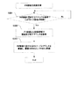
例えばDVD−R DL(Dual Layer)規格では、ファイナライズ処理にかかる時間を短縮させるため、ディスク製造メーカーによって、例えばリードインエリアや、リードアウトエリア等の緩衝用エリアにおいて、レーザ光によるプリ記録が行われている。尚、例えば緩衝用エリアのうちミドルエリアにおいては、例えばDVDレコーダー等の情報記録再生装置によってプリ記録が行われている。そこで、例えばDVD−RW DL(Dual Layer)規格でも、例えばリードインエリアや、リードアウトエリア、ミドルエリア等の緩衝用エリアにおいて、例えばレーザ光によるプリ記録を行うことを可能とする手法について提案されている。 For example, in the DVD-R DL (Dual Layer) standard, in order to shorten the time required for finalizing processing, pre-recording with a laser beam is performed by a disk manufacturer in a buffer area such as a lead-in area or a lead-out area. It has been broken. For example, in the middle area of the buffer area, pre-recording is performed by an information recording / reproducing apparatus such as a DVD recorder. Thus, for example, the DVD-RW DL (Dual Layer) standard also proposes a method that enables pre-recording with, for example, laser light in a buffer area such as a lead-in area, a lead-out area, or a middle area. ing.
しかしながら、現行のDVD−RWのコントロールデータゾーン(以下、適宜「CDZ:Control Data Zone」と称す)においては、ディスク情報及びアドレス情報等を読み取ることが可能なリーダブルエンボスピット(Readable emboss Pit、以下、適宜「エンボスピット」と称す)が形成される。このため、ディスク製造メーカーが、(i)このCDZにリーダブルエンボスピットを形成すると共に、(ii)ファイナライズ処理の際の時間短縮のために、例えばリードインエリア、リードアウトエリア、又はミドルエリア等の緩衝用エリアにおいて、プリ記録(プリライト)を行うと、ディスク製造の際の製造工程が増加するために、製造コストが上昇してしまうという技術的な問題点を有している。 However, in the control data zone of the current DVD-RW (hereinafter referred to as “CDZ: Control Data Zone” as appropriate), a readable emboss pit (hereinafter referred to as “Readable emboss Pit”) that can read disc information, address information, and the like. Where appropriate referred to as “embossed pits”. For this reason, a disc manufacturer (i) forms readable emboss pits on this CDZ, and (ii) reduces the time required for finalizing processing, such as a lead-in area, a lead-out area, or a middle area. If pre-recording (pre-write) is performed in the buffer area, the manufacturing process at the time of manufacturing the disc increases, which causes a technical problem that the manufacturing cost increases.
本発明は、例えば上述した従来の問題点に鑑みなされたものであり、例えば複数の記録層を有する情報記録媒体に対して、例えばファイナライズ処理の際の記録時間を短縮させることが可能であると共に、より適切且つ迅速に情報の記録又は再生を行うことが可能である情報記録媒体、情報記録装置及び方法、情報再生装置及び方法、並びに、コンピュータをこのような情報記録装置、及び情報再生装置として機能させるコンピュータプログラムを提供することを課題とする。 The present invention has been made in view of, for example, the above-described conventional problems. For example, for an information recording medium having a plurality of recording layers, it is possible to shorten the recording time, for example, in the finalizing process. , Information recording medium, information recording apparatus and method, information reproducing apparatus and method, and computer capable of recording or reproducing information more appropriately and quickly, and computer as such information recording apparatus and information reproducing apparatus It is an object to provide a computer program that functions.
(情報記録媒体)
以下、本発明の情報記録媒体について説明する。(Information recording medium)
Hereinafter, the information recording medium of the present invention will be described.
上記課題を解決するために、本発明の情報記録媒体は、管理情報又は緩衝用データを含む記録データを記録可能な、一又は複数の所定の記録エリア(CDZ、リードイン、ミドル、リードアウト)を有する記録層を備え、前記所定の記録エリアにおいてエンボスピットが形成されているか否かを識別する第1識別情報(EIコード)を含む前記管理情報(エンボス情報)を記録可能な管理エリア(CDZ、RMA)を備える。 In order to solve the above-described problems, the information recording medium of the present invention has one or a plurality of predetermined recording areas (CDZ, lead-in, middle, lead-out) in which recording data including management information or buffer data can be recorded. A management area (CDZ) in which the management information (emboss information) including first identification information (EI code) for identifying whether or not embossed pits are formed in the predetermined recording area can be recorded. , RMA).
本発明の情報記録媒体によれば、記録層は、(i)例えばコントロールデータゾーン等の、管理情報を記録可能な所定の記録エリア(例えば、管理エリア)、或いは、(ii)例えばリードインエリア、ミドルエリア、及びリードアウトエリア等の、ファイナライズ処理の際の緩衝用データを記録可能な所定の記録エリア(例えば、緩衝用エリア)を有する。そして、この所定の記録エリアにおいて、リーダブルエンボスピットを形成することが可能である。加えて、この記録層に備えられた管理エリアにおいては、所定の記録エリアにおいてエンボスピットが形成されているか否かを識別する第1識別情報(EIコード:Embossed Information Code)を含む管理情報を、例えばディスク製造メーカーによって、例えばエンボスピットの形成や、レーザ光のプリ記録によって予め記録可能である。 According to the information recording medium of the present invention, the recording layer has (i) a predetermined recording area (for example, management area) in which management information can be recorded, such as a control data zone, or (ii) for example a lead-in area. And a predetermined recording area (for example, a buffering area) that can record buffering data at the time of finalizing processing, such as a middle area and a lead-out area. A readable emboss pit can be formed in this predetermined recording area. In addition, in the management area provided in the recording layer, management information including first identification information (EI code: Embossed Information Code) for identifying whether or not an embossed pit is formed in a predetermined recording area, For example, recording can be performed in advance by a disc manufacturer, for example, by forming embossed pits or pre-recording with laser light.
この結果、後述される情報記録再生装置は、第1識別情報に基づいて、リーダブルエンボスピットが形成されたエリアの位置等を把握(特定)できるので、このエリアにおいては、ランドプリピットの代わりに、リーダブルエンボスピットから記録クロックを生成するように、記録クロックの生成処理を切り替えることが可能となる。概ね同様にして、リーダブルエンボスピットが形成されていないエリアにおいては、リーダブルエンボスピットの代わりに、通常の通り、ランドプリピットから記録クロックを生成するように、記録クロックの生成処理を切り替えることが可能となる。 As a result, the information recording / reproducing apparatus, which will be described later, can grasp (specify) the position or the like of the area where the readable emboss pit is formed based on the first identification information. In this area, instead of the land pre-pit, The recording clock generation processing can be switched so that the recording clock is generated from the readable emboss pit. In almost the same way, in areas where readable embossed pits are not formed, the recording clock generation process can be switched to generate recording clocks from land prepits as usual instead of readable embossed pits. It becomes.
更にこの結果、例えば情報記録再生装置は、リーダブルエンボスピットが形成されているエリアを検索するためのRFサーチや、LPPサーチを行う必要が殆ど又は完全にないので、それらのサーチに要する時間を、記録再生処理から省略することが可能となる。仮に、例えばDVD−R DL等の情報記録媒体においては、エンボスピットが形成されているか否かを識別する第1識別情報を含む管理情報は存在しない。よって、従来技術においては、記録クロックの生成処理を切り替える位置を把握(特定)するためには、情報記録再生装置自身が、当該情報記録媒体において、例えばRF信号を取得できるエリアを検索するRFサーチ、及び、例えばLPP信号を取得できるエリアを検索するLPPサーチを行う必要が生じてしまい、それらのサーチにための時間が余分に発生してしまう。これに対して、本発明では、本発明の所定の記録エリアにおいてエンボスピットが形成されているか否かを識別する第1識別情報を含む管理情報が、例えば情報記録再生装置によって取得可能であるので、RFサーチや、LPPサーチを行う必要が殆ど又は完全にないので、それらのサーチに要する時間を、記録再生処理から省略することが可能となる。 As a result, for example, the information recording / reproducing apparatus has little or no need to perform an RF search or an LPP search for searching an area where readable embossed pits are formed. It can be omitted from the recording / reproducing process. For example, in an information recording medium such as a DVD-R DL, there is no management information including first identification information for identifying whether or not an embossed pit is formed. Therefore, in the prior art, in order to ascertain (specify) the position to switch the recording clock generation process, the information recording / reproducing apparatus itself searches the information recording medium for an area where an RF signal can be acquired, for example, an RF search For example, it becomes necessary to perform an LPP search for searching an area where an LPP signal can be acquired, and extra time is required for the search. On the other hand, in the present invention, management information including first identification information for identifying whether or not embossed pits are formed in the predetermined recording area of the present invention can be acquired by, for example, an information recording / reproducing apparatus. Since there is little or no need to perform an RF search or an LPP search, the time required for these searches can be omitted from the recording / playback process.
更にこの結果、例えば情報記録再生装置は、本発明の第1識別情報に基づいて、ファイナライズ処理の際に、リーダブルエンボスピットが形成されたエリアを識別しつつ、緩衝用データを記録する領域を迅速且つ的確に把握(特定)することが可能となる。以上の結果、当該情報記録媒体のファイナライズ処理に掛かる時間の大幅な短縮や、より効率的な短縮を実現させることが可能となり、ユーザは、ファイナライズ処理において、より大きな快適性を体感することが可能となる。 As a result, for example, the information recording / reproducing apparatus quickly identifies the area where the buffer data is recorded while identifying the area where the readable embossed pit is formed in the finalizing process based on the first identification information of the present invention. It becomes possible to accurately grasp (specify). As a result, the time required for finalizing the information recording medium can be greatly reduced and more efficient, and the user can experience greater comfort in the finalizing process. It becomes.
本発明の情報記録媒体の一の態様では、前記管理情報(エンボス情報)は、前記所定の記録エリア(リードイン等)においてレーザ光によるプリ記録が行われているか否かを識別する第2識別情報(PRIコード)を含む。 In one aspect of the information recording medium of the present invention, the management information (emboss information) is a second identification for identifying whether or not pre-recording by laser light is performed in the predetermined recording area (lead-in or the like). Contains information (PRI code).
この態様によれば、例えば情報記録再生装置は、第2識別情報に加えて、第1識別情報に基づいて、ファイナライズ処理の際に、リーダブルエンボスピットが形成されたエリア、及び、レーザ光によるプリ記録が行われたエリアを識別しつつ、緩衝用データを記録する領域を迅速且つ的確に把握(特定)することが可能となる。具体的には、第1識別情報に基づいて、ディスク製造メーカーによってエンボスピットが形成され緩衝用データの記録する必要のない領域を把握(特定)することが可能である。加えて、第2識別情報に基づいて、情報記録再生装置によって例えばレーザ光によるプリ記録処理によって緩衝用データが既に記録され、ファイナライズ処理の際に緩衝用データの記録する必要のない領域を把握(特定)することが可能である。以上の結果、当該情報記録媒体のファイナライズ処理に掛かる時間の大幅な短縮や、より効率的な短縮を実現させることが可能となり、ユーザは、ファイナライズ処理において、より大きな快適性を体感することが可能となる。 According to this aspect, for example, the information recording / reproducing apparatus, in addition to the second identification information, based on the first identification information, the area where the readable emboss pits are formed and the pre-processing by the laser beam are performed in the finalizing process. It is possible to quickly and accurately grasp (specify) the area in which the buffer data is recorded while identifying the area where the recording is performed. Specifically, based on the first identification information, it is possible to grasp (specify) an area where embossed pits are formed by the disk manufacturer and where it is not necessary to record buffering data. In addition, based on the second identification information, the information recording / reproducing apparatus has already recorded the buffer data by the pre-recording process using, for example, laser light, and grasps the area where the buffer data need not be recorded during the finalizing process ( Specific). As a result, the time required for finalizing the information recording medium can be greatly reduced and more efficient, and the user can experience greater comfort in the finalizing process. It becomes.
本発明の情報記録媒体の他の態様では、前記管理情報(エンボス情報)は、前記所定の記録エリア(リードイン等)において(i)エンボスピットが形成されている、又は(ii)レーザ光によるプリ記録が行われているうち、少なくともいずれか一方であるか否かを識別する第3識別情報(PRIコード)を含む。 In another aspect of the information recording medium of the present invention, the management information (emboss information) includes (i) embossed pits formed in the predetermined recording area (lead-in, etc.), or (ii) by laser light. It includes third identification information (PRI code) for identifying whether at least one of pre-recording is being performed.
この態様によれば、例えば情報記録再生装置は、第3識別情報に基づいて、ファイナライズ処理の際に、リーダブルエンボスピットが形成されたエリア、及び、レーザ光によるプリ記録が行われたエリアを識別しつつ、緩衝用データを記録する領域を迅速且つ的確に把握(特定)することが可能となる。具体的には、第3識別情報に基づいて、ディスク製造メーカーによってエンボスピットが形成され緩衝用データの記録する必要のない領域を把握(特定)することが可能である。加えて、第3識別情報に基づいて、情報記録再生装置によって例えばレーザ光によるプリ記録処理によって緩衝用データが既に記録され、ファイナライズ処理の際に緩衝用データの記録する必要のない領域を把握(特定)することが可能である。以上の結果、当該情報記録媒体のファイナライズ処理に掛かる時間の大幅な短縮や、より効率的な短縮を実現させることが可能となり、ユーザは、ファイナライズ処理において、より大きな快適性を体感することが可能となる。 According to this aspect, for example, the information recording / reproducing apparatus identifies, on the basis of the third identification information, the area in which the readable emboss pit is formed and the area in which the pre-recording by the laser beam is performed in the finalizing process. However, it is possible to quickly and accurately grasp (specify) the area in which the buffer data is recorded. Specifically, based on the third identification information, it is possible to grasp (specify) an area where embossed pits are formed by the disk manufacturer and where it is not necessary to record buffer data. In addition, based on the third identification information, the information recording / reproducing apparatus has already recorded the buffer data, for example, by the pre-recording process using laser light, and grasps the area where the buffer data need not be recorded during the finalizing process ( Specific). As a result, the time required for finalizing the information recording medium can be greatly reduced and more efficient, and the user can experience greater comfort in the finalizing process. It becomes.
本発明の情報記録媒体の他の態様では、前記管理情報(エンボス情報)は、前記所定の記録エリア(リードイン等)において、(i)エンボスピットが形成されている位置、又は(ii)レーザ光によるプリ記録が行われている位置を特定可能な位置情報を含む。 In another aspect of the information recording medium of the present invention, the management information (emboss information) includes (i) a position where an emboss pit is formed or (ii) a laser in the predetermined recording area (lead-in or the like). Position information that can identify the position where pre-recording by light is performed is included.
この態様によれば、例えば情報記録再生装置は、第1識別情報に加えて位置情報に基づいて、例えばファイナライズ処理の際に、緩衝用データを記録する領域を高精度且つ的確に把握(特定)することが可能となる。 According to this aspect, for example, the information recording / reproducing apparatus grasps (specifies) the area for recording the buffer data with high accuracy and accuracy based on the position information in addition to the first identification information, for example, in the finalizing process. It becomes possible to do.
本発明の情報記録媒体の他の態様では、前記第1識別情報(EIコード)は、(i)前記所定の記録エリアの少なくとも一部において、エンボスピットが形成されているか否かを識別可能である、又は(ii)前記所定の記録エリアの一部において、エンボスピットが形成されているか、若しくは前記所定の記録エリアの全部において、エンボスピットが形成されているか否かを識別可能である。 In another aspect of the information recording medium of the present invention, the first identification information (EI code) can identify (i) whether or not an embossed pit is formed in at least a part of the predetermined recording area. It is possible to identify whether or not (ii) an embossed pit is formed in a part of the predetermined recording area, or whether an embossed pit is formed in the entire predetermined recording area.
この態様によれば、例えば情報記録再生装置は、第1識別情報に加えて位置情報に基づいて、例えばファイナライズ処理の際に、緩衝用データを記録する領域を、所定の記録エリアの一部又は全部である、より明確且つ細分化された記録領域に基づいて、高精度且つ的確に把握(特定)することが可能となる。 According to this aspect, for example, the information recording / reproducing apparatus sets, on the basis of the position information in addition to the first identification information, for example, in the finalization process, the area for recording the buffer data as a part of the predetermined recording area or It is possible to grasp (specify) accurately and accurately based on all the clearer and more detailed recording areas.
本発明の情報記録媒体の他の態様では、少なくとも前記第1識別情報(EIコード)は、所定のビットパターンで、複数の前記所定の記録エリアにおいて、エンボスピットが形成されているか否かを識別可能である。 In another aspect of the information recording medium of the present invention, at least the first identification information (EI code) identifies whether or not embossed pits are formed in a plurality of the predetermined recording areas with a predetermined bit pattern. Is possible.
この態様によれば、例えば後述される情報記録再生装置は、所定のビットパターンに基づいて、より迅速且つ高精度に、複数の所定の記録エリアにおいて、エンボスピットが形成されているか否かを識別することが可能である。 According to this aspect, for example, an information recording / reproducing apparatus to be described later identifies whether or not embossed pits are formed in a plurality of predetermined recording areas more quickly and accurately based on a predetermined bit pattern. Is possible.
本発明の情報記録媒体の他の態様では、前記管理情報(エンボス情報)は、前記管理エリアにおいて、(i)エンボスピットの形成によって、又は(ii)レーザ光のプリ記録によって、予め記録されている。 In another aspect of the information recording medium of the present invention, the management information (emboss information) is pre-recorded in the management area by (i) formation of emboss pits or (ii) by pre-recording of laser light. Yes.
この態様によれば、例えばディスク製造メーカーによる管理情報の記録を簡便にすることが可能である。 According to this aspect, it is possible to simplify the recording of management information by a disk manufacturer, for example.
本発明の情報記録媒体の他の態様では、前記所定の記録エリアは、コントロールデータゾーン、リードインエリア、ミドルエリア、及び、リードアウトエリアのうち少なくとも一のエリアである。 In another aspect of the information recording medium of the present invention, the predetermined recording area is at least one of a control data zone, a lead-in area, a middle area, and a lead-out area.
この態様によれば、例えば、情報記録再生装置による、ファイナライズ処理をより簡便にすることが可能である。 According to this aspect, for example, the finalizing process by the information recording / reproducing apparatus can be simplified.
本発明の情報記録媒体の他の態様では、前記管理情報(エンボス情報)は、前記所定の記録エリアに隣接する、前記記録情報を読み取ることができないアンリーダブルエンボスピットが形成されている読取不能エリアの記録容量(16ECCブロック)に関する情報を含む。 In another aspect of the information recording medium of the present invention, the management information (emboss information) is an unreadable area adjacent to the predetermined recording area where an unreadable embossed pit that cannot read the recorded information is formed. Contains information about the recording capacity (16ECC blocks).
この態様によれば、例えば情報記録再生装置は、リーダブルエンボスピットが形成されたエリアの位置と、このエリアに隣接するアンリーダブルエンボスピットが形成されたエリアの位置とを把握(特定)できる。従って、仮にアンリーダブルエンボスピットが形成されたエリアにおいて、例えば再生エラーが発生しアドレス情報を取得できなかった場合でも、情報記録再生装置は、このエリアにおいて発生する再生エラーを予見して無視する等のフェイルセーフ処理を含む記録再生動作を実現することが可能となる。 According to this aspect, for example, the information recording / reproducing apparatus can grasp (specify) the position of the area where the readable embossed pit is formed and the position of the area where the unreadable embossed pit adjacent to this area is formed. Therefore, even if, for example, a reproduction error occurs and the address information cannot be acquired in the area where the unreadable emboss pit is formed, the information recording / reproducing apparatus foresees and ignores the reproduction error occurring in this area. The recording / reproducing operation including the fail-safe process can be realized.
(情報記録装置)
以下、本発明の情報記録装置について説明する。(Information recording device)
The information recording apparatus of the present invention will be described below.
上記課題を解決するために、本発明の情報記録装置は、上述した本発明の情報記録媒体(但し、その各種態様を含む)に前記記録データを記録する情報記録装置であって、前記管理エリアから前記管理情報を取得する取得手段と、前記記録データを記録する記録手段と、取得された前記管理情報に基づいて、前記記録データを記録するように前記記録手段を制御する制御手段とを備える。 In order to solve the above problems, an information recording apparatus of the present invention is an information recording apparatus for recording the recording data on the above-described information recording medium of the present invention (including various aspects thereof), wherein the management area Acquisition means for acquiring the management information from, recording means for recording the recording data, and control means for controlling the recording means to record the recording data based on the acquired management information. .
本発明の情報記録装置によれば、先ず、取得手段によって、例えば第1識別情報や第2識別情報を含む管理情報が取得される。次に、制御手段の制御下で、記録手段は、例えばファイナライズ処理の際の緩衝用データを含む記録データを記録する。 According to the information recording apparatus of the present invention, first, management information including, for example, first identification information and second identification information is acquired by the acquisition unit. Next, under the control of the control means, the recording means records recording data including, for example, buffering data at the time of finalizing processing.
この結果、情報記録装置は、第1識別情報に基づいて、リーダブルエンボスピットが形成されたエリアの位置等を把握(特定)できるので、このエリアにおいては、ランドプリピットの代わりに、リーダブルエンボスピットから記録クロックを生成するように、記録クロックの生成処理を切り替えることが可能となる。概ね同様にして、リーダブルエンボスピットが形成されていないエリアにおいては、リーダブルエンボスピットの代わりに、通常の通り、ランドプリピットから記録クロックを生成するように、記録クロックの生成処理を切り替えることが可能となる。 As a result, the information recording apparatus can grasp (specify) the position and the like of the area where the readable embossed pit is formed based on the first identification information. In this area, instead of the land prepit, the readable embossed pit The recording clock generation process can be switched so that the recording clock is generated from the recording clock. In almost the same way, in areas where readable embossed pits are not formed, the recording clock generation process can be switched to generate recording clocks from land prepits as usual instead of readable embossed pits. It becomes.
更にこの結果、情報記録装置は、リーダブルエンボスピットが形成されているエリアを検索するためのRFサーチや、LPPサーチを行う必要が殆ど又は完全にないので、それらのサーチに要する時間を、記録処理から省略することが可能となる。 As a result, the information recording apparatus has little or no need to perform an RF search or an LPP search for searching for an area where readable embossed pits are formed. Can be omitted.
更にこの結果、情報記録装置は、例えば第1識別情報や第2識別情報に基づいて、ファイナライズ処理の際に、リーダブルエンボスピットが形成されたエリアを識別しつつ、緩衝用データを記録する領域を迅速且つ的確に把握(特定)することが可能となる。以上の結果、当該情報記録媒体のファイナライズ処理に掛かる時間の大幅な短縮や、より効率的な短縮を実現させることが可能となり、ユーザは、ファイナライズ処理において、より大きな快適性を体感することが可能となる。 Further, as a result, the information recording apparatus identifies an area in which buffer data is recorded while identifying the area where the readable emboss pit is formed, for example, in the finalizing process based on the first identification information or the second identification information. It becomes possible to grasp (specify) quickly and accurately. As a result, the time required for finalizing the information recording medium can be greatly reduced and more efficient, and the user can experience greater comfort in the finalizing process. It becomes.
尚、上述した本発明の情報記録媒体が有する各種態様に対応して、本発明の情報記録装置も各種態様を採ることが可能である。 Incidentally, in response to the various aspects of the information recording medium of the present invention described above, the information recording apparatus of the present invention can also adopt various aspects.
本発明の情報記録装置の一の態様では、前記記録データの記録に基づいて、前記管理情報を更新する更新手段を更に備える。 In one aspect of the information recording apparatus of the present invention, the information recording apparatus further includes an updating unit that updates the management information based on the recording of the recording data.
この態様によれば、情報記録装置は、記録データが記録された記録領域の最新の状態を反映しつつ、更新された管理情報に基づいて、例えばファイナライズ処理の際に、緩衝用データを記録する領域を迅速且つ的確に把握(特定)することが可能となる。 According to this aspect, the information recording apparatus records the buffer data in the finalizing process, for example, based on the updated management information while reflecting the latest state of the recording area in which the recording data is recorded. It becomes possible to grasp (identify) the area quickly and accurately.
本発明の情報記録装置の他の態様では、前記制御手段は、ファイナライズ処理の際の緩衝用データを記録するように、前記記録手段を制御する。 In another aspect of the information recording apparatus of the present invention, the control means controls the recording means so as to record buffer data at the time of finalizing processing.
この態様によれば、情報記録装置は、管理情報に基づいて、ファイナライズ処理の際に、緩衝用データを記録する領域を迅速且つ的確に把握(特定)することが可能となる。 According to this aspect, the information recording apparatus can quickly and accurately grasp (specify) the area in which the buffer data is recorded, based on the management information, during the finalizing process.
本発明の情報記録装置の他の態様では、前記制御手段は、プリ記録処理の際の緩衝用データを記録するように、前記記録手段を制御する。 In another aspect of the information recording apparatus of the present invention, the control means controls the recording means so as to record buffer data for pre-recording processing.
この態様によれば、情報記録装置は、管理情報に基づいて、プリ記録処理の際に、緩衝用データを記録する領域を迅速且つ的確に把握(特定)することが可能となる。 According to this aspect, the information recording device can quickly and accurately grasp (specify) the area in which the buffer data is recorded based on the management information during the pre-recording process.
(情報再生装置)
以下、本発明の情報再生装置について説明する。(Information playback device)
The information reproducing apparatus of the present invention will be described below.
上記課題を解決するために、本発明の情報再生装置は、上述した本発明の情報記録媒体(但し、その各種態様を含む)から前記記録データを再生する情報再生装置であって、前記管理エリアから前記管理情報を取得する取得手段と、前記記録データを再生する再生手段と、取得された前記管理情報に基づいて、前記記録データを再生するように前記再生手段を制御する制御手段とを備える。 In order to solve the above problems, an information reproducing apparatus of the present invention is an information reproducing apparatus for reproducing the recorded data from the above-described information recording medium of the present invention (including various aspects thereof), wherein the management area Acquisition means for acquiring the management information from, reproduction means for reproducing the recorded data, and control means for controlling the reproduction means to reproduce the recorded data based on the acquired management information. .
本発明の情報再生装置によれば、先ず、取得手段によって、例えば第1識別情報や第2識別情報を含む管理情報が取得される。次に、制御手段の制御下で、再生手段は、例えば管理情報を含む記録データを再生する。 According to the information reproducing apparatus of the present invention, first, management information including, for example, first identification information and second identification information is acquired by the acquisition unit. Next, under the control of the control means, the reproduction means reproduces, for example, recorded data including management information.
この結果、情報再生装置は、第1識別情報に基づいて、リーダブルエンボスピットが形成されたエリアの位置等を把握(特定)できるので、このエリアにおいては、ランドプリピットの代わりに、リーダブルエンボスピットから再生クロックを生成するように、再生クロックの生成処理を切り替えることが可能となる。概ね同様にして、リーダブルエンボスピットが形成されていないエリアにおいては、リーダブルエンボスピットの代わりに、通常の通り、ランドプリピットから再生クロックを生成するように、再生クロックの生成処理を切り替えることが可能となる。 As a result, the information reproducing apparatus can grasp (specify) the position and the like of the area where the readable embossed pit is formed based on the first identification information. In this area, instead of the land prepit, the readable embossed pit Thus, it is possible to switch the generation process of the reproduction clock so as to generate the reproduction clock. In almost the same way, in areas where readable embossed pits are not formed, playback clock generation processing can be switched to generate playback clocks from land prepits as usual instead of readable embossed pits. It becomes.
更にこの結果、情報再生装置は、リーダブルエンボスピットが形成されているエリアを検索するためのRFサーチや、LPPサーチを行う必要が殆ど又は完全にないので、それらのサーチに要する時間を、再生処理から省略することが可能となる。 As a result, the information reproducing apparatus has little or no need to perform an RF search or an LPP search for searching an area where readable embossed pits are formed. Can be omitted.
尚、上述した本発明の情報記録媒体が有する各種態様に対応して、本発明の情報再生装置も各種態様を採ることが可能である。 Incidentally, in response to the various aspects of the information recording medium of the present invention described above, the information reproducing apparatus of the present invention can also adopt various aspects.
(情報記録方法)
以下、本発明の情報記録方法について説明する。(Information recording method)
Hereinafter, the information recording method of the present invention will be described.
上記課題を解決するために、本発明の情報記録方法は、上述した本発明の情報記録媒体(但し、その各種態様を含む)に前記記録データを記録する記録手段を備える情報記録装置における情報記録方法であって、前記管理エリアから前記管理情報を取得する取得工程と、取得された前記管理情報に基づいて、前記記録データを記録するように前記記録手段を制御する制御工程とを備える。 In order to solve the above-mentioned problems, an information recording method of the present invention provides an information recording apparatus comprising an information recording apparatus for recording the recording data on the above-described information recording medium of the present invention (including various aspects thereof). A method comprising: an acquisition step of acquiring the management information from the management area; and a control step of controlling the recording means so as to record the recording data based on the acquired management information.
本発明の情報記録方法によれば、上述した本発明の情報記録装置が有する各種利益を享受することが可能となる。 According to the information recording method of the present invention, it is possible to receive various benefits of the above-described information recording apparatus of the present invention.
尚、上述した本発明の情報記録装置が有する各種態様に対応して、本発明の情報記録方法も各種態様を採ることが可能である。 Incidentally, in response to the various aspects of the information recording apparatus of the present invention described above, the information recording method of the present invention can also adopt various aspects.
(情報再生方法)
以下、本発明の情報再生方法について説明する。(Information playback method)
The information reproducing method of the present invention will be described below.
上記課題を解決するために、本発明の情報再生方法は、上述した本発明の情報記録媒体(但し、その各種態様を含む)から前記記録データを再生する再生手段を備える情報再生装置における情報再生方法であって、前記管理エリアから前記管理情報を取得する取得工程と、取得された前記管理情報に基づいて、前記記録データを再生するように前記再生手段を制御する制御工程とを備える。 In order to solve the above-mentioned problems, an information reproducing method of the present invention provides information reproduction in an information reproducing apparatus comprising reproducing means for reproducing the recorded data from the above-described information recording medium of the present invention (including various aspects thereof). A method comprising: an acquisition step of acquiring the management information from the management area; and a control step of controlling the reproduction means to reproduce the recorded data based on the acquired management information.
本発明の情報再生方法によれば、上述した本発明の情報再生装置が有する各種利益を享受することが可能となる。 According to the information reproducing method of the present invention, it is possible to enjoy various benefits of the above-described information reproducing apparatus of the present invention.
尚、上述した本発明の情報再生装置が有する各種態様に対応して、本発明の情報再生方法も各種態様を採ることが可能である。 Incidentally, in response to the various aspects of the information reproducing apparatus of the present invention described above, the information reproducing method of the present invention can also adopt various aspects.
(コンピュータプログラム)
以下、本発明のコンピュータプログラムについて説明する。(Computer program)
Hereinafter, the computer program of the present invention will be described.
上記課題を解決するために、本発明の記録制御用のコンピュータプログラムは、上述した本発明の情報記録装置(但し、その各種態様を含む)に備えられたコンピュータを制御する記録制御用のコンピュータプログラムであって、該コンピュータを、前記取得手段、前記記録手段、及び、前記制御手段のうち少なくとも一部として機能させる。 In order to solve the above problems, a computer program for recording control of the present invention is a computer program for recording control for controlling a computer provided in the above-described information recording apparatus of the present invention (including various aspects thereof). Then, the computer is caused to function as at least a part of the acquisition unit, the recording unit, and the control unit.
上記課題を解決するために、本発明の再生制御用のコンピュータプログラムは、上述した本発明の情報再生装置(但し、その各種態様を含む)に備えられたコンピュータを制御する再生制御用のコンピュータプログラムであって、該コンピュータを、前記取得手段、前記再生手段、及び、前記制御手段のうち少なくとも一部として機能させる。 In order to solve the above problems, a computer program for reproduction control according to the present invention is a computer program for reproduction control that controls a computer provided in the above-described information reproduction apparatus according to the present invention (including various aspects thereof). Then, the computer is caused to function as at least a part of the acquisition unit, the reproduction unit, and the control unit.
本発明に係るコンピュータプログラムによれば、当該コンピュータプログラムを格納するROM、CD−ROM、DVD−ROM、ハードディスク等の記録媒体から、当該コンピュータプログラムをコンピュータに読み込んで実行させれば、或いは、当該コンピュータプログラムを、通信手段を介してコンピュータにダウンロードさせた後に実行させれば、上述した本発明の情報記録装置、及び情報再生装置を比較的簡単に実現できる。 According to the computer program of the present invention, the computer program is read from a recording medium such as a ROM, a CD-ROM, a DVD-ROM, and a hard disk that stores the computer program, and executed, or the computer If the program is downloaded to a computer via communication means and then executed, the above-described information recording apparatus and information reproducing apparatus of the present invention can be realized relatively easily.
尚、上述した本発明の情報記録装置、及び情報再生装置における各種態様に対応して、本発明の各コンピュータプログラムも各種態様を採ることが可能である。 Incidentally, in response to various aspects of the information recording apparatus and information reproducing apparatus of the present invention described above, each computer program of the present invention can also adopt various aspects.
上記課題を解決するために、コンピュータ読取可能な媒体内の第1コンピュータプログラム製品は、上述した本発明の情報記録装置(但し、その各種態様を含む)に備えられたコンピュータにより実行可能なプログラム命令を明白に具現化し、該コンピュータを、前記取得手段、前記記録手段、及び、前記制御手段のうち少なくとも一部として機能させる。 In order to solve the above problems, a first computer program product in a computer-readable medium is a program instruction executable by a computer provided in the above-described information recording apparatus of the present invention (including various aspects thereof). Is clearly realized, and the computer is caused to function as at least a part of the acquisition unit, the recording unit, and the control unit.
上記課題を解決するために、コンピュータ読取可能な媒体内の第2コンピュータプログラム製品は、上述した本発明の情報再生装置(但し、その各種態様を含む)に備えられたコンピュータにより実行可能なプログラム命令を明白に具現化し、該コンピュータを、前記取得手段、前記再生手段、及び、前記制御手段のうち少なくとも一部として機能させる。 In order to solve the above problems, a second computer program product in a computer-readable medium is a program instruction executable by a computer provided in the above-described information reproducing apparatus of the present invention (including various aspects thereof). Is clearly embodied, and the computer is caused to function as at least a part of the acquisition unit, the reproduction unit, and the control unit.
本発明の第1又は第2コンピュータプログラム製品によれば、当該コンピュータプログラム製品を格納するROM、CD−ROM、DVD−ROM、ハードディスク等の記録媒体から、当該コンピュータプログラム製品をコンピュータに読み込めば、或いは、例えば伝送波である当該コンピュータプログラム製品を、通信手段を介してコンピュータにダウンロードすれば、上述した本発明の情報記録装置又は情報再生装置を比較的容易に実施可能となる。更に具体的には、当該コンピュータプログラム製品は、上述した本発明の情報記録装置又は情報再生装置として機能させるコンピュータ読取可能なコード(或いはコンピュータ読取可能な命令)から構成されてよい。 According to the first or second computer program product of the present invention, if the computer program product is read into a computer from a recording medium such as a ROM, CD-ROM, DVD-ROM, hard disk or the like storing the computer program product, or For example, if the computer program product, which is a transmission wave, is downloaded to a computer via communication means, the above-described information recording apparatus or information reproducing apparatus of the present invention can be implemented relatively easily. More specifically, the computer program product may be configured by a computer-readable code (or computer-readable instruction) that functions as the above-described information recording apparatus or information reproducing apparatus of the present invention.
本発明のこのような作用及び他の利得は次に説明する実施例から明らかにされる。 These effects and other advantages of the present invention will become apparent from the embodiments described below.
以上説明したように、本発明の情報記録媒体によれば、一又は複数の所定の記録エリアを有する記録層を備え、この所定の記録エリアにおいてエンボスピットが形成されているか否かを識別する第1識別情報やプリ記録されているか否かを識別する第2識別情報を含む管理情報を記録可能な管理エリア(CDZ、RMA)を備える。この結果、例えば情報記録再生装置は、本発明の第1識別情報や第2識別情報に基づいて、ファイナライズ処理の際に、リーダブルエンボスピットが形成されたエリアを識別しつつ、緩衝用データを記録する領域を迅速且つ的確に把握(特定)することが可能となる。以上の結果、当該情報記録媒体のファイナライズ処理に掛かる時間の大幅な短縮や、より効率的な短縮を実現させることが可能となり、ユーザは、ファイナライズ処理において、より大きな快適性を体感することが可能となる。 As described above, according to the information recording medium of the present invention, the recording layer having one or a plurality of predetermined recording areas is provided, and whether or not the embossed pit is formed in the predetermined recording area is identified. A management area (CDZ, RMA) capable of recording management information including first identification information and second identification information for identifying whether or not pre-recording is provided. As a result, for example, the information recording / reproducing apparatus records the buffering data while identifying the area where the readable embossed pit is formed in the finalizing process based on the first identification information and the second identification information of the present invention. It is possible to grasp (specify) the area to be performed quickly and accurately. As a result, the time required for finalizing the information recording medium can be greatly reduced and more efficient, and the user can experience greater comfort in the finalizing process. It becomes.
また、本発明の情報記録装置及び方法によれば、取得手段及び工程、記録手段及び工程、並びに、制御手段及び工程を備える。この結果、情報記録装置は、第1識別情報に基づいて、リーダブルエンボスピットが形成されたエリアの位置等を把握(特定)できるので、このエリアにおいては、ランドプリピットの代わりに、リーダブルエンボスピットから記録クロックを生成するように、記録クロックの生成処理を切り替えることが可能となる。概ね同様にして、リーダブルエンボスピットが形成されていないエリアにおいては、リーダブルエンボスピットの代わりに、通常の通り、ランドプリピットから記録クロックを生成するように、記録クロックの生成処理を切り替えることが可能となる。 In addition, according to the information recording apparatus and method of the present invention, the information recording apparatus and method include an acquisition unit and process, a recording unit and process, and a control unit and process. As a result, the information recording apparatus can grasp (specify) the position and the like of the area where the readable embossed pit is formed based on the first identification information. In this area, instead of the land prepit, the readable embossed pit The recording clock generation process can be switched so that the recording clock is generated from the recording clock. In almost the same way, in areas where readable embossed pits are not formed, the recording clock generation process can be switched to generate recording clocks from land prepits as usual instead of readable embossed pits. It becomes.
また、本発明の情報再生装置及び方法によれば、取得手段及び工程、再生手段及び工程、並びに、制御手段及び工程を備える。この結果、情報再生装置は、第1識別情報に基づいて、リーダブルエンボスピットが形成されたエリアの位置等を把握(特定)できるので、このエリアにおいては、ランドプリピットの代わりに、リーダブルエンボスピットから再生クロックを生成するように、再生クロックの生成処理を切り替えることが可能となる。概ね同様にして、リーダブルエンボスピットが形成されていないエリアにおいては、リーダブルエンボスピットの代わりに、通常の通り、ランドプリピットから再生クロックを生成するように、再生クロックの生成処理を切り替えることが可能となる。 In addition, according to the information reproducing apparatus and method of the present invention, the information reproducing apparatus and method include an obtaining unit and process, a reproducing unit and process, and a control unit and process. As a result, the information reproducing apparatus can grasp (specify) the position and the like of the area where the readable embossed pit is formed based on the first identification information. In this area, instead of the land prepit, the readable embossed pit Thus, it is possible to switch the generation process of the reproduction clock so as to generate the reproduction clock. In almost the same way, in areas where readable embossed pits are not formed, playback clock generation processing can be switched to generate playback clocks from land prepits as usual instead of readable embossed pits. It becomes.
更に、また、本発明のコンピュータプログラムによれば、コンピュータを上述した本発明の情報記録装置、及び情報再生装置として機能させるので、上述した、例えばDVD−RW DL(Dual Layer)の光ディスク等の書き換え型の光ディスクに対して、情報記録装置、及び情報再生装置は、第1識別情報に基づいて、リーダブルエンボスピットが形成されたエリアの位置等を把握(特定)できるので、このエリアにおいては、ランドプリピットの代わりに、リーダブルエンボスピットから記録又は再生クロックを生成するように、記録又は再生クロックの生成処理を切り替えることが可能となる。概ね同様にして、リーダブルエンボスピットが形成されていないエリアにおいては、リーダブルエンボスピットの代わりに、通常の通り、ランドプリピットから記録又は再生クロックを生成するように、記録又は再生クロックの生成処理を切り替えることが可能となる。 Furthermore, according to the computer program of the present invention, since the computer functions as the above-described information recording apparatus and information reproducing apparatus of the present invention, rewriting of the above-described DVD-RW DL (Dual Layer) optical disk or the like, for example, Since the information recording device and the information reproducing device can grasp (specify) the position and the like of the area where the readable embossed pit is formed based on the first identification information with respect to the type of optical disc, It is possible to switch the recording or reproduction clock generation process so that the recording or reproduction clock is generated from the readable embossed pit instead of the pre-pit. In a similar manner, in the area where the readable emboss pit is not formed, instead of the readable emboss pit, the recording or playback clock generation processing is performed so that the recording or playback clock is generated from the land pre-pit as usual. It is possible to switch.
1…センターホール、10…トラック、11…ECCブロック、50…管理情報、50a…エンボス情報、50b(50e)…PR情報、51a…EIコード、51b(51e)…PRIコード、100…光ディスク、101…リードインエリア、102…データエリア、103…リードアウトエリア、104…ミドルエリア、104s…シフトミドルエリア、300…情報記録再生装置、301…光ピックアップ、302…信号記録再生手段、303…アドレス検出部、305…CPU(ドライブ制御手段)、306…スピンドルモータ、307(402)…メモリ、308(406)…データ入出力制御手段、309(407)…バス、400…ホストコンピュータ、401…CPU(ホスト用)、403…操作制御手段、404…操作ボタン、405…表示パネル、CDZ…コントロールデータゾーン、RMA…レコーディングマネージメントエリア、LB…レーザ光
DESCRIPTION OF
以下、本発明を実施するための最良の形態について実施例毎に順に図面に基づいて説明する。 Hereinafter, the best mode for carrying out the present invention will be described for each embodiment in order with reference to the drawings.
(1)情報記録媒体の実施例
次に、図1から図7を参照して、本発明の情報記録媒体の実施例について詳細に説明する。(1) Embodiment of Information Recording Medium Next, an embodiment of the information recording medium of the present invention will be described in detail with reference to FIGS.
(1−1)基本構成
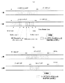
先ず図1を参照して、本発明の情報記録媒体の実施例に係る光ディスクの基本構造について説明する。ここに、図1は、本発明の情報記録媒体の実施例に係る複数の記録領域を有する光ディスクの基本構造を示した概略平面図(図1(a))、及び、該光ディスクの概略断面図に対応付けられた、その半径方向における記録領域構造の図式的概念図(図1(b))である。尚、本実施例に係る光ディスクにおいては、L0層のトラックパスと、L1層のトラックパスとが反対の記録方向であるオポジット方式が記録方式の一具体例として採用されている。(1-1) Basic Configuration First, the basic structure of an optical disc according to an embodiment of the information recording medium of the present invention will be described with reference to FIG. FIG. 1 is a schematic plan view (FIG. 1 (a)) showing a basic structure of an optical disc having a plurality of recording areas according to an embodiment of the information recording medium of the present invention, and a schematic cross-sectional view of the optical disc. FIG. 2 is a schematic conceptual diagram (FIG. 1B) of a recording area structure in the radial direction associated with FIG. In the optical disc according to the present embodiment, the opposite method in which the L0 layer track path and the L1 layer track path are in opposite recording directions is adopted as a specific example of the recording method.
図1(a)及び図1(b)に示されるように、光ディスク100は、例えば、DVDと同じく直径12cm程度のディスク本体上の記録面に、センターホール1を中心として本実施例に係るリードインエリア101又はリードアウトエリア103、データエリア102、並びに、ミドルエリア104が設けられている。そして、光ディスク100の例えば、透明基板106に、L0層及びL1層等の記録層が積層されている。そして、この記録層の各記録領域には、例えば、センターホール1を中心にスパイラル状或いは同心円状に、例えば、グルーブトラック及びランドトラック等のトラック10が交互に設けられている。また、このトラック10上には、データがECC(Error Correction Code)ブロック11という単位で分割されて記録される。ECCブロック11は、記録情報がエラー訂正可能なデータ管理単位である。
As shown in FIGS. 1 (a) and 1 (b), an
尚、本発明は、このような三つのエリアを有する光ディスクには特に限定されない。例えば、リードインエリア101又はリードアウトエリア103、並びにミドルエリア104が存在せずとも、以下に説明するデータ構造等の構築は可能である。また、後述するように、リードインエリア101又はリードアウト103、並びにミドルエリア104は更に細分化された構成であってもよい。
The present invention is not particularly limited to an optical disc having such three areas. For example, even if the lead-in
本実施例に係る光ディスク100は、図1(b)に示されるように、例えば、透明基板106に、後述される本発明に係る第1及び第2記録層の一例を構成するL0層及びL1層が積層された構造をしている。このような二層型の光ディスク100の記録再生時には、図1(b)中、下側から上側に向かって照射されるレーザ光LBの集光位置をいずれの記録層に合わせるかに応じて、L0層における記録再生が行なわれるか又はL1層における記録再生が行われる。また、本実施例に係る光ディスク100は、2層片面、即ち、デュアルレイヤに限定されるものではなく、2層両面、即ちデュアルレイヤーダブルサイドであってもよい。更に、上述の如く2層の記録層を有する光ディスクに限られることなく、3層以上の多層型の光ディスクであってもよい。尚、2層型光ディスクにおけるオポジット方式による記録又は再生手順、並びに、各層におけるデータ構造については、後述される。
As shown in FIG. 1B, the
(1−2)詳細構成
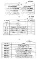
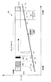
次に、図2及び図3を参照して、本発明の情報記録媒体の実施例に係る2層型光ディスクの詳細構成について説明する。より具体的には、図2及び図3を参照して、2層型光ディスクのデータ構造、該光ディスクの記録領域におけるECCブロックを構成する物理的セクタ番号等のアドレス、並びに、該光ディスクのオポジット方式による記録又は再生手順について説明する。ここに、図2は、本発明の情報記録媒体の実施例に係る2層型光ディスクのデータ構造及び該光ディスクの記録領域におけるECCブロックを構成する物理的セクタ番号等のアドレス、並びに、該光ディスクのオポジット方式による記録又は再生方法を示した概念的グラフである。図3は、本発明の情報記録媒体の内周側及び外周側においてリーダブルエンボスピットが形成可能なエリアを図式的に示した模式図である。尚、図2中の縦軸は、例えば16進数で表現されたセクタ番号等のアドレスを示し、横軸は、光ディスクの半径方向の相対的な位置を示す。(1-2) Detailed Configuration Next, with reference to FIG. 2 and FIG. 3, the detailed configuration of the two-layer optical disc according to the embodiment of the information recording medium of the present invention will be described. More specifically, referring to FIG. 2 and FIG. 3, the data structure of the two-layer type optical disc, the address such as the physical sector number constituting the ECC block in the recording area of the optical disc, and the opposite method of the optical disc A recording or reproducing procedure according to the above will be described. FIG. 2 shows the data structure of the two-layer optical disc according to the embodiment of the information recording medium of the present invention, the address such as the physical sector number constituting the ECC block in the recording area of the optical disc, and the optical disc 3 is a conceptual graph showing a recording or reproducing method by an opposite method. FIG. 3 is a schematic diagram schematically showing areas where readable emboss pits can be formed on the inner and outer peripheral sides of the information recording medium of the present invention. Note that the vertical axis in FIG. 2 indicates an address such as a sector number expressed in hexadecimal, for example, and the horizontal axis indicates a relative position in the radial direction of the optical disk.
図2に示されるように、本発明の情報記録媒体の実施例に係る2層型光ディスク100は、図示しない透明基板に積層された2層の記録層、即ち、L0層とL1層とを備えて構成されている。具体的には、L0層には、内周側から外周側にかけて、レコーディングマネージメントエリア(Recording Management Area)RMA0、リードインエリア101−0、データエリア102−0、及びミドルエリア104−0が設けられている。尚、例えばリードインエリア、ミドルエリア、及びリードアウトエリア等のファイナライズ処理の際の緩衝用データを記録可能な緩衝用エリアによって、本発明に係る「所定の記録エリア」の一の例が構成されている。
As shown in FIG. 2, a two-layer
RMA0(及び、後述されるRMA1)においては、本発明に係る「管理情報」の一例を構成するRMD(Recording Management Data)が記録可能である。詳細には、RMA0(RMA1)においては、RMDが、約818回程度追記することが可能である。このRMA0(RMA1)によって、本願発明に係る「管理エリア」の一例、又は、「所定の記録エリア」の他の例が構成されている。 In RMA0 (and RMA1 described later), RMD (Recording Management Data) constituting an example of “management information” according to the present invention can be recorded. Specifically, in RMA0 (RMA1), RMD can be additionally written about 818 times. This RMA0 (RMA1) constitutes an example of “management area” according to the present invention or another example of “predetermined recording area”.
リードインエリア101−0には、コントロールデータゾーンCDZが設けられている。このコントロールデータゾーンCDZには、例えば記録層の数や記録トラックの方向やトラックピッチ等の各種情報が、例えばエンボスピットにより予め形成される、あるいはレーザ光等によってプリ記録される。データエリア102−0には、記録情報が記録可能である。ミドルエリア104−0は、L0層及びL1層に対する記録又は再生位置が未記録領域や基板外へ外れることを防止する基本機能を有するが、層間ジャンプの際に記録又は再生位置が未記録領域や基板外に外れることを防止する、言わば「ジャンプ緩衝用エリア」としての機能も有する。 A control data zone CDZ is provided in the lead-in area 101-0. In the control data zone CDZ, for example, various information such as the number of recording layers, the direction of recording tracks, and the track pitch are formed in advance by embossed pits or pre-recorded by laser light or the like. Recording information can be recorded in the data area 102-0. The middle area 104-0 has a basic function of preventing the recording or reproducing position with respect to the L0 layer and the L1 layer from moving out of the unrecorded area or the substrate. It also has a function as a “jump buffer area” for preventing it from coming out of the substrate.
他方、L1層には、外周側から内周側にかけて、ミドルエリア104−1、データエリア102−1、リードアウトエリア103−1、及び、RMA1が設けられている。より詳細には、RMA0(RMA1)と、図示しないレーザ光のパワーキャリブレーションを行う較正用エリアとを合わせて「R-Information Area」と称しても良い。また、上述したリードインエリア101−0、データエリア102−0(102−1)、ミドルエリア104−0(104−1)、及びリードアウトエリア103−1を合わせて「Information Area」と称しても良い。 On the other hand, in the L1 layer, a middle area 104-1, a data area 102-1, a lead-out area 103-1, and RMA1 are provided from the outer peripheral side to the inner peripheral side. More specifically, RMA0 (RMA1) and a calibration area for performing laser beam power calibration (not shown) may be collectively referred to as an “R-Information Area”. The lead-in area 101-0, the data area 102-0 (102-1), the middle area 104-0 (104-1), and the lead-out area 103-1 are collectively referred to as an “Information Area”. Also good.
以上のように2層型光ディスク100は構成されているので、該光ディスク100の記録又は再生の際には、後述される本発明の情報記録装置の一具体例に係る情報記録再生装置の光ピックアップ等によって、レーザ光LBは、図示しない基板の側から、即ち、図2中の下側から上側に向けて照射され、その焦点距離等が制御されると共に、光ディスク100の半径方向における移動距離及び方向が制御される。これにより、夫々の記録層にデータが記録され、又は、記録されたデータが再生される。
Since the two-layer
本発明の情報記録媒体の実施例に係る2層型光ディスクの記録又は再生手順として、オポジット方式が採用されている。ここに、オポジット方式とは、より詳細には、2層型光ディスクの記録又は再生手順として、後述される情報記録再生装置の光ピックアップが、L0層において、内周側から外周側へ向かって、即ち、図2中の矢印の右方向へ移動するのとは逆に、L1層においては、光ピックアップが外周側から内周側へ向かって、即ち、図2中の矢印の左方向へ移動することによって、2層型光ディスクにおける記録又は再生が行われる方式である。このオポジット方式では、L0層における記録又は再生が終了されると、L1層における記録又は再生が開始される時に、光ディスクの最外周にある光ピックアップが再度、最内周へ向かって移動する必要はなく、L0層からL1層への焦点距離だけを切り替えればよいため、L0層からL1層への切り替え時間がパラレル方式と比較して短いという利点があるため大容量のコンテンツ情報の記録には採用されている。 The opposite method is adopted as a recording or reproducing procedure of the two-layer type optical disc according to the embodiment of the information recording medium of the present invention. Here, the opposite method is more specifically described as a recording or reproducing procedure of the two-layer type optical disc. In the L0 layer, the optical pickup of the information recording / reproducing apparatus described later is directed from the inner circumference side toward the outer circumference side. That is, in contrast to moving in the right direction of the arrow in FIG. 2, in the L1 layer, the optical pickup moves from the outer peripheral side to the inner peripheral side, that is, in the left direction of the arrow in FIG. In this way, recording or reproduction is performed on a two-layer type optical disc. In this opposite method, when recording or reproduction in the L0 layer is completed, when recording or reproduction in the L1 layer is started, the optical pickup on the outermost circumference of the optical disc needs to move again toward the innermost circumference. Since only the focal length from the L0 layer to the L1 layer needs to be switched, the switching time from the L0 layer to the L1 layer is advantageous compared to the parallel method, so it is used for recording large-capacity content information. Has been.
具体的には、図2のグラフ部分において示されるように、先ず、L0層において、光ピックアップがリードインエリア101−0、データエリア102−0及びミドルエリア104−0を内周側から外周側へ移動するにつれて光ディスク100の記録領域におけるセクタ番号等のアドレスは増加していく。より具体的には、光ピックアップが、内周端「A1」点、リードインエリア101−0の終了位置「A2」点、データエリア102−0の開始位置「B1」点、データエリア102−0の終了位置「B2」点に順次アクセスして、緩衝の役目を果たすミドルエリア104−0(開始位置は「C1」点であり、終了位置は「C2」点である)と移動されることによって、L0層における記録又は再生が行われる。他方、L1層において、具体的には、光ピックアップがミドルエリア104−1、データエリア102−1及びリードアウトエリア103−1を外周側から内周側へ移動するにつれて光ディスク100の記録領域におけるセクタ番号は増加していく。より具体的には、光ピックアップが、緩衝の役目を果たすミドルエリア104−1(開始位置は「D1」点であり、終了位置は「D2」点である)、データエリア102−1の開始位置「E1」点、データエリア102−1の終了位置「E2」点に順次アクセスして、リードアウトエリア103−1(開始位置は「F1」点であり、終了位置は「F2」点である)へと移動されることによって、L1層における記録又は再生が行われる。
Specifically, as shown in the graph portion of FIG. 2, first, in the L0 layer, the optical pickup moves the lead-in area 101-0, the data area 102-0, and the middle area 104-0 from the inner periphery side to the outer periphery side. The address of the sector number and the like in the recording area of the
以上説明したL0層とL1層とにおけるセクタ番号等のアドレスは全て、例えば16進数における15の補数の関係等の所定の相関関係にあるようにしてもよい。より具体的には、例えば、L0層における折り返し点(例えばセクタ番号「1AFFFFh」)とL1層における折り返し点(例えばセクタ番号「E50000h」)は15の補数の関係にあるようにしてもよい。尚、本実施例において、「30000h」等の末尾の「h」とは16進数で表現されていることを示す。形式的には、「1AFFFFh」の補数は、16進数のセクタ番号「1AFFFFh」を2進数「000110101111111111111111」に変換してからビット反転(インバート:invert)「111001010000000000000000」させ、16進数「E50000h」に再変換させることによって求められる。 All addresses such as sector numbers in the L0 layer and the L1 layer described above may have a predetermined correlation such as a 15's complement relationship in hexadecimal. More specifically, for example, the turning point in the L0 layer (for example, sector number “1AFFFFh”) and the turning point in the L1 layer (for example, sector number “E50000h”) may have a 15's complement relationship. In this embodiment, the last “h” such as “30000h” indicates that it is expressed in hexadecimal. Formally, the complement of “1AFFFFh” is obtained by converting the hexadecimal sector number “1AFFFFh” to the binary number “000110101111111111111111” and then performing bit inversion “111001010000000000000” and re-converting it to the hexadecimal number “E50000h”. It is calculated by converting.
以上説明した物理的セクタ番号に対して、論理ブロックアドレス(LBA:Logical Block Address)が、1対1に割り付けられているようにしてもよい。より具体的には、例えば、セクタ番号「030000h」には「000000」LBAが対応し、セクタ番号「1AFFFFh」には、「17FFFF」LBAが対応するようにしてもよい。また、セクタ番号「E50000h」には、「180000」LBAが対応し、セクタ番号「FCFFEFh」には、「2FFFEF」LBAが対応する。よって、例えば、ホストコンピュータは、物理的セクタ番号に意識することなく、例えば、ファイルシステムによって管理された論理ブロックアドレスに従って記録及び再生動作を行うことが可能となる。 Logical block addresses (LBA: Logical Block Address) may be assigned one-to-one with respect to the physical sector numbers described above. More specifically, for example, “000000” LBA may correspond to the sector number “030000h”, and “17FFFF” LBA may correspond to the sector number “1AFFFFh”. The sector number “E50000h” corresponds to “180000” LBA, and the sector number “FCFFEFh” corresponds to “2FFFEF” LBA. Therefore, for example, the host computer can perform recording and reproducing operations according to the logical block address managed by the file system, for example, without being aware of the physical sector number.
特に、本発明の情報記録媒体の実施例に係る2層型光ディスクにおいては、内周側及び外周側において、次のエリア(領域)において、リーダブルエンボスピット(エンボスピット)を形成可能である。具体的には、2層型光ディスクの内周側においては、図3(a)中における、(i)L0層におけるInitial zone、Buffer zone 0、Reference Code zone、Buffer zone 1、及びCDZ、並びに(ii)L1層におけるリードアウトエリアにおいて、リーダブルエンボスピットを形成可能である。より詳細には、L1層のリードアウトエリアの最も内周部に位置されるOptional IDTAにおいては、パワーキャリブレーションを行うようにしてもよい。他方、2層型光ディスクの外周側においては、図3(b)中における(iii)L0層におけるミドルエリア、及び、(iv)L1層におけるミドルエリアにおいて、リーダブルエンボスピットを形成可能である。尚、図3(a)中のRW-Physical format information zone、Extra Border Zone、データエリア、並びに、図3(b)中のパワーキャリブレーションを行うODTA(Outer Disc Testing Area)、及びデータエリアにおいては、リーダブルエンボスピットは形成されない。
In particular, in the two-layer type optical disc according to the embodiment of the information recording medium of the present invention, readable embossed pits (embossed pits) can be formed in the next area (region) on the inner peripheral side and the outer peripheral side. Specifically, on the inner peripheral side of the two-layer type optical disc, in FIG. 3A, (i) Initial zone,
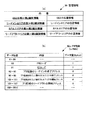
(1−3)管理情報の一具体例
次に、図4を参照して、本発明の管理情報の一具体例、及び、当該管理情報に係るエンボス情報(Embossed Information)の具体例について説明する。特に、このエンボス情報は、ディスク製造メーカーが情報記録媒体に、エンボスピットの形成によって、或いは、レーザ光によるプリ記録によって、予め記録することが好ましい。ここに、図4は、本発明の管理情報の一具体例を示したテーブル(図4(a))、本発明の管理情報に係るエンボス情報のデータ構造の具体例を示したテーブル(図4(b))、及び、本発明の第1識別情報に係るEIコード(Embossed Information Code)の具体例を示したテーブル(図4(c))である。(1-3) Specific Example of Management Information Next, with reference to FIG. 4, a specific example of the management information of the present invention and a specific example of embossed information related to the management information will be described. . In particular, this emboss information is preferably recorded in advance on the information recording medium by the disk manufacturer by forming emboss pits or by pre-recording with a laser beam. FIG. 4 is a table showing a specific example of the management information of the present invention (FIG. 4A), and a table showing a specific example of the data structure of emboss information related to the management information of the present invention (FIG. 4). (B)) and a table (FIG. 4C) showing a specific example of an EI code (Embossed Information Code) according to the first identification information of the present invention.
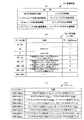
図4(a)に示されるように、本発明の管理情報50は、(i)本発明の所定の記録エリアの一具体例であるコントロールデータゾーンにおいてエンボスピットが形成されているか否かを識別する第1識別情報、(ii)本発明の所定の記録エリアの他の具体例であるリードインエリアにおいてエンボスピットが形成されているか否かを識別する第1識別情報、(iii)本発明の所定の記録エリアの他の具体例であるミドルエリアにおいてエンボスピットが形成されているか否かを識別する第1識別情報、及び(iv)本発明の所定の記録エリアの他の具体例であるリードアウトエリアにおいてエンボスピットが形成されているか否かを識別する第1識別情報を含むようにしてもよい。尚、管理情報50は、コントロールデータゾーンCDZ(以下、適宜「CDZ」と称す)や、例えば物理フォーマット情報ゾーン(RW-Physical format information zone)において、エンボス情報50aを記録するための一のフィールドを設け、例えばディスク製造メーカーがエンボス情報50aをエンボスピットの形成によって、或いは、レーザ光によるプリ記録によって、予め記録するようにしてもよい。この場合、初期状態の光ディスクに対して、情報記録再生装置は、最初に、例えばCDZの一のフィールドに記録されたエンボス情報50aをレコーディングマネージメントエリアRMA(以下、適宜「RMA」と称す)に記録し、その後、例えばファイナライズのための緩衝状態にさせることを専ら目的とするダミーデータ(パディングデータ)等の緩衝用データがレーザ光によってプリ記録されたプリ記録エリアが更新されたり、追加されたりした場合は、RMAのエンボス情報50aを更新して、最新の情報として利用するようにしてもよい。特に、ディスク製造メーカーがダミーデータを記録した場合の管理情報を初期エンボス情報(Initial Embossed Information)と称してもよい。加えて、本発明の管理情報50は、(i)当該光ディスク100に対して、記録動作を行なった情報記録再生装置の識別番号情報、所謂、ドライブID情報(ドライブ識別情報)、(ii)ドライブIDによって指定された情報記録再生装置による較正処理の結果、検出された最適記録パワーの数値情報、(iii)未記録状態、例えばインクリメンタル記録方式等の記録方式、及び追記不可能であるファイナライズ処理が済んだ状態等を示すディスク状態情報を記録するためのフィールドを保持するように構成してもよい。
As shown in FIG. 4A, the management information 50 of the present invention identifies (i) whether or not embossed pits are formed in the control data zone which is one specific example of the predetermined recording area of the present invention. (Ii) first identification information for identifying whether or not an embossed pit is formed in a lead-in area which is another specific example of the predetermined recording area of the present invention, (iii) First identification information for identifying whether embossed pits are formed in the middle area, which is another specific example of the predetermined recording area, and (iv) Lead, which is another specific example of the predetermined recording area of the present invention You may make it include the 1st identification information which identifies whether the emboss pit is formed in the out area. The management information 50 includes one field for recording the emboss information 50a in a control data zone CDZ (hereinafter referred to as “CDZ” as appropriate), for example, a physical format information zone (RW-Physical format information zone). For example, the disk manufacturer may pre-record the emboss information 50a by forming emboss pits or by pre-recording with laser light. In this case, with respect to the optical disk in the initial state, the information recording / reproducing apparatus first records, for example, the emboss information 50a recorded in one field of the CDZ in a recording management area RMA (hereinafter referred to as “RMA” as appropriate). After that, for example, a pre-recording area in which buffer data such as dummy data (padding data) exclusively intended to be put into a buffer state for finalization was pre-recorded by laser light was updated or added. In this case, the RMA emboss information 50a may be updated and used as the latest information. In particular, the management information when the disc manufacturer records the dummy data may be referred to as initial embossed information. In addition, the management information 50 of the present invention includes (i) identification number information of an information recording / reproducing apparatus that has performed a recording operation on the
具体的には、図4(b)に示されるように、管理情報50の一具体例であるエンボス情報(Embossed Information)50aは、例えばバイト単位で割り付けられた0から2047の番号で指定可能であるデータ位置の、例えば40番目に、本発明の第1識別情報の一具体例であるEIコード(Embossed Information Code)51aを含むようにしてもよい。このEIコード51aは、データ量が1バイト(Byte)であるようにしてもよい。より詳細には、図4(c)に示されるように、EIコード51aは、(i)例えばCDZにおいてエンボスピットが形成されているか否かを示す所定のビットパターンと、(ii)例えばリードインエリアにおいてエンボスピットが形成されているか否かを示す所定のビットパターンと、(iii)例えばミドルエリアにおいてエンボスピットが形成されているか否かを示す所定のビットパターンと、(iv)例えばリードアウトエリアにおいてエンボスピットが形成されているか否かを示す所定のビットパターンとが組み合わされることによって示されてもよい。
Specifically, as shown in FIG. 4B, embossed information 50a, which is a specific example of the management information 50, can be specified by a number from 0 to 2047 assigned in units of bytes, for example. An EI code (Embossed Information Code) 51a, which is a specific example of the first identification information of the present invention, may be included, for example, at the 40th position of a certain data position. The
具体的には、EIコード51aのうち右から1番目のビットが、「0」である場合、CDZにおいてエンボスピットが形成されていると意味するようにしてもよい。他方、EIコード51aのうち右から1番目のビットが、「1」である場合、CDZにおいてエンボスピットが形成されていないと意味するようにしてもよい。概ね同様にして、EIコード51aのうち右から2番目のビットが、「0」である場合、リードインエリアにおいてエンボスピットが形成されていないと意味するようにしてもよい。他方、EIコード51aのうち右から2番目のビットが、「1」である場合、リードインエリアにおいてエンボスピットが形成されていると意味するようにしてもよい。更に、概ね同様にして、EIコード51aのうち右から3番目のビットが、「0」である場合、ミドルエリアにおいてエンボスピットが形成されていないと意味するようにしてもよい。他方、EIコード51aのうち右から3番目のビットが、「1」である場合、ミドルエリアにおいてエンボスピットが形成されていると意味するようにしてもよい。更に、概ね同様にして、EIコード51aのうち右から4番目のビットが、「0」である場合、リードアウトエリアにおいてエンボスピットが形成されていないと意味するようにしてもよい。他方、EIコード51aのうち右から4番目のビットが、「1」である場合、リードアウトエリアにおいてエンボスピットが形成されていると意味するようにしてもよい。尚、右から5番目のビットから8番目のビットまでは予備のビットとしてもよい。また、各種のビットパターンによって、本発明の第1識別情報を実現することができるのは言うまでもない。加えて、記録クロックの生成処理を切り替えにおける効果、及び、アンリーダブルエンボスピットが形成されたエリアにおける効果については、後述される「(3)本実施例の作用効果の検討」において説明する。
Specifically, when the first bit from the right in the
(1−3−1)管理情報の他の具体例−その1−
次に、図5を参照して、本発明の管理情報の他の具体例、及び、当該管理情報に係るPR情報(Pre-recorded Information)の具体例について説明する。特に、このPR情報は、情報記録再生装置が情報記録媒体において追記又は書き換え可能で記録することが好ましい。ここに、図5は、本発明の管理情報の他の具体例を示したテーブル(図5(a))、本発明の管理情報に係るPR情報のデータ構造の具体例を示したテーブル(図5(b))、及び、本発明の第2識別情報に係るPRIコード(Pre-recorded Information Code)の具体例を示したテーブル(図5(c))である。(1-3-1) Another specific example of management information-1-
Next, another specific example of the management information of the present invention and a specific example of PR information (Pre-recorded Information) related to the management information will be described with reference to FIG. In particular, it is preferable that this PR information is recorded by an information recording / reproducing apparatus so that it can be additionally written or rewritten on an information recording medium. FIG. 5 is a table showing another specific example of the management information of the present invention (FIG. 5A), and a table showing a specific example of the data structure of PR information related to the management information of the present invention (FIG. 5). 5 (b)) and a table (FIG. 5 (c)) showing a specific example of a PRI code (Pre-recorded Information Code) related to the second identification information of the present invention.
図5(a)に示されるように、本発明の管理情報50は、(i−1)本発明の所定の記録エリアの一具体例であるコントロールデータゾーンにおいてレーザ光によるプリ記録が行われているか否かを識別する第2識別情報、(ii−1)本発明の所定の記録エリアの他の具体例であるリードインエリアにおいてレーザ光によるプリ記録が行われているか否かを識別する第2識別情報、(iii−1)本発明の所定の記録エリアの他の具体例であるミドルエリアにおいてレーザ光によるプリ記録が行われているか否かを識別する第2識別情報、及び(iv−1)本発明の所定の記録エリアの他の具体例であるリードアウトエリアにおいてレーザ光によるプリ記録が行われているか否かを識別する第2識別情報を含むようにしてもよい。加えて、本発明の管理情報50は、(i−2)コントロールデータゾーンの記録されている位置を特定可能な位置情報、(ii−2)リードインエリアの記録されている位置を特定可能な位置情報、(iii−2)ミドルエリアの記録されている位置を特定可能な位置情報、及び(iv−2)リードアウトエリアの記録されている位置を特定可能な位置情報を含むようにしてもよい。尚、本発明の管理情報50の一具体例であるPR情報50bは、コントロールデータゾーンCDZや、例えば物理フォーマット情報ゾーン(RW-Physical format information zone)において、PR情報50bを記録するための一のフィールドを設け、例えばディスク製造メーカーがPR情報50bをエンボスピットの形成によって、或いは、レーザ光によるプリ記録によって、予め記録するようにしてもよい。この場合、前述したように、初期状態の光ディスクに対して、情報記録再生装置は、最初に、例えばCDZの一のフィールドに記録されたPR情報50bをRMAに記録し、その後、例えばファイナライズのための緩衝状態にさせることを専ら目的とするダミーデータ(パディングデータ)等の緩衝用データがレーザ光によってプリ記録されたプリ記録エリアが更新されたり、追加されたりした場合は、RMAのPR情報50bを更新して、最新の情報として利用するようにしてもよい。或いは、PR情報50bは、例えばRMAに直接的に記録可能であるようにしてもよい。更に、或いは、PR情報50bは、例えばレコーディングマネージメントデータRMD(以下、適宜「RMD」と称す)に含まれ、このRMDを介して間接的に記録可能であるようにしてもよい。 As shown in FIG. 5 (a), the management information 50 of the present invention includes (i-1) pre-recording by laser light in a control data zone which is a specific example of a predetermined recording area of the present invention. Second identification information for identifying whether or not pre-recording by laser light is performed in a lead-in area which is another specific example of the predetermined recording area of the present invention. 2 identification information, (iii-1) second identification information for identifying whether or not pre-recording by laser light is performed in a middle area which is another specific example of the predetermined recording area of the present invention, and (iv- 1) You may make it include the 2nd identification information which identifies whether the pre-recording by a laser beam is performed in the lead-out area which is another specific example of the predetermined recording area of this invention. In addition, the management information 50 of the present invention can specify (i-2) position information capable of specifying the recorded position of the control data zone, and (ii-2) specify the recorded position of the lead-in area. Position information, (iii-2) position information that can specify the recorded position of the middle area, and (iv-2) position information that can specify the recorded position of the lead-out area may be included. Note that the PR information 50b, which is a specific example of the management information 50 of the present invention, is one for recording the PR information 50b in the control data zone CDZ or, for example, a physical format information zone (RW-Physical format information zone). For example, a disc manufacturer may record the PR information 50b in advance by forming embossed pits or by pre-recording with laser light. In this case, as described above, with respect to the optical disc in the initial state, the information recording / reproducing apparatus first records the PR information 50b recorded in, for example, one field of the CDZ in the RMA, and then, for example, for finalization. If the pre-recording area in which buffer data such as dummy data (padding data) exclusively intended for the buffer state is pre-recorded by the laser beam is updated or added, the RMA PR information 50b May be used as the latest information. Alternatively, the PR information 50b may be recorded directly on the RMA, for example. Further alternatively, the PR information 50b may be included in, for example, recording management data RMD (hereinafter referred to as “RMD” as appropriate) and indirectly recordable via this RMD.
具体的には、図5(b)に示されるように、管理情報50の他の具体例であるPR情報(Pre-recorded Information)50bは、例えばバイト単位で割り付けられた0から2047の番号で指定可能であるデータ位置の、例えば90番目に、本発明の第2識別情報の具体例であるPRIコード(Pre-recorded Information Code)51bを含むようにしてもよい。このPRIコード51bは、データ量が1バイト(Byte)であるようにしてもよい。概ね同様にして、PR情報50bは、例えば92番目から95番目に、本発明の位置情報の具体例であるレーザ光によってプリ記録されたリードインエリアの終了端を示すアドレス情報を含むようにしてもよい。また、PR情報50bは、例えば96番目から99番目に、本発明の位置情報の具体例であるレーザ光によってプリ記録されたL0層のミドルエリアの終了端を示すアドレス情報を含むようにしてもよい。また、PR情報50bは、例えば100番目から103番目に、本発明の位置情報の具体例であるレーザ光によってプリ記録されたL1層のミドルエリアの開始端を示すアドレス情報を含むようにしてもよい。また、PR情報50bは、例えば104番目から107番目に、本発明の位置情報の具体例であるレーザ光によってプリ記録されたリードアウトエリアの開始端を示すアドレス情報を含むようにしてもよい。これら4つのアドレス情報は、データ量が4バイト(Byte)であるようにしてもよい。
Specifically, as shown in FIG. 5 (b), PR information (Pre-recorded Information) 50b, which is another specific example of the management information 50, is a number from 0 to 2047 assigned in units of bytes, for example. A PRI code (Pre-recorded Information Code) 51b, which is a specific example of the second identification information of the present invention, may be included at, for example, the 90th data position that can be specified. The
より詳細には、図5(c)に示されるように、PRIコード51bは、(i)例えばCDZにおいてレーザ光によるプリ記録が行われているか否かを示す所定のビットパターンと、(ii)例えばリードインエリアにおいてレーザ光によるプリ記録が行われているか否かを示す所定のビットパターンと、(iii)例えばミドルエリアにおいてレーザ光によるプリ記録が行われているか否かを示す所定のビットパターンと、(iv)例えばリードアウトエリアにおいてレーザ光によるプリ記録が行われているか否かを示す所定のビットパターンとが組み合わされることによって示されてもよい。
More specifically, as shown in FIG. 5 (c), the
具体的には、PRIコード51bのうち右から1番目のビットが、「0」である場合、CDZにおいてレーザ光によるプリ記録が行われていると意味するようにしてもよい。他方、PRIコード51bのうち右から1番目のビットが、「1」である場合、CDZにおいてレーザ光によるプリ記録が行われていないと意味するようにしてもよい。概ね同様にして、PRIコード51bのうち右から2番目のビットが、「0」である場合、リードインエリアにおいてレーザ光によるプリ記録が行われていないと意味するようにしてもよい。他方、PRIコード51bのうち右から2番目のビットが、「1」である場合、リードインエリアにおいてレーザ光によるプリ記録が行われていると意味するようにしてもよい。更に、概ね同様にして、PRIコード51bのうち右から3番目のビットが、「0」である場合、ミドルエリアにおいてレーザ光によるプリ記録が行われていないと意味するようにしてもよい。他方、PRIコード51bのうち右から3番目のビットが、「1」である場合、ミドルエリアにおいてレーザ光によるプリ記録が行われていると意味するようにしてもよい。更に、概ね同様にして、PRIコード51bのうち右から4番目のビットが、「0」である場合、リードアウトエリアにおいてレーザ光によるプリ記録が行われていないと意味するようにしてもよい。他方、PRIコード51bのうち右から4番目のビットが、「1」である場合、リードアウトエリアにおいてレーザ光によるプリ記録が行われていると意味するようにしてもよい。尚、右から5番目のビットから8番目のビットまでは予備のビットとしてもよい。また、各種のビットパターンによって、本発明の第2識別情報を実現することができるのは言うまでもない。
Specifically, when the first bit from the right in the
この結果、後述される情報記録再生装置は、前述した管理情報の一具体例であるエンボス情報50aと、PR情報50bとの両方の情報を把握することで、ファイナライズ処理の際に、緩衝用データを記録する領域を迅速且つ的確に把握(特定)することが可能となる。尚、記録クロックの生成処理を切り替えにおける効果、及び、アンリーダブルエンボスピットが形成されたエリアにおける効果については、後述される「(3)本実施例の作用効果の検討」において説明する。 As a result, the information recording / reproducing apparatus described later grasps both the emboss information 50a, which is one specific example of the management information described above, and the PR information 50b. It is possible to quickly and accurately grasp (specify) the area for recording. The effect of switching the recording clock generation process and the effect in the area where the unreadable embossed pits are formed will be described later in “(3) Examination of effects of the present embodiment”.
(1−3−2)管理情報の他の具体例−その2−
次に、図6を参照して、本発明の管理情報の他の具体例、及び、当該管理情報に係るPR情報(Pre-recorded Information)の具体例について説明する。特に、このPR情報は、情報記録再生装置が情報記録媒体において追記又は書き換え可能で記録することが好ましい。ここに、図6は、本発明の管理情報の他の具体例を示したテーブル(図6(a))、及び、本発明の管理情報に係るPR情報のデータ構造の具体例を示したテーブル(図6(b))である。尚、前述の「(1−3−1)管理情報の他の具体例−その1−」におけるPR情報50bと同様の構成及び性質については、説明を省略する。(1-3-2) Another specific example of management information—Part 2-
Next, another specific example of the management information of the present invention and a specific example of PR information (Pre-recorded Information) related to the management information will be described with reference to FIG. In particular, it is preferable that this PR information is recorded by an information recording / reproducing apparatus so that it can be additionally written or rewritten on an information recording medium. FIG. 6 is a table showing another specific example of the management information of the present invention (FIG. 6A), and a table showing a specific example of the data structure of the PR information related to the management information of the present invention. (FIG. 6B). Note that the description of the configuration and properties similar to those of the PR information 50b in “(1-3-1) Other specific example of management information—No. 1” described above will be omitted.
図6(a)に示されるように、本発明の管理情報50は、(i−1)本発明の所定の記録エリアの一具体例であるコントロールデータゾーンにおいてエンボスピットが形成されているか否かを識別する第1識別情報、(ii−1)本発明の所定の記録エリアの他の具体例であるリードインエリアにおいてエンボスピットが形成されているか否かを識別する第1識別情報、(iii−1)本発明の所定の記録エリアの他の具体例であるミドルエリアにおいてエンボスピットが形成されているか否かを識別する第1識別情報、及び(iv−1)本発明の所定の記録エリアの他の具体例であるリードアウトエリアにおいてエンボスピットが形成されているか否かを識別する第1識別情報を含むようにしてもよい。加えて、本発明の管理情報50は、(i−2)コントロールデータゾーンにおいてレーザ光によるプリ記録が行われているか否かを識別する第2識別情報、(ii−2)リードインエリアにおいてレーザ光によるプリ記録が行われているか否かを識別する第2識別情報、(iii−2)ミドルエリアにおいてレーザ光によるプリ記録が行われているか否かを識別する第2識別情報、及び(iv−2)リードアウトエリアにおいてレーザ光によるプリ記録が行われているか否かを識別する第2識別情報を含むようにしてもよい。更に、加えて、本発明の管理情報50は、(i−3)コントロールデータゾーンの記録されている位置を特定可能な位置情報、(ii−3)リードインエリアの記録されている位置を特定可能な位置情報、(iii−3)ミドルエリアの記録されている位置を特定可能な位置情報、及び(iv−3)リードアウトエリアの記録されている位置を特定可能な位置情報を含むようにしてもよい。 As shown in FIG. 6 (a), the management information 50 of the present invention includes (i-1) whether or not embossed pits are formed in a control data zone which is a specific example of a predetermined recording area of the present invention. (Ii-1) first identification information for identifying whether embossed pits are formed in a lead-in area which is another specific example of the predetermined recording area of the present invention, (iii) -1) first identification information for identifying whether or not an embossed pit is formed in a middle area which is another specific example of the predetermined recording area of the present invention, and (iv-1) a predetermined recording area of the present invention The first identification information for identifying whether or not the embossed pit is formed in the lead-out area which is another specific example may be included. In addition, the management information 50 of the present invention includes (i-2) second identification information for identifying whether or not pre-recording by laser light is performed in the control data zone, and (ii-2) laser in the lead-in area. Second identification information for identifying whether or not pre-recording with light is performed, (iii-2) second identification information for identifying whether or not pre-recording with laser light is performed in the middle area, and (iv) -2) Second identification information for identifying whether pre-recording by laser light is performed in the lead-out area may be included. In addition, the management information 50 of the present invention includes (i-3) position information capable of specifying the recorded position of the control data zone, and (ii-3) specifying the recorded position of the lead-in area. Possible position information, (iii-3) position information capable of specifying the recorded position of the middle area, and (iv-3) position information capable of specifying the recorded position of the lead-out area. Good.
具体的には、図6(b)に示されるように、管理情報50の他の具体例であるPR情報(Pre-recorded Information)50cは、例えばバイト単位で割り付けられた0から2047の番号で指定可能であるデータ位置の、例えば91番目に、前述の図4において説明した、本発明の第1識別情報の一具体例であるEIコード(Embossed Information Code)51aを含むようにしてもよい。このEIコード51aの詳細については、前述の図4(c)における説明と同様であるので、省略する。
Specifically, as shown in FIG. 6 (b), PR information (Pre-recorded Information) 50c, which is another specific example of the management information 50, is a number from 0 to 2047 assigned in units of bytes, for example. The EI code (Embossed Information Code) 51a, which is a specific example of the first identification information of the present invention described in FIG. 4 described above, may be included in the data position that can be specified, for example, 91st. Details of the
この結果、後述される情報記録再生装置は、EIコード51aを含むPR情報50cだけを取得し、把握することで、ファイナライズ処理の際に、リーダブルエンボスピットが形成されたエリア、及び、レーザ光によるプリ記録が行われたエリアを識別しつつ、緩衝用データを記録する領域を迅速且つ的確に把握(特定)することが可能となる。尚、記録クロックの生成処理を切り替えにおける効果、及び、アンリーダブルエンボスピットが形成されたエリアにおける効果については、後述される「(3)本実施例の作用効果の検討」において説明する。
As a result, the information recording / reproducing apparatus, which will be described later, acquires and grasps only the PR information 50c including the
(1−3−3)管理情報の他の具体例−その3−
次に、図7を参照して、本発明の管理情報の他の具体例、及び、当該管理情報に係るエンボス情報(Embossed Information)の具体例について説明する。特に、このエンボス情報は、ディスク製造メーカーが情報記録媒体に、エンボスピットの形成によって、或いは、レーザ光によるプリ記録によって、予め記録することが好ましい。ここに、図7は、本発明の管理情報の他の具体例を示したテーブル(図7(a))、及び、本発明の管理情報に係るエンボス情報のデータ構造の具体例を示したテーブル(図7(b))である。尚、前述の「(1−3)管理情報の一具体例」におけるエンボス情報50aと同様の構成及び性質については、説明を省略する。(1-3-3) Another specific example of management information-Part 3-
Next, another specific example of the management information of the present invention and a specific example of embossed information related to the management information will be described with reference to FIG. In particular, this emboss information is preferably recorded in advance on the information recording medium by the disk manufacturer by forming emboss pits or by pre-recording with a laser beam. FIG. 7 is a table showing another specific example of the management information of the present invention (FIG. 7A) and a table showing a specific example of the data structure of emboss information related to the management information of the present invention. (FIG. 7B). Note that the description of the configuration and properties similar to those of the emboss information 50a in “(1-3) One specific example of management information” described above will be omitted.
図7(a)に示されるように、本発明の管理情報50は、(i−1)本発明の所定の記録エリアの一具体例であるコントロールデータゾーンにおいてエンボスピットが形成されているか否かを識別する第1識別情報、(ii−1)本発明の所定の記録エリアの他の具体例であるリードインエリアにおいてエンボスピットが形成されているか否かを識別する第1識別情報、(iii−1)本発明の所定の記録エリアの他の具体例であるミドルエリアにおいてエンボスピットが形成されているか否かを識別する第1識別情報、及び(iv−1)本発明の所定の記録エリアの他の具体例であるリードアウトエリアにおいてエンボスピットが形成されているか否かを識別する第1識別情報を含むようにしてもよい。加えて、(i−2)コントロールデータゾーンにおいてレーザ光によるプリ記録が行われているか否かを識別する第2識別情報、(ii−2)リードインエリアにおいてレーザ光によるプリ記録が行われているか否かを識別する第2識別情報、(iii−2)ミドルエリアにおいてレーザ光によるプリ記録が行われているか否かを識別する第2識別情報、及び(iv−2)リードアウトエリアにおいてレーザ光によるプリ記録が行われているか否かを識別する第2識別情報を含むようにしてもよい。 As shown in FIG. 7A, the management information 50 of the present invention includes (i-1) whether or not embossed pits are formed in a control data zone which is a specific example of a predetermined recording area of the present invention. (Ii-1) first identification information for identifying whether embossed pits are formed in a lead-in area which is another specific example of the predetermined recording area of the present invention, (iii) -1) first identification information for identifying whether or not an embossed pit is formed in a middle area which is another specific example of the predetermined recording area of the present invention, and (iv-1) a predetermined recording area of the present invention The first identification information for identifying whether or not the embossed pit is formed in the lead-out area which is another specific example may be included. In addition, (i-2) second identification information for identifying whether or not pre-recording by laser light is performed in the control data zone, and (ii-2) pre-recording by laser light is performed in the lead-in area. Second identification information for identifying whether or not, (iii-2) second identification information for identifying whether or not pre-recording by laser light is performed in the middle area, and (iv-2) a laser in the lead-out area You may make it include the 2nd identification information which identifies whether the pre-recording by light is performed.
具体的には、図7(b)に示されるように、管理情報50の一具体例であるエンボス情報(Embossed Information)50dは、例えばバイト単位で割り付けられた0から2047の番号で指定可能であるデータ位置の、例えば40番目に、本発明の第1識別情報の一具体例であるEIコード(Embossed Information Code)51aを含むようにしてもよい。加えて、例えば43番目に、本発明の第2識別情報の具体例であるPRIコード(Pre-recorded Information Code)51bを含むようにしてもよい。このEIコード51a及びPRIコード51bの詳細については、前述の図4(c)及び図5(c)における説明と同様であるので、省略する。
Specifically, as shown in FIG. 7B, embossed information 50d, which is a specific example of the management information 50, can be specified by, for example,
この結果、ディスク製造メーカーはリーダブルエンボスピットに加えて、レーザ光によるプリ記録によっても、例えばリードインエリア等の緩衝用エリアを予め形成することが可能となる。従って、後述される情報記録再生装置は、エンボス情報50dだけを取得し、把握することで、ファイナライズ処理の際に、リーダブルエンボスピットが形成されたエリア、及び、レーザ光によるプリ記録が行われたエリアを識別しつつ、緩衝用データを記録する領域を迅速且つ的確に把握(特定)することが可能となる。尚、記録クロックの生成処理を切り替えにおける効果、及び、アンリーダブルエンボスピットが形成されたエリアにおける効果については、後述される「(3)本実施例の作用効果の検討」において説明する。 As a result, in addition to the readable emboss pit, the disk manufacturer can preliminarily form a buffer area such as a lead-in area by pre-recording with a laser beam. Therefore, the information recording / reproducing apparatus to be described later acquires and grasps only the emboss information 50d, so that the area where the readable emboss pits are formed and the pre-recording by the laser beam are performed in the finalizing process. While identifying the area, it is possible to quickly and accurately grasp (specify) the area in which the buffer data is recorded. The effect of switching the recording clock generation process and the effect in the area where the unreadable embossed pits are formed will be described later in “(3) Examination of effects of the present embodiment”.
(1−3−4)管理情報の他の具体例−その4−
次に、図15を参照して、本発明の管理情報の他の具体例、及び、当該管理情報に係るPR情報(Pre-recorded Information)の具体例について説明する。特に、このPR情報は、情報記録再生装置が情報記録媒体において追記又は書き換え可能で記録することが好ましい。ここに、図15は、本発明の管理情報の他の具体例を示したテーブル(図15(a))、本発明の管理情報に係るPR情報のデータ構造の具体例を示したテーブル(図15(b))、及び、本発明の第3識別情報に係るPRIコード(Pre-recorded Information Code)の具体例を示したテーブル(図15(c))である。(1-3-4) Another specific example of management information-part 4-
Next, with reference to FIG. 15, another specific example of management information of the present invention and a specific example of PR information (Pre-recorded Information) related to the management information will be described. In particular, it is preferable that the PR information is recorded in an information recording medium so that the information recording / reproducing apparatus can additionally write or rewrite the PR information. FIG. 15 is a table (FIG. 15A) showing another specific example of the management information of the present invention, and a table (FIG. 15) showing a specific example of the data structure of the PR information related to the management information of the present invention. 15 (b)) and a table (FIG. 15 (c)) showing a specific example of a PRI code (Pre-recorded Information Code) related to the third identification information of the present invention.
図15(a)に示されるように、本発明の管理情報50は、(i−1)本発明の所定の記録エリアの一具体例であるコントロールデータゾーンにおいて(ia)エンボスピットが形成されている、又は(ib)レーザ光によるプリ記録が行われているうち、少なくともいずれか一方であるか否かを識別する第3識別情報を含むようにしてもよい。加えて、(ii−1)本発明の所定の記録エリアの他の具体例であるリードインエリアにおいて(iia)エンボスピットが形成されている、又は(iib)レーザ光によるプリ記録が行われているうち、少なくともいずれか一方であるか否かを識別する第3識別情報を含むようにしてもよい。加えて、(iii−1)本発明の所定の記録エリアの他の具体例であるミドルエリアにおいて(iiia)エンボスピットが形成されている、又は(iiib)レーザ光によるプリ記録が行われているうち、少なくともいずれか一方であるか否かを識別する第3識別情報を含むようにしてもよい。加えて(iv−1)本発明の所定の記録エリアの他の具体例であるリードアウトエリアにおいて(iva)エンボスピットが形成されている、又は(ivb)レーザ光によるプリ記録が行われているうち、少なくともいずれか一方であるか否かを識別する第3識別情報を含むようにしてもよい。更に、加えて、本発明の管理情報50は、(i−2)コントロールデータゾーンの記録されている位置を特定可能な位置情報、(ii−2)リードインエリアの記録されている位置を特定可能な位置情報、(iii−2)ミドルエリアの記録されている位置を特定可能な位置情報、並びに(iv−2)リードアウトエリアの記録されている位置を特定可能な位置情報を含むようにしてもよい。尚、本発明の管理情報50の一具体例であるPR情報50eは、コントロールデータゾーンCDZや、例えば物理フォーマット情報ゾーン(RW-Physical format information zone)において、PR情報50eを記録するための一のフィールドを設け、例えばディスク製造メーカーがPR情報50eをエンボスピットの形成によって、或いは、レーザ光によるプリ記録によって、予め記録するようにしてもよい。この場合、前述したように、初期状態の光ディスクに対して、情報記録再生装置は、最初に、例えばCDZの一のフィールドに記録されたPR情報50eをRMAに記録し、その後、例えばファイナライズのための緩衝状態にさせることを専ら目的とするダミーデータ(パディングデータ)等の緩衝用データがレーザ光によってプリ記録されたプリ記録エリアが更新されたり、追加されたりした場合は、RMAのPR情報50eを更新して、最新の情報として利用するようにしてもよい。或いは、PR情報50eは、例えばRMAに直接的に記録可能であるようにしてもよい。更に、或いは、PR情報50eは、例えばレコーディングマネージメントデータRMD(以下、適宜「RMD」と称す)に含まれ、このRMDを介して間接的に記録可能であるようにしてもよい。 As shown in FIG. 15A, the management information 50 according to the present invention includes (i-1) embossed pits formed in a control data zone which is a specific example of a predetermined recording area according to the present invention. Or (ib) third identification information for identifying whether or not pre-recording by laser light is being performed may be included. In addition, (ii-1) an embossed pit is formed in a lead-in area which is another specific example of the predetermined recording area of the present invention, or (iib) pre-recording by laser light is performed. In addition, third identification information for identifying whether at least one of them may be included. In addition, (iii-1) Embossed pits are formed in a middle area which is another specific example of the predetermined recording area of the present invention, or (iiib) pre-recording by laser light is performed. Third identification information for identifying whether at least one of them may be included. In addition, (iv-1) Embossed pits are formed in the lead-out area which is another specific example of the predetermined recording area of the present invention, or (ivb) pre-recording by laser light is performed. Third identification information for identifying whether at least one of them may be included. In addition, the management information 50 of the present invention includes (i-2) position information capable of specifying the recorded position of the control data zone, and (ii-2) specifying the recorded position of the lead-in area. Possible position information, (iii-2) position information capable of specifying the recorded position of the middle area, and (iv-2) position information capable of specifying the recorded position of the lead-out area. Good. The PR information 50e, which is a specific example of the management information 50 according to the present invention, is a record for recording the PR information 50e in the control data zone CDZ or, for example, a physical format information zone (RW-Physical format information zone). For example, a disc manufacturer may record the PR information 50e in advance by forming embossed pits or by pre-recording with laser light. In this case, as described above, with respect to the optical disk in the initial state, the information recording / reproducing apparatus first records the PR information 50e recorded in, for example, one field of the CDZ in the RMA, and then, for example, for finalization. If the pre-recording area in which buffer data such as dummy data (padding data) exclusively intended for the buffer state is pre-recorded by the laser beam is updated or added, the RMA PR information 50e May be used as the latest information. Alternatively, the PR information 50e may be directly recordable in the RMA, for example. Alternatively, the PR information 50e may be included in, for example, recording management data RMD (hereinafter referred to as “RMD” as appropriate) and indirectly recordable via the RMD.
具体的には、図15(b)に示されるように、管理情報50の他の具体例であるPR情報(Pre-recorded Information)50eは、例えばバイト単位で割り付けられた0から2047の番号で指定可能であるデータ位置の、例えば90番目に、本発明の第3識別情報の具体例であるPRIコード(Pre-recorded Information Code)51eを含むようにしてもよい。このPRIコード51eは、データ量が1バイト(Byte)であるようにしてもよい。概ね同様にして、PR情報50eは、例えば92番目から95番目に、本発明の位置情報の具体例である(i)エンボスピットが形成されている、又は(ii)レーザ光によってプリ記録されたリードインエリアの終了端を示すアドレス情報を含むようにしてもよい。また、PR情報50eは、例えば96番目から99番目に、本発明の位置情報の具体例である(i)エンボスピットが形成されている、又は(ii)レーザ光によってプリ記録されたL0層のミドルエリアの終了端を示すアドレス情報を含むようにしてもよい。また、PR情報50eは、例えば100番目から103番目に、本発明の位置情報の具体例である(i)エンボスピットが形成されている、又は(ii)レーザ光によってプリ記録されたL1層のミドルエリアの開始端を示すアドレス情報を含むようにしてもよい。また、PR情報50eは、例えば104番目から107番目に、本発明の位置情報の具体例である(i)エンボスピットが形成されている、又は(ii)レーザ光によってプリ記録されたリードアウトエリアの開始端を示すアドレス情報を含むようにしてもよい。これら4つのアドレス情報は、データ量が4バイト(Byte)であるようにしてもよい。
Specifically, as shown in FIG. 15 (b), PR information (Pre-recorded Information) 50e, which is another specific example of the management information 50, is a number from 0 to 2047 assigned in units of bytes, for example. A PRI code (Pre-recorded Information Code) 51e, which is a specific example of the third identification information of the present invention, may be included in, for example, the 90th data position that can be specified. The
より詳細には、図15(c)に示されるように、PRIコード51eは、(i)例えばCDZにおいて(ia)エンボスピットが形成されている、又は(ib)レーザ光によるプリ記録が行われているか否かを示す所定のビットパターンと、(ii)例えばリードインエリアにおいて(iia)エンボスピットが形成されている、又は(iib)レーザ光によるプリ記録が行われているか否かを示す所定のビットパターンと、(iii)例えばミドルエリアにおいて(iiia)エンボスピットが形成されている、又は(iiib)レーザ光によるプリ記録が行われているか否かを示す所定のビットパターンと、(iv)例えばリードアウトエリアにおいて(iva)エンボスピットが形成されている、又は(ivb)レーザ光によるプリ記録が行われているか否かを示す所定のビットパターンとが組み合わされることによって示されてもよい。
More specifically, as shown in FIG. 15C, the
具体的には、PRIコード51eのうち右から1番目のビットが、「0」である場合、CDZにおいて(ia)エンボスピットが形成されている、又は(ib)レーザ光によるプリ記録が行われていると意味するようにしてもよい。他方、PRIコード51eのうち右から1番目のビットが、「1」である場合、CDZにおいて(ia)エンボスピットが形成されていない、且つ(ib)レーザ光によるプリ記録が行われていないと意味するようにしてもよい。詳細には、PRIコード51eのうち右から1番目のビットは、(ia)エンボスピットが形成されているか否かを示すフラグ等の情報と、(ib)レーザ光によるプリ記録が行われているか否かを示すフラグ等の情報と、の論理和であるようにしてもよい。より詳細には、PRIコード51eのうち右から1番目のビットが「1」になる場合は、次の3つの場合であるようにしてもよい。即ち、1つ目の場合は、CDZの全体がエンボスピットだけにより形成されている場合である。2つ目の場合は、CDZの全体がレーザ光によるプリ記録だけにより行われている場合である。3つ目の場合は、CDZにおいてエンボスピットが形成されていると共に、レーザ光によるプリ記録が行われている場合である。尚、3つ目の場合は、本実施例では、省略可能であるようにしてもよい。
Specifically, when the first bit from the right in the
概ね同様にして、PRIコード51eのうち右から2番目のビットが、「0」である場合、リードインエリアにおいて(iia)エンボスピットが形成されていない、且つ(iib)レーザ光によるプリ記録が行われていないと意味するようにしてもよい。特に、この場合、後述される情報記録再生装置は、リードインエリアの少なくとも一部において、エンボスピットが形成されていないと共に、プリ記録が行われていないので、ファイナライズ処理の際には、例えばダミーデータ等の緩衝用データの記録を行う必要があると判別することが可能である。他方、PRIコード51eのうち右から2番目のビットが、「1」である場合、リードインエリアにおいて(iia)エンボスピットが形成されている、又は(iib)レーザ光によるプリ記録が行われていると意味するようにしてもよい。更に、概ね同様にして、PRIコード51eのうち右から3番目のビットが、「0」である場合、ミドルエリアにおいて(iiia)エンボスピットが形成されていない、且つ(iiib)レーザ光によるプリ記録が行われていないと意味するようにしてもよい。他方、PRIコード51eのうち右から3番目のビットが、「1」である場合、ミドルエリアにおいて(iiia)エンボスピットが形成されている、又は(iiib)レーザ光によるプリ記録が行われていると意味するようにしてもよい。更に、概ね同様にして、PRIコード51eのうち右から4番目のビットが、「0」である場合、リードアウトエリアにおいて(iva)エンボスピットが形成されていない、且つ(ivb)レーザ光によるプリ記録が行われていないと意味するようにしてもよい。他方、PRIコード51eのうち右から4番目のビットが、「1」である場合、リードアウトエリアにおいて(iva)エンボスピットが形成されている、又は(ivb)レーザ光によるプリ記録が行われていると意味するようにしてもよい。尚、右から5番目のビットから8番目のビットまでは予備のビットとしてもよい。また、各種のビットパターンによって、本発明の第3識別情報を実現することができるのは言うまでもない。
In substantially the same manner, when the second bit from the right of the
特に、PRIコード51eにおいて、少なくとも一部のビットパターンを固定にして使用しても良い。例えば、CDZは常に、エンボスピットを形成するようにし、PRIコード51eのうち右から一番目のビットを常に「0」に固定して使用してもよい。
In particular, in the
この結果、後述される情報記録再生装置は、上述した管理情報の他の具体例であるPR情報50eの情報を把握することで、ファイナライズ処理の際に、緩衝用データを記録する領域を迅速且つ的確に把握(特定)することが可能となる。尚、記録クロックの生成処理を切り替えにおける効果、及び、アンリーダブルエンボスピットが形成されたエリアにおける効果については、後述される「(3)本実施例の作用効果の検討」において説明する。 As a result, the information recording / reproducing apparatus to be described later grasps the information of the PR information 50e, which is another specific example of the management information described above, so that the area for recording the buffering data can be quickly and accurately used in the finalizing process. It becomes possible to grasp (identify) accurately. The effect of switching the recording clock generation process and the effect in the area where the unreadable embossed pits are formed will be described later in “(3) Examination of effects of the present embodiment”.
(2)情報記録装置の実施例
次に、図8から図11を参照して、本発明の情報記録装置の実施例の構成及び動作について詳細に説明する。特に、本実施例は、本発明に係る情報記録装置を光ディスク用の情報記録再生装置に適用した例である。(2) Embodiment of Information Recording Apparatus Next, the configuration and operation of an embodiment of the information recording apparatus of the present invention will be described in detail with reference to FIGS. In particular, the present embodiment is an example in which the information recording apparatus according to the present invention is applied to an information recording / reproducing apparatus for an optical disc.
(2−1)基本構成
先ず、図8を参照して、本発明の情報記録装置に係る実施例における情報記録再生装置300及び、ホストコンピュータ400の基本構成について説明する。ここに、図8は、本発明の情報記録装置の実施例に係る情報記録再生装置、及び、ホストコンピュータの基本構成を示したブロック図である。尚、情報記録再生装置300は、光ディスク100に記録データを記録する機能と、光ディスク100に記録された記録データを再生する機能とを備える。(2-1) Basic Configuration First, the basic configuration of the information recording / reproducing apparatus 300 and the host computer 400 in the embodiment of the information recording apparatus of the present invention will be described with reference to FIG. FIG. 8 is a block diagram showing the basic configuration of the information recording / reproducing apparatus and the host computer according to the embodiment of the information recording apparatus of the present invention. The information recording / reproducing apparatus 300 has a function of recording record data on the
図8を参照して情報記録再生装置300の内部構成を説明する。情報記録再生装置300は、ドライブ用のCPU(Central Processing Unit)305の制御下で、光ディスク100に情報を記録すると共に、光ディスク100に記録された情報を読み取る装置である。
The internal configuration of the information recording / reproducing apparatus 300 will be described with reference to FIG. The information recording / reproducing apparatus 300 is an apparatus that records information on the
情報記録再生装置300は、光ディスク100、光ピックアップ301、信号記録再生手段302、アドレス検出部303、CPU(ドライブ制御手段)305、スピンドルモータ306、メモリ307、データ入出力制御手段308、及びバス309を備えて構成されている。
The information recording / reproducing apparatus 300 includes an
また、ホストコンピュータ400は、CPU(ホスト制御手段)401、メモリ402、操作制御手段403、操作ボタン404、表示パネル405、データ入出力制御手段406、及びバス407を備えて構成される。
The host computer 400 includes a CPU (host control means) 401, a memory 402, operation control means 403,
特に、情報記録再生装置300は、例えばモデム等の通信手段を備えたホストコンピュータ400を同一筐体内に収めることにより、外部ネットワークと通信可能となるように構成してもよい。或いは、例えばi−link等の通信手段を備えたホストコンピュータ400のCPU(ホスト制御手段)401が、データ入出力制御手段308、及びバス309を介して、直接情報記録再生装置300を制御することによって、外部ネットワークと通信可能となるように構成してもよい。
In particular, the information recording / reproducing apparatus 300 may be configured to be communicable with an external network by housing the host computer 400 equipped with communication means such as a modem in the same housing. Alternatively, the CPU (host control means) 401 of the host computer 400 having communication means such as i-link controls the information recording / reproducing apparatus 300 directly via the data input / output control means 308 and the
光ピックアップ301は光ディスク100への記録再生を行うもので、半導体レーザ装置とレンズから構成される。より詳細には、光ピックアップ301は、光ディスク100に対してレーザービーム等の光ビームを、再生時には読み取り光として第1のパワーで照射し、記録時には書き込み光として第2のパワーで且つ変調させながら照射する。
The
信号記録再生手段302は、光ピックアップ301とスピンドルモータ306とを制御することで光ディスク100に対して記録又は再生を行う。より具体的には、信号記録再生手段302は、例えば、レーザダイオードドライバ(LDドライバ)及びヘッドアンプ等によって構成されている。レーザダイオードドライバは、光ピックアップ301内に設けられた図示しない半導体レーザを駆動する。ヘッドアンプは、光ピックアップ301の出力信号、即ち、光ビームの反射光を増幅し、該増幅した信号を出力する。より詳細には、信号記録再生手段302は、OPC(Optimum Power Control)処理時には、CPU305の制御下で、図示しないタイミング生成器等と共に、OPCパターンの記録及び再生処理により最適なレーザパワーの決定が行えるように、光ピックアップ301内に設けられた図示しない半導体レーザを駆動する。特に、信号記録再生手段302は、光ピックアップ301と共に、本発明に係る「記録手段」及び「再生手段」の一例を構成する。また、信号記録再生手段302は、例えばコントロールデータゾーンCDZ、あるいはレコーディングマネージメントエリアRMA0(RMA1)に記録された管理情報50を取得可能であるようにしてもよい。よって、信号記録再生手段302は、本発明に係る「取得手段」の一例を構成するようにしてもよい。
The signal recording / reproducing
アドレス検出部303は、信号記録再生手段302によって出力される、例えばプリフォーマットアドレス信号等を含む再生信号から光ディスク100におけるアドレス(アドレス情報)を検出する。
The
CPU(ドライブ制御手段)305は、バス309を介して、各種制御手段に指示を行うことで、情報記録再生装置300全体の制御を行う。尚、CPU305が動作するためのソフトウェア又はファームウェアは、メモリ307に格納されている。特に、CPU305は、本発明に係る「制御手段」の一例を構成する。
A CPU (drive control means) 305 controls the entire information recording / reproducing apparatus 300 by giving instructions to various control means via the
スピンドルモータ306は光ディスク100を回転及び停止させるもので、光ディスクへのアクセス時に動作する。より詳細には、スピンドルモータ306は、図示しないサーボユニット等によりスピンドルサーボを受けつつ所定速度で光ディスク100を回転及び停止させるように構成されている。
The spindle motor 306 rotates and stops the
メモリ307は、記録再生データのバッファ領域や、信号記録再生手段302で使用出来るデータに変換する時の中間バッファとして使用される領域など情報記録再生装置300におけるデータ処理全般及びOPC処理において使用される。また、メモリ307はこれらレコーダ機器としての動作を行うためのプログラム、即ちファームウェアが格納されるROM領域と、記録再生データの一時格納用バッファや、ファームウェアプログラム等の動作に必要な変数が格納されるRAM領域などから構成される。
The
データ入出力制御手段308は、情報記録再生装置300に対する外部からのデータ入出力を制御し、メモリ307上のデータバッファへの格納及び取り出しを行う。情報記録再生装置300と、SCSIやATAPI等のインターフェースを介して接続されている外部のホストコンピュータ400(以下、適宜ホストと称す)から発行されるドライブ制御命令は、当該データ入出力制御手段308を介してCPU305に伝達される。また、記録再生データも同様にして、当該データ入出力制御手段308を介して、ホストコンピュータ400に対して送受信される。
The data input / output control means 308 controls external data input / output with respect to the information recording / reproducing apparatus 300, and stores and retrieves data in / from the data buffer on the
ホストコンピュータ400における、CPU(ホスト制御手段)401、メモリ402、データ入出力制御手段406、及びバス407は、これらに対応される、情報記録再生装置300内の構成要素と、概ね同様である。
In the host computer 400, the CPU (host control means) 401, the memory 402, the data input / output control means 406, and the
操作制御手段403は、ホストコンピュータ400に対する動作指示受付と表示を行うもので、例えば記録又は再生といった操作ボタン404による指示をCPU401に伝える。CPU401は、操作制御手段403からの指示情報を元に、データ入出力手段406を介して、情報記録再生装置300に対して制御命令(コマンド)を送信し、情報記録再生装置300全体を制御するように構成してもよい。同様に、CPU401は、情報記録再生装置300に対して、動作状態をホストに送信するように要求するコマンドを送信することができる。これにより、記録中や再生中といった情報記録再生装置300の動作状態が把握できるためCPU401は、操作制御手段403を介して蛍光管やLCDなどの表示パネル405に情報記録再生装置300の動作状態を出力することができる。
The
以上説明した、情報記録再生装置300とホストコンピュータ400を組み合わせて使用する一具体例は、映像を記録再生するレコーダ機器等の家庭用機器である。このレコーダ機器は放送受信チューナや外部接続端子からの映像信号をディスクに記録し、テレビなど外部表示機器にディスクから再生した映像信号を出力する機器である。メモリ402に格納されたプログラムをCPU401で実行させることでレコーダ機器としての動作を行っている。また、別の具体例では、情報記録再生装置300はディスクドライブ(以下、適宜ドライブと称す)であり、ホストコンピュータ400はパーソナルコンピュータやワークステーションである。パーソナルコンピュータ等のホストコンピュータとドライブはSCSIやATAPIといったデータ入出力制御手段308(406)を介して接続されており、ホストコンピュータにインストールされているライティングソフトウェア等のアプリケーションが、ディスクドライブを制御する。
One specific example in which the information recording / reproducing apparatus 300 and the host computer 400 described above are used in combination is a household device such as a recorder device that records and reproduces video. This recorder device is a device that records a video signal from a broadcast receiving tuner or an external connection terminal on a disk and outputs a video signal reproduced from the disk to an external display device such as a television. An operation as a recorder device is performed by causing the
(2−2)動作原理
次に、図9から図11に加えて前述した図8を適宜参照して、本発明の情報記録装置の実施例に係る情報記録再生装置における動作原理について説明する。ここに、図9は、本発明の情報記録装置の実施例に係る情報記録再生装置によるEIコード(Embossed Information Code)51aの取得処理を示したフローチャートである。図10は、本発明の情報記録装置の実施例に係る情報記録再生装置によるプリ記録処理を示したフローチャートである。図11は、本発明の情報記録装置の実施例に係る情報記録再生装置によるPRIコード51bの更新処理を示したフローチャートである。(2-2) Operation Principle Next, the operation principle of the information recording / reproducing apparatus according to the embodiment of the information recording apparatus of the present invention will be described with reference to FIG. 8 described above in addition to FIGS. FIG. 9 is a flowchart showing an acquisition process of an EI code (Embossed Information Code) 51a by the information recording / reproducing apparatus according to the embodiment of the information recording apparatus of the present invention. FIG. 10 is a flowchart showing the pre-recording process by the information recording / reproducing apparatus according to the embodiment of the information recording apparatus of the present invention. FIG. 11 is a flowchart showing the update process of the
(2−2−1)EIコード(Embossed Information Code)の取得処理
図9に示されるように、EIコード51aの取得処理においては、先ず、CPU(ドライブ制御手段)305の制御下で、光ディスクが挿入されたか否かが判定される(ステップS101)。ここで、光ディスクが挿入された場合(ステップS101:Yes)、CPU305の制御下で、CDZに予め記録されているEIコード51aが読み取られる(ステップS102)。(2-2-1) EI Code (Embossed Information Code) Acquisition Process As shown in FIG. 9, in the acquisition process of the
次に、CPU305の制御下で、読み取られたEIコード51aに基づいて、(i)リーダブルエンボスピットから記録クロックを生成するように、記録クロックの生成処理を切り替える位置と、通常の通り、ランドプリピットから記録クロックを生成するように、記録クロックの生成処理を切り替える位置とに関する情報が取得される。加えて、例えば再生エラーが発生しやすい、アンリーダブルエンボスピットが形成されたエリアの位置に関する情報が取得される(ステップS103)。
Next, under the control of the
次に、CPU305の制御下で、RMAに記録されている、最新のRMD(Recording Management Data)が再生され、PRIコード51bが読み取られる(ステップS104)。
Next, under the control of the
次に、CPU305の制御下で、再生された最新のRMDにおいて、EIコード51aが記録されているか否かが判定される(ステップS105)。ここで、再生されたRMDにおいて、EIコード51aが記録されていない場合(ステップS105:No)、CPU305の制御下で、CDZから読み取られたEIコード51aを含むRMDを、最新のRMDとして、RMAに記録する(ステップS106)。具体的には、前述の図6中のPR情報50c中のデータ位置の91番目にEIコード51aをコピーするようにしてもよい。
Next, under the control of the
次に、CPU305の制御下で、最新のRMDに含まれるEIコード51a、及び、PRIコード51bから、ファイナライズ処理の際に緩衝用データを記録する必要のあるエリア(例えばリードインエリア、リードアウトエリア、及びミドルエリア等)の位置が把握(特定)される(ステップS107)。
Next, under the control of the
他方、ステップS105の判定の結果、再生されたRMDにおいて、EIコード51aが記録されている場合(ステップS105:Yes)、前述したステップS106は省略される。また、他方、ステップS101の判定の結果、光ディスクが挿入されない場合(ステップS101:No)、再度、光ディスクが挿入されたか否かが判定される(ステップS101)。
On the other hand, when the
(2−2−2)プリ記録処理
図10に示されるように、レーザ光によるプリ記録を行う処理(以下、適宜「プリ記録処理」と称す)においては、先ず、CPU305の制御下で、ホストコンピュータから、プリ記録処理を開始させる、例えばプリライトコマンドが発呼されたか否かが判定される(ステップS201)。ここで、プリ記録処理を開始させるプリライトコマンドが発呼された場合(ステップS201:Yes)、CPU305の制御下で、最新のRMDに含まれるPRIコード51bから、ファイナライズ処理の際に緩衝用データを記録する必要のあるエリア(領域)のプリ記録を開始するアドレスに関する情報が取得される(ステップS202)。他方、ステップS201の判定の結果、プリ記録処理を開始させるプリライトコマンドが発呼されない場合(ステップS201:No)、再び、コマンドの発呼を待つ。(2-2-2) Pre-Recording Process As shown in FIG. 10, in the process of performing pre-recording with laser light (hereinafter referred to as “pre-recording process” as appropriate), first, under the control of the
次に、CPU305の制御下で、CDZに予め記録されているEIコード51aが読み取られ、読み取られたEIコード51aに基づいて、(i)リーダブルエンボスピットから記録クロックを生成するように、記録クロックの生成処理を切り替える位置と、通常の通り、ランドプリピットから記録クロックを生成するように、記録クロックの生成処理を切り替える位置とに関する情報が取得される。加えて、(ii)例えば再生エラーが発生しやすい、アンリーダブルエンボスピットが形成されたエリアの位置に関する情報が取得される(ステップS203)。仮に、当該情報記録媒体が、他の情報記録再生装置に挿入された場合、最新のRMDを読み取るだけではリーダブルエンボスピットで形成されたものであるか、情報記録再生装置によって、あとから緩衝用データが記録されたものであるかを判断することはできない。これに対して、本発明では、ディスク製造メーカーが予め記録したCDZから読み取られたEIコード51aに基づいて、(i)リーダブルエンボスピットから記録クロックを生成するように、記録クロックの生成処理を切り替える位置と、通常の通り、ランドプリピットから記録クロックを生成するように、記録クロックの生成処理を切り替える位置とに関する情報が取得される。加えて、(ii)例えば再生エラーが発生しやすい、アンリーダブルエンボスピットが形成されたエリアの位置に関する情報が取得される。
Next, under the control of the
次に、CPU305の制御下で、例えば緩衝用データのプリ記録が実行される(ステップS204)。 Next, for example, pre-recording of buffer data is executed under the control of the CPU 305 (step S204).
次に、CPU305の制御下で、PRIコード51bの更新を行うか否かが判定される(ステップS205)。ここで、PRIコード51bの更新を行う場合(ステップS205:Yes)、CPU305の制御下で、PRIコード51bの更新処理が行われる(ステップS206)。また、他方、PRIコード51bの更新を行わない場合(ステップS205:No)、そのまま終了する。
Next, it is determined whether or not to update the
(2−2−3)PR情報の更新処理
図11に示されるように、PR情報50b(50c)の更新処理においては、先ず、CPU305の制御下で、例えばホストコンピュータから、PR情報50b(50c)を更新させるコマンドが発呼されたか否かが判定される(ステップS301)。特に、CPU305が、所定のタイミングや所定のイベントに対応して、自らこの判定を行うようにしてもよい。(2-2-3) PR Information Update Process As shown in FIG. 11, in the PR information 50b (50c) update process, first, under the control of the
次に、CPU305の制御下で、プリ記録が行われたエリア(記録領域)の開始アドレス、及び終了アドレスが取得される(ステップS302)。
Next, under the control of the
次に、最新のRMDに含まれるPR情報50b(50c)に有されるPRコードが更新されると共に、新しくプリ記録が行われたエリア(記録領域)の位置を示す開始アドレス、及び終了アドレスが追加され、最新のRMDとして、RMAに記録される(ステップS303)。 Next, the PR code included in the PR information 50b (50c) included in the latest RMD is updated, and the start address and end address indicating the position of the newly pre-recorded area (recording area) are set. It is added and recorded in the RMA as the latest RMD (step S303).
この結果、情報記録再生装置は、更新された最新のRMDに含まれるEIコード51a、及び、PRIコード51bから、ファイナライズ処理の際に緩衝用データを記録する必要のあるエリア(例えばリードインエリア、リードアウトエリア、及びミドルエリア等)の位置が把握(特定)される。
As a result, the information recording / reproducing apparatus uses the
尚、上述したPRIコードやPR情報50b(50c)の更新処理は、情報記録再生装置における、例えばメモリ等の記憶手段の上で行われて、例えば光ディスクの排出時に、RMAに記録されるようにしてもよい。或いは、情報記録再生装置によって、更新が行われる都度、光ディスクのRMA上において、直接的に、PRIコードやPR情報50b(50c)の更新のための記録が行われるようにしてもよい。 The above-described updating process of the PRI code and the PR information 50b (50c) is performed on a storage unit such as a memory in the information recording / reproducing apparatus, and is recorded on the RMA when the optical disk is ejected, for example. May be. Alternatively, recording for updating the PRI code or the PR information 50b (50c) may be performed directly on the RMA of the optical disk every time the information recording / reproducing apparatus performs the update.
(3)本実施例の作用効果の検討
次に、図12及び図13を参照して本実施例の作用効果について検討を加える。ここに、図12は、本発明の情報記録媒体の実施例に係る光ディスクの内周側及び外周側においてリーダブルエンボスピットが形成されたエリアを図式的に示した模式図である。図13は、本発明の情報記録媒体の実施例に係る光ディスクの内周側及び外周側においてリーダブルエンボスピットが形成されたエリアと、アンリーダブルエンボスピットが形成されたエリアとを図式的に示した模式図である。(3) Examination of operational effects of the present embodiment Next, the operational effects of the present embodiment will be examined with reference to FIGS. 12 and 13. FIG. 12 is a schematic diagram schematically showing areas where readable embossed pits are formed on the inner and outer peripheral sides of the optical disc in the embodiment of the information recording medium of the present invention. FIG. 13 schematically shows an area in which readable embossed pits are formed and an area in which unreadable embossed pits are formed on the inner and outer peripheral sides of an optical disc according to an embodiment of the information recording medium of the present invention. It is a schematic diagram.
一般的に、例えば、DVD−RW DL(Dual Layer)では、図12及び図13のグレー部分に示されるエリア(領域)において、リーダブルエンボスピットを形成することが可能である。このリーダブルエンボスピットが形成されたエリアにおいては、リーダブルエンボスピットとランドプリピット(LPP:Land Pre-Pit)との干渉による影響を低減するために、リーダブルエンボスピットが形成されたエリアにおいては、ランドプリピットは重畳されない。従って、例えばリードインエリア、リードアウトエリア、又はミドルエリア等の緩衝用エリアにおけるリーダブルエンボスピットが形成されたエリアの一部に隣接するエリア(Groove area)において記録を開始する場合、次のような技術的な問題点が生じてしまう。即ち、隣接するリーダブルエンボスエリアにおいてはランドプリピットが形成されていないため、その直後の記録可能エリアにおいて記録を開始する時点ではランドプリピットから記録クロックを生成することは技術的に困難となってしまう。 In general, for example, in DVD-RW DL (Dual Layer), readable embossed pits can be formed in an area (region) shown in a gray portion in FIGS. 12 and 13. In the area where the readable embossed pits are formed, in order to reduce the influence of interference between the readable embossed pits and the Land Pre-Pit (LPP), Pre-pits are not superimposed. Accordingly, for example, when recording is started in an area (Groove area) adjacent to a part of an area where a readable emboss pit is formed in a buffer area such as a lead-in area, a lead-out area, or a middle area, Technical problems will arise. That is, since no land pre-pit is formed in the adjacent readable emboss area, it is technically difficult to generate a recording clock from the land pre-pit when recording is started in the immediately recordable area. End up.
そのため、次のような2つの手法が一般的に提案されている。即ち(i)例えばリードインエリア等の緩衝用エリアに形成されたリーダブルエンボスピットから記録クロックを生成する手法が提案されている。或いは(ii)現行のDVD−RWのように、例えばリードインエリア等の緩衝用エリアに形成されたリーダブルエンボスピットに隣接するエリアにおいては、ランドプリピットを重畳することが可能なアンリーダブルエンボスピット(Unreadable Emboss Pit)が形成されたエリアを設ける手法についても提案されている。ここに、本実施例に係る「アンリーダブルエンボスピット」とは、情報記録再生装置によってトラッキング制御を行わしめることを目的とし、アドレス等の情報を保持しない、リーダブルエンボスピットと比較して凹凸の小さいピットのことである。 Therefore, the following two methods are generally proposed. That is, (i) a method for generating a recording clock from a readable emboss pit formed in a buffer area such as a lead-in area has been proposed. Or (ii) Unreadable embossed pits in which land prepits can be superimposed in an area adjacent to readable embossed pits formed in a buffer area such as a lead-in area as in the current DVD-RW A method of providing an area where (Unreadable Emboss Pit) is formed has also been proposed. Here, the “unreadable embossed pit” according to the present embodiment is intended to perform tracking control by an information recording / reproducing apparatus, and has less unevenness than a readable embossed pit that does not hold information such as an address. It is a pit.
これに対して、本実施例に係る光ディスクにおいては、本発明の所定の記録エリアにおいてエンボスピットが形成されているか否かを識別する第1識別情報を含む管理情報が記録可能であるので、次のような例えば4つの効果を享受することが可能である。 On the other hand, in the optical disc according to the present embodiment, management information including first identification information for identifying whether or not the embossed pit is formed in the predetermined recording area of the present invention can be recorded. For example, it is possible to enjoy four effects.
1つ目の効果としては、前述した(i)の手法を採用した場合、先ず、リーダブルエンボスピットが形成されているか否かを識別する第1識別情報(前述したEIコード51a)が、情報記録再生装置によって取得される。次に、当該情報記録再生装置は、リーダブルエンボスピットが形成されたエリアの位置等を把握(特定)できるので、リーダブルエンボスエリアの直後に位置するエリアに記録する場合に適切な記録クロック生成処理を行うことができる。即ち、リーダブルエンボスエリアの直後に記録する場合は、その少し前のリーダブルエンボスエリアにおいて、ランドプリピットの代わりに、リーダブルエンボスピットから記録クロックを生成するように、記録クロックの生成処理を切り替える(図12中の白抜きの矢印を参照)。具体的には、図12(a)中のL0層におけるBuffer zone 0の終了端、及びCDZの終了端、並びに、L1層におけるリードアウトエリアの途中、図12(b)中のL0層におけるミドルエリアの途中、並びに、L1層におけるミドルエリアの終了端まで、リーダブルエンボスピットから記録クロックを生成するように、記録クロックの生成処理を行う。
As a first effect, when the method (i) described above is employed, first identification information (
その後、記録が実施されるリーダブルエンボスピットが形成されていないエリアに入ったら記録を開始し、それと同時にリーダブルエンボスピットの代わりに、通常の通り、ランドプリピットから記録クロックを生成するように、記録クロックの生成処理を切り替える(図12中の黒塗りの矢印を参照)。具体的には、図12(a)中のL0層におけるRW-Physical format information zoneの開始端、及びExtra Border Zoneの開始端、並びに、L1層におけるリードアウトエリアの途中、図12(b)中のL0層におけるミドルエリアの途中、並びに、L1層におけるミドルエリアの終了端から、通常の通り、ランドプリピットから記録クロックを生成するように、記録クロックの生成処理を切り替える。このような記録クロックの生成処理を行うことにより、リーダブルエンボスエリアの直後に位置するエリアに適切な記録を行うことが可能となる。 After that, when entering the area where the readable emboss pit is not formed, recording is started, and at the same time, instead of the readable emboss pit, the recording clock is generated from the land pre-pit as usual. The clock generation process is switched (see the black arrow in FIG. 12). Specifically, the start end of the RW-Physical format information zone in the L0 layer in FIG. 12A, the start end of the Extra Border Zone, and the middle of the lead-out area in the L1 layer, in FIG. 12B The recording clock generation processing is switched so that the recording clock is generated from the land pre-pits as usual from the middle of the middle area in the L0 layer and from the end of the middle area in the L1 layer. By performing such a recording clock generation process, appropriate recording can be performed in an area located immediately after the readable emboss area.
2つ目の効果としては、例えば、前述した(ii)の手法を採用した場合、先ず、リーダブルエンボスピットが形成されているか否かを識別する第1識別情報(EIコード)が、例えば情報記録再生装置によって取得される。次に、情報記録再生装置は、リーダブルエンボスピットが形成されたエリアの位置と、このエリアに隣接するアンリーダブルエンボスピットが形成されたエリアの位置とを把握(特定)できる(図13中の黒塗り部分を参照)。従って、仮にアンリーダブルエンボスピットが形成されたエリアにおいて、例えば再生エラーが発生しアドレス情報を取得できなかった場合でも、情報記録再生装置は、このエリアにおいて発生する再生エラーを予見して無視する等のフェイルセーフ処理を含む記録再生動作を実現することが可能となる。 As the second effect, for example, when the method (ii) described above is employed, first identification information (EI code) for identifying whether or not a readable emboss pit is formed is, for example, information recording Obtained by the playback device. Next, the information recording / reproducing apparatus can grasp (specify) the position of the area where the readable embossed pit is formed and the position of the area where the unreadable embossed pit adjacent to this area is formed (black in FIG. 13). See fill). Therefore, even if, for example, a reproduction error occurs and the address information cannot be acquired in the area where the unreadable emboss pit is formed, the information recording / reproducing apparatus foresees and ignores the reproduction error occurring in this area. The recording / reproducing operation including the fail-safe process can be realized.
3つ目の効果としては、例えば情報記録再生装置は、リーダブルエンボスピットが形成されているエリアを検索するためのRFサーチや、LPPサーチを行う必要が殆ど又は完全にないので、それらのサーチに要する時間を、記録再生処理から省略することが可能となる。仮に、例えばDVD−R DL等の情報記録媒体においては、エンボスピットが形成されているか否かを識別する第1識別情報を含む管理情報は存在しない。よって、従来技術においては、記録クロックの生成処理を切り替える位置や、記録情報を読み取ることができないと共に、アンリーダブルエンボスピットが形成されている読取不能エリアの位置を把握(特定)するためには、情報記録再生装置自身が、当該情報記録媒体において、例えばRF信号を取得できるエリアを検索するRFサーチ、及び、例えばLPP信号を取得できるエリアを検索するLPPサーチを行う必要が生じてしまい、それらのサーチにための時間が余分に発生してしまう。 As a third effect, for example, the information recording / reproducing apparatus has little or no need to perform an RF search or an LPP search for searching an area where a readable emboss pit is formed. The time required can be omitted from the recording / reproducing process. For example, in an information recording medium such as a DVD-R DL, there is no management information including first identification information for identifying whether or not an embossed pit is formed. Therefore, in the prior art, in order to grasp (specify) the position where the recording clock generation processing is switched and the position where the unreadable embossed pits are formed and the recorded information cannot be read, The information recording / reproducing apparatus itself needs to perform, for example, an RF search for searching an area where the RF signal can be acquired in the information recording medium and an LPP search for searching an area where the LPP signal can be acquired. Extra time is required for the search.
これに対して、本発明では、本発明の所定の記録エリアにおいてエンボスピットが形成されているか否かを識別する第1識別情報を含む管理情報が、例えば情報記録再生装置によって取得可能であるので、RFサーチや、LPPサーチを行う必要が殆ど又は完全にないので、それらのサーチに要する時間を、記録再生処理から省略することが可能となる。 On the other hand, in the present invention, management information including first identification information for identifying whether or not embossed pits are formed in the predetermined recording area of the present invention can be acquired by, for example, an information recording / reproducing apparatus. Since there is little or no need to perform an RF search or an LPP search, the time required for these searches can be omitted from the recording / playback process.
4つ目の効果としては、例えば情報記録再生装置は、前述した管理情報に含まれる第2識別情報(PRIコード51b)に加えて、本発明の第1識別情報(EIコード51a)を把握することで、ファイナライズ処理の際に、リーダブルエンボスピットが形成されたエリア、及び、レーザ光によるプリ記録が行われたエリアを識別しつつ、緩衝用データを記録する領域を迅速且つ的確に把握(特定)することが可能となる。具体的には、第1識別情報に基づいて、ディスク製造メーカーによってエンボスピットが形成され緩衝用データの記録する必要のない領域を把握(特定)することが可能である。加えて、第2識別情報に基づいて、情報記録再生装置によって例えばプリ記録処理によって緩衝用データが既に記録され、ファイナライズ処理の際に緩衝用データの記録する必要のない領域を把握(特定)することが可能である。以上の結果、当該情報記録媒体のファイナライズ処理に掛かる時間の大幅な短縮や、より効率的な短縮を実現させることが可能となり、ユーザは、ファイナライズ処理において、より大きな快適性を体感することが可能となる。
As a fourth effect, for example, the information recording / reproducing apparatus grasps the first identification information (
(4)情報記録媒体の第2実施例
次に、図14を参照して、本発明の情報記録媒体の第2実施例に係る単層型光ディスクの詳細構成について説明する。より具体的には、図14を参照して、単層型光ディスクのデータ構造、該光ディスクの記録領域におけるECCブロックを構成する物理的セクタ番号等のアドレス、並びに、該光ディスクの記録又は再生手順について説明する。ここに、図14は、本発明の情報記録媒体の第2実施例に係る単層型光ディスクのデータ構造及び該光ディスクの記録領域におけるECCブロックを構成する物理的セクタ番号等のアドレス、並びに、該光ディスクにおける記録又は再生方法を示した概念的グラフである。尚、図14中の縦軸は、例えば16進数で表現されたセクタ番号等のアドレスを示し、横軸は、光ディスクの半径方向の相対的な位置を示す。(4) Second Example of Information Recording Medium Next, with reference to FIG. 14, a detailed configuration of a single-layer optical disk according to a second example of the information recording medium of the present invention will be described. More specifically, referring to FIG. 14, the data structure of a single-layer optical disc, the addresses such as physical sector numbers constituting the ECC block in the recording area of the optical disc, and the recording or reproducing procedure of the optical disc explain. FIG. 14 shows the data structure of the single-layer optical disc according to the second embodiment of the information recording medium of the present invention, the addresses such as physical sector numbers constituting the ECC block in the recording area of the optical disc, 3 is a conceptual graph showing a recording or reproducing method on an optical disc. Note that the vertical axis in FIG. 14 indicates an address such as a sector number expressed in hexadecimal, for example, and the horizontal axis indicates a relative position in the radial direction of the optical disc.
図14に示されるように、本発明の情報記録媒体の実施例に係る単層型光ディスク100aは、図示しない透明基板に積層された記録層を備えて構成されている。記録層には、内周側から外周側にかけて、インナーディスクテスティングエリアIDTA、レコーディングマネージメントエリアRMA、リードインエリア101、データエリア102、リードアウトエリア103、アウターディスクテスティングエリアODTAが設けられている。尚、IDTA、及びODTA内の矢印は、パワーキャリブレーションのために記録領域が消費されていく方向を示している。
As shown in FIG. 14, the single-layer
上述した実施例では、情報記録媒体の一具体例として、例えばブルーレイ、赤色LD光、又は赤外光等のレーザ光によって記録又は再生が可能な、2層型、単層型の光ディスクについて説明した。加えて、本発明は、例えば、3層以上の記録層を備える多層型(マルチプルレイヤ型)の光ディスクにも適用可能である。更に、他の高密度記録或いは高転送レート対応の各種の情報記録媒体にも適用可能である。 In the above-described embodiments, as a specific example of the information recording medium, a two-layer type or single-layer type optical disc that can be recorded or reproduced by laser light such as Blu-ray, red LD light, or infrared light has been described. . In addition, the present invention can be applied to, for example, a multilayer type (multiple layer type) optical disc having three or more recording layers. Furthermore, the present invention can be applied to various information recording media compatible with other high-density recording or high transfer rate.
また、上述した実施例では、情報記録装置、及び情報再生装置の一具体例として、例えば2層型や単層型の光ディスクに対応した情報記録再生装置について説明した。加えて、本発明は、例えば、3層以上の記録層を備える多層型(マルチプルレイヤ型)の光ディスクに対応した情報記録再生装置にも適用可能である。更に、他の高密度記録或いは高転送レート対応の各種の情報記録媒体に対応した情報記録再生装置にも適用可能である。 In the above-described embodiments, as an example of the information recording apparatus and the information reproducing apparatus, the information recording / reproducing apparatus corresponding to, for example, a two-layer type or a single layer type optical disk has been described. In addition, the present invention can also be applied to an information recording / reproducing apparatus compatible with, for example, a multilayer (multiple layer type) optical disc having three or more recording layers. Furthermore, the present invention can also be applied to an information recording / reproducing apparatus compatible with various information recording media compatible with other high-density recording or high transfer rate.
本発明は、上述した実施例に限られるものではなく、請求の範囲及び明細書全体から読み取れる発明の要旨或いは思想に反しない範囲で適宜変更可能であり、そのような変更を伴う、情報記録媒体、情報記録装置及び方法、情報再生装置及び方法、コンピュータプログラムもまた本発明の技術的範囲に含まれるものである。 The present invention is not limited to the above-described embodiments, and can be changed as appropriate without departing from the scope or spirit of the invention that can be read from the claims and the entire specification. An information recording apparatus and method, an information reproducing apparatus and method, and a computer program are also included in the technical scope of the present invention.
本発明に係る情報記録媒体、情報記録装置及び方法、情報再生装置及び方法、並びに、コンピュータプログラムは、例えばDVD(Digital Versatile Disc)、BD(Blu-ray Disc)、CD(Compact Disc)等のレーザ光を照射することによって記録及び再生が可能な光ディスクに利用可能であり、また当該情報記録媒体の記録装置及び再生装置に利用可能である。また、例えば民生用或いは業務用の各種コンピュータ機器に搭載される又は各種コンピュータ機器に接続可能な情報記録装置及び情報再生装置等にも利用可能である。
An information recording medium, an information recording apparatus and method, an information reproducing apparatus and method, and a computer program according to the present invention include a laser such as a DVD (Digital Versatile Disc), a BD (Blu-ray Disc), and a CD (Compact Disc). The present invention can be used for an optical disc that can be recorded and reproduced by irradiating light, and can be used for a recording apparatus and a reproducing apparatus for the information recording medium. Further, for example, the present invention can be used for an information recording apparatus and an information reproducing apparatus that are mounted on or connectable to various computer equipment for consumer use or business use.
Claims (7)
前記第1記録層及び前記第2記録層における夫々の記録エリアに対して、当該記録エリアの少なくとも一部において、エンボスピットが形成されている又はレーザ光によるプリ記録が行われているうち少なくともいずれか一方であるか否かを識別する当該記録エリア毎の識別情報、並びに、エンボスが形成された又はプリ記録された前記リードインエリア内の終了端を示すアドレス情報、エンボスが形成された又はプリ記録された前記第1記録層上の前記ミドルエリア内の終了端を示すアドレス情報、エンボスが形成された又はプリ記録された前記第2記録層上の前記ミドルエリア内の開始端を示すアドレス情報、及びエンボスが形成された又はプリ記録された前記リードアウトエリア内の開始端を示すアドレス情報を含む前記管理情報を記録可能な管理エリアを備えることを特徴とする情報記録媒体。 A first recording layer having a recording area of a lead-in area, a data area, and a middle area in order from the inner circumference side to an outer circumference side, and a recording area of a lead-out area, a data area, and a middle area in order from the inner circumference side to the outer circumference side. A second recording layer ,
For each recording area in the first recording layer and the second recording layer, at least one of embossed pits is formed in at least a part of the recording area or pre-recording by laser light is performed. Identification information for identifying each recording area, address information indicating the end in the lead-in area where embossing is formed or pre-recorded, embossing is formed or pre-recorded Address information indicating the end edge in the middle area on the recorded first recording layer, address information indicating the start edge in the middle area on the second recording layer on which the emboss is formed or pre-recorded , and serial the management information including address information indicating a start end of the lead-out area where embossing is that has been or is pre-recorded form Information recording medium, characterized in that it comprises a possible management area.
前記管理エリアから前記管理情報を取得する取得手段と、
前記記録データを記録する記録手段と、
取得された前記管理情報に基づいて、前記記録データを記録するように前記記録手段を制御する制御手段と
を備えることを特徴とする情報記録装置。An information recording apparatus for recording record data on the information recording medium according to claim 1,
Obtaining means for obtaining the management information from the management area;
Recording means for recording the recording data;
An information recording apparatus comprising: a control unit that controls the recording unit to record the recording data based on the acquired management information.
前記管理エリアから前記管理情報を取得する取得手段と、
前記記録データを再生する再生手段と、
取得された前記管理情報に基づいて、前記記録データを再生するように前記再生手段を制御する制御手段と
を備えることを特徴とする情報再生装置。An information reproducing apparatus for reproducing recorded data from the information recording medium according to claim 1,
Obtaining means for obtaining the management information from the management area;
Reproducing means for reproducing the recorded data;
An information reproducing apparatus comprising: control means for controlling the reproducing means so as to reproduce the recorded data based on the acquired management information.
前記管理エリアから前記管理情報を取得する取得工程と、
取得された前記管理情報に基づいて、前記記録データを記録するように前記記録手段を制御する制御工程と
を備えることを特徴とする情報記録方法。An information recording method in an information recording apparatus comprising recording means for recording record data on the information recording medium according to claim 1,
An acquisition step of acquiring the management information from the management area;
And a control step of controlling the recording means so as to record the recording data based on the acquired management information.
前記管理エリアから前記管理情報を取得する取得工程と、
取得された前記管理情報に基づいて、前記記録データを再生するように前記再生手段を制御する制御工程と
を備えることを特徴とする情報再生方法。An information reproducing method in an information reproducing apparatus comprising reproducing means for reproducing recorded data from the information recording medium according to claim 1,
An acquisition step of acquiring the management information from the management area;
And a control step of controlling the reproducing means so as to reproduce the recorded data based on the acquired management information.
Applications Claiming Priority (5)
| Application Number | Priority Date | Filing Date | Title |
|---|---|---|---|
| JP2005256956 | 2005-09-05 | ||
| JP2005256956 | 2005-09-05 | ||
| JP2006007983 | 2006-01-16 | ||
| JP2006007983 | 2006-01-16 | ||
| PCT/JP2006/317500 WO2007029672A1 (en) | 2005-09-05 | 2006-09-05 | Information recording medium, information recording device and method, information reproducing device and method, and computer program |
Publications (2)
| Publication Number | Publication Date |
|---|---|
| JPWO2007029672A1 JPWO2007029672A1 (en) | 2009-03-19 |
| JP4445552B2 true JP4445552B2 (en) | 2010-04-07 |
Family
ID=37835792
Family Applications (1)
| Application Number | Title | Priority Date | Filing Date |
|---|---|---|---|
| JP2007534414A Active JP4445552B2 (en) | 2005-09-05 | 2006-09-05 | Information recording medium, information recording apparatus and method, information reproducing apparatus and method, and computer program |
Country Status (5)
| Country | Link |
|---|---|
| US (1) | US7885157B2 (en) |
| JP (1) | JP4445552B2 (en) |
| CN (1) | CN101258549B (en) |
| TW (1) | TWI348154B (en) |
| WO (1) | WO2007029672A1 (en) |
Families Citing this family (1)
| Publication number | Priority date | Publication date | Assignee | Title |
|---|---|---|---|---|
| KR20070102079A (en) * | 2006-04-13 | 2007-10-18 | 삼성전자주식회사 | Prepit formed information storage medium and recording / reproducing apparatus and recording / reproducing method |
Family Cites Families (9)
| Publication number | Priority date | Publication date | Assignee | Title |
|---|---|---|---|---|
| JP3720624B2 (en) | 1999-04-26 | 2005-11-30 | 株式会社リコー | Optical disc recording / reproducing apparatus and optimum recording power value determination method for optical disc |
| JP3783909B2 (en) | 1999-05-20 | 2006-06-07 | パイオニア株式会社 | CUTTING DEVICE, INFORMATION RECORDING MEDIUM, INFORMATION RECORDING DEVICE, INFORMATION RECORDING METHOD, AND CUTTING METHOD |
| JP2001023237A (en) | 1999-07-02 | 2001-01-26 | Pioneer Electronic Corp | Optical recording medium |
| EP1199714B1 (en) * | 2000-04-03 | 2006-10-04 | Kabushiki Kaisha Toshiba | Information recording medium adaptive to copy protection and recording/reproducing apparatus |
| AU8620901A (en) | 2000-09-13 | 2002-03-26 | Matsushita Electric Industrial Co Ltd | Optical information recording medium and optical information recording method, optical information recording device |
| JP2003036643A (en) | 2001-07-24 | 2003-02-07 | Fuji Photo Film Co Ltd | Recording tape cartridge |
| WO2003036643A1 (en) | 2001-10-23 | 2003-05-01 | Fujitsu Limited | Optical disk, optical disk access device, and access method |
| JP2004134044A (en) | 2002-10-15 | 2004-04-30 | Sony Corp | Data recording medium, data recording method and information terminal device, and information service method and information service device |
| EP1702324A1 (en) * | 2004-01-05 | 2006-09-20 | Samsung Electronics Co, Ltd | Optical recording medium, apparatus for recording/reproducing data on/from optical recording medium and method of recording/reproducing data on/from optical recording medium |
-
2006
- 2006-09-05 CN CN2006800325416A patent/CN101258549B/en active Active
- 2006-09-05 US US12/065,762 patent/US7885157B2/en active Active
- 2006-09-05 TW TW095132695A patent/TWI348154B/en not_active IP Right Cessation
- 2006-09-05 JP JP2007534414A patent/JP4445552B2/en active Active
- 2006-09-05 WO PCT/JP2006/317500 patent/WO2007029672A1/en not_active Ceased
Also Published As
| Publication number | Publication date |
|---|---|
| CN101258549A (en) | 2008-09-03 |
| JPWO2007029672A1 (en) | 2009-03-19 |
| TWI348154B (en) | 2011-09-01 |
| WO2007029672A1 (en) | 2007-03-15 |
| TW200737139A (en) | 2007-10-01 |
| US20090161508A1 (en) | 2009-06-25 |
| CN101258549B (en) | 2011-02-09 |
| US7885157B2 (en) | 2011-02-08 |
Similar Documents
| Publication | Publication Date | Title |
|---|---|---|
| JP4063858B2 (en) | Information recording apparatus and method, and computer program for recording control | |
| US7933192B2 (en) | Information recording medium, information recording apparatus and method, and computer program | |
| JPWO2007091620A1 (en) | Information recording medium, information recording apparatus and method, and computer program | |
| JP4445552B2 (en) | Information recording medium, information recording apparatus and method, information reproducing apparatus and method, and computer program | |
| JP4395509B2 (en) | Information recording medium, information recording apparatus and method, and computer program | |
| JP4577698B2 (en) | Information recording medium, information recording apparatus and method, information reproducing apparatus and method, and computer program | |
| US7948843B2 (en) | Information recording medium, apparatus and method for recording information, and computer program | |
| JP4828548B2 (en) | Information recording apparatus and method | |
| JPWO2006003978A1 (en) | Information recording medium, information recording apparatus, and computer program | |
| JP2007066398A (en) | Information recorder and method, and computer program | |
| US20090040899A1 (en) | Information Recording Device and Method, Computer Program for Record Control, and Information Recording Medium | |
| JP2007115339A (en) | Information recording medium, information recording apparatus and method, information reproducing apparatus and method, and computer program | |
| US20090135707A1 (en) | Information recording device and method, computer program and information recording medium | |
| US20090296539A1 (en) | Information Recording Apparatus and Method, Computer Program | |
| US20090268593A1 (en) | Information recording medium, information recording apparatus and method, information reproducing apparatus and method, and computer program | |
| JP2007073101A (en) | Information recording medium, information recording device and method , and computer program | |
| JP2007193881A (en) | Information recording device and method, and computer program | |
| WO2007138708A1 (en) | Information recording medium, information recording device and method, information reproducing device and method, information recording/reproducing device and recording method, and computer program |
Legal Events
| Date | Code | Title | Description |
|---|---|---|---|
| A131 | Notification of reasons for refusal |
Free format text: JAPANESE INTERMEDIATE CODE: A131 Effective date: 20090721 |
|
| A521 | Request for written amendment filed |
Free format text: JAPANESE INTERMEDIATE CODE: A523 Effective date: 20090812 |
|
| TRDD | Decision of grant or rejection written | ||
| A01 | Written decision to grant a patent or to grant a registration (utility model) |
Free format text: JAPANESE INTERMEDIATE CODE: A01 Effective date: 20091222 |
|
| A01 | Written decision to grant a patent or to grant a registration (utility model) |
Free format text: JAPANESE INTERMEDIATE CODE: A01 |
|
| A61 | First payment of annual fees (during grant procedure) |
Free format text: JAPANESE INTERMEDIATE CODE: A61 Effective date: 20100115 |
|
| R150 | Certificate of patent or registration of utility model |
Ref document number: 4445552 Country of ref document: JP Free format text: JAPANESE INTERMEDIATE CODE: R150 Free format text: JAPANESE INTERMEDIATE CODE: R150 |
|
| FPAY | Renewal fee payment (event date is renewal date of database) |
Free format text: PAYMENT UNTIL: 20130122 Year of fee payment: 3 |
|
| FPAY | Renewal fee payment (event date is renewal date of database) |
Free format text: PAYMENT UNTIL: 20140122 Year of fee payment: 4 |
|
| S111 | Request for change of ownership or part of ownership |
Free format text: JAPANESE INTERMEDIATE CODE: R313113 |
|
| S531 | Written request for registration of change of domicile |
Free format text: JAPANESE INTERMEDIATE CODE: R313531 |
|
| R371 | Transfer withdrawn |
Free format text: JAPANESE INTERMEDIATE CODE: R371 |
|
| S111 | Request for change of ownership or part of ownership |
Free format text: JAPANESE INTERMEDIATE CODE: R313113 |
|
| S531 | Written request for registration of change of domicile |
Free format text: JAPANESE INTERMEDIATE CODE: R313531 |
|
| R350 | Written notification of registration of transfer |
Free format text: JAPANESE INTERMEDIATE CODE: R350 |
|
| R250 | Receipt of annual fees |
Free format text: JAPANESE INTERMEDIATE CODE: R250 |