JP4444941B2 - Porous glass base material manufacturing equipment - Google Patents
Porous glass base material manufacturing equipment Download PDFInfo
- Publication number
- JP4444941B2 JP4444941B2 JP2006316025A JP2006316025A JP4444941B2 JP 4444941 B2 JP4444941 B2 JP 4444941B2 JP 2006316025 A JP2006316025 A JP 2006316025A JP 2006316025 A JP2006316025 A JP 2006316025A JP 4444941 B2 JP4444941 B2 JP 4444941B2
- Authority
- JP
- Japan
- Prior art keywords
- air
- base material
- reaction chamber
- glass base
- porous glass
- Prior art date
- Legal status (The legal status is an assumption and is not a legal conclusion. Google has not performed a legal analysis and makes no representation as to the accuracy of the status listed.)
- Active
Links
Images


Classifications
-
- C—CHEMISTRY; METALLURGY
- C03—GLASS; MINERAL OR SLAG WOOL
- C03B—MANUFACTURE, SHAPING, OR SUPPLEMENTARY PROCESSES
- C03B37/00—Manufacture or treatment of flakes, fibres, or filaments from softened glass, minerals, or slags
- C03B37/01—Manufacture of glass fibres or filaments
- C03B37/012—Manufacture of preforms for drawing fibres or filaments
- C03B37/014—Manufacture of preforms for drawing fibres or filaments made entirely or partially by chemical means, e.g. vapour phase deposition of bulk porous glass either by outside vapour deposition [OVD], or by outside vapour phase oxidation [OVPO] or by vapour axial deposition [VAD]
- C03B37/018—Manufacture of preforms for drawing fibres or filaments made entirely or partially by chemical means, e.g. vapour phase deposition of bulk porous glass either by outside vapour deposition [OVD], or by outside vapour phase oxidation [OVPO] or by vapour axial deposition [VAD] by glass deposition on a glass substrate, e.g. by inside-, modified-, plasma-, or plasma modified- chemical vapour deposition [ICVD, MCVD, PCVD, PMCVD], i.e. by thin layer coating on the inside or outside of a glass tube or on a glass rod
-
- C—CHEMISTRY; METALLURGY
- C03—GLASS; MINERAL OR SLAG WOOL
- C03B—MANUFACTURE, SHAPING, OR SUPPLEMENTARY PROCESSES
- C03B37/00—Manufacture or treatment of flakes, fibres, or filaments from softened glass, minerals, or slags
- C03B37/01—Manufacture of glass fibres or filaments
- C03B37/012—Manufacture of preforms for drawing fibres or filaments
- C03B37/014—Manufacture of preforms for drawing fibres or filaments made entirely or partially by chemical means, e.g. vapour phase deposition of bulk porous glass either by outside vapour deposition [OVD], or by outside vapour phase oxidation [OVPO] or by vapour axial deposition [VAD]
- C03B37/01406—Deposition reactors therefor
-
- C—CHEMISTRY; METALLURGY
- C03—GLASS; MINERAL OR SLAG WOOL
- C03B—MANUFACTURE, SHAPING, OR SUPPLEMENTARY PROCESSES
- C03B19/00—Other methods of shaping glass
- C03B19/14—Other methods of shaping glass by gas- or vapour- phase reaction processes
-
- C—CHEMISTRY; METALLURGY
- C03—GLASS; MINERAL OR SLAG WOOL
- C03B—MANUFACTURE, SHAPING, OR SUPPLEMENTARY PROCESSES
- C03B37/00—Manufacture or treatment of flakes, fibres, or filaments from softened glass, minerals, or slags
- C03B37/01—Manufacture of glass fibres or filaments
- C03B37/012—Manufacture of preforms for drawing fibres or filaments
- C03B37/014—Manufacture of preforms for drawing fibres or filaments made entirely or partially by chemical means, e.g. vapour phase deposition of bulk porous glass either by outside vapour deposition [OVD], or by outside vapour phase oxidation [OVPO] or by vapour axial deposition [VAD]
- C03B37/0144—Means for after-treatment or catching of worked reactant gases
-
- C—CHEMISTRY; METALLURGY
- C03—GLASS; MINERAL OR SLAG WOOL
- C03B—MANUFACTURE, SHAPING, OR SUPPLEMENTARY PROCESSES
- C03B2207/00—Glass deposition burners
- C03B2207/42—Assembly details; Material or dimensions of burner; Manifolds or supports
Description
本発明は、大型の多孔質ガラス母材を製造する場合であっても、透明ガラス化時に気泡や異物の発生が少ない多孔質ガラス母材の製造装置に関する。 The present invention relates to an apparatus for producing a porous glass base material, which is less likely to generate bubbles and foreign matters during transparent vitrification even when producing a large porous glass base material.
光ファイバ母材の製造方法としては、VAD法は良く知られた方法である。この方法では、回転しつつ上昇するシャフトに出発部材を取り付け、反応室内に垂下し、反応室内に設置されたコア堆積用バーナとクラッド堆積用バーナにより生成したガラス微粒子を出発部材の先端に堆積させて、コア層とクラッド層からなる多孔質ガラス母材(以下、単に多孔質母材と称する)が製造される。
生成されたガラス微粒子の堆積効率は100%とはならないため、堆積されなかった未付着の余剰のガラス微粒子が製造の間を通して発生している。この余剰のガラス微粒子の大部分は、排気ガス等の他の気体とともに排気口より反応室外に排出される。
The VAD method is a well-known method for manufacturing an optical fiber preform. In this method, a starting member is attached to a rotating shaft that rises and hangs down in a reaction chamber, and glass particles generated by a core deposition burner and a cladding deposition burner installed in the reaction chamber are deposited on the tip of the starting member. Thus, a porous glass base material (hereinafter simply referred to as a porous base material) composed of a core layer and a clad layer is manufactured.
Since the deposition efficiency of the generated glass particles does not become 100%, unattached surplus glass particles that have not been deposited are generated throughout the production. Most of the excess glass fine particles are discharged out of the reaction chamber from the exhaust port together with other gases such as exhaust gas.
しかしながら、バーナで生成されてから排出されるまでの間に、その一部は反応室の天井や側壁に付着する。この反応室の内壁に付着したガラス微粒子が剥離・落下して反応室内に飛散し、製造中の多孔質母材に付着して、透明ガラス化時に光ファイバ母材に気泡や異物を生じる原因となることがあった。 However, a part of it adheres to the ceiling or side wall of the reaction chamber after it is generated by the burner and discharged. The glass particles adhering to the inner wall of the reaction chamber are peeled off, dropped, scattered into the reaction chamber, and adhered to the porous base material being manufactured, which may cause bubbles and foreign matters in the optical fiber base material during transparent vitrification. There was.
近年、製造コストの低減が要求され、光ファイバ母材の大型化が図られている。この光ファイバ母材の大型化にともなって原料投入量が増し、堆積効率が変化しなくても未付着ガラス微粒子の絶対量が増すこととなる。このため、反応室の内壁に付着したガラス微粒子が剥離・落下する頻度の上昇は避けられなかった。 In recent years, reduction in manufacturing cost has been demanded, and an increase in the size of an optical fiber preform has been achieved. As the optical fiber preform becomes larger, the amount of raw material input increases, and the absolute amount of unattached glass particles increases even if the deposition efficiency does not change. For this reason, an increase in the frequency with which the glass particles adhering to the inner wall of the reaction chamber peel and fall is inevitable.
このような問題を解決するために、反応室内に積極的に空気を導入して、反応室内の気流を整流とし、その流れに載せて余剰のガラス微粒子を反応室外に排出する方法が提案されている。
特許文献1では、バーナの両サイドに設けた給気口にフィルターを設置し、この給気口から清浄な空気を強制的に反応室内に導入することによって、整流を作り出している。
また、特許文献2は、反応室前室にブロアーの空気を供給し、反応室内に設置されたフィルターを通して反応室後室に清浄な空気を供給することにより、整流を作り出している。
In Patent Document 1, rectification is created by installing a filter at an air supply port provided on both sides of a burner and forcibly introducing clean air into the reaction chamber from the air supply port.
しかしながら、これらの方法では、バーナの近傍にフィルターが存在するために、熱によるフィルターの劣化が激しく、一部がパーティクルとなって反応室内に飛散し、透明ガラス化時に光ファイバ母材中に異物が発生するという問題がある。また、反応室内の余剰のガラス微粒子がフィルターに付着し、それが再飛散することによって気泡が発生するという問題がある。 However, in these methods, a filter is present in the vicinity of the burner, so that the filter is severely deteriorated by heat, and some of the particles become particles and scatter in the reaction chamber. There is a problem that occurs. In addition, there is a problem that bubbles are generated when excess glass fine particles in the reaction chamber adhere to the filter and re-scatter.
そこで、本発明は、VAD法により多孔質母材を製造する装置において、大型の多孔質母材を製造する場合においても、気泡や異物の発生が少ない多孔質母材の得られる製造装置を提供することを目的としている。 Therefore, the present invention provides a manufacturing apparatus for producing a porous base material with less generation of bubbles and foreign matter, even when a large porous base material is manufactured in an apparatus for manufacturing a porous base material by the VAD method. The purpose is to do.
本発明は、このような課題を解決して達成されたものであり、本発明の多孔質母材の製造装置は、ガラス用原料、可燃性ガス及び助燃性ガスをバーナに供給し、酸水素火炎中で生成するガラス微粒子を堆積させて多孔質ガラス母材を製造する装置において、フィルターを通した清浄空気が空気分配容器に供給され、該空気分配容器の複数の排出口から、反応室の壁面に設けられた複数の給気口を通って反応室内に清浄空気が供給されることを特徴としている。
なお、反応室の給気口形状に応じて形成された複数の面からなる突起状形状部が空気分配容器内に形成され、該突起状形状部にダクトから供給された清浄空気を衝突させることで清浄空気が排出口に向かって分配される。
The present invention has been accomplished by solving such problems, and the porous base material manufacturing apparatus of the present invention supplies a raw material for glass, a combustible gas and a combustible gas to a burner, and oxyhydrogen In an apparatus for producing a porous glass base material by depositing glass fine particles generated in a flame, clean air that has passed through a filter is supplied to an air distribution container, and from a plurality of outlets of the air distribution container, Clean air is supplied into the reaction chamber through a plurality of air supply ports provided on the wall surface.
In addition, a protrusion-shaped portion having a plurality of surfaces formed according to the shape of the air supply port of the reaction chamber is formed in the air distribution container, and clean air supplied from the duct is caused to collide with the protrusion-shaped portion. Clean air is distributed toward the outlet.
反応室と空気分配容器は、スライドレール及びローラーにより分離可能に構成され、空気分配容器の排出口と反応室の給気口との間に取り付けられたシールパッキンにより、反応室への空気分配容器取り付け時に密閉状態とされる。また、空気分配容器の排出口又は反応室の給気口に、抵抗付与部材を配設するのが好ましく、この抵抗付与部材をメッシュ構造とし、メッシュの粗さを選択することで、各給気口への風量を調整することができる。また、抵抗付与部材をパンチングして穿孔したパンチング構造とし、パンチングの間隔及び大きさを選択することで、各給気口への風量を調整することもできる。 The reaction chamber and the air distribution container are configured to be separable by a slide rail and a roller, and the air distribution container to the reaction chamber is provided by a seal packing attached between the discharge port of the air distribution container and the air supply port of the reaction chamber. Sealed when installed. In addition, it is preferable to provide a resistance imparting member at the discharge port of the air distribution container or the air supply port of the reaction chamber. The resistance imparting member has a mesh structure, and by selecting the mesh roughness, The air volume to the mouth can be adjusted. Moreover, it is also possible to adjust the air volume to each air supply port by selecting a punching structure by punching the resistance imparting member and selecting a punching interval and size.
本発明によれば、透明ガラス化したときに気泡や異物の発生の少ない光ファイバ母材が得られる、大型の多孔質母材の製造が可能となる。 According to the present invention, it is possible to produce a large-sized porous base material that can obtain an optical fiber base material with less generation of bubbles and foreign matters when it is made into transparent glass.
以下、本発明の形態について、その一例を挙げて具体的に説明するが、本発明は様々な態様が可能であり、これらに限定されるものではない。
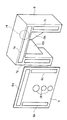
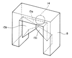
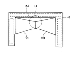
なお、図1は、本発明による製造装置の概略を示す縦断面図であり、図2は、反応室の後壁に設けられた給気口と、空気分配容器に設けられた排出口の概略を示す斜視図である。図3は、空気分配容器の内部を透視して示す概略透視図であり、図4は、内部に設置された3枚の板によって形成された突起形状部を示す概略図である。図5は、空気分配容器を、反応室からの分離を可能とする機構を示している。
Hereinafter, although an example is given and the form of this invention is concretely demonstrated, various aspects are possible for this invention, and it is not limited to these.
1 is a longitudinal sectional view showing an outline of the production apparatus according to the present invention, and FIG. 2 is an outline of an air supply port provided on the rear wall of the reaction chamber and an exhaust port provided on the air distribution container. FIG. FIG. 3 is a schematic perspective view showing the inside of the air distribution container in a transparent manner, and FIG. 4 is a schematic view showing a protrusion-shaped portion formed by three plates installed inside. FIG. 5 shows a mechanism that allows the air distribution container to be separated from the reaction chamber.
この装置は、反応室1内に多孔質母材2に向かって、バーナ3a〜3cと対向する壁側に排気口4を有し、後壁5のバーナ群の上部に給気口6aが、両サイドに給気口6b,6cがそれぞれ設けられている。反応室1の給気口6a〜6cには、図2の斜視図に示されているように、これと同じ形状の排出口7a〜7cを有する空気分配容器8が、シールパッキン9及び抵抗付与材10を介して取り付けられている。抵抗付与材10としては、例えば、テフロンシートにパンチングしたものなどが挙げられる。
This apparatus has an
空気分配容器8には、室内空気をブロアー11でフィルター12を通して清浄とした清浄空気がダクト13、ダクト用開口部14を経て供給される。空気分配容器8に供給された清浄空気流は、図2〜4に示されているように、内部に設置された3枚の板15a〜15cで形成された突起形状部に衝突し、各板に沿って上部及び両サイドへと3方向に分配される。すなわち、15aの板に当たった空気は、この板に沿って上方に導かれ7aの排出口から、反応室1の給気口6aを通って反応室1内に入り、天井に沿って流れる。15b,15cの板に当たった空気は、それぞれの板に沿って左右に分かれ、排出口7b,7c及び給気口6b,6cを経て反応室1内に入り、それぞれ反応室1の左右側壁に沿って整流となつて流れ、余剰のガラス微粒子を室外に排出する。なお、符号18はバーナ用開口部である。
The
空気分配容器8は、図5に示すように、反応室1から分離可能とし、かつローラー16によりスライドレール17に沿って進退自在とすることにより、バーナ交換、あるいはバーナの位置調整等を容易に行うことができる。
As shown in FIG. 5, the
(実施例1)
コア堆積用バーナ3aに、原料ガスとして450 ml/minのSiCl4と25 ml/minのGeCl4を供給した。クラッド堆積用バーナ3b,3cには、原料ガスとしてそれぞれ1.0
l/min、3.0 l/minのSiCl4を供給した。ガラス微粒子の堆積中、ブロアーから2 m3/minの空気を、空気分配容器8を用いて反応室1内に供給した。
この条件でガラス微粒子の堆積を36時間続けたところ、余剰のガラス微粒子は、反応室内を流れる整流に乗って室外に排出され、反応室壁面へのススの付着は見られなかった。なお、ブロアーの前に設置されたフィルター12は、反応室1から離れているために、その温度は室温であり、熱によって損傷を受けることはなかった。また、反応室1の余剰のガラス微粒子がフィルター12に付着することもなかった。
このようにして製造された多孔質母材2から、気泡も異物も無い光ファイバ用ガラス母材が得られた。
Example 1
450 ml / min SiCl 4 and 25 ml / min GeCl 4 were supplied as raw material gases to the
l / min, 3.0 l / min of SiCl 4 was supplied. During the deposition of the glass fine particles, 2 m 3 / min of air was supplied from the blower into the reaction chamber 1 using the
When deposition of the glass fine particles was continued for 36 hours under these conditions, surplus glass fine particles were discharged out of the room on the rectification flowing through the reaction chamber, and no soot was attached to the reaction chamber wall surface. In addition, since the
From the
本発明によれば、光学特性に優れた光ファイバ用ガラス母材が得られ、かつ製造コスト低減に寄与する。 ADVANTAGE OF THE INVENTION According to this invention, the glass preform | base_material for optical fibers excellent in the optical characteristic is obtained, and it contributes to manufacturing cost reduction.
1.反応室、
2.多孔質母材、
3a〜3c.バーナ、
4.排気口、
5.後壁、
6a〜6c.給気口、
7a〜7c.排出口、
8.空気分配容器、
9.シールパッキン、
10.抵抗付与材、
11.ブロアー、
12.フィルター、
13.ダクト、
14.ダクト用開口部、
15a〜15c.板、
16.ローラー、
17.スライドレール、
18.バーナ用開口部。
1. Reaction chamber,
2. Porous matrix,
3a-3c. Burner,
4). exhaust port,
5). Rear wall,
6a-6c. Air inlet,
7a-7c. Vent,
8). Air distribution container,
9. Seal packing,
Ten. Resistance imparting material,
11. Blower,
12. filter,
13. duct,
14. Duct opening,
15a-15c. Board,
16. roller,
17. Slide rail,
18. Burner opening.
Claims (9)
Priority Applications (6)
| Application Number | Priority Date | Filing Date | Title |
|---|---|---|---|
| JP2006316025A JP4444941B2 (en) | 2006-11-22 | 2006-11-22 | Porous glass base material manufacturing equipment |
| KR1020070110749A KR101311611B1 (en) | 2006-11-22 | 2007-11-01 | Manufacturing apparatus of porous glass preform |
| DE602007005203T DE602007005203D1 (en) | 2006-11-22 | 2007-11-21 | Production device for porous glass base material |
| EP07076012A EP1925600B1 (en) | 2006-11-22 | 2007-11-21 | Manufacturing apparatus for porous glass base material |
| CN2007101875299A CN101186424B (en) | 2006-11-22 | 2007-11-21 | Manufacturing apparatus for porous glass base material |
| US11/984,840 US8079234B2 (en) | 2006-11-22 | 2007-11-21 | Manufacturing apparatus for porous glass base material |
Applications Claiming Priority (1)
| Application Number | Priority Date | Filing Date | Title |
|---|---|---|---|
| JP2006316025A JP4444941B2 (en) | 2006-11-22 | 2006-11-22 | Porous glass base material manufacturing equipment |
Publications (2)
| Publication Number | Publication Date |
|---|---|
| JP2008127260A JP2008127260A (en) | 2008-06-05 |
| JP4444941B2 true JP4444941B2 (en) | 2010-03-31 |
Family
ID=39092983
Family Applications (1)
| Application Number | Title | Priority Date | Filing Date |
|---|---|---|---|
| JP2006316025A Active JP4444941B2 (en) | 2006-11-22 | 2006-11-22 | Porous glass base material manufacturing equipment |
Country Status (6)
| Country | Link |
|---|---|
| US (1) | US8079234B2 (en) |
| EP (1) | EP1925600B1 (en) |
| JP (1) | JP4444941B2 (en) |
| KR (1) | KR101311611B1 (en) |
| CN (1) | CN101186424B (en) |
| DE (1) | DE602007005203D1 (en) |
Families Citing this family (3)
| Publication number | Priority date | Publication date | Assignee | Title |
|---|---|---|---|---|
| JP5174096B2 (en) * | 2010-08-02 | 2013-04-03 | 株式会社フジクラ | Optical fiber preform manufacturing apparatus and optical fiber preform manufacturing method |
| WO2016074750A1 (en) | 2014-11-13 | 2016-05-19 | Gerresheimer Glas Gmbh | Glass forming machine particle filter, a plunger unit, a blow head, a blow head support and a glass forming machine adapted to or comprising said filter |
| JP7399835B2 (en) | 2020-10-07 | 2023-12-18 | 信越化学工業株式会社 | Method for manufacturing porous glass deposit for optical fiber |
Family Cites Families (13)
| Publication number | Priority date | Publication date | Assignee | Title |
|---|---|---|---|---|
| JP2573330Y2 (en) * | 1990-09-28 | 1998-05-28 | シャープ株式会社 | Photo interrupter for sphere detection |
| JPH05306136A (en) * | 1992-05-03 | 1993-11-19 | Fujikura Ltd | Apparatus for production of optical fiber base material |
| JP3635706B2 (en) * | 1995-02-15 | 2005-04-06 | 住友電気工業株式会社 | Method for producing porous base material and reaction container for producing porous base material |
| JP3691600B2 (en) * | 1996-08-29 | 2005-09-07 | 古河電気工業株式会社 | Optical fiber preform manufacturing equipment |
| JPH11313135A (en) * | 1998-04-27 | 1999-11-09 | Tokai Design:Kk | Sound collecting pad for portable telephone set |
| JP3591330B2 (en) | 1998-10-07 | 2004-11-17 | 住友電気工業株式会社 | Manufacturing method of glass base material |
| JP3524426B2 (en) * | 1999-04-02 | 2004-05-10 | 古河電気工業株式会社 | Porous optical fiber preform manufacturing equipment |
| DE10020033C2 (en) * | 2000-04-22 | 2003-04-03 | Heraeus Quarzglas | Device for sintering a shaped body |
| DE60239504D1 (en) * | 2001-05-08 | 2011-05-05 | Shinetsu Chemical Co | Apparatus and method for making a preform for optical fibers by deposition |
| JP2003054957A (en) | 2001-08-20 | 2003-02-26 | Sumitomo Electric Ind Ltd | Method for manufacturing porous glass preform |
| US20040079119A1 (en) * | 2002-10-23 | 2004-04-29 | Kabushiki Kaisha Kobe Seiko Sho. | Apparatus for producing optical fiber preform |
| JP4305816B2 (en) | 2002-11-08 | 2009-07-29 | Hoya株式会社 | Optical glass, glass molding for press molding, and optical element |
| JP4466997B2 (en) | 2004-03-29 | 2010-05-26 | 信越化学工業株式会社 | Porous glass base material manufacturing equipment |
-
2006
- 2006-11-22 JP JP2006316025A patent/JP4444941B2/en active Active
-
2007
- 2007-11-01 KR KR1020070110749A patent/KR101311611B1/en active IP Right Grant
- 2007-11-21 EP EP07076012A patent/EP1925600B1/en active Active
- 2007-11-21 US US11/984,840 patent/US8079234B2/en active Active
- 2007-11-21 CN CN2007101875299A patent/CN101186424B/en active Active
- 2007-11-21 DE DE602007005203T patent/DE602007005203D1/en active Active
Also Published As
| Publication number | Publication date |
|---|---|
| DE602007005203D1 (en) | 2010-04-22 |
| KR20080046561A (en) | 2008-05-27 |
| EP1925600A1 (en) | 2008-05-28 |
| CN101186424B (en) | 2012-05-23 |
| JP2008127260A (en) | 2008-06-05 |
| EP1925600B1 (en) | 2010-03-10 |
| US8079234B2 (en) | 2011-12-20 |
| KR101311611B1 (en) | 2013-09-26 |
| CN101186424A (en) | 2008-05-28 |
| US20080148781A1 (en) | 2008-06-26 |
Similar Documents
| Publication | Publication Date | Title |
|---|---|---|
| JP5678711B2 (en) | Method for producing glass particulate deposit | |
| JP4444941B2 (en) | Porous glass base material manufacturing equipment | |
| CN100340512C (en) | Apparatus for on-line coating film of float glass | |
| JP3998450B2 (en) | Porous optical fiber preform manufacturing equipment | |
| JP2006248884A (en) | Method and apparatus for manufacturing porous glass preform | |
| KR101157662B1 (en) | Fabrication Apparatus of Porous Glass preform and Glass Preform For Optical Fiber Fabricated Thereby | |
| JP5762374B2 (en) | Porous glass base material manufacturing equipment | |
| JP2009280444A (en) | Device and method for manufacturing glass preform for optical fiber | |
| CN102408192B (en) | Optical fiber preform manufacturing apparatus and optical fiber preform manufacturing method | |
| JP5392851B2 (en) | Method for producing porous glass base material | |
| JP5655418B2 (en) | Method and apparatus for producing porous glass base material | |
| JP5598872B2 (en) | Optical fiber preform manufacturing method | |
| JP2010285330A (en) | Method for producing glass porous body and apparatus for producing glass porous body | |
| JP2012246180A (en) | Manufacturing apparatus for glass particle deposited body | |
| JP4993337B2 (en) | Porous glass base material manufacturing equipment | |
| JP4466997B2 (en) | Porous glass base material manufacturing equipment | |
| JP7399835B2 (en) | Method for manufacturing porous glass deposit for optical fiber | |
| JP4887270B2 (en) | Apparatus and method for manufacturing glass preform for optical fiber | |
| CN101328011A (en) | Large-sized rock quartz core rod base metal manufacturing device | |
| JP2005179077A (en) | Method and apparatus for manufacturing porous preform, and synthetic quartz glass manufactured by using the method of manufacturing porous preform | |
| JP4814205B2 (en) | Burner for depositing optical fiber preform | |
| JP5793853B2 (en) | Manufacturing method of glass base material | |
| JPS6041539A (en) | Apparatus for removing automatically deposited product | |
| JP2016188149A (en) | Manufacturing apparatus for optical fiber preform and manufacturing method for optical fiber preform | |
| JP2008081359A (en) | Method and apparatus for manufacturing glass particulate-deposited body |
Legal Events
| Date | Code | Title | Description |
|---|---|---|---|
| A621 | Written request for application examination |
Free format text: JAPANESE INTERMEDIATE CODE: A621 Effective date: 20081224 |
|
| A977 | Report on retrieval |
Free format text: JAPANESE INTERMEDIATE CODE: A971007 Effective date: 20091009 |
|
| A131 | Notification of reasons for refusal |
Free format text: JAPANESE INTERMEDIATE CODE: A131 Effective date: 20091015 |
|
| TRDD | Decision of grant or rejection written | ||
| A01 | Written decision to grant a patent or to grant a registration (utility model) |
Free format text: JAPANESE INTERMEDIATE CODE: A01 Effective date: 20100112 |
|
| A01 | Written decision to grant a patent or to grant a registration (utility model) |
Free format text: JAPANESE INTERMEDIATE CODE: A01 |
|
| A61 | First payment of annual fees (during grant procedure) |
Free format text: JAPANESE INTERMEDIATE CODE: A61 Effective date: 20100114 |
|
| R150 | Certificate of patent or registration of utility model |
Ref document number: 4444941 Country of ref document: JP Free format text: JAPANESE INTERMEDIATE CODE: R150 Free format text: JAPANESE INTERMEDIATE CODE: R150 |
|
| FPAY | Renewal fee payment (event date is renewal date of database) |
Free format text: PAYMENT UNTIL: 20130122 Year of fee payment: 3 |
|
| FPAY | Renewal fee payment (event date is renewal date of database) |
Free format text: PAYMENT UNTIL: 20160122 Year of fee payment: 6 |