JP4442844B2 - Sheet cutter and image forming apparatus - Google Patents
Sheet cutter and image forming apparatus Download PDFInfo
- Publication number
- JP4442844B2 JP4442844B2 JP2000313035A JP2000313035A JP4442844B2 JP 4442844 B2 JP4442844 B2 JP 4442844B2 JP 2000313035 A JP2000313035 A JP 2000313035A JP 2000313035 A JP2000313035 A JP 2000313035A JP 4442844 B2 JP4442844 B2 JP 4442844B2
- Authority
- JP
- Japan
- Prior art keywords
- sheet
- cutter
- waste
- storage box
- cutting
- Prior art date
- Legal status (The legal status is an assumption and is not a legal conclusion. Google has not performed a legal analysis and makes no representation as to the accuracy of the status listed.)
- Expired - Fee Related
Links
Images


Description
【0001】
【発明の属する技術分野】
本発明は、縁なしプリントを出力する写真焼付装置やインクジェットプリンタ等に設けられたシートカッタに関するものである。
【0002】
【従来の技術】
従来から、銀塩写真のプリントは、その周囲に余白部がある「縁あり」から余白が全くない「縁なし」へと推移してきた。また、銀塩写真以外のデジタル写真のプリンタにおいても、「縁なし」を謳ったものが製品化されている。
【0003】
このような焼付装置やプリンタにおいては、シート搬送方向と垂直な方向の両端(左右端)に対しては、シート幅より余分に露光または印刷することで「縁なし」となるが、シート搬送方向の両端(前後端)に対しては、通常、露光または印刷後に余分な部分をカッタで切断することで「縁なし」を実現している。これは、シートを搬送するためには搬送ローラ等の搬送機構を露光または印刷領域外に設けるのが容易なため、一般的にシートに長尺状のロール紙が使用されることによる。
【0004】
この場合、露光または印刷を次のコマとの間に余白を設けずに行うと、カッタで切断する際に非常に高い切断位置精度が要求される。そこでコマとコマの間に余白を設け、この余白を短冊状に切除するよう構成する場合が多い。これにより、カッタの切断位置精度が多少悪くても、隣のコマの画像が入り込むことを回避することができる。
【0005】
しかし、発生した短冊状の屑を回収する機構が必要となり、例えば特開平11-O07087に示されるように、カッタの下方に屑収納ボックスを設置する必要がある。また屑収納ボックスには、特開平08-323231に示されるように屑で満杯になったことを検知するためのセンサを配置する必要がある。
【0006】
このようにセンサで屑の量を検知する場合、センサで検知する位置が、屑収納ボックス内で最も屑が堆積するような位置にする必要がある。若しくは特開平09-047681に記載された如く堆積した屑を平らに均す機構を別途設けることも考えられるが、かかる機構を設けると装置が複雑になり、生産コストの上昇を招いてしまうおそれがある。
【0007】
【発明が解決しようとする課題】
ところで図6に示すようにカッタ100によって短冊状にシートPを切断する場合、始点側のシート端面から順次切断されていくため、切断された短冊状の屑Dは、その自重で始点側Sが大きく下にXだけ垂れ下がっていく。そして、図7に示すように最後に残った終点側Eを切断する直前には、切り残したごくわずかの部分が屑D1を支えている状態となる。
【0008】
この状態は、もはや屑D1をほとんど支えられない不安定な状態で、その結果屑D1は略垂直に起立した状態となりやすい。また、完全に切断する瞬間にはカッタ100の切断力と走査方向の移動力が屑D1に作用し、屑D1の落下する方向が安定しないため、屑収納ボックス101の横の壁に寄りかかった状態(D2)となる場合があった。このため屑収納ボックス101内の屑の量を検知するセンサ102と異なる位置に屑の山が堆積し、屑が屑収納ボックス101からあふれるという問題が生じる可能性があった。
【0009】
また、シートの幅や厚みが複数種類ある場合は、垂れ下がり量Xはシート毎に異なる。例えば、材質が同じで厚みだけが異なるシートについて考えた場合、厚みが1の薄いシートP1と、厚みが2の厚いシートP2を比較すると、シートの撓み量は厚みの3乗に反比例するが、自重は厚みの1乗に比例する。このため総合的に考えると、シートP1の撓み量X1とシートP2の撓み量X2の関係は、X1=X2*4となり、薄いシートの方が4倍多く垂れ下がる計算となる。この状態で終点側Eを切断すると、図8に示すように、始点側Sの落下位置が大きく異なる結果となる。すなわち、シートの種類によって屑の山ができる位置が異なり、センサ102を設置する位置が難しいという問題があった。
【0010】
そこで本発明は、非常に簡単な構成によって切断する差異の屑の姿勢を安定させ、最も屑が堆積する位置を検知することにより、屑が屑収納ボックスからあふれるのを防止したシートカッタ及び画像形成装置を提供することを目的としている。
【0011】
【課題を解決するための手段】
上記課題を解決するために、本発明に係るシートカッタ及び画像形成装置の代表的な構成は、シートの幅方向の一端から他端に向かってシートを短冊状に切断するカッタと、前記カッタで短冊状に切断された屑を回収する屑収納ボックスとを有するシートカッタであって、前記カッタと前記屑収納ボックスとの間であって、前記カッタの切断開始点側に設けられ、屑の落下を規制する姿勢保持部材を有することを特徴とする。
【0012】
【発明の実施の形態】
本発明に係るシートカッタ及び画像形成装置の実施形態について、図を用いて説明する。図1は本実施形態に係る画像形成装置の概略構成図、図2はシートカッタ近傍を説明する斜視図、図3は切断される直前の状態を説明する図、図4は切断された後の状態を説明する図、図5は幅の狭いシートを切断する状態を説明する図である。
【0013】
図1に示す画像形成装置1の給送部2には、データを記録する媒体として、ロール状に巻かれた長尺形状をしているシートPと、シートPを給送する一対の給送ローラ2aとを有している。給送部2から給送されたシートPは、搬送ローラ対3によって下流側の記録部4に搬送される。
【0014】
記録部4は、図示しないコンピュータ等からの命令により、画像情報をシートPに記録する。記録部4にて画像を記録されたシートPは搬送ローラ対5によって下流側へと搬送される。搬送ローラ対5の下流側にはシートカッタ6が配置されており、シートPは所定の長さで切断されてから排出ローラ対7によって機外の排出トレイ8に排出、積載される。
【0015】
シートカッタ6は長尺形状のシートPを切断するカッタで、固定刃6aと、回転しながら移動する可動刃6bとから構成されている。シートカッタ6の下方には屑収納ボックス12が配置されており、シートカッタ6と屑収納ボックス12の間に屑Dの落下を規制する姿勢保持部材10、屑Dを屑収納ボックス12に案内する屑ガイド11を設けている。
【0016】
屑収納ボックス12は装置本体1に対して着脱可能に取り付けられており、両側に穴12aが設けられている。この穴12aの外側には屑Dの量を検知するセンサとして、発光素子と受光素子とからなる屑量検知センサ13が配置されている。また屑収納ボックス12の下部近傍にはマイクロスイッチ14が配置されており、屑収納ボックス12が装置本体1に対して装着されているか否かを検知している。
【0017】
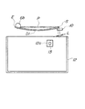
図2はシートカッタ6近傍を説明する斜視図であり、1コマ目の先端部の「縁なし」を形成している状態を示している。長尺形状のシートPには所定幅の余白部PYを設けて、複数の画像P1、P2が連続的に形成される。まず1コマ目の先端を「縁なし」とするために、シートP先端の余白部PYをシートカッタ6によって短冊状に切断する。
【0018】
切断は可動刃6bがシートPの幅方向の一端(始点側S)から他端(終点側E)に向かって移動することにより行われ、図は可動刃6bが始点側Sと終点側Eの略中間位置まで切断した状態を示している。可動刃6bにて切断される屑D1には、余白部の他に、画像が形成された領域P1’を含んでいる。
【0019】
ここで姿勢保持部材10は切断開始点の近傍に設けられており、切断されて撓んだ屑D1の先端である始点側Sがこれに支持される。従って図に示すように、可動刃6bによって略半分切断された状態にあっても屑D1は姿勢保持部材10によって落下を規制され、図6に示した如く垂れ下がることなく、略水平状態を保持している。
【0020】
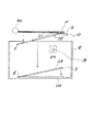
図3は可動刃6bによって屑D1が完全に切断される直前の状態を示している。可動刃6bがシートPの終点側Eに近づくにつれて、屑D1は中央部が自重により下方向に撓むこととなる。すると屑D1の始点側Sはこの撓みにより終点側Eに移動することとなる。ここで始点側Sと姿勢保持部材10の端部とのオーバーラップ量LがL>0である間は、屑D1の始点側Sは姿勢保持部材10によって落下を規制される。しかし、L<0となると姿勢保持部材10は始点側Sの落下を規制できなくなり、屑D1は図7に示した如く切り残したわずかの部分が屑D1を吊り下げた状態となってしまう。そこで姿勢保持部材10は、可動刃6bが終点側Eを切断するときまでL>0が維持される位置、大きさに設置することが必要となる。
【0021】
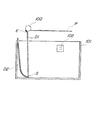
図4に示すように、終点側Eまで完全に切断された屑D1は、始点側Sが姿勢保持部材10によって規制されているため、まず終点側Eから落下する。しかし落下中に始点側Sは姿勢保持部材10の端部まで滑るため、オーバーラップ量Lが0となった瞬間に姿勢保持部材10は屑D2の始点側Sの落下を規制できなくなる。このため落下中の屑D3は屑D2と同じ姿勢のまま落下し、屑収納ボックス12の底に屑D3の終点側Eが衝突するとその終点側Eを始点として回転し、屑D4は屑収納ボックス12の底に載置される。
【0022】
このように構成したことにより、切断された屑が散逸することなく、常に安定して同様の位置に堆積させることができる。従って屑収納ボックス12内の屑の量を屑量検知センサ13によって確実に検知することができ、屑が屑収納ボックス12からあふれたり、まだ収納できるのに満杯であると誤検知することを確実に回避することができる。
【0023】
また1コマ目の画像P1を「縁なし」とするために、隣接する画像P1、P2の間の余白部PYを短冊状に切断する。この短冊状の屑には画像P1およびP2の一部を含むことにより、切り離された画像を「縁なし」とすることができる。なお切り離された屑は上記説明と全く同様に、屑収納ボックス12の底に安定して落下、堆積される。
【0024】
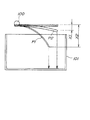
また図5に示すように、幅の狭いシートQを使用する場合には、始点側Sが姿勢保持部材10に規制される位置に搬送する。そして切断された屑F1は、上記D1〜D4と全く同様に、終点側Eが降下し(F2)、そのままの姿勢で姿勢保持部材10の底まで落下し(F3)、終点側Eを中心に回動して姿勢保持部材10の底に載置される(F4)。
【0025】
従って屑収納ボックス12の穴12a及び屑量検知センサ13は、始点側Sと終点側Eの中央よりも始点側Sよりに設けられている。これにより幅の異なるシートを搬送する場合にも安定して屑D、Fの堆積を検知することができ、屑が屑収納ボックス12からあふれることを確実に回避することができる。
【0026】
なお、上記各実施形態においては固定刃6aと回動する可動刃6bとを組み合わせたロータリカッタを用いて説明したが、本発明はこれに限定するものではなく、固定刃と回動する長尺刃とを組み合わせた押し切りカッタ等、一端から他端までを同時に切断しないカッタであれば、本発明を適用することができる。
【0027】
また、上記実施形態においては屑の量を検知するセンサとして発光素子と受光素子とからなる透過方式のフォトインタラプタを用いて説明したが、屑の表面の反射光を利用した反射方式のセンサを用いて検知を行うことでもよい。
【0028】
【発明の効果】
上記説明した如く、本発明に係るシートカッタ及び画像形成装置は、カッタと屑収納ボックスとの間に屑の落下を規制する姿勢保持部材を設けたことにより、切断された屑が散逸したり、屑収納ボックスの壁によりかかったりすることなく、常に安定して同様の位置に整然と堆積させることができる。従って屑収納ボックス内の屑の量をセンサによって確実に検知することができ、屑が屑収納ボックスからあふれたり、まだ収納できるのに満杯であると誤検知することを確実に回避することができる。
【0029】
また屑の落下位置が安定することから、屑収納量を減らすことなく屑収納ボックスの大きさを小さくすることができ、装置全体の小型化を図ることができるとともに、生産コストの低減を図ることができる。
【図面の簡単な説明】
【図1】本発明に係る画像形成装置の概略構成図である。
【図2】シートカッタ近傍を説明する斜視図である。
【図3】切断される直前の状態を説明する図である。
【図4】切断された後の状態を説明する図である。
【図5】幅の狭いシートを切断する状態を説明する図である。
【図6】従来のシートカッタ近傍を説明する斜視図である。
【図7】従来の切断される直前の状態を説明する図である。
【図8】従来の切断された後の状態を説明する図である。
【符号の説明】
D …屑
E …終点側
P …シート
S …始点側
1 …画像形成装置
2 …給送部
2a …給送ローラ
3 …搬送ローラ対
4 …記録部
5 …搬送ローラ対
6 …シートカッタ
6a …固定刃
6b …可動刃
7 …排出ローラ対
8 …排出トレイ
10 …姿勢保持部材
11 …屑ガイド
12 …屑収納ボックス
12a …穴
13 …屑量検知センサ
14 …マイクロスイッチ[0001]
BACKGROUND OF THE INVENTION
The present invention relates to a sheet cutter provided in a photographic printing apparatus or an ink jet printer that outputs a borderless print.
[0002]
[Prior art]
Traditionally, silver halide photograph prints have transitioned from “with borders” with margins around them to “no borders” with no margins. Also, digital photo printers other than silver halide photos that have no borders have been commercialized.
[0003]
In such printing apparatuses and printers, both ends (left and right ends) in the direction perpendicular to the sheet conveyance direction are exposed or printed more than the sheet width, resulting in “no borders”. For both ends (front and rear ends), “no border” is usually realized by cutting an excess portion with a cutter after exposure or printing. This is because, in order to convey the sheet, it is easy to provide a conveyance mechanism such as a conveyance roller outside the exposure or printing area, and therefore, a long roll paper is generally used for the sheet.
[0004]
In this case, if exposure or printing is performed without providing a margin between the next frame, very high cutting position accuracy is required when cutting with a cutter. Therefore, it is often the case that a blank is provided between the frames and the blank is cut into a strip shape. As a result, even if the cutting position accuracy of the cutter is somewhat poor, it is possible to avoid the adjacent frame image from entering.
[0005]
However, a mechanism for collecting the generated strip-shaped waste is necessary, and for example, as shown in JP-A-11-O07087, it is necessary to install a waste storage box below the cutter. In addition, it is necessary to arrange a sensor for detecting that the waste box is full of waste as disclosed in JP-A-08-323231.
[0006]
Thus, when detecting the quantity of refuse with a sensor, it is necessary to make the position which a sensor detects into the position where waste accumulates most in a waste storage box. Alternatively, it is conceivable to separately provide a mechanism for leveling the accumulated debris as described in JP-A-09-047681. However, if such a mechanism is provided, the apparatus may be complicated and the production cost may increase. is there.
[0007]
[Problems to be solved by the invention]
By the way, when the sheet P is cut into a strip shape by the
[0008]
This state is an unstable state in which the waste D1 can hardly be supported anymore, and as a result, the waste D1 tends to stand substantially vertically. Also, at the moment of complete cutting, the cutting force of the
[0009]
Further, when there are a plurality of types of sheet widths and thicknesses, the sagging amount X varies from sheet to sheet. For example, when considering a sheet having the same material and only a different thickness, when comparing a thin sheet P1 having a thickness of 1 and a thick sheet P2 having a thickness of 2, the amount of bending of the sheet is inversely proportional to the cube of the thickness. The dead weight is proportional to the first power of the thickness. Therefore, when considered comprehensively, the relationship between the deflection amount X1 of the sheet P1 and the deflection amount X2 of the sheet P2 is X1 = X2 * 4, and the thin sheet hangs down four times more. If the end point side E is cut in this state, the falling position on the start point side S is greatly different as shown in FIG. That is, there is a problem that the position where the crests are formed differs depending on the type of the sheet, and the position where the
[0010]
Accordingly, the present invention provides a sheet cutter and an image forming device that stabilizes the posture of different scraps to be cut with a very simple configuration, and detects the position at which the most scrap is accumulated, thereby preventing the scraps from overflowing from the scrap storage box. The object is to provide a device.
[0011]
[Means for Solving the Problems]
In order to solve the above-described problems, a typical configuration of a sheet cutter and an image forming apparatus according to the present invention includes a cutter that cuts a sheet into a strip shape from one end to the other end in the width direction of the sheet, and the cutter. A sheet cutter having a waste storage box for recovering scraps cut into strips, between the cutter and the waste storage box , provided on the cutting start point side of the cutter , and falling of waste It has the attitude | position holding member which regulates.
[0012]
DETAILED DESCRIPTION OF THE INVENTION
Embodiments of a sheet cutter and an image forming apparatus according to the present invention will be described with reference to the drawings. 1 is a schematic configuration diagram of an image forming apparatus according to the present embodiment, FIG. 2 is a perspective view illustrating the vicinity of a sheet cutter, FIG. 3 is a diagram illustrating a state immediately before cutting, and FIG. 4 is a diagram after cutting. FIG. 5 is a diagram for explaining a state, and FIG. 5 is a diagram for explaining a state of cutting a narrow sheet.
[0013]
In the
[0014]
The recording unit 4 records image information on the sheet P according to a command from a computer or the like (not shown). The sheet P on which an image is recorded by the recording unit 4 is conveyed downstream by the conveying roller pair 5. A
[0015]
The
[0016]
The
[0017]
FIG. 2 is a perspective view for explaining the vicinity of the
[0018]
The cutting is performed by moving the
[0019]
Here, the
[0020]
FIG. 3 shows a state immediately before the scrap D1 is completely cut by the
[0021]
As shown in FIG. 4, the scrap D <b> 1 completely cut to the end point side E first falls from the end point side E because the start point side S is regulated by the
[0022]
By comprising in this way, the cut | disconnected waste can be always deposited stably in the same position, without dissipating. Therefore, the amount of waste in the
[0023]
Further, in order to make the image P1 of the first frame “no border”, the blank portion PY between the adjacent images P1 and P2 is cut into a strip shape. By including a part of the images P <b> 1 and P <b> 2 in the strip-shaped waste, the separated image can be “edgeless”. The separated waste is stably dropped and deposited on the bottom of the
[0024]
Also, as shown in FIG. 5, when using a narrow sheet Q, the starting point side S is conveyed to a position regulated by the
[0025]
Therefore, the
[0026]
In each of the embodiments described above, the rotary cutter in which the fixed blade 6a and the rotating
[0027]
Moreover, in the said embodiment, although demonstrated using the transmissive photo interrupter which consists of a light emitting element and a light receiving element as a sensor which detects the quantity of refuse, the reflection type sensor using the reflected light of the surface of waste is used. Detection may be performed.
[0028]
【The invention's effect】
As described above, the sheet cutter and the image forming apparatus according to the present invention provide a posture holding member that restricts the falling of the waste between the cutter and the waste storage box, so that the cut waste is dissipated, Without being caught by the wall of the waste storage box, it can always be stably and orderly deposited at the same position. Therefore, the amount of waste in the waste storage box can be reliably detected by the sensor, and it is possible to reliably avoid erroneous detection that the waste overflows from the waste storage box or is full even though it can still be stored. .
[0029]
Moreover, since the falling position of the trash is stable, the size of the trash storage box can be reduced without reducing the amount of trash stored, the overall apparatus can be downsized, and the production cost can be reduced. Can do.
[Brief description of the drawings]
FIG. 1 is a schematic configuration diagram of an image forming apparatus according to the present invention.
FIG. 2 is a perspective view for explaining the vicinity of a sheet cutter.
FIG. 3 is a diagram illustrating a state immediately before cutting.
FIG. 4 is a diagram illustrating a state after cutting.
FIG. 5 is a diagram illustrating a state in which a narrow sheet is cut.
FIG. 6 is a perspective view illustrating the vicinity of a conventional sheet cutter.
FIG. 7 is a diagram for explaining a state just before the conventional cutting.
FIG. 8 is a diagram for explaining a state after a conventional cutting.
[Explanation of symbols]
D ... Waste E ... End point side P ... Sheet S ... Start point side 1 ...
10 ... Posture holding member
11… Trash guide
12… Trash storage box
12a ... hole
13 ... Waste amount detection sensor
14… Micro switch
Claims (4)
前記カッタで短冊状に切断された屑を回収する屑収納ボックスとを有するシートカッタであって、
前記カッタと前記屑収納ボックスとの間であって、前記カッタの切断開始点側に設けられ、屑の落下を規制する姿勢保持部材を有することを特徴とするシートカッタ。A cutter for cutting the sheet into a strip shape from one end to the other end in the width direction of the sheet;
A sheet cutter having a waste storage box for collecting waste cut into strips by the cutter,
A sheet cutter comprising a posture holding member that is provided between the cutter and the waste storage box and is provided on a cutting start point side of the cutter and restricts dropping of the waste.
前記シートを搬送するシート搬送手段と、
請求項1乃至3のいずれか1項記載のシートカッタとを有することを特徴とする画像形成装置。Image forming means for recording an image on a sheet;
Sheet conveying means for conveying the sheet;
An image forming apparatus comprising: the sheet cutter according to claim 1.
Priority Applications (1)
| Application Number | Priority Date | Filing Date | Title |
|---|---|---|---|
| JP2000313035A JP4442844B2 (en) | 2000-10-13 | 2000-10-13 | Sheet cutter and image forming apparatus |
Applications Claiming Priority (1)
| Application Number | Priority Date | Filing Date | Title |
|---|---|---|---|
| JP2000313035A JP4442844B2 (en) | 2000-10-13 | 2000-10-13 | Sheet cutter and image forming apparatus |
Publications (3)
| Publication Number | Publication Date |
|---|---|
| JP2002120967A JP2002120967A (en) | 2002-04-23 |
| JP2002120967A5 JP2002120967A5 (en) | 2007-11-22 |
| JP4442844B2 true JP4442844B2 (en) | 2010-03-31 |
Family
ID=18792518
Family Applications (1)
| Application Number | Title | Priority Date | Filing Date |
|---|---|---|---|
| JP2000313035A Expired - Fee Related JP4442844B2 (en) | 2000-10-13 | 2000-10-13 | Sheet cutter and image forming apparatus |
Country Status (1)
| Country | Link |
|---|---|
| JP (1) | JP4442844B2 (en) |
Families Citing this family (9)
| Publication number | Priority date | Publication date | Assignee | Title |
|---|---|---|---|---|
| JP4770545B2 (en) * | 2006-03-28 | 2011-09-14 | Nkワークス株式会社 | Printing device |
| JP2008296496A (en) * | 2007-06-01 | 2008-12-11 | Mitsubishi Electric Corp | Printer device |
| JP4894737B2 (en) * | 2007-11-28 | 2012-03-14 | 富士ゼロックス株式会社 | Paper processing device |
| JP6283179B2 (en) * | 2013-07-22 | 2018-02-21 | キヤノンファインテックニスカ株式会社 | Sheet cutting device |
| US10173337B2 (en) | 2013-07-22 | 2019-01-08 | Canon Finetech Nisca Inc. | Sheet cutting device |
| JP6326571B2 (en) * | 2013-07-31 | 2018-05-23 | デュプロ精工株式会社 | Processing apparatus and cutting method |
| JP6146218B2 (en) * | 2013-09-10 | 2017-06-14 | セイコーエプソン株式会社 | Cutting apparatus and recording apparatus |
| JP6115778B2 (en) * | 2013-09-13 | 2017-04-19 | フリュー株式会社 | Photo sticker creation apparatus, printing method therefor, and program |
| JP7215165B2 (en) * | 2018-12-28 | 2023-01-31 | セイコーエプソン株式会社 | Hopper and cutting equipment |
-
2000
- 2000-10-13 JP JP2000313035A patent/JP4442844B2/en not_active Expired - Fee Related
Also Published As
| Publication number | Publication date |
|---|---|
| JP2002120967A (en) | 2002-04-23 |
Similar Documents
| Publication | Publication Date | Title |
|---|---|---|
| EP2218668B1 (en) | Feeding device and image recording apparatus with the feeding device | |
| JP2007223735A (en) | Image recording device | |
| US20070182083A1 (en) | Image forming apparatus and sheet feeding cassette | |
| JP4442844B2 (en) | Sheet cutter and image forming apparatus | |
| US20110310207A1 (en) | Image recording device | |
| JP2007230677A (en) | Image recorder | |
| JP2006321593A (en) | Image forming device | |
| JP4235414B2 (en) | Sheet cutting apparatus and recording apparatus | |
| EP1610541A1 (en) | Reliable detection of originals in an image processing apparatus with a single mechanism for separating and supplying both originals and recording materials | |
| JP4552558B2 (en) | Roll paper cutting device, roll paper cutting method, and image forming apparatus | |
| JP3088761B2 (en) | Color image forming equipment | |
| US20020146270A1 (en) | Roller system to help remove chad and trimmed media in a thermal printer | |
| JP4302670B2 (en) | Image forming apparatus | |
| JP2007110658A (en) | Paper sheet feeding apparatus and image reading position adjusting method | |
| JPH09107433A (en) | Facsimile equipment | |
| JP3321322B2 (en) | Image forming device | |
| JP3611539B2 (en) | Image forming apparatus | |
| JP2004177836A (en) | Image forming apparatus | |
| JP4808466B2 (en) | Recording medium storage device | |
| JP3817795B2 (en) | Image forming apparatus | |
| JP2006327721A (en) | Printer | |
| JP2007118360A (en) | Printer | |
| JP2006117391A (en) | Method for driving medium feeding device, drive control program, and recording device | |
| JP4327032B2 (en) | Paper feed tray, paper feed device, and image forming apparatus | |
| JP3912899B2 (en) | Stacker device |
Legal Events
| Date | Code | Title | Description |
|---|---|---|---|
| A521 | Written amendment |
Free format text: JAPANESE INTERMEDIATE CODE: A523 Effective date: 20071005 |
|
| A621 | Written request for application examination |
Free format text: JAPANESE INTERMEDIATE CODE: A621 Effective date: 20071005 |
|
| RD02 | Notification of acceptance of power of attorney |
Free format text: JAPANESE INTERMEDIATE CODE: A7422 Effective date: 20080116 |
|
| A977 | Report on retrieval |
Free format text: JAPANESE INTERMEDIATE CODE: A971007 Effective date: 20091007 |
|
| A131 | Notification of reasons for refusal |
Free format text: JAPANESE INTERMEDIATE CODE: A131 Effective date: 20091013 |
|
| A521 | Written amendment |
Free format text: JAPANESE INTERMEDIATE CODE: A523 Effective date: 20091208 |
|
| TRDD | Decision of grant or rejection written | ||
| A01 | Written decision to grant a patent or to grant a registration (utility model) |
Free format text: JAPANESE INTERMEDIATE CODE: A01 Effective date: 20100106 |
|
| A01 | Written decision to grant a patent or to grant a registration (utility model) |
Free format text: JAPANESE INTERMEDIATE CODE: A01 |
|
| A61 | First payment of annual fees (during grant procedure) |
Free format text: JAPANESE INTERMEDIATE CODE: A61 Effective date: 20100108 |
|
| R150 | Certificate of patent or registration of utility model |
Free format text: JAPANESE INTERMEDIATE CODE: R150 |
|
| FPAY | Renewal fee payment (event date is renewal date of database) |
Free format text: PAYMENT UNTIL: 20130122 Year of fee payment: 3 |
|
| FPAY | Renewal fee payment (event date is renewal date of database) |
Free format text: PAYMENT UNTIL: 20140122 Year of fee payment: 4 |
|
| LAPS | Cancellation because of no payment of annual fees |